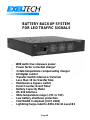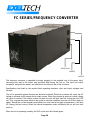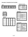
1
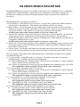
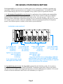
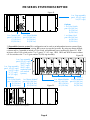
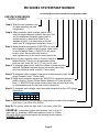
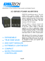
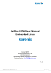
Manufacturer of UL Listed Products
R
Manufacturer of True Sine Wave Power Inverters and Related Products
MX SERIES POWER INVERTERS
EXELTECH manufactures the world's first truly
redundant, modular inverter system; the most
reliable inverter system available.
No single
malfunction will cause the inverter system to fail.
Modules are "hot" insertable. Power levels are
expandable, and modules can be added or
replaced without interruption in power to your
.
critical loads.
MX SERIES FAMILY
N+1 REDUNDANT
EXPANDABLE
REMOTE SWITCHING
TRUE SINE WAVE
“HOT” INSERTABLE
1000 WATT MODULES
REMOTE METERING
ADJUSTABLE POWER
The MX system can be configured for power
levels from 1 to 20KW with 120 Vac output. Up
to 40KW at 240 Vac bi-phase or 60KW at 208
Vac 3 phase with many input and output voltages
.
also available.
A control card and any number of
additional
1000 Watt power modules combine to make a
standard inverter. This type of system can be
expanded as power requirements increase, and
.
upgraded to be N+1 redundant as desired.
The MX system is extremely compact and
lightweight. Power modules weigh only 7 lbs.
.
Each.
Output voltage is precisely regulated, so that no
measurable voltage change occurs on the output
as input voltage fluctuates. Similarly, less than
0.5 volt change in output voltage will occur when
the output load varies from 0 to 100% of rated
power.
With distortion of 2% maximum, this
inverter offers the cleanest sine wave power
.
available.
Models are available which cover all standard
battery systems. Custom models can be designed
to meet your specific input voltage requirements.
Page 1
MX SERIES MODULE DESCRIPTION
The Exeltech MX Series of inverters is a modular system which can be assembled in many combinations
to afford the user infinite flexibility. Options such as AC distribution, AC disconnect, metering, DC
disconnect, DC distribution, transfer switch and maintenance bypass switch are also available; (see
accessories).
The building blocks of the system are as follows:
1.) Power Module - A 1000 Watt slave power inverter. It requires drive signals from a Master Module or
Control Card as described below. This module is the backbone of the inverter system.
2.) Master Module - A 1000 Watt power inverter which contains all the electronics necessary to operate.
Requires an enclosure to provide connections to the battery and AC output. It can also operate up to 19
slave Power Modules. If this module is used, the system cannot be fully redundant.
All MX systems require either a master module or at least one control card.
3.) Control Card - Generates all the signals necessary to operate up to 20 Power Modules. The card itself
will not generate any AC output power nor does any power flow through it. This card can be
paralleled with another Control Card to generate a redundant set of control signals to form the basis of
a completely redundant inverter system.
All MX systems require either a master module or at least one control card.
4.) Alarm Card - Can be used in conjunction with a redundant or non redundant inverter to provide various
alarm output signals via LED's and alarm contact closures. Must be included in redundant systems to
detect failure of control card.
5.) Transfer Switch - Provides the same functions as the alarm card, plus provides a relay to transfer AC
power to the load, from either the inverter or the utility input. Use only with systems 7KW of or less.
The above modules can be placed in the following enclosures; Installations can either be free standing
or in standard relay racks.
1.) 19" cage assembly - Compatible with a 19" relay rack. The smallest cage which can contain a
redundant system. Available in the following configurations:
19A - Basic configuration for a redundant system. Holds up to 4 Power Modules, 2 Control Cards and
either a Transfer Switch or an Alarm Card.
19B - Used as an expansion rack or may be used as an expandable, non redundant inverter, up to 5 KW.
This configuration will not accept X-fer Switch, alarm card or control cards.
2.) 23" cage assembly - Compatible with a 23" relay rack.
23A - Basic configuration for a redundant system. Holds up to 5 Power Modules, 2 Control Cards and
either a Transfer Switch or an Alarm Card.
23B - Used as an expansion rack or may be used as an expandable, non redundant inverter, up to 6 KW.
This configuration will not accept X-fer Switch, alarm card or control cards.
3.) 7" cage assembly - for 1 or 2KW systems when redundancy is not required.
7C - Consists of 1 Transfer Switch and 1 Master Module.
This configuration will not accept an alarm card or control cards.
7B - Expandable up to 2KW. 1 Master Module and 1 Power Module.
This configuration will not accept X-fer switch, alarm card or control cards.
4). 9" cage assembly- for 1-3KW systems when redundancy is not required.
9C - Consists of Transfer Switch, 1 Master Module and 1 Power Module.
This configuration will not accept an alarm card or control cards.
9B - Expandable up to 3KW. 1 Master Module and 2 Power Modules.
This configuration will not accept X-fer Switch, alarm card or
control cards.
Page 2
MX SERIES SYSTEM DESCRIPTION
The Exeltech MX Series of inverters is available in three basic architectures; redundant, upgradable and
expandable. Different options and sizes are available to fit varying applications. As a benefit of the MX
series modular design, power levels are expandable in any system, as power requirements increase.
1.) N+1 Redundant-Expandable Inverter System: For applications where reliability and maintainability
are paramount, the N+1 redundant system offers the most cost effective method of achieving redundancy
and the ability to maintain the system while loads remain on line. All cards (except 12 Vdc) are "hot"
insertable to allow maintenance without interrupting power to critical loads. Designing the power level with
N+1 number of power modules, allows for redundancy without necessitating the purchase of a duplicate
system. (An A/B Buss option is available, which adds to system reliability).
A redundant system consists of:
MX ALARM CARD
MX
MX
CONTROLCONTROLMX 1000 Power Module
CARD
CARD
Overload
MX 1000 Power Module
Overload
MX 1000 Power Module
Overload
MX 1000 Power Module
Overload
MX 1000 Power Module
Overload
Load
Load
Load
Load
Load
On
On
On
On
On
DC
On
AC POWER
INV
On
Load
INV
Fail
BRKR
Open
High
Temp
CB1
1 ea. Alarm Card
part # H (100 Vac)
A (120 Vac)
F (230 Vac)
Low
Volt
On
INV
Off
2 ea. Control Cards
part # LL (100 Vac)
CC (120 Vac)
EE (230 Vac)
Options: 1 ea. X-fer switch
part # G (100 Vac)
X (120 Vac)
Z (230 Vac)
X-fer switch includes alarms
and replaces the alarm card.
At least 3 Power Modules
part # P (100 Vac)
P (120 Vac)
R (230 Vac)
1 ea. Cage assembly
part # 1A (19" cage)
2A (23" cage)
expansion rack
part # 1B (19" cage)
2B (23" cage)
...integrates with rack A for accommodating additional
power modules, up to total rating of 20KW. Additional
control cards and a larger X-fer switch may be required.
Please call the factory for assistance.
2.) Upgradable Inverter System: The Upgradable system offers the flexibility to add a X-fer switch or
alarm card and Full Redundancy for future requirements. A minimum system with as little as one control
card and one power module can be upgraded in the future to include additional power modules, X-fer switch
or alarm card and an additional control card for full redundancy (see figure II).
Page 3
MX SERIES SYSTEM DESCRIPTION
Figure II.
1 ea. Cage assembly
part # 1A (19" cage)
2A (23" cage)
MX
CONTROLMX 1000 Power Module
Overload
CARD
Load
On
Options:
1 ea. X-fer Switch
part # G (100 Vac)
X (120 Vac)
Z (230 Vac)
1 ea. Control Card
part # L*(100 Vac)
C*(120 Vac)
E*(230 Vac)
1 ea. Alarm Card
part # H (100 Vac)
A (120 Vac)
F (230 Vac)
1 ea. Power Module
part # P (100 Vac)
P (120 Vac)
R (230 Vac)
3.)Expandable inverter system:This configuration can be used as an independent inverter system (figure
III), or to expand power levels of existing MX systems (see stacked systems). By using one master module,
a system may be expanded to include a X-fer switch and additional power modules(see figure IV). 1KW
inverters with a X-fer switch use the 7"or 9" (part # 7C, 9C) cage. 1KW, 2KW and 3KW inverters without
a X-fer switch use the 7" or 9" (part number 7B, 9B) cage assembly.
Figure III.
1 ea. Cage assembly
part # 1B (19" cage)
2B (23" cage)
7B (7" cage)
1 ea. Cage assembly 9B (9" cage)
part # 1A (19" cage) expansion rack
2A (23" cage) (see stacked
7C (7" cage)
systems)
9C (9" cage)
Options:
1 ea. X-fer Switch
part # G (100 Vac)
X (120 Vac)
Z (230 Vac)
MX TRANSFER SWITCH
MX 1000 Power Module
Overload
MX 1000 Power Module
Overload
MX 1000 Power Module
Overload
MX 1000 Power Module
Overload
MX 1000 Power Module
Overload
MX 1000 Power Module
Overload
Load
Load
Load
Load
Load
Load
On
On
On
On
On
On
Up to 5
Power Modules
1 ea. Master Module
part # Q* (100 Vac) part # P (100 Vac)
P (120 Vac)
M* (120 Vac)
Figure IV.
R (230 Vac)
O* (230 Vac)
1 ea. Master Module1
part # Q* (100 Vac)
M* (120 Vac)
N* (230 Vac)
ON
MX 1000 Power Module
Overload
OFF
Load
INVERTER
DC
VOLTAGE
MAIN AC
BREAKER
ON
On
MODULE
FAIL
TEMP
LOAD
UTIL
UTIL
SOURCE
INV
OURCE
ERTER
OFF
IMARY
VERSE
UTIL
I
SELECT
INV
1 Alarm
card is not an option on this configuration
Page 4
MX SERIES SYSTEM PART NUMBER
Use the Design Chart to formulate the 15 digit model number.
EXELTECH MX SERIES
MODEL NUMBER
__ __
__ __ __
__
__ __ __
__
__
Step 1: Enter the two character code
for cage assembly size and
configuration.
Step 2: When a transfer switch or alarm card is used,
enter the single character code for that card. 2nd
and 3rd characters designate option level of
transfer switch or alarm card. Enter 00 for
standard module, if no alarm card or transfer
switch use “B” configuration backplane, enter (***).
Step 3: Alpha character assigned by EXELTECH to represent changes or revision levels in racks, alarm cards,
or transfer switch. Enter(-). EXELTECH will assign
revision level. See revision level chart on
www.exeltech.com for the most current revision list.
Step 4: Enter the two character code for Control Card(s) or
Master Module. There is not an application where
both are used. Enter (M*) or (C*) if only one is used.
Step 5: To designate power level, enter the number of power modules
required. Redundant systems require continuous load rating
plus one additional power module(* if none used).
Step 6: To designate output voltage of the power module required, enter the
single character code(* if none used).
Step 7: Single alpha character assigned by EXELTECH represents changes or
revision levels in Control Cards, Master Modules, or Power Modules.
Enter (-). EXELTECH will assign revision level. See revision level chart
on www.exeltech.com for the most current revision list.
Step 8: To designate input voltage, enter the single character from the VDC voltage
chart below.
Vdc INPUT VOLTAGE CHART
DC Volts
12
Designation 1
24
2
32
B
48
4
66 108
I
E
Step 9: Output frequency is designated by using the first number of the frequency
(5for 50Hz, 6 for 60Hz, 4 for 400Hz).
Step 10: For options, enter two digit code. If no option, enter (00).
EXAMPLE: A redundant system with an alarm card, to fit a 23"
wide cage, for powering a 4000 watt continuous load, at 120Vac,
60Hz with 48Vdc input would require the following model number...
2AA00ACC5P-4600
Page 5
__
__
__ __
MX SERIES MODULE PART NUMBER
EXELTECH MX SERIES
MODULE NUMBER
MX
__
-
__
-
__
-
__
-
__
-
__ __
Step 1: Model number always starts
with MX.
Step 2: To designate a cage assembly, enter the
two character code from the design chart.
When ordering a power module
or master module, enter a “K”. If ordering
any other module, enter an asterisk(*).
Step 3: To designate the type of module, enter the single
character code from the design chart. To
designate cage assembly, enter an asterisk(*).
Step 4: To designate input voltage, enter the single
character code from the Vdc INPUT VOLTAGE
CHART below. If ordering an alarm card, transfer
switch or cage assembly, enter an asterisk(*).
Vdc INPUT VOLTAGE CHART
DC Volts
12
Designation 1
24
2
32
B
48
4
66 108
I
E
Step 5: Output frequency is designated by using the first number of
the frequency(5 for 50Hz, 6 for 60Hz, 4 for 400Hz). If ordering
a transfer switch, alarm card, power module or cage assembly,
enter an asterisk(*).
Step 6: This space designates current revision level, and is for
EXELTECH use only. If no revision is in use for this
module, no number or character will be used.
Step 7: To designate option, enter the code from the option chart below. If no option is required
please leave blank.
MODULE EXAMPLES: A 12Vdc, 120Vac, 60Hz master
module would require the following module number...
OPTION CHART
MXK-M-1-6-1
Option
Conformal coating
Low idle current
Code
07
08
A 48vdc, 120Vac, 60Hz power module with conformal
coating option would require the following module number...
MXK-P-4-*-1-07
CAGE ASSEMBLY EXAMPLE: A 19" redundant cage,
120Vac would require the following module number:
MX1A-*-*-*-2
Page 6
MX SERIES SYSTEMS DESIGN CHART
MX SYSTEMS DESIGN CHART
Use X-fer or Alarm Card
X-FER
SWITCH
CAGE
ASSY
SYSTEMS
SIZE
100Vac
REQUIRED
AND
120Vac
CONFIG.
230Vac
Use CC or MM
ALARM CONTROL MASTER POWER
CARD
CARD
MODULE MODULE
G
X
H
A
Z
F
Redundant
Upgradable
19" Cage
1A
0 or 1
Redundant
Upgradable
23" Cage
2A
0 or 1
0 or 1
Expandable
19" Cage
1A
0 or 1
Expandable
23" Cage
2A
Expandable
7" Cage
1, 4
L* or LL
C* or CC
Q*
M*
P
P
E* or EE
O*
R
1, 4
5
C- Current
F- Future
3
C
0
up to 4
0, 1, 2
0
up to 5
0
0
1
up to 3
C
0 or 1
0
0
1
up to 4
C
7B
0
0
0
1
0 or 1
C
Expandable
9" Cage
9B
0
0
0
1
up to 2
C
Expandable
19" Cage
1B
0
0
0
1
up to 4
C
Expandable
23" Cage
2B
0
0
0
1
up to 5
C
Expandable
7" Cage
7C
0 or 1
0
0
1
0
C
Expandable
9" Cage
9C
0 or 1
0
0
1
0 or 1
F
Split Phase
19" Cage
1E
0
0
0
2
0 or 2
F
Split Phase
23" Cage
2E
0
0
0
2
0,2,4
F
Split Phase
7" Cage
7E
0
0
0
2
0
C
3 Phase
19" Cage
1F
0
0 or 1
0
3
0
F
3 Phase
23" Cage
2F
0
0 or 1
0
3
0 or 3
C
3 Phase
9" Cage
9F
0
0
0
3
0
C
1, 4
0 or 1
0, 1, 2
AVAIL
1, 4
5
3
2
2
1
1 per phase
with a subset of functions (multi-phase option A13)
3 System is not fully redundant with less than 3 power modules
4 Minimum 1 Alarm Card or 1 X-fer Switch required for redundant system
5 Minimum 2 Control Cards for redundant system.
2 Alarm
NOTE: Any modification to any Stack System must be performed in the factory.
Page 7
C
MX SERIES POWER INVERTER SPECIFICATIONS
PROTECTION
CIRCUITRY
OUTPUT POWER
CONTINUOUS
POWER
SURGE
POWER
(3 seconds)
NO LOAD
POWER
OUTPUT
VOLTAGE
OUTPUT
CURRENT
WEIGHT
LBS.
1000W
2200W
20W
230+/-6%
4.3
7.5
1000W
2200W
20W
117+/-6%
8.6
7.5
1000W
2200W
20W
100+/-6%
10.0
7.5
MODEL
VOLTAGE
MINIMUM
(TYPICAL)
SYSTEM
(TYPICAL)
MAXIMUM
(TYPICAL)
12V
10.4/10.6*
13.8V
17V
85%
87%
24V
19/21V*
27.6V
34V
87%
89%
32V
26.5/28V*
36.8V
45V
87%
89%
48V
41.5/42.5V*
55.2V
62V
87%
89%
66V
57.5/58.5V*
75.9V
94V
88%
90%
108V
94/95V*
124V
149V
88%
90%
Over Voltage:
Under Voltage:
Thermal:
Output Short:
Shutoff at maximum input
voltage, per input conditions.
Shutoff at minimum input
voltage, per input
conditions.
105 C internal
temperature. Warning
buzz 5 C before shutoff.
Unit shuts off: Circuit
breaker protected and
electronically limited.
INPUT
TYPICAL
PEAK
EFFICIENCY EFFICIENCY
@ FULL
@ 1/3
POWER
POWER
ENVIRONMENTAL
Temperature:
Humidity:
Altitude:
Audible Noise:
Cooling:
Finish:
Warranty:
-25 to 40 C full power,
derate 20% per 10 C.
Above 40 C.
5 to 95% non-condensing
-200 to 10k feet full
power, derated above 10k
Less than 45dbA
1KW-Thermostatically
controlled forced air
Polyurethane base paint
Full year parts and labor.
*indicates typical cut-off voltage/warning buzzer voltage
GENERAL
MECHANICAL
CONDITIONS
MINIMUM
TYPICAL
MAXIMUM
WAVEFORM
-
SINUSOIDAL
-
LINE REGULATION
-
.1%
.5%
LOAD REGULATION
-
.3%
.5%
DISTORTION
-
1.5%
2%
FREQUENCY*
-.1%
NOMINAL
+.1%
*50, 60, 400Hz nominal
See www.exeltech.com for more data regarding MX Series inverters.
Page 8
Four case sizes are available; all are:
7" high X 15" deep.
19 inch Wide:
(includes hardware for
rack or shelf mounting)
23 inch Wide:
(includes hardware for
rack or shelf mounting)
9.97 inch Wide: (for 1 to 3KW applications:
surface mounting only)
7 inch Wide:
(for 1 or 2KW applications;
surface mounting only)
Available in other sizes including metric. Call
factory for sizes.
MX SYSTEMS MONITOR CARD
It is now possible to monitor all of your remote power stations, anywhere, from a single
location. You can have up to the minute verification that all of your remote power
systems are 100% operational. Your remote power system can tell you that it is currently
running at 90% of its rated capacity.
An Exeltech System Monitor card is an upgrade option for any Exeltech MX Series
Redundant or Upgradeable System equipped with an Alarm Card or New MX Systems
with a Transfer Switch. This new product allows customers to monitor all important
aspects of their power system from any IP based Ethernet network.
Customers can monitor all system alarm functions including: Power Module fail, Control
Card Fail, Over Temperature, Under DC Voltage, A-B Bus failure, System Breaker Open,
and System Failure. Additionally, customers can monitor battery voltage and current
usage, and System output voltage and current. All alarm functions are viewable from an
LCD display located on the System Monitor Card, and Ethernet connection, or a local
Rs232 connection.
Main Menu Items
The main menu consists of 9 different screens. To switch between each menu item
press the MENU button. Alarm Details and System Settings have several addition
screens available for viewing or changing system parameters, press the SELECT button
to choose a parameter for viewing or modification of settings. Hold the MENU button
down to return to the main menu screens.
Operation
Normal operation of the Monitor Card is exactly the same as a standard Exeltech Alarm
Card with the notable exception of remote monitoring of system status. A blinking LED
for the new alarm state announces new alarm states; pressing ether button stops the
blinking, and Alarm Details will give a listing of any alarms that have activated. For a
complete description of the Exeltech Alarm Card, see the Exeltech System Installation/
Operation manual.
Remote Monitoring
Remote monitoring can be performed via DHCP enabled network, or RS 232 serial port.
Monitoring software is included to allow remote sensing of alarm states, however, it is
simple to implement custom software to meet any monitoring needs.
Page 9
System Monitor Card
Turn the Inverter
Modules on or off.
Secondary
Options
Primary
Options
Disconnect will remove
the AC Voltage output
from the system.
Select a Menu item for
additional information.
Scroll thru different menu
options allowing access to
system information.
RS-232-Serial data port
Network Activity
Press Menu to scroll:
System
MajAlm
MinorAlm
SysNorm
Alarm
PRESS SELECT
Details
Vdc
0.0 V
Idc
0.0 A
Vac
0.0 V
Iac
0.0 A
Up H:M:S
HH:MM:SS
System
Settings
PRESS SELECT
Version
Version Number
Data output to monitor
the system status over
an Ethernet based
network.
Network Link
Indicator LED of
System Status.
Press Menu to scroll:
SysPower
Maint BP
FAIL,OK
ON/OFF
Breaker
DCV Alarm
ON/OFF
ON/OFF
P Mod
A-Buss
OK/FAIL
0.0 V
OverTemp
B-Buss
OK/FAIL
0.0 V
CC Stat
SysVersion
OK/FAIL
Current Version
Press Menu to scroll:
RS232 Send
ON/OFF
Ethernet Send
ON/OFF
RS232 Baud
Several Selections
ReInit Ethernet
Software Reboot
Page 10
Manufacturer of UL Listed Products
R
Manufacturer of True Sine Wave Power Inverters and Related Products
XP SERIES POWER INVERTERS
XP 125
XP 250
Made in America, EXELTECH XP
SERIES INVERTERS are the most
affordable, reliable, lightweight and
best regulated, true sine wave inverters
available. The XP SERIES inverter will
operate any AC load anywhere. Ultra
lightweight, yet rugged enough for the
most extreme mobile enviroments, the XP
SERIES is available in 100Vac, 120Vac,
or 230Vac in 50Hz, 60Hz or 400Hz for land,
marine or military applications, worldwide.
TRUE SINE WAVE
XP 600
125 WATTS TO 2000 WATTS
12VDC TO 108VDC INPUT
RACK MOUNT OPTIONAL
XP 1100
REMOTE SWITCHING
21.5 YEARS MTBF
XP 2000
Page 11
XP SERIES PART NUMBERING SYSTEM
EXELTECH XP SERIES
MODEL NUMBER
XP
__
-
__
-
__
-
__
-
1
-
__ __
Step 1: Model number always starts
with XP.
Step 2: To designate wattage enter the single character code
1 for 125, 2 for 250, 6 for 600, K for 1100, X for 2000
Step 3: To designate output voltage enter the single character
code from the Vac chart
Vac OUTPUT VOLTAGE CHART
AC Volts
Designation
100 120 230*
1
0
3
*Not available in 125watt models
Step 4: To designate input voltage enter the single character code from the Vdc chart
Vdc INPUT VOLTAGE CHART
DC Volts
12
Designation 1
24
2
32
B
48
4
66 108
I
E
Step 5: Output frequency is designated by using the first number of the frequency
5 for 50Hz, 6 for 60Hz and 4 for 400 Hz
Step 6: This designates revision level (For EXELTECH use only).
Step 7: To designate option, enter the code from the option chart below. If no option is required please leave it blank.
OPTION CHART
Option
Conformal coating
Low idle current drain
Circuit board with heat sink only
50MS transfer relay
Code
07
02*
04**
20***
* available thru a distributor only(only on XP1100W)
**available for OEM’s only
***available on XP600 and XP1100 only
EXAMPLE: XP600 with
117Vac output, 12Vdc input,
60Hz with the conformal
coating option would require
the following model number:
XP6-1-1-6-1-07
Page 12
XP SERIES POWER INVERTER SPECIFICATIONS
MECHANICAL
OUTPUT POWER
CONTINUOUS
POWER
SURGE
POWER
NO LOAD
POWER
OUTPUT
VOLTAGE
OUTPUT
CURRENT
WEIGHT
LBS.
125W
150W
5W
100 +/-6%
1.2
2
125W
150W
5W
117 +/-6%
1.1
2
250W**
300W
6W
100 +/-6%
2.5
5
250W**
300W
6W
117 +/-6%
2.1
5
250W**
300W
7W
230 +/-6%
1.1
5
600W**
1100W
8W
100 +/-6%
6.0
6.5
600W**
1100W
8W
117 +/-6%
5.1
6.5
600W**
1100W
9W
230 +/-6%
2.7
6.5
1100W**
2200W
20W*
100 +/-6%
11.0
10
1100W**
2200W
20W*
117 +/-6%
9.5
10
1100W**
2200W
20W*
230 +/-6%
4.8
10
2000W
4000W
12W
120 +/-2%
16.7
15
*10W with X2 option , **remote switchable
Case size (HxWxD)
125W case size= 2.16" X 4.93" X 7.90"
(2 lbs)
250W case size= 2.77" X 5.23" X 12.03"
(5 lbs)
600W case size= 3.57" X 7.69" X 12.10"
(6.5 lbs)
1100W case size= 3.57" X 7.69" X 15.05"
(10 lbs)
2000W case size= 4” X 9” X 18”
(15 lbs)
OPTIONS
XP Options:
- conformal coating (07 option)
- low idle current drain (02 option)*
- circuit board with heat sink only
(04 option) many other options
available for OEM applications,
consult factory.
*1100 watt only
INPUT POWER
MODEL
VOLTAGE
MINIMUM
(TYPICAL)
SYSTEM
(TYPICAL)
MAXIMUM
(TYPICAL)
**12V
10.4/10.6*
13.8V
16.5V
85%
87%
24V
19/21V*
27.6V
33V
87%
89%
32V
26.5/28V*
36.8V
44V
88%
90%
*Under Voltage: Shut off at minimum input
voltage, per input conditions
48V
41.5/42.5V
55.2V
62V
87%
89%
*Thermal:
66V
57.5/58.5V*
75.9V
91V
88%
90%
105 C internal temperature.
Warning buzz 5 C before
shut off
108V
94/95V*
125V
149V
87%
90%
Output Short:
Unit shuts off (manual reset)
1
1
PEAK
EFFICIENCY
@ 1/3
POWER
PROTECTION
CIRCUITRY
TYPICAL
EFFICIENCY
@ FULL
POWER
*Indicates typical cut-off voltage/warning buzzer voltage
1
+/- 3%
** Output Power derated for XPX
*Over Voltage: Shut off at maximum input
voltage, per input conditions.
Automatic reset upon fault
correction.
*Automatically reset
ENVIRONMENTAL
GENERAL
Temperature:
-25 to 30 C full power
derated 20% per 10 C,
above 30 C.
5 to 95% non condensing
CONDITIONS
MINIMUM
TYPICAL
MAXIMUM
WAVEFORM
-
SINUSOIDAL
-
VOLTAGE OUTPUT
-5%
NOMINAL
+5%
LINE REGULATION
-
0.1%
0.5%
LOAD REGULATION
-
0.5%
1%
Audible Noise: Less than 45dbA
DISTORTION
-
1.5%
2%
Cooling:
FREQUENCY
-0.1%
NOMINAL
+0.1%
600W/1100W Thermostatically controlled
forced air. 125W/250W
convection cooled.
Finish:
Painted aluminum
Warranty:
Full year parts labor
See www.exeltech.com for more data regarding XP Series inverters.
Page 13
Humidity:
Altitude:
-200 to 10k feet full power,
derated above 10k
BATTERY BACKUP SYSTEM
FOR LED TRAFFIC SIGNALS
1000 watts true sinewave power
Power factor corrected charger
3 state temperature compensating charger
All digital control
Transfer Switch Internal or External
Less than 10 ms transfer time
Maintenance bypass switch
Event Counter, Event Timer
Battery Capacity Meter
RS-232 Interface
Wide temperature range (-37C to 74C)
Low battery shutdown protection
CALTRANS Compliant (JULY 2004)
Lightning/Surge rated to ANSI-C62.41 Level B2
Page 14
Exeltech BBS Features
Overall system features:
Integrated Inverter/charger system, designed for seamless operation together
1000 watts true sine wave inverter w/less than 2% distortion and peak efficiency
is greater than 89%
External alarm relays for remote monitoring
On battery - energizes when utilizing backup power
Low battery - energizes when batteries reach 40% remaining capacity
On time - energizes when two hours of backup have occurred
Low battery shutdown protection
LED display for all parameters
BBS status: Charge mode or BBS mode
Event counter
Accumulated Event time
External alarm relay state
Battery Capacity Meter
Battery voltage indicator
Internal or External transfer switch option
External maintenance bypass switch
Front panel multimeter test points for battery voltage measurements
Testing and certifications
Manufactured in accordance with ISO 9000/TL 9000 quality systems
Computerized calibration and testing of each system
CALTRANS compliant (JULY 2004)
Lighting/Surge rated to ANSI-C62.41 Level B2
FCC compliant to Part 15 Class A
Totally integrated system with a 20 year MTBF
Data collection, monitoring, parameter changes via RS-232 interface
BBS charger features:
Power factor corrected, 3 state battery charger
Temperature compensation
Over temperature protection for batteries (50C) halts all charging
Configurable battery parameters via RS-232
BBS Transfer Switch Features
Microprocessor controlled operation allows multi-cycle voltage calculation while
maintaining a failure detect time of less then 500 microseconds
Power conditioning maintains optimal utility voltage levels when slight variance
occur
Relay transfer time less than 10ms, optional relay less then 5ms
Page 15
FC SERIES/FREQUENCY CONVERTER
INPUT PLUG
ON/OFF
OUTPUT
The frequency converter is operated by simply plugging in the supplied cord to the power input,
connecting the load to the output plug provided, and turning the unit on. The input and output
.
receptacle, along with the switch, are mounted on the left rear side of the enclosure.
Specifications are listed on the product label regarding maximum input and output voltages and
.
currents.
The unit is protected against thermal and electrical overload. Electrical overloads will cause the AC
voltage to collapse as the inverter limits output current. When the overload is removed, output voltage
will return to normal. If the output is short circuited, the unit will latch itself off, turning the front LED
red. This requires the power switch to be cycled to reset the condition (turn the unit off then back on
again). Should the unit be thermally overloaded, too much load at too high a temperature, it will shut
off, leaving the fan running. When the internal temperature cools sufficiently the unit will turn itself
back on.
.
When the unit is operating normally, the LED on the front will indicate green.
Page 16
.
FREQUENCY CONVERTER SPECIFICATIONS
Protection Circuitry
INPUT
Thermal:
Continuous Power Max Line Voltage Freq Module Weight
LBS.
Factor Regulation Range (Hz)
Power
Size
500W
>0.98
0.5%
95-260Vac 47-63
Output:
5.5
A
Input:
105C Internal
Temperature
Current limiting
with short
circuit protection
Fuse protected
Mechanical
EFFICIENCY
Three cages are available, all are 7"
high by 18" deep
250 - 500W
> 82% @ 120
7 inch:
"N" configuration holds 2
power modules
19 inch: "N" configuration holds 5
power modules
23 inch: "N" configuration holds 6
power modules
> 85% @ 230
OUTPUT
Model
Typical
Voltage
Range Distortion
Load
Regulation
120Vac 60 Hz
120
+/- 2%
< 2%
1%
120Vac 50 Hz
120
+/- 2%
< 2%
1%
120Vac 400 Hz
120
+/- 2%
< 3%
3%
230Vac 60 Hz
230
+/- 2%
< 2%
1%
230Vac 50 Hz
230
+/- 2%
< 2%
1%
Page 17
Module size "A" - 7" high, 3.2" wide,
15.5 " deep
Environmental
Temperature: -25 to 40 C full power,
derated above 40C
Altitude:
-200 to 10k feet full
power, derated above
10k feet
Audible noise: > 45dbA
Cooling:
Thermostatically
controlled forced air
with variable speed fan
Finish:
Polyurethane based
paint
PV AC MODULE
What is a PV AC Module?
An Exeltech PV AC module is a self-contained, UL-1741 compliant inverter that
produces clean, sine-wave electricity for grid-tie applications without the complexity or
expense common in large-inverter-based systems.
Advantages Over Conventional Grid-Tie Systems
50% reduction in wiring requirements! This eliminates:
DC wiring
DC cable trays
DC fusing, overcurrent protection and required holders
DC connectors
DC ground-fault detection, protection, and devices
DC surge protection
DC combiner boxes
DC junction boxes and connector blocks
UL-related DC cabling issues
PV Series (“blocking”) diodes
PV module bypass diodes
Exeltech PV AC Module mounted to a PV
panel. All DC wiring is enclosed in the
compartment near the PV frame. The
inverter is mounted in the center
compartment. AC wiring is located in the
right-hand compartment. (Conduit and
fittings not shown are customer/installer
provided.)
Additional Benefits of Exeltech PV AC Modules
No batteries to purchase, maintain, or wear out!
More reliable - single point failure does not disable entire system!
Simplified system assembly - AC wiring connects directly to AC sub-panel with
appropriate breaker!
Incremental growth capability - no need to purchase many expensive modules at
one time.
Minimizes system design time and expense.
Significantly decreases system power reduction events due to single-module shading.
No large or heavy inverters to ship, handle, or mount.
Easy to install and service - PV panel and inverter are integrated into one unit.
No imbalance losses due to differences in PV output voltage or current.
Anti-islanding protection built into every module (per UL1741).
Microprocessor-controlled Maximum Power Point Tracking (MPPT) operates over entire
DC input voltage range.
Adaptable: J-box or Multi-contact connector input. Knock-outs for standard AC-side
conduit fittings.
Page 18
Electrical Specifications
Total Harmonic Distortion (THD): < 2%
Peak Efficiency: Greater than 91%
Rated Power: Up to 150W output per module
Input: “12V” PV (15-24V) or “24V” PV (30-48V)
MPPT voltage range: Full DC input voltage range
Output: 117VAC, 60 Hz (nominal)
Mechanical Specifications
Size (in/mm): 1.3 h x 12.5 w x 6.25 d (33 x 318 x 159)
Weight: Less than 2.5 lbs (1135 grams)
Operating Temperature: -40°C (-40°F) to +85°C (+185°F)
Certifications
Designed to meet:
UL 1741
FCC Class B
NEC 690
Manufacturers of more than 35,000 different true sine wave power inverters, chargers,
and related products.15 years of Exeltech inverter manufacturing experience and
support behind every Exeltech product. We provide the emergency backup power
systems for the Communications Center in every US Embassy, worldwide…
(Specifications subject to change without notice.).
Page 19
Manufacturer of Quality Power Products
HVGT SERIES
HIGH VOLTAGE GRID TIE INVERTER
1800 WATTS
96% EFFICIENT
COMPACT
LIGHTWEIGHT
MADE IN THE USA
The Exeltech HVGT string inverter provides the
lowest cost, highest quality, grid interactive inverter
available today. This is accomplished through snapin installation, convection cooled construction with
no moving parts, and the use of newly allowed
transformerless technology. No transformer means
less weight, less cost, and greater efficiency. By
incorporating ground fault interrupter (GFI) and
integral surge protection within the inverter, there is
no need for an external GFI or surge protection to
validate the warranty. This reduces the total installed
system cost even further. MPPT (Maximum Power
Point Tracking) is achieved with a microprocessor.
The HVGT complies with UL1741 certification, and
is in a NEMA 3R indoor/outdoor enclosure for
maximum environmental safety and protection.
Page 20
HVGT SERIES PART NUMBERING SYSTEM
EXELTECH HVGT SERIES
MODEL NUMBER
HVGT
15
__
__
__
__ __
Step 1: Model number always starts
with HVGT.
Step 2: To designate wattage
( 15 for 1500 )
Step 3: To designate voltage
Vac OUTPUT VOLTAGE CHART
AC Volts
Designation
100
J
120
230
A
E
Step 4: Output frequency is designated by using the
first number of the frequency(5 for 50Hz, 6 for 60Hz)
Step 5: This space designates current revision level, and is for
EXELTECH use only. If no revision is in use for this
module, enter 0.
Step 6: To designate option, enter the code from the option chart below. If no option is required
please leave blank.
EXAMPLES: A 120Vac, 60Hz model
OPTION CHART
would require the following model number...
Option
Code
HVGT15A60
ELECTRICAL SPECIFICATIONS
RATING TYPE
MAXIMUM SYSTEM VOLTAGE
RATING
Thermal:
450 Vdc
RANGE OF OPERATING DC VOLTAGE
200 Vdc to 450 Vdc
MAXIMUM OPERATING CURRENT (DC)
8 Amps
MAXIMUM ARRAY SHORT CIRCUIT CURRENT (DC)
10 Amps
MAXIMUM UTILITY BACKFEED CURRENT (DC)
0.1 Amps
OPERATING VOLTAGE RANGE (AC)
106 Vac - 132 Vac
OPERATING FREQUENCY RANGE
59.3Hz - 60.5Hz
NOMINAL OUTPUT VOLTAGE (AC)
120 Vac
NORMAL OUTPUT FREQUENCY
60 Hz
MAXIMUM CONTINUOUS OUTPUT CURRENT
12.0 Amps
POWER FACTOR
PROTECTION
CIRCUITRY
Output:
ENVIRONMENTAL
Temperature:
Humidity:
Altitude:
Cooling:
Finish:
1440 Watts
MAXIMUM OUTPUT FAULT CURRENT (AC)
12 Amps
MAXIMUM OUTPUT OVERCURRENT PROTECTION
15 Amps
PEAK EFFICENCY
96 %
TOTAL HARMONIC DISTORTION
5%
25 C full power,
derate above 25 C.
Indoor / Outdoor
-200 to 10k feet full
power, derated above 10k
Convection
Polyurethane base paint
MECHANICAL
> 0.99
MAXIMUM CONTINUOUS OUTPUT POWER (AC)
105 C internal
temperature.
Current limiting
Dimensions:
14” X 7” X 5” (HxWxD)
Weight:
8 lbs.
See www.exeltech.com for more data regarding HVGT Series inverters.
Page 21
XO SERIES OPERATION AND INSTALLATION MANUAL
Manufacturer of True Sine Wave Power Inverters and Related Products
XO SERIES POWER INVERTERS
EXELTECH manufactures some of the most
reliable inverter systems available. Power
levels are expandable, and modules can be
added or replaced in the field. The XO system
can be configured for power levels from
2 to 6KW with 120 VAC output, 240 VAC
.
bi-phase or 208 VAC 3 phase.
The XO system is extremely compact and
lightweight. Power modules weigh only
12 lbs each. Output voltage is precisely
regulated, so that no measurable voltage
change occurs on the output as input voltage
fluctuates. Typically, less than 1.2 volt change
in output voltage will occur when the output
load varies from 0 to 100% of rated power.
EXPANDABLE
With distortion of 2% maximum, this inverter
offers the cleanest sine wave power available.
Models are available which cover 24, 48 and
66VDC battery systems. Custom models can
be designed to meet your specific input
voltage requirements.
.
TRUE SINE WAVE
2000 WATT MODULES
EXTREMELY LIGHTWEIGHT
COMPACT
MICRO PROCESSOR
CONTROLLED
Page 22
MI SERIES OPERATION AND INSTALLATION MANUAL
XO SERIES SYSTEM PART NUMBER
EXELTECH XO SERIES
__ __ __ __ *
*
* - __ __ __ __ -
MODEL NUMBER
STEP # 1 Model number always
starts with XO
STEP # 2 Cage assembly
7
7” XO
9
9” XO
STEP # 3 Configuration
1 phase
2 phase
3 phase
B
E
F
STEP # 4 Enter three asterisks ( * )
STEP # 5 Character assigned by EXELTECH
to represent changes or revisions levels.
STEP # 6 To designate power level, enter the number
of modules required. ( * if none used)
STEP # 7 Enter from the following character code
Q = 100Vac, M = 120Vac, O = 230Vac
STEP # 8 To designate input voltage, enter the single character from the
VDC voltage chart below:
DC VOLTS
DESIGNATION
VDC INPUT VOLTAGE CHART
48
24
4
2
66
E
STEP # 9 Output frequency is designated by using the first number
of the frequency. 5 for 50Hz, 6 for 60Hz, 4 for 400Hz
STEP # 10 Character assigned by EXELTECH to represent
revision level of Power Modules.
STEP # 11 For options, enter two digit code. If no option, enter (00).
Example:
XO9B***-3ME6-01
Page 23
__ __
POWER INVERTER SPECIFICATIONS
PROTECTION
CIRCUITRY
OUTPUT POWER
CONTINUOUS
POWER
SURGE
POWER
NO LOAD
POWER
OUTPUT
VOLTAGE
OUTPUT
CURRENT
per KW
WEIGHT
LBS.
2000W
4000W
12W
1
8.3 A
15
4000W
8000W
24W
1, 2
8.3 A
28.6
6000W
12000W
35W
1, 3
8.3 A
37
Over Voltage:
Under Voltage:
Thermal:
Output Short:
Shutoff at maximum input
voltage, per input table.
Shutoff at minimum input
voltage, per input table.
105 C internal
temperature.
Unit shuts off:
electronically limited.
Manual reset required.
1 Single phase 100Vac, 120Vac +/- 2%
2 Bi-phase 100/200Vac, 120/240Vac +/- 2%
3 3 phase 100/173Vac, 120/208Vac +/- 2%
INPUT
TYPICAL
PEAK
EFFICIENCY EFFICIENCY
@ FULL
@ 1/2
POWER
POWER
MODEL
VOLTAGE
MINIMUM
(TYPICAL)
SYSTEM
(TYPICAL)
MAXIMUM
(TYPICAL)
24V
21V
27.6V
30V
> 88%
> 90%
48V
42V
55.2V
60V
> 88%
> 90%
66V
57.8V
75.9V
82.5V
> 88%
> 90%
ENVIRONMENTAL
Temperature:
Humidity:
Cooling:
Finish:
Warranty:
-25oC to +25oC full power,
derated -17% @ 50oC then
20% per 10oC above 50oC.
5 to 95% non-condensing
Thermostatically controlled
variable speed forced air
Powder coated
Two years parts and labor.
GENERAL
MECHANICAL
CONDITIONS
MINIMUM
TYPICAL
MAXIMUM
WAVEFORM
-
SINUSOIDAL
-
LINE REGULATION
-
.1%
2%
LOAD REGULATION
-
1%
2%
DISTORTION
-
1.5%
2%
FREQUENCY
-.1%
60Hz
+.1%
Page 24
Case size:
7” Case HOLDS UP TO 2 MODULES
9 inches High
18 inches Deep
7 inches Wide
Weight: 28 lbs.
9” Case HOLDS UP TO 3 MODULES
9 inches High
18 inches Deep
9 inches Wide
Weight: 37 lbs.
COMPANY PROFILE
EXELTECH was founded in 1990, based on the philosophy that efficiencies in the manufacturing
process through product design, coordinated with facility layout, was paramount to productivity
and the key to a quality product. Our mission is to provide leadership electronics and superior
customer service through the merging of innovative designs with advanced Manufacturing
.
technology.
Quality through design for manufactureability is a primary goal. Utilizing surface mount
technology, all design and manufacturing is performed in our facility, located in FORT WORTH,
TEXAS. "Pick and place" machines are set up with parts that are standard to all models, allowing
for zero setup time and eliminating errors created when reloading or setting up machines. Only
large capacitors and magnetics are placed by hand, in an effort to minimize human error through
automation. Hand soldering is eliminated through the use of vapor phase reflow. Point to point
wiring is eliminated with extensive use of PCB's to perform interconnectivity functions. The use of
extruded aluminum for mechanics has reduced the number of nut/bolt and screw points to onefourth that of previous products, while increasing heat dissipation efficiency and lending a
.
functional form factor to the product.
While design of the products to comply with automated manufacturing processes continues, our
people remain the most important part of the quality equation. All employees go through a six
month internship before becoming full-time staff members. All employees are cross trained for
multi-task capability. Using a PULL system, each station performs a quality check on the
performance of the previous station. Data for first time yield and DPU is recorded and analyzed by
each station and test bench in an ongoing effort to yield a zero defect process. Upon final
assembly, all products then proceed to A.L.T. for "accelerated life testing" to minimize "infant
mortality". Packaging and shipping procedures are constantly evaluated to reduce
.
damage.
All repairs are performed at the factory for quality feedback and input for future design. The net
result of these philosophies is a line of products that demonstrates an MTBF(mean time between
failure) in excess of 20 years and offers the most competitively priced true sine wave inverters
.
available anywhere.
Our commitment to quality and total customer satisfaction has allowed EXELTECH to become
innovators in the DC to AC power product market. A few of our "firsts" include; The smallest,
lightest high frequency PWM sine wave inverter. The first "N+1" redundant inverter systems, "hot"
swapable capability and "modular" design. Our many satisfied customers include AT&T,
BROOKHAVEN NATIONAL LABS, DIGITAL EQUIPMENT CORPORATION, MOTOROLA, MCI,
GTE GOVERNMENT SYSTEMS and numerous federal and state agencies. We are found quite
literally, around the world. We also provide back up power for the communications room in every
.
U.S. Embassy worldwide.
931- * * * C0- 00P
7317 Jack Newell Blvd North Fort Worth, Texas 76118-7100 voice- 817.595.4969 fax- 817.595.1290 toll free- 800.886.4683
Document subject to change without notice.
931-***C0-00Q
March 2008
Page 25