1
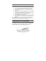
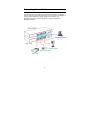
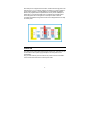
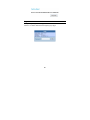
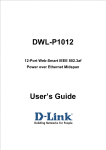
DWL-P1012
12-Port Web-Smart IEEE 802.3af
Power over Ethernet Midspan
Version 1.01
User’s Guide
TABLE OF CONTENTS
About This Guide ...............................................................................................1
Terms...........................................................................................................1
Overview of this User’s Guide...................................................................1
Introduction........................................................................................................1
Features.......................................................................................................2
Ports ............................................................................................................2
Unpacking and Installation ...............................................................................3
Unpacking ...................................................................................................3
Setup............................................................................................................4
Installing the DWL-P1012 on a Desktop ...................................................4
Installing the DWL-P1012 on a Rack.........................................................5
Connecting Network Cables......................................................................6
Power on .....................................................................................................7
Identifying External Components.....................................................................8
Front Panel Components...........................................................................8
Rear Panel ...................................................................................................9
LED Indicators ..........................................................................................10
System LED...............................................................................................10
PoE Port Status LED ................................................................................11
Management Port Status LED .................................................................11
Configuration ...................................................................................................12
Installing the Web Management Utility...................................................12
i
Discovery List ...........................................................................................13
Monitor List ...............................................................................................14
Device Setting...........................................................................................15
Toolbar ......................................................................................................16
Configuring the DWL-P1012 ....................................................................17
Login..........................................................................................................17
Setup Menu ...............................................................................................20
SNMP Setting.....................................................................................21
PoE Setting ........................................................................................25
Schedule ............................................................................................27
Port Group .........................................................................................29
SNTP...................................................................................................31
Device Status.....................................................................................32
System Setting ..................................................................................35
RTC Time............................................................................................36
Trap Setting .......................................................................................38
Set Password.....................................................................................39
Backup Setting ..................................................................................39
Reset Setting .....................................................................................39
Logout ................................................................................................40
WARRANTY ......................................................................................................41
ii
A BOUT T HIS G UIDE
This user’s guide provides instructions and information to aid in the installation
of the DWL-P1012, most importantly how to connect the device to your network.
Terms
For simplicity, this documentation uses the terms “the Midspan” to refer to the
DWL-P1012, and “Midspan” to refer to all Midspan Products, including the
DWL-P1012.
Overview of this User’s Guide
Introduction
Describes the Midspan and its features.
Unpacking and
Setup
Get started with the basic installation of the
Midspan.
Identifying External
Components
Describes the front panel, rear panel, and LED
indicators of the Midspan.
Configure the
Midspan
Configuration of the smart functions of the
Midspan through the web interface.
Warranty
Warranty information and FCC Declaration
I NTRODUCTION
The DWL-P1012 Power over Ethernet Midspan injects power into data-carrying
Ethernet cabling. The Midspan will add power to 12 ports respectively in a
10/100BASE-TX Ethernet network, over TIA/EIA-568 Category 5/5e/6 cabling.
48V DC operating power (up to 15.4W), for data terminal units, is fed over
unused pairs of the cabling (7/8 and 4/5).
The Power over Ethernet Midspan powers PoE capable devices known as
Powered Devices (PD). Devices that are not equipped to receive power over
Ethernet require an external power splitter adapter (DWL-P50) to be powered.
1
Features
The DWL-P1012 features include:
IEEE 802.3af Power over Ethernet compliant.
Provides LED indicator for System and PoE status.
Eliminates the need for AC outlets, local UPS and AC/DC adapters
Web based Management for System and PoE power management.
Supports SNMP protocol version 1
MIB support for:
RFC1213 MIB II.
RFC3621 Power over Ethernet MIB
Private MIB.
Independent overload and short-circuit protection per channel
Standard 19-inch rack mountable.
Ports
Data ports (upper row of ports): Twelve (12) 10/100Mbps Fast Ethernet data
input ports. These ports are designed to carry Ethernet data only (Tx/Rx) over
the standard 2-wire pairs (pins 1/2 and 3/6).
PoE ports (lower row of ports): Twelve (12) 10/100Mbps Fast Ethernet with
48V DC power output ports. These ports are designed to carry Ethernet data
over the standard 2-wire pairs (pins 1/2 and 3/6) and DC power over the spare
pairs (pins 4/5 and 7/8).
Management port: One (1) 10/100Mbps Ethernet/Fast Ethernet port for out of
band management.
2
U NPACKING
AND I NSTALLATION
This chapter provides unpacking and installation information for the DWL-P1012.
Unpacking
Open the shipping carton of the DWL-P1012 and carefully unpack its contents.
The carton should contain the following items:
♦
One DWL-P1012 Web Smart PoE Midspan
♦
Four rubber feet with adhesive backing
♦
One AC power cord
♦
Mounting kit (two brackets and screws)
♦
CD-ROM (This User’s Guide and Utility)
If any item is found missing or damaged, please contact your local reseller for
replacement.
3
Setup
Setup of the DWL-P1012 can be completed easily by following these steps:
Install the Midspan on a sturdy, level surface that can support at least
6.6 lb. (3 kg) of weight. Do not place heavy objects on the device.
The power outlet should be within 1.82 meters (6 feet) of the device.
Visually inspect the power cord and see that it is fully secured to the
AC power port.
Make sure that there is proper heat dissipation from and adequate
ventilation around the Midspan. Leave at least 4 inches (10 cm) of
space at the front and rear of the Midspan for ventilation
Install the Midspan in a fairly cool and dry place for the acceptable
temperature and humidity operating ranges.
Install the Midspan in a site free from strong electromagnetic field
generators (such as motors), vibration, dust, and direct exposure to
sunlight.
When installing the Midspan on a level surface, attach the rubber feet to the
bottom of the device. The rubber feet cushion the Midspan, protect the casing
from scratches and prevent it from scratching other surfaces.
Installing the DWL-P1012 on a Desktop
When installing the DWL-P1012 on a desktop or shelf, the rubber feet included
with the DWL-P1012 should first be attached. Attach these cushioning feet on
the bottom at each corner of the device. Allow enough ventilation space
between the DWL-P1012 and any other objects in the vicinity.
4
Installing the DWL-P1012 on a Rack
The DWL-P1012 can be mounted in a standard 19" rack. Use the following
diagrams to guide you.
Fasten the mounting brackets to the DWL-P1012 using the screws provided.
With the brackets attached securely, you can mount the DWL-P1012 in a
standard rack as shown on the following page.
Mounting the DWL-P1012 in a Standard 19" Rack:
5
Connecting Network Cables
As shown below, the Midspan is connected in series to an Ethernet switch/hub.
The data outputs from the switch are connected to the Midspan. The Midspan
delivers power over spare twisted pairs (pins 7/8 and pins 4/5) of the Category 5
cabling, without degrading the quality of data communications. The
Management port may be connected directly or through a LAN to the
Management station.
6
Each data port is configured as shown below, as data route-through ports for all
data pins (pins 1, 2, 3 and 6). Be certain to use Category 5 or higher cabling to
ensure proper operation. This PoE Midspan is not compatible with Gigabit
Ethernet, any Gigabit Ethernet Capable device will only link at 100Mbps Full
Duplex when connected to the DWL-P1012. IEEE 802.3af compliant Power
Source Equipment will not energize the unused pairs unless an 802.3af
compliant Powered Device signals the Power Source Equipment that it is ready
to receive power.
Power on
The DWL-P1012 must be used with AC power sources 100 - 240 VAC, 50 - 60
Hz. The DWL-P1012’s power supply will adjust to the local power source
automatically.
Plug one end of the PC power cord into the AC power connector of the DWLP1012 and the other end into the local AC power outlet.
7
I DENTIFYING E XTERNAL C OMPONENTS
This chapter describes the front panel, rear panel and LED indicators of the
DWL-P1012.
Front Panel Components
The front panel of the DWL-P1012 consists of twelve (12) 10/100Mbps Fast
Ethernet data ports (data only), twelve (12) 10/100Mbps Fast Ethernet PoE
ports (data + DC power), one (1) 10/100Mbps Ethernet/Fast Ethernet port for
out of band management and a Reset button.
Data port (upper row of ports): Twelve 10/100Mbps Fast Ethernet data ports.
PoE port (lower row of ports): Twelve 10/100Mbps Fast Ethernet data with
DC power output ports.
Management port: One 10/100Mbps Fast Ethernet out of band management
port.
LED Indicators: Comprehensive LED indicators that display the conditions of
the DWL-P1012 and status of the network. A description of these LED indicators
follows.
Reset button: The Reset button is to reset all device settings back to factory
defaults.
Note: The Midspan supports PoE port priority management. When the available
system power is less than required by the PD, the Midspan will enforce PoE port
priority management where the lower port number will have higher priority than
the higher port number, Port 1 > Port 2 > … > Port 12. This means that a device
connected to Port 1 will receive Power before a device connected to Port 2. Be
sure to create a configuration backup once the device configuration is complete.
In the event of an accidental reset the backup can be loaded through the WebUI or Web Smart Utility to save time.
8
Rear Panel
The rear panel of the DWL-P1012 contains an AC power connector.
The AC power connector is a standard three-pronged connector that supports
the AC power cord. Plug in the female connector of the provided power cord into
this socket, and the male side of the cord into a power outlet. The DWL-P1012
automatically adjusts its power setting to any supply voltage in the range from
100 ~ 240 VAC at 50 ~ 60 Hz.
9
LED Indicators
The LED indicators of the DWL-P1012 include Power, CPU, PoE status and
Management port status. Refer to the appropriate section below for information
on LED function and indication.
System LED
Power (PWR)
On (green) : This LED will light green after the Midspan is powered on to
indicate the ready state of the device.
Off
: When the Midspan is powered off or the power cord has an
improper connection.
Power Maximum (PWR MAX)
On
Off
: When the PoE remaining system power <= 15.4W (system
power consumption >= 185W), the system will not provide
power to any additional PoE PD inserted.
: When the system has enough remaining power (greater than
15.4W).
CPU
Blinking
On/Off
: When the CPU is working properly.
: Possible Device Failure, please contact Technical Support.
10
PoE Port Status LED
PoE Status
Green
Red
Off
: When a PoE powered device (PD) is connected and the port
is supplying power normally.
: When the PoE port fails in the following manner:
PoE power circuit shortage.
Power over current: over the power current of PD’s
classification.
Out of PoE voltage of 44 ~ 57 VDC output.
Cost fail.
: No PoE powered device (PD) connected or device is
unplugged from the PoE output port.
Management Port Status LED
Link/Act (green)
On
Blinking
Off
: When the Link/Act LED lights on, the respective port is
successfully connected to an Ethernet network.
: When the Link/Act LED is blinking, the port is transmitting or
receiving data on the Ethernet network.
: No link.
100M (green)
On
Off
: When the respective port is connected to a 100Mbps Fast
Ethernet network.
: When the respective port is connected to a 10Mbps Ethernet
network.
11
C ONFIGURATION
Through the Web Browser you can configure the DWL-P1012’s PoE power
management configuration.
With the attached Web Management Utility, you can easily discover all DWLP1012 units on the network, assign them IP Addresses, change the
administrative passwords and upgrade firmware.
Installing the Web Management Utility
Follow these instructions to install and use the Web Management utility.
1.
Insert the DWL-P1012 Master CD in the CD-Rom Drive.
2.
Allow the CD to Autorun. From the Autorun menu select the option to
install the utility. Skip to step 4. If the Menu does not automatically appear,
go to the Start menu on the Windows desktop, then choose Run.
3.
In the Run dialog box, type D:\Web Management Utility\setup.exe (D:\
depends where your CD-Rom drive is located) and click OK.
4.
Follow the on-screen instructions to install the utility.
5.
Upon completion, go to Program Files -> web_management_utility and
execute the Web Management utility.
The Web Management Utility is
divided into four sections:
Discovery List, Monitor List,
Device Setting and Toolbar
function. For detailed instructions,
refer to the corresponding section
in the following pages.
12
Discovery List
This is the list where you can discover all the Web management devices on the
network.
By pressing the “Discovery” button, you initiate the discovery process which will
find any available Web Smart devices connected to the same LAN as the PC
running the Utility and list them.
Double click or press the “Add to monitor list” button to transfer a device from
the Discovery List to the Monitor List.
System Term definitions in the Discovery List:
MAC Address: Shows the device MAC Address.
IP Address: Shows the current IP address of the device.
Protocol version: Shows the version of the Utility protocol.
Product Name: Shows the device product name.
System Name: Shows the appointed device system name.
Location: Shows where the device is located.
Trap IP: Shows the SNMP Trap Host IP.
Subnet Mask: Shows the Subnet Mask of the device.
Gateway: Shows the Default Gateway of the device.
13
Monitor List
All Web Smart Devices in the Monitor List can be monitored; you can also
receive SNMP traps and show the status of each device.
System word definitions in the Monitor List:
S: Shows the system symbol of the Web-Smart device,
represent
for device system is not active.
IP Address: Shows the current IP address of the device.
MAC Address: Shows the device MAC Address.
Protocol version: Shows the version of the Utility protocol.
Product Name: Shows the device product name.
System Name: Shows the appointed device system name.
Location: Shows where the device is located.
Trap IP: Shows the IP where the Trap to be sent.
Subnet Mask: Shows the Subnet Mask set of the device.
Gateway: Shows the Gateway set of the device.
View Trap: The Trap function can receive and display the events that issue
SNMP traps from the DWL-P1012 in the Monitor List.
There is an indicator light on the “View Trap” button. When this indicator is
green, there is no new trap message. When the indicator is red, a new trap has
been issued, this is to remind us to view the trap.
When the “View Trap” button is clicked, a Trap Information window will pop out
that shows the trap information including Symbol, Time, Device IP and the
Event occurred.
14
The symbol “ ” represents a new trap signal has arisen, this symbol will
disappear after you review and click on the event record.
Add Item: To add a device to the Monitor List manually, enter the IP Address of
the device that you want to monitor.
Delete Item: To delete the device in the Monitor List.
Note: In order to receive Trap information using the utility, the DWL-P1012 has
to be configured with the appropriate Trap IP and Trap Events first.
Device Setting
You may configure the device by using the function key in the Device Setting
Dialog box.
Configuration Setting: In the Configuration Setting, you may configure the IP
Address, Subnet Mask, Default Gateway, Set Trap to (Trap Host IP Address),
System name and Location.
Select the device in the Discovery list or Monitor List and press this button, then
the Configuration Setting window will pop out as Error! Reference source not
found., after filling up the data that you want to change, you must fill up the
password and press the “Set” to process the data changed immediately.
15
Password Change: You can use the Password Change dialog when you need
to change the password. Fill in the new and old passwords and press “Set”
button to apply the password change immediately.
Firmware Upgrade: If D-Link releases firmware to support new functions, the
new firmware can be uploaded through here.
Web Access: Double click the device in the Monitor List or select a device in
the Monitor List and press the “Web Access” button to access the device
through a Web browser.
Toolbar
The toolbar in the Web Management Utility have four main tabs: File, View,
Options and Help.
16
In the “File TAB”, the choices are Monitor Save, Monitor Save As, Monitor Load
and Exit.
Monitor Save: To record the setting of the Monitor List to the default, when you
open the Web Management Utility next time, it will auto load the default
recorded setting.
Monitor Save As: To record the setting of the Monitor List in appointed
filename and file path.
Monitor Load: To manually load the setting file of the Monitor List.
Exit: To exit the Web Management Utility.
In the “View TAB”, the choices are view log and clear log functions, these
functions help monitor and maintain SNMP Trap events.
View Log: To show the event of the Web Management Utility and the device.
Clear Log: to clear the log.
In the “Option TAB”, the choices are Refresh Time function, this function helps
you to refresh the time of monitoring the device. Select 15 seconds, 30 seconds,
1 min, 2 min and 5 min to configure the time of monitoring.
In the “Help TAB”, there is an About function, it will show the version of the Web
Management Utility.
Configuring the DWL-P1012
The DWL-P1012 has a Web GUI interface for smart function configurations. The
DWL-P1012 may be configured through a Web Browser or using the Web
Smart Utility. A network administrator can manage, control and monitor the
DWL-P1012 from the local LAN. This section indicates how to configure the
Midspan to enable its smart functions including: SNMP Setting, PoE Setting,
Schedule and Grouping, SNTP Settings, System Setting, Device status,
and RTC settings.
Login
Prior to configuration of the DWL-P1012, take note that the DWL-P1012 must
be configured through an Ethernet connection. Make sure the manager PC is
17
set on the same IP network. For example, the default IP address of the DWLP1012 is 192.168.0.1, so the manager PC should be set at 192.168.0.x (where
x is a number between 2 and 254), and the default subnet mask is
255.255.255.0.
Open a Java-enabled Web Browser, preferably Internet Explorer 6.0 or above.
Enter the DWL-P1012 IP address http://192.168.0.1 (the factory-default IP
address setting) in the address bar location. Alternatively through the Web
Management Utility, you do not need to remember the IP Address, simply select
the device shown in the Monitor List of the Web Management Utility to access
the device through a Web Browser.
When the following dialog page appears, enter the default password "admin"
and press Login to access the main configuration window.
After entering the correct password, the main page should load where the
device status will be displayed.
18
19
Setup Menu
When the main page appears, locate the Setup menu on the left side of the
screen (see Below). Click on the setup item that you want to configure or
monitor. There are eight options: SNMP, PoE, Schedule, Port Group, SNTP,
Status, System, RTC Time, Trap, Password, Backup Settings and Reset
Settings as shown in the Main Menu screen.
20
SNMP Setting
Simple Network Management Protocol (SNMP) is an OSI Layer 7 (Application
Layer) designed specifically for managing and monitoring network devices.
SNMP enables network management stations to read and modify the settings of
gateways, routers, switches, and other network devices. Use SNMP to
configure the DWL-P1012 features for proper operation, monitor and detect
potential problems in the DWL-P1012, switch, switch group or network.
Managed devices that support SNMP include software (referred to as an agent),
which runs locally on the device. A defined set of variables (managed objects) is
maintained by the SNMP agent and used to manage the device. These objects
are defined in a Management Information Base (MIB), which provides a
standard presentation of the information controlled by the on-board SNMP
agent. SNMP defines both the format of the MIB specifications and the protocol
used to access this information over the network.
The DWL-P1012 supports SNMP version 1. In SNMP v.1, user authentication is
accomplished using 'community strings', which function like passwords. The
remote user SNMP application and the DWL-P1012 SNMP must use the same
community string. SNMP packets from any station that have not been
authenticated are ignored (dropped).
The default community strings for the DWL-P1012 used for SNMP v.1
management access are:
public - Allows authorized management stations to retrieve MIB objects.
private - Allows authorized management stations to retrieve and modify MIB
objects.
Traps
Traps are messages that alert network personnel of events that occur on the
DWL-P1012. The events can range from System Start to PoE port status
change. The DWL-P1012 generates traps and sends them to the trap recipient
(or network manager). Typical traps include trap messages for Device boot up,
Authentication Failure and PoE status change.
21
MIBs
Management and counter information are stored by the Midspan in the
Management Information Base (MIB). The DWL-P1012 uses the standard MIBII Management Information Base module and Power over Ethernet MIB
(RFC3621). Consequently, values for MIB objects can be retrieved from any
SNMP-based network management software. In addition, the DWL-P1012 also
supports its own proprietary enterprise MIB as an extended Management
Information Base. The proprietary MIB may also be retrieved by specifying the
MIB Object Identifier. MIB values can be either read-only or read-write.
Enabled / Disabled: To enable or disable the SNMP function of the DWLP1012.
SNMP Community / Trap: To configure the SNMP Community or SNMP Trap
Host.
Configure SNMP Community:
Add Group: To add an SNMP Community group, press “Add Group” button. In
the Add SNMP Community configuration window fill in the community name and
assign the community enable read_only or read_write access. Press “Apply”
button to save the configuration.
22
Delete Group: To delete a previously defined SNMP Community group, press
“Delete Group” button, the Delete SNMP Community configuration window will
pop out; check the delete dialog box. Press “Apply” to delete the selected
SNMP Community Group.
Modify Group: To modify a previously defined SNMP Community group, click
on the ID parameter to enter to the selected SNMP Community Group and
configure its community name and community enable. Press “Apply” to save the
changes to the SNMP Community Group.
Configure SNMP Trap:
Trap authentication fail: When checked the Midspan will issue an SNMP Trap
in the event of a failed login attempt.
Add Trap: To create a recipient of SNMP traps generated by the DWL-P1012’s
SNMP agent, press “Add Trap” button. In the SNMP Trap Set window fill in the
community name and trap IP address of the remote management station that
will serve as the SNMP host for the Midspan and check the events selection to
enable selected event traps.
23
System Events: Monitoring the system’s status.
Device Bootup: a trap when booting up the system.
Illegal Login: a trap when an incorrect password is use in a login attempt. The
IP address of the source will be recorded.
PoE Events: Monitoring the PoE ports status.
PoE Power fail: a trap when the port’s power source is fail.
Power on/Power off: a trap when the PoE port’s power is on and down.
Power over current: a trap when the PoE port’s power is over current.
Power short circuit: a trap when the PoE port’s power circuit was short.
Power threshold above/below: a trap when the Midspan’s system usage over
80% or below from 80%, the system power budget.
Delete Trap: To delete a previously defined SNMP Trap, Press the “Delete
Trap” button. In the SNMP Trap Delete configuration window select the check
box of the corresponding SNMP Trap that you wish to delete, then click Apply.
24
Modify Trap: To modify a previously defined SNMP Trap, click on the ID
parameter to enter the selected SNMP Trap to configure its community name,
IP address and events. Press “Apply” to save changes.
PoE Setting
The PoE Setting screen shows the status of all PoE ports including PoE Enable,
Power limit, Power current (Watt.), Power Voltage (V), Power current (mA.),
Classification, Status, System budget power, Support total power, Remainder
Power, The ratio of system power supply.
Note: The PoE Status information of Power current, Power Voltage and Current
are instantaneous values. Please “Refresh” the browser window to renew the
information.
25
POE Port Status:
Select “POE Port Status” to configure the PoE Port setting.
To configure the settings, select a value from the drop down box corresponding
to each feature.
Poe Enable: Select to enable or disable the PoE function.
Power limit: This function allows one to manually set a port power current
limitation to be given to the PD, to protect the DWL-P1012 and the connected
device, the power limit function will disable the PoE function of the port when
the power is over loaded. Select “<5W”, “<10W”, “<14W” and “Auto” for the
power limit, “Auto” will follow the classification from the PD for power current.
26
POE System Setting:
Select “POE System Setting” to configure the PoE System setting.
System power Threshold: When the percentage of power being supplied is
greater than or equal to the System Power Threshold, the DWL-P1012 will issue
an SNMP trap to alert the administrator.
Note: When the available system power is less than the PD requests, the
Midspan will enforce PoE port priority management, the numerically lower port
number will have a higher priority than the numerically higher port number, Port
1 > Port 2 > … > Port 12.
Schedule
The DWL-P1012 is capable of enabling and disabling power to each port based
on a recurring schedule that may be defined using the Schedule page of the
Web UI. Scheduling must be used in conjunction with Port Grouping in order to
function properly. Schedule profiles defined in this section can later be applied
to one or more Port Groups for easy administration.
27
To add a schedule profile simply click the Add button and define the parameters
of the desired schedule. To modify an existing schedule profile click on the ID
number next to the schedule profile to be modified.
Name: Enter a friendly name for the schedule to be defined.
Active Type: Select ‘Time Setting’ to define a begin and end date to the
schedule profile. Select ‘Always Active’ to configure the schedule profile without
begin and end date restrictions.
Active From: Configure the begin date and time of the schedule profile (only
applies to ‘Time Setting’ schedule profiles).
Active To: Configure the end date and time of the schedule profile (only applies
to ‘Time Setting’ schedule profiles).
Day/Time Grid: Select the hours during which the PoE port should be active
during each day of the week respectively. The first checkbox in each row
represents 12:00am to 12:59am, the second checkbox in each row represents
1:00am to 1:59am, all the way to the last checkbox represents 11:00pm to
11:59pm. Select the ‘All’ checkbox to enable the entire row.
28
Port Group
The advanced scheduling features of the DWL-P1012 rely on a port grouping
mechanism that allows one to define groups of PoE ports. These groups are
then assigned to a specific schedule profile which all members of that group
adhere to. The default group cannot be modified or deleted and is assigned to
the ‘Always Active’ schedule profile. Up to 6 custom groups may be defined
each with its own corresponding schedule profile. This allows system
administrators to control when their PoE equipment is powered on or off by the
hour seven days a week. Each port may only be a member of a single group, to
change a ports group memebership first remove it from its current group, then
add it to the destination group.
To add a new group, click ‘Add Group.’ To modify an existing group, click on
the corresponding ID number.
Description: Enter a short name for the group (8 characters max)
Schedule: Select the appropriate schedule from the drop down box.
Port: Check the Checkbox of each port you want to be a member of that group.
Each port may only be a member of one custom group.
29
Click ‘Delete Group’ to remove an entire group.
Select the check box next to the group to be deleted and click ‘Apply’ to remove.
30
SNTP
The DWL-P1012 is capable of updating the system time using the Simple
Network Time Protocol. When a valid DNS Server address is configured the
DWL-P1012 can resolve DNS names for time servers prior to synchronization.
From the SNTP configuration page of the Web UI, select SNTP Server Setting
to manage the list of NTP servers used to synchronize. Select SNTP Time
Zone & DST to configure the Time Zone the midspan is located in and enable
Daylight Savings Time if desired.
To add a time server IP or DNS name, click ‘Add Server.’
Server IP: Enter an IPv4 address or Fully Qualified Domain Name of a time
server with which the midspan will update. Click ‘Apply’ to save.
To remove a time server from the list, click ‘Delete Server.’
Check the checkbox of the time server you would like to remove from the list.
Click ‘Apply’ to save.
31
Device Status
Click on the “Status” hyperlink to display the device status on this screen, it will
show the System Status, SNMP Settings, PoE Status, Schedule Profiles, Port
Grouping, SNTP Server and Daylight Savings Time info. This page will load
upon a successful login to the WebUI.
System Status
SNMP Settings
32
PoE Status
Schedule Profiles
Port Group
SNTP Server
33
SNTP Time Zone and DST
Press “Refresh” when you need to renew the posted information.
34
System Setting
The System Setting includes the Web Server Port, System name, Location
name, Login Timeout, IP Address, Subnet Mask, Gateway and DNS IP
addresses. Through the Web Management Utility, you can easily recognize the
device by using the System Name and the Location Name.
The Login Timeout for the management interface is to set the idle time-out for
security reasons, when there is no activity for the specified period of time during
a log-in session, the session will expire and you must log-in again to access the
Web-based Configuration.
Specify the IP Address, Subnet Mask, Default Gateway, and DNS Server
address for the device. Click Apply.
35
RTC Time
The DWL-P1012 includes an integrated Real Time Clock to handle timekeeping duties in order for port scheduling to properly function. The time may
be set using one of three methods: Manual Configuration, PC Time, and SNTP
Synchronization.
To manually configure the System Time select the year, month, and day from
the appropriate drop down. Select the hour (in 24-hour notation), minute and
second and click the ‘Set Time’ button to apply the changes.
To use the time and date of the PC from which you are configuring the Midspan,
select ‘PC Time’ from the drop down menu. The time and date from the
computer being used to configure the DWL-P1012 will automatically update in
the appropriate fields. Click ‘Set Time’ to apply the changes.
36
To synchronize the DWL-P1012 with an NTP server to retrieve the current time
and date select ‘SNTP Time’ from the drop down menu. The DWL-P1012 will
then contact the first SNTP server in the time server list in a top-down order to
update the system time. The correct time should appear in the appropriate
fields. Click the ‘Set Time’ button to apply changes.
37
Trap Setting
The Trap Setting enables the DWL-P1012 to monitor the selected Events
through the Web Management Utility, configure the Trap IP Address of the
manager where the trap should be sent.
System Events: Monitoring the system’s Status.
Device Bootup: a trap when booting up the system.
Illegal Login: a trap when a wrong password is used in a login attempt. The IP
address of the source will be recorded.
PoE Events: Monitoring the PoE ports status.
PoE Power fail: a trap when the port’s power source has failed.
Power on/Power off: a trap when the PoE port’s power is on and down.
Power over current: a trap when the PoE port’s power is over current.
Power short circuit: a trap when the PoE port’s power circuit was short.
38
Set Password
A password is an invaluable tool for the manager to secure the management
interface of the DWL-P1012, use this function to change the password.
If you forget the password, press the “Reset” button in the front panel of the
DWL-P1012 for 10-15 Seconds. All current settings such as Port Settings,
SNMP, etc. will be lost and the DWL-P1012 will be restored to the factory
default settings.
Backup Setting
The backup tools allow one to create backup files of current settings of the
DWL-P1012. To generate a configuration backup file, press the “Backup” button.
To restore a configuration backup file to the device, browse to the location of the
backup file on the local Hard Drive and press the “Restore” button to reconfigure
with the settings of the recorded file.
Note: when restoring a backup configuration file, the current admin password
will not be erased.
Reset Setting
The Factory Reset button will reset the device back to factory default settings.
Be aware that all configuration data will be lost, and the IP address of the device
will revert to the default value of 192.168.0.1.
39
Logout
Clicking the logout Hyperlink will log you out of the web-based administrative
interface. You will be redirected to the beginning log-in page.
40
WARRANTY
Subject to the terms and conditions set forth herein, D-Link Systems, Inc. (“DLink”) provides this Limited warranty for its product only to the person or entity
that originally purchased the product from:
D-Link or its authorized reseller or distributor and
Products purchased and delivered within the fifty states of the United States, the
District of Columbia, U.S. Possessions or Protectorates, U.S. Military
Installations, addresses with an APO or FPO.
Limited Warranty: D-Link warrants that the hardware portion of the D-Link
products described below will be free from material defects in workmanship and
materials from the date of original retail purchase of the product, for the period
set forth below applicable to the product type (“Warranty Period”), except as
otherwise stated herein.
1-Year Limited Warranty for the Product(s) is defined as follows:
Hardware (excluding power supplies and fans) One (1) Year
Power Supplies and Fans One (1) Year
Spare parts and spare kits Ninety (90) days
D-Link’s sole obligation shall be to repair or replace the defective Hardware
during the Warranty Period at no charge to the original owner or to refund at DLink’s sole discretion. Such repair or replacement will be rendered by D-Link at
an Authorized D-Link Service Office. The replacement Hardware need not be
new or have an identical make, model or part. D-Link may in its sole discretion
replace the defective Hardware (or any part thereof) with any reconditioned
product that D-Link reasonably determines is substantially equivalent (or
superior) in all material respects to the defective Hardware. Repaired or
replacement Hardware will be warranted for the remainder of the original
Warranty Period from the date of original retail purchase. If a material defect is
incapable of correction, or if D-Link determines in its sole discretion that it is not
practical to repair or replace the defective Hardware, the price paid by the
original purchaser for the defective Hardware will be refunded by D-Link upon
return to D-Link of the defective Hardware. All Hardware (or part thereof) that is
replaced by D-Link, or for which the purchase price is refunded, shall become
the property of D-Link upon replacement or refund.
41
Limited Software Warranty: D-Link warrants that the software portion of the
product (“Software”) will substantially conform to D-Link’s then current functional
specifications for the Software, as set forth in the applicable documentation,
from the date of original retail purchase of the Software for a period of ninety (90)
days (“Warranty Period”), provided that the Software is properly installed on
approved hardware and operated as contemplated in its documentation. D-Link
further warrants that, during the Warranty Period, the magnetic media on which
D-Link delivers the Software will be free of physical defects. D-Link’s sole
obligation shall be to replace the non-conforming Software (or defective media)
with software that substantially conforms to D-Link’s functional specifications for
the Software or to refund at D-Link’s sole discretion. Except as otherwise
agreed by D-Link in writing, the replacement Software is provided only to the
original licensee, and is subject to the terms and conditions of the license
granted by D-Link for the Software. Software will be warranted for the
remainder of the original Warranty Period from the date or original retail
purchase. If a material non-conformance is incapable of correction, or if D-Link
determines in its sole discretion that it is not practical to replace the nonconforming Software, the price paid by the original licensee for the nonconforming Software will be refunded by D-Link; provided that the nonconforming Software (and all copies thereof) is first returned to D-Link. The
license granted respecting any Software for which a refund is given
automatically terminates.
Non-Applicability of Warranty: The Limited Warranty provided hereunder for
hardware and software of D-Link's products will not be applied to and does not
cover any refurbished product and any product purchased through the inventory
clearance or liquidation sale or other sales in which D-Link, the sellers, or the
liquidators expressly disclaim their warranty obligation pertaining to the product
and in that case, the product is being sold "As-Is" without any warranty
whatsoever including, without limitation, the Limited Warranty as described
herein, notwithstanding anything stated herein to the contrary.
Submitting A Claim: The customer shall return the product to the original
purchase point based on its return policy. In case the return policy period has
expired and the product is within warranty, the customer shall submit a claim to
D-Link as outlined below:
The customer must submit with the product as part of the claim a written
description of the Hardware defect or Software nonconformance in sufficient
detail to allow D-Link to confirm the same.
42
The original product owner must obtain a Return Material Authorization (“RMA”)
number from the Authorized D-Link Service Office and, if requested, provide
written proof of purchase of the product (such as a copy of the dated purchase
invoice for the product) before the warranty service is provided.
After an RMA number is issued, the defective product must be packaged
securely in the original or other suitable shipping package to ensure that it will
not be damaged in transit, and the RMA number must be prominently marked
on the outside of the package. Do not include any manuals or accessories in
the shipping package. D-Link will only replace the defective portion of the
Product and will not ship back any accessories.
The customer is responsible for all in-bound shipping charges to D-Link. No
Cash on Delivery (“COD”) is allowed. Products sent COD will either be rejected
by D-Link or become the property of D-Link. Products shall be fully insured by
the customer and shipped to D-Link Systems, Inc., 17595 Mt. Herrmann,
Fountain Valley, CA 92708. D-Link will not be held responsible for any
packages that are lost in transit to D-Link. The repaired or replaced packages
will be shipped to the customer via UPS Ground or any common carrier
selected by D-Link, with shipping charges prepaid. Expedited shipping is
available if shipping charges are prepaid by the customer and upon request.
D-Link may reject or return any product that is not packaged and shipped in
strict compliance with the foregoing requirements, or for which an RMA number
is not visible from the outside of the package. The product owner agrees to pay
D-Link’s reasonable handling and return shipping charges for any product that is
not packaged and shipped in accordance with the foregoing requirements, or
that is determined by D-Link not to be defective or non-conforming.
What Is Not Covered: This limited warranty provided by D-Link does not cover:
Products, if in D-Link’s judgment, have been subjected to abuse, accident,
alteration, modification, tampering, negligence, misuse, faulty installation, lack
of reasonable care, repair or service in any way that is not contemplated in the
documentation for the product, or if the model or serial number has been altered,
tampered with, defaced or removed; Initial installation, installation and removal
of the product for repair, and shipping costs; Operational adjustments covered
in the operating manual for the product, and normal maintenance; Damage that
occurs in shipment, due to act of God, failures due to power surge, and
cosmetic damage; Any hardware, software, firmware or other products or
services provided by anyone other than D-Link; Products that have been
purchased from inventory clearance or liquidation sales or other sales in which
43
D-Link, the sellers, or the liquidators expressly disclaim their warranty obligation
pertaining to the product. Repair by anyone other than D-Link or an Authorized
D-Link Service Office will void this Warranty.
Disclaimer of Other Warranties: EXCEPT FOR THE LIMITED WARRANTY
SPECIFIED HEREIN, THE PRODUCT IS PROVIDED “AS-IS” WITHOUT ANY
WARRANTY OF ANY KIND WHATSOEVER INCLUDING, WITHOUT
LIMITATION, ANY WARRANTY OF MERCHANTABILITY, FITNESS FOR A
PARTICULAR PURPOSE AND NON-INFRINGEMENT. IF ANY IMPLIED
WARRANTY CANNOT BE DISCLAIMED IN ANY TERRITORY WHERE A
PRODUCT IS SOLD, THE DURATION OF SUCH IMPLIED WARRANTY
SHALL BE LIMITED TO NINETY (90) DAYS. EXCEPT AS EXPRESSLY
COVERED UNDER THE LIMITED WARRANTY PROVIDED HEREIN, THE
ENTIRE RISK AS TO THE QUALITY, SELECTION AND PERFORMANCE OF
THE PRODUCT IS WITH THE PURCHASER OF THE PRODUCT.
Limitation of Liability: TO THE MAXIMUM EXTENT PERMITTED BY LAW, DLINK IS NOT LIABLE UNDER ANY CONTRACT, NEGLIGENCE, STRICT
LIABILITY OR OTHER LEGAL OR EQUITABLE THEORY FOR ANY LOSS OF
USE OF THE PRODUCT, INCONVENIENCE OR DAMAGES OF ANY
CHARACTER, WHETHER DIRECT, SPECIAL, INCIDENTAL OR
CONSEQUENTIAL (INCLUDING, BUT NOT LIMITED TO, DAMAGES FOR
LOSS OF GOODWILL, LOSS OF REVENUE OR PROFIT, WORK STOPPAGE,
COMPUTER FAILURE OR MALFUNCTION, FAILURE OF OTHER
EQUIPMENT OR COMPUTER PROGRAMS TO WHICH D-LINK’S PRODUCT
IS CONNECTED WITH, LOSS OF INFORMATION OR DATA CONTAINED IN,
STORED ON, OR INTEGRATED WITH ANY PRODUCT RETURNED TO DLINK FOR WARRANTY SERVICE) RESULTING FROM THE USE OF THE
PRODUCT, RELATING TO WARRANTY SERVICE, OR ARISING OUT OF
ANY BREACH OF THIS LIMITED WARRANTY, EVEN IF D-LINK HAS BEEN
ADVISED OF THE POSSIBILITY OF SUCH DAMAGES. THE SOLE REMEDY
FOR A BREACH OF THE FOREGOING LIMITED WARRANTY IS REPAIR,
REPLACEMENT OR REFUND OF THE DEFECTIVE OR NON-CONFORMING
PRODUCT. THE MAXIMUM LIABILITY OF D-LINK UNDER THIS WARRANTY
IS LIMITED TO THE PURCHASE PRICE OF THE PRODUCT COVERED BY
THE WARRANTY. THE FOREGOING EXPRESS WRITTEN WARRANTIES
AND REMEDIES ARE EXCLUSIVE AND ARE IN LIEU OF ANY OTHER
WARRANTIES OR REMEDIES, EXPRESS, IMPLIED OR STATUTORY
Governing Law: This Limited Warranty shall be governed by the laws of the
State of California. Some states do not allow exclusion or limitation of incidental
44
or consequential damages, or limitations on how long an implied warranty lasts,
so the foregoing limitations and exclusions may not apply. This limited warranty
provides specific legal rights and the product owner may also have other rights
which vary from state to state.
Trademarks: D-Link is a registered trademark of D-Link Systems, Inc. Other
trademarks or registered trademarks are the property of their respective
manufacturers or owners.
Copyright Statement: No part of this publication or documentation
accompanying this Product may be reproduced in any form or by any means or
used to make any derivative such as translation, transformation, or adaptation
without permission from D-Link Corporation/D-Link Systems, Inc., as stipulated
by the United States Copyright Act of 1976. Contents are subject to change
©
without prior notice. Copyright 2005 by D-Link Corporation/D-Link Systems,
Inc. All rights reserved.
CE Mark Warning: This is a Class A product. In an Industrial environment, this
product may cause radio interference, in which case the user may be required
to take adequate measures.
FCC Statement: This equipment has been tested and found to comply with the
limits for a Class A digital device, pursuant to part 15 of the FCC Rules. These
45
limits are designed to provide reasonable protection against harmful
interference in an industrial installation. This equipment generates, uses, and
can radiate radio frequency energy and, if not installed and used in accordance
with the instructions, may cause harmful interference to radio communication.
However, there is no guarantee that interference will not occur in a particular
installation. If this equipment does cause harmful interference to radio or
television reception, which can be determined by turning the equipment off and
on, the user is encouraged to try to correct the interference by one or more of
the following measures:
Reorient or relocate the receiving antenna.
Increase the separation between the equipment and receiver.
Connect the equipment into an outlet on a circuit different from that to
which the receiver is connected.
Consult the dealer or an experienced radio/TV technician for help.
For detailed warranty outside the United States, please contact
corresponding local D-Link office.
46
Technical Support
You can find software updates and user documentation on the DLink website.
D-Link provides free technical support for customers within the
United States and within Canada for the duration of the warranty
period on this product.
U.S. and Canadian customers can contact D-Link technical support
through our website, or by phone.
Tech Support for customers within the United States:
D-Link Technical Support over the Telephone:
(877) 453-5465
Monday through Friday 6:00am to 6:00pm PST
D-Link Technical Support over the Internet:
http://support.dlink.com
e-mail: [email protected]
Tech Support for customers within the Canada:
D-Link Technical Support over the Telephone:
(800) 361-5265
Monday through Friday 7:30am to 9:00pm EST
D-Link Technical Support over the Internet:
http://support.dlink.ca
e-mail: [email protected]
47