1
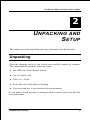
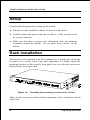
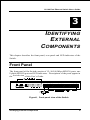
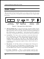
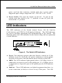
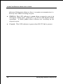
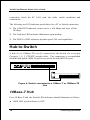
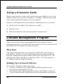
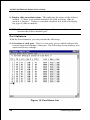
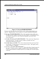
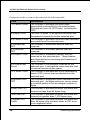
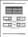
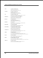
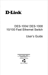
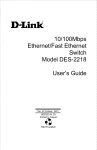
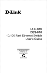
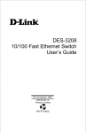
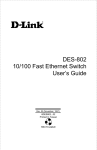
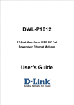
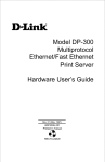
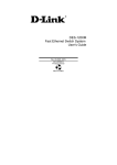
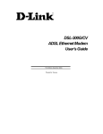
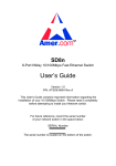
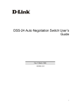
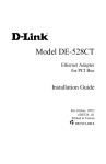
DES-1012
10/100 Fast Ethernet Switch
User’s Guide
Rev. 01 (January, 1998)
6DES1012..01
Printed In Taiwan
RECYCLABLE
Wichtige Sicherheitshinweise
1.
Bitte lesen Sie sich diese Hinweise sorgfältig durch.
2.
Heben Sie diese Anleitung für den spätern Gebrauch auf.
3.
Vor jedem Reinigen ist das Gerät vom Stromnetz zu trennen. Vervenden Sie keine Flüssig- oder
Aerosolreiniger. Am besten dient ein angefeuchtetes Tuch zur Reinigung.
4.
Um eine Beschädigung des Gerätes zu vermeiden sollten Sie nur Zubehörteile verwenden, die vom
Hersteller zugelassen sind.
5.
Das Gerät is vor Feuchtigkeit zu schützen.
6.
Bei der Aufstellung des Gerätes ist auf sichern Stand zu achten. Ein Kippen oder Fallen könnte
Verletzungen hervorrufen. Verwenden Sie nur sichere Standorte und beachten Sie die Aufstellhinweise des
Herstellers.
7.
Die Belüftungsöffnungen dienen zur Luftzirkulation die das Gerät vor Überhitzung schützt. Sorgen Sie
dafür, daß diese Öffnungen nicht abgedeckt werden.
8.
Beachten Sie beim Anschluß an das Stromnetz die Anschlußwerte.
9.
Die Netzanschlußsteckdose muß aus Gründen der elektrischen Sicherheit einen Schutzleiterkontakt haben.
10. Verlegen Sie die Netzanschlußleitung so, daß niemand darüber fallen kann. Es sollete auch nichts auf der
Leitung abgestellt werden.
11. Alle Hinweise und Warnungen die sich am Geräten befinden sind zu beachten.
12. Wird das Gerät über einen längeren Zeitraum nicht benutzt, sollten Sie es vom Stromnetz trennen. Somit
wird im Falle einer Überspannung eine Beschädigung vermieden.
13. Durch die Lüftungsöffnungen dürfen niemals Gegenstände oder Flüssigkeiten in das Gerät gelangen. Dies
könnte einen Brand bzw. Elektrischen Schlag auslösen.
14. Öffnen Sie niemals das Gerät. Das Gerät darf aus Gründen der elektrischen Sicherheit nur von
authorisiertem Servicepersonal geöffnet werden.
15. Wenn folgende Situationen auftreten ist das Gerät vom Stromnetz zu trennen und von einer qualifizierten
Servicestelle zu überprüfen:
a – Netzkabel oder Netzstecker sint beschädigt.
b – Flüssigkeit ist in das Gerät eingedrungen.
c – Das Gerät war Feuchtigkeit ausgesetzt.
d – Wenn das Gerät nicht der Bedienungsanleitung ensprechend funktioniert oder Sie mit Hilfe dieser
Anleitung keine Verbesserung erzielen.
e – Das Gerät ist gefallen und/oder das Gehäuse ist beschädigt.
f – Wenn das Gerät deutliche Anzeichen eines Defektes aufweist.
16. Bei Reparaturen dürfen nur Orginalersatzteile bzw. den Orginalteilen entsprechende Teile verwendet
werden. Der Einsatz von ungeeigneten Ersatzteilen kann eine weitere Beschädigung hervorrufen.
17. Wenden Sie sich mit allen Fragen die Service und Repartur betreffen an Ihren Servicepartner. Somit
stellen Sie die Betriebssicherheit des Gerätes sicher.
Limited Warranty
Hardware:
D-Link warrants its hardware products to be free from defects in workmanship and materials, under normal use
and service, for the following periods measured from date of purchase from D-Link or its Authorized Reseller:
Product Type
Complete products
Spare parts and spare kits
Warranty Period
One year
90 days
Your dealer, or your nearest D-Link office, can advise
whether a longer period of warranty applies to your
purchase, and if so, can provide you a separate certificate
of supplemental warranty.
The one-year period of warranty on complete products (or such longer period of warranty as may be offered as
to your purchase) applies on condition that the product's Registration Card is filled out and returned to a D-Link
office within ninety (90) days of purchase. A list of D-Link offices is provided at the back of this manual,
together with a copy of the Registration Card. Failing such timely registration of purchase, the warranty period
shall be limited to ninety (90) days.
If the product proves defective within the applicable warranty period, D-Link will provide repair or replacement
of the product. D-Link shall have the sole discretion whether to repair or replace, and replacement product may
be new or reconditioned. Replacement product shall be of equivalent or better specifications, relative to the
defective product, but need not be identical. Any product or part repaired by D-Link pursuant to this warranty
shall have a warranty period of not less than 90 days, from date of such repair, irrespective of any earlier
expiration of original warranty period. When D-Link provides replacement, then the defective product becomes
the property of D-Link.
Warranty service may be obtained by contacting a D-Link office within the applicable warranty period, and
requesting a Return Material Authorization (RMA) number. If a Registration Card for the product in question
has not been returned to D-Link, then a proof of purchase (such as a copy of the dated purchase invoice) must
be provided. If Purchaser's circumstances require special handling of warranty correction, then at the time of
requesting RMA number, Purchaser may also propose special procedure as may be suitable to the case.
After an RMA number is issued, the defective product must be packaged securely in the original or other
suitable shipping package to ensure that it will not be damaged in transit, and the RMA number must be
prominently marked on the outside of the package. The package must be mailed or otherwise shipped to D-Link
with all costs of mailing/shipping/insurance prepaid; D-Link will ordinarily reimburse Purchaser for
mailing/shipping/insurance expenses incurred for return of defective product in accordance with this warranty.
D-Link shall never be responsible for any software, firmware, information, or memory data of Purchaser
contained in, stored on, or integrated with any product returned to D-Link pursuant to this warranty.
Any package returned to D-Link without an RMA number will be rejected and shipped back to Purchaser at
Purchaser's expense, and D-Link reserves the right in such a case to levy a reasonable handling charge in
addition mailing or shipping costs.
Software:
Warranty service for software products may be obtained by contacting a D-Link office within the applicable
warranty period. A list of D-Link offices is provided at the back of this manual, together with a copy of the
Registration Card. If a Registration Card for the product in question has not been returned to a D-Link office,
then a proof of purchase (such as a copy of the dated purchase invoice) must be provided when requesting
warranty service. The term "purchase" in this software warranty refers to the purchase transaction and resulting
licence to use such software.
D-Link warrants that its software products will perform in substantial conformance with the applicable product
documentation provided by D-Link with such software product, for a period of ninety (90) days from the date of
purchase from D-Link or its Authorized Reseller. D-Link warrants the magnetic media, on which D-Link
provides its software product, against failure during the same warranty period. This warranty applies to
purchased software, and to replacement software provided by D-Link pursuant to this warranty, but shall not
apply to any update or replacement which may be provided for download via the Internet, or to any update
which may otherwise be provided free of charge.
D-Link's sole obligation under this software warranty shall be to replace any defective software product with
product which substantially conforms to D-Link's applicable product documentation. Purchaser assumes
responsibility for the selection of appropriate application and system/platform software and associated reference
materials. D-Link makes no warranty that its software products will work in combination with any hardware, or
any application or system/platform software product provided by any third party, excepting only such products
as are expressly represented, in D-Link's applicable product documentation as being compatible. D-Link's
obligation under this warranty shall be a reasonable effort to provide compatibility, but D-Link shall have no
obligation to provide compatibility when there is fault in the third-party hardware or software. D-Link makes no
warranty that operation of its software products will be uninterrupted or absolutely error-free, and no warranty
that all defects in the software product, within or without the scope of D-Link's applicable product
documentation, will be corrected.
D-Link Offices for Registration and Warranty Service
The product's Registration Card, provided at the back of this manual, must be sent to a D-Link office. To obtain
an RMA number for warranty service as to a hardware product, or to obtain warranty service as to a software
product, contact the D-Link office nearest you. An addresses/
telephone/fax list of D-Link offices is provided in the back of this manual.
Trademarks
All rights reserved, contents subject to change without prior notice.
Ethernet is a trademark of Xerox Corporation.
Microsoft Windows is a trademark of Microsoft Corporation.
All other trademarks belong to their respective proprietors.
FCC Warning
This equipment has been tested and found to comply with the limits for a
Class A digital device, pursuant to Part 15 of the FCC Rules. These limits are
designed to provide reasonable protection against harmful interference when
the equipment is operated in a commercial environment. This equipment
generates, uses, and can radiate radio frequency energy and, if not installed
and used in accordance with this user’s guide, may cause harmful interference
to radio communications. Operation of this equipment in a residential area is
likely to cause harmful interference in which case the user will be required to
correct the interference at his own expense.
T ABLE OF C ONTENTS
0 ABOUT THIS GUIDE ............................................................................. ix
PURPOSE ...................................................................................................... ix
TERMS/USAGE ............................................................................................. ix
OVERVIEW OF THIS USER'S GUIDE ............................................................... ix
1 INTRODUCTION ..................................................................................... 1
FAST ETHERNET TECHNOLOGY ..................................................................... 1
SWITCHING TECHNOLOGY............................................................................. 2
FEATURES ..................................................................................................... 3
Performance Features .............................................................................. 4
2 UNPACKING AND SETUP .................................................................... 5
UNPACKING .................................................................................................. 5
SETUP ........................................................................................................... 6
RACK INSTALLATION .................................................................................... 6
POWER ON .................................................................................................... 7
LED Indicators ......................................................................................... 7
Power Failure ........................................................................................... 8
3 IDENTIFYING EXTERNAL COMPONENTS...................................... 9
FRONT PANEL ............................................................................................... 9
REAR PANEL ............................................................................................... 10
LED INDICATORS ....................................................................................... 11
4 CONNECTING THE SWITCH............................................................. 13
PC TO SWITCH ............................................................................................ 13
HUB TO SWITCH .......................................................................................... 14
10Base-T Hub ......................................................................................... 15
100Base-TX Hub..................................................................................... 15
HUB WITHOUT UPLINK (MDI-II) PORT ........................................................ 15
Using a Straight Cable............................................................................ 16
Introduction
vii
10/100 Fast Ethernet Switch User’s Guide
Using a Crossover Cable ........................................................................ 16
CONFIGURING THE PORT SPEED & DUPLEX MODE ..................................... 16
SWITCH TO SWITCH (OTHER DEVICES) ....................................................... 17
Using a Straight Cable............................................................................ 18
Using a Crossover Cable ........................................................................ 18
CONSOLE MANAGEMENT PROGRAM ........................................................... 19
Overview ................................................................................................. 19
Setting Up a Console Device .................................................................. 19
Navigating the Console Program Screens .............................................. 20
Configuring the Console ......................................................................... 22
7 TECHNICAL SPECIFICATIONS ........................................................ 29
8 RJ-45 PIN SPECIFICATION ................................................................ 32
Optional 100BASE-FX MODULE SPECIFICATION ......................... 34
viii
About This Guide
10/100 Fast Ethernet Switch User’s Guide
0 A BOUT T HIS G UIDE
Congratulations on your purchase of DES-1012 Fast Ethernet Switch. This
device integrates 100Mbps Fast Ethernet and 10Mbps Ethernet network
capabilities in a highly flexible desktop package.
Purpose
This manual discusses how to install your DES-1012 Fast Ethernet Switch.
Terms/Usage
For simplicity, this documentation uses the terms “Switch” (first letter upper
case) to refer to your DES-1012 Fast Ethernet Switch, and “switch” (first
letter lower case) to refer to all Ethernet switches, including your DES-1012.
Overview of this User’s Guide
♦ Chapter 1, Introduction. Describes the Switch and its features.
♦ Chapter 2, Unpacking and Setup. Helps you get started with the basic
installation of the Switch.
♦ Chapter 3, Identifying External Components. Describes the front
panel, rear panel and LED indicators of the Switch.
About This Guide
ix
10/100 Fast Ethernet Switch User’s Guide
♦ Chapter 4, Connecting the Switch. Tells how you can connect the
your Switch to your Ethernet network.
♦ Appendix A, Technical Specifications. Lists the technical (general,
physical and environmental, and performance) specifications of the
Switch.
♦
Appendix B, RJ-45 Pin Specification. Describes the RJ-45
receptacle/connector and the straight and crossover cable connector.
♦
Appendix C, Describes the DES-112FX 100BASE-FX Module
Specifications.
x
About This Guide
10/100 Fast Ethernet Switch User’s Guide
4
1 I NTRODUCTION
This section describes the features of the DES-1012, as well as giving some
background information about Ethernet and Fast Ethernet switching
technology.
Fast Ethernet Technology
The growing importance of LANs and the increasing complexity of desktop
computing applications are fueling the need for high performance networks.
A number of high-speed LAN technologies have been proposed to provide
greater bandwidth and improve client/server response times. Among them,
Fast Ethernet, or 100Base-T, provides a non-disruptive, smooth evolution
from the current 10Base-T technology. The non-disruptive and smooth
evolution nature, and the dominating potential market base, virtually
guarantee cost effective and high performance Fast Ethernet solutions in the
years to come.
100Mbps Fast Ethernet is a new standard specified by the IEEE 802.3 LAN
committee. It is an extension of the 10Mbps Ethernet standard with the
ability to transmit and receive data at 100Mbps, while maintaining the
CSMA/CD Ethernet protocol.
Since the 100Mbps Fast Ethernet is
compatible with all other 10Mbps Ethernet environments, it provides a
straightforward upgrade and takes advantage of the company’s existing
investment in hardware, software, and personnel training.
Introduction
1
10/100 Fast Ethernet Switch User’s Guide
Switching Technology
Another approach to pushing beyond the limits of Ethernet technology is the
development of switching technology. A switch bridge's Ethernet packets at
the MAC address level of the Ethernet protocol transmitting among
connected Ethernet or Fast Ethernet LAN segments.
Switching is a cost-effective way of increasing the total network capacity
available to users on a local area network. A switch increases capacity and
decreases network loading by making it possible for a local area network to
be divided into different segments which don’t compete with each other for
network transmission capacity, giving a decreased load on each.
The switch acts as a high-speed selective bridge between the individual
segments.
The switch, without interfering with any other segments
automatically forwards traffic that needs to go from one segment to another.
This allows the total network capacity to be multiplied, while still maintaining
the same network cabling and adapter cards.
For Fast Ethernet networks, a switch is an effective way of eliminating
problems of chaining hubs beyond the two-repeater limit.” A switch can be
used to split parts of the network into different collision domains, making it
possible to expand your Fast Ethernet network beyond the 205-meter network
diameter limit for 100BASE-TX networks. Switches supporting both
traditional 10Mbps Ethernet and 100Mbps Fast Ethernet are also ideal for
bridging between existing 10Mbps networks and new 100Mbps networks.
Switching LAN technology is a marked improvement over the previous
generation of network bridges, which were characterized by higher latencies.
Routers have also been used to segment local area networks, but the cost of a
router and the setup and maintenance required make routers relatively
impractical. Today switches are an ideal solution to most kinds of local area
network congestion problems.
2
Introduction
10/100 Fast Ethernet Switch User’s Guide
Features
The Switch is designed for easy installation and high performance in an
environment where traffic on the network and the number of users increase
continuously.
The Switch with its rack size is specifically designed for network workgroups.
The Switch provides immediate access to a rapidly growing network through
a wide range of user-reliable functions.
The Switch is ideal for deployment with multiple high-speed servers for
shared bandwidth 10Mbps or 100Mbps workgroups. In 200Mbps full-duplex
mode, any port can provide workstations with a congestion-free data pipe for
simultaneous access to the server.
The Switch is expandable by cascading two or more switches together. As all
ports support 200Mbps full duplex, the Switch can be cascaded from any port
and to any number of switches.
The Switch is a perfect choice for site planning to upgrade to Fast Ethernet in
the future. Ethernet workgroups can connect to the Switch now, and change
adapters and hubs anytime later without needing to change the Switch or
reconfigure the network.
The Switch combines dynamic memory allocation with store-and-forward
switching to ensure that the buffer is effectively allocated for each port, while
controlling the data flow between the transmit and receive nodes to guarantee
against all possible packet loss.
Other key features are:
♦ Twelve N-Way UTP/STP ports all come with auto-negotiation and
operate at 10/100 Mbps for connection to servers and hubs. All ports can
be configured for full or half-duplex operation.
♦ Uplink/MDI-II (media dependent interface) port for uplinking to
another switch, hub or repeater. Please note that if you are using the
Introduction
3
10/100 Fast Ethernet Switch User’s Guide
uplink port, you will not be able to use port one (1x) because these
ports are logically connected.
Performance Features
• 10/100Mbps Auto-Negotiation and Auto-Sensing on All Ports
• Full/half duplex operation for each port
• 1.3 Gbps Switching Fabric, Provides Wire-Speed Performance on All
Ports
• Parallel Store-and-forward Architecture Provides High-Speed Switching
scheme
• LEDs for Easy Recognition of the Switch Operating Status
• Optional DMA Port for a 100BASE-FX SC type module (paired with Port
12)
• Console Port for easy Troubleshooting and Management
• Complete Frame Checking & Error Filtering
4
Introduction
10/100 Fast Ethernet Switch User’s Guide
5
2 U NPACKING AND
S ETUP
This chapter provides unpacking and setup information for the Switches.
Unpacking
Open the shipping carton of the Switch and carefully unpack its contents.
The carton should contain the following items:
♦ One DES-1012 Fast Ethernet Switch
♦ One AC power cord
♦ This User’s Guide
♦ Four rubber feet with adhesive backing
♦ Six screws and two L-type brackets for rack mounting
If any item is found missing or damaged, please contact your local Reseller
for replacement.
Unpacking and Setup
5
10/100 Fast Ethernet Switch User’s Guide
Setup
Consider the following when setting up the Switch:
♦ The power outlet should be within 1.82 meters of the device.
♦ Visually inspect the power cord and see that it is fully secured to the
AC power connector.
♦ Make sure that there is proper heat dissipation from and adequate
ventilation around the Switch. Do not place heavy objects on the
Switch.
Rack Installation
The Switch can be mounted in an EIA standard size, 19-inch rack, which can
be placed in a wiring closet with other equipment. To install, attach the
mounting brackets on the switch’s front panel (one on each side) and secure
them with the screws provided.
Figure 1A, Attaching the mounting brackets to the Switch
Then, use the screws provided with the equipment rack to mount the Switch
in the rack.
6
Unpacking and Setup
10/100 Fast Ethernet Switch User’s Guide
Figure 1B, Installing the Switch in an equipment rack
Power On
The Switch can be used with AC power sources 100 to 240 VAC, 50 to 60
Hz. The power switch is located at the rear of the unit adjacent to the AC
power connector and the system fan. To turn the Switch on, press the power
switch to the on or “1” position. The Switch’s power supply will adjust to the
local power source automatically and may be turned on without having any or
all LAN segment cables connected.
LED Indicators
After the switch is turned on, the LED indicators should respond as follows:
♦ The power LED indicator will be green.
Unpacking and Setup
7
10/100 Fast Ethernet Switch User’s Guide
Power Failure
As a precaution, the Switch should be turned OFF in case of a power failure.
Press the power switch to the off or “0” position. When power is resumed,
turn the Switch ON. At all times, avoid leaving the Switch ON after the
occurrence of a power failure.
8
Unpacking and Setup
10/100 Fast Ethernet Switch User’s Guide
6
3 I DENTIFYING
E XTERNAL
C OMPONENTS
This chapter describes the front panel, rear panel and LED indicators of the
Switch.
Front Panel
The front panel of the Switch consists of 12 (10/100 Mbps MDI-X) ports, one
Uplink (MDI-II) port and LED indicators. Descriptions of the ports appear in
the Introduction of this User’s Guide.
Figure2, Front panel view of the Switch
Identifying External Components
9
10/100 Fast Ethernet Switch User’s Guide
Rear Panel
The rear panel of the Switch consists of a power switch, an AC power
connector, a system fan, a location for slide-in module, and a duplex-mode
Dip switch.
Location for
slide-in module
System
Fan
Dip switch for
Duplex mode
AC Power
Connector
Power
switch
Figure 3, Rear panel view of the Switch
♦
Slide-in Module Slot. Use this slot to install a optional 100Base-FX(SC
type) DES-112FX slide-in module. The module can be used to provide a
high speed link to the rest of your network. The detail specification of
this module please see Appendix C. And when the slide-in module is
fitted, port 12 automatically switches to become the slide-in module port.
♦
System Fan. This fan is used to circulate air inside the Switch and
also to dissipate heat. The sides of the system also provide heat vents
to serve the same purpose. Do not block these openings, and leave
adequate space at the rear and sides of the Switch for proper
ventilation. Be reminded that without proper heat dissipation and air
circulation, system components might overheat, which could lead to
system failure.
♦
Dip Switch. Use this Dip switch to set the duplex mode. Each port in
the DES-1012 can be set for half duplex or full duplex mode. To set
a port in full duplex mode, slide the corresponding switch up. To set
it in half duplex mode, slide the corresponding switch down.
♦ AC Power Connector.
This is a three-pronged connector that
supports the power cord. Plug in the female connector of the provided
10
Identifying External Components
10/100 Fast Ethernet Switch User’s Guide
power cord into this connector, and the male into a power outlet.
Supported input voltages range from 100 ~ 240 VAC at 50 ~ 60 Hz.
♦ Power Switch. This turns the Switch on and off. To turn on the
system, press the switch to the “1” position; to turn off, press the
switch to the “0” position.
LED Indicators
The LED indicators of the Switch include Power, 100 M, Link/Act
(Link/Activity) and FDX/Col (Full-duplex/Collision). The LED indicators
are used to facilitate monitoring and troubleshooting of the Switch. The
following shows the LED indicators for the Switch along with an explanation
of each indicator.
Figure 4, The Switch LED indicators
♦ Power. This indicator operates when the Switch is turned on. If this
indicator is not lit, check the AC power connector to ensure proper
insertion of the power cord and that the power switch is turned ON.
♦ 100M. The LED indicator lights green when a 100 Mbps device is
connected to a respective port or the uplink port. If a 10 Mbps device
is connected to a respective port or the uplink port, the LED indicator
is OFF.
♦ Link/Act. These LED indicators are lighted up green when there is a
secure connection (or link) to a device at any of the ports. The LED
Identifying External Components
11
10/100 Fast Ethernet Switch User’s Guide
indicators blink green whenever there is reception or transmission (i.e.
Activity act) of data occurring at a port.
♦
FDX/Col. This LED indicator is green when a respective port is in
full duplex (FDX) mode. Otherwise, it is OFF for half duplex (HDX)
operations. It blinks yellow when collisions are occurring on the
respective port.
♦
Console. This LED indicator is green when RS-232 link is present.
12
Identifying External Components
10/100 Fast Ethernet Switch User’s Guide
7
4 C ONNECTING T HE
S WITCH
This chapter describes how to connect the DES-1012 to your Fast Ethernet
network.
PC to Switch
A PC can be connected to the Switch via a two-pair Category 3, 4, 5 UTP
/STP straight cable. The PC (equipped with a RJ-45 10/100 Mbps jack) can
be connected to any of the ports.
Figure5, The Switch connected to a PC or Workstation
The LED indicators for a PC connection are dependent on the LAN card
capabilities. If the LEDs are not illuminated after making a proper
Connecting the Switch
13
10/100 Fast Ethernet Switch User’s Guide
connection, check the PC LAN card, the cable, switch conditions and
connections.
The following are LED indicator possibilities for a PC to Switch connection:
1. The 100M LED indicator comes on for a 100 Mbps and stays off for
10 Mbps.
2. The Link/Act LED indicator illuminates upon hookup.
3. The FDX/Col LED indicator depends upon LAN card capabilities.
Hub to Switch
A hub (10 or 100Base-TX) can be connected to the Switch via a two-pair
Category 3, 4, 5 UTP/STP straight cable. The connection is accomplished
from the hub uplink (MDI-II) port to any of the Switch (MDI-X) ports.
Figure 6, Switch connected to a 10Base-T or 100Base-TX
Hub
10Base-T Hub
For a 10 Base-T hub, the Switch LED indicators should illuminate as follows:
♦ 100M LED speed indicator is OFF.
14
Connecting the Switch
10/100 Fast Ethernet Switch User’s Guide
♦ Link/Act indicator is ON.
♦ FDX/Col indicator is OFF.
100Base-TX Hub
For a 100Base-TX hub, the Switch LED indicators should illuminate as
follows:
♦
100M LED speed indicator is ON.
♦
Link/Act is ON.
♦
FDX/Col LED indicator is OFF.
Hub Without Uplink (MDI-II) Port
If a hub is not equipped with an uplink (MDI-II) port, then a connection can
be made using either a straight cable or a crossover cable (see Appendix A,
Technical Specifications for cable requirements).
Figure 7, The Switch connected to a Hub without an uplink (MDIII) port using the Straight or crossover cable option
Connecting the Switch
15
10/100 Fast Ethernet Switch User’s Guide
Using a Straight Cable
When using straight cable, the connection can be made from the uplink
(MDI-II) port of the Switch to any port of the Hub (see figure 7).
Using a Crossover Cable
When using crossover cable, the connection can be made from any port of the
Switch to any port of the Hub (see figure 7).
Configuring the Port Speed &
Duplex Mode
After plugging the selected cable to a specific port, you can configure the
communication mode through console program (Auto Negotiation
Enable/disable, Port Speed) and Dip switch (Half/Full Duplex) on the rear
panel of the Switch:
1.
If you have auto-negotiation disabled, an auto-sensing process is initiated
to select the speed, and the duplex mode will be set based on the Dip
switch setting.
2.
If you have auto-negotiation enabled, but the partner does not support
auto-negotiation. Then an auto-sensing process is initiated to select the
speed, and the duplex mode is set based on the Dip switch setting.
3.
If auto-negotiation is supported and enabled on both ends of the
connection and Dip switch is set to half-duplex (HDX), Dip switch
down, the auto-negotiation process is initiated to negotiate for one of the
following modes:
100Mbps/HDX
10Mbps/HDX
4.
16
If auto-negotiation is supported and enabled on both ends of the
connection and Dip switch is set to full-duplex (FDX), Dip switch up,
Connecting the Switch
10/100 Fast Ethernet Switch User’s Guide
the auto-negotiation process is initiated to negotiate for one of the
following modes:
100Mbps/FDX
100Mbps/HDX
10Mbps/FDX
10Mbps/HDX
NOTE: The default communication mode of the Switch is: autonegotiation (On), and HDX (Dip switch down) .
Switch to Switch (Other Devices)
DES-1012 can be connected to another switch or other devices (routers,
bridges, etc.) via a two-pair Category 3, 4, 5 UTP/STP straight or crossover
cable.
Figure 8, A Switch to switch connection using the straight
or crossover cable options.
Using a Straight Cable
When using a straight cable, this is done from the uplink (MDI-II) port of the
Switch (Switch A) to any of the 10Mbps or 100Mbps (MDI-X) port of the
other switch (switch B) or other devices (see figure 8).
Connecting the Switch
17
10/100 Fast Ethernet Switch User’s Guide
Using a Crossover Cable
When using crossover cable, this is done from any (MDI-X) port of the
Switch (Switch A) to any of the 10Mbps or 100Mbps (MDI-X) port of the
other switch (switch B) or other devices (see figure 8).
Switch A’s LED indicators for the respective connected ports are as follows:
♦ 100 M is ON for 100Base-TX, otherwise it is OFF.
♦ Link/Act is ON.
♦ FDX/Cool depends on the connected switch or other device.
Console Management Program
This section discusses how to manage the DES-1012 using the console
management program. It describes the steps required to set up a console device
and details how to configure the console program.
Overview
The console program allows you to manage the DES-1012 and monitor its
performance. You have to access this program through a direct connection
between a management console and the console port of the DES-1012. The
management console used for the connection can be a VT-100 terminal or a
PC running terminal emulation software.
Setting Up a Console Device
To set up the connection, follow these steps:
1. Connect a terminal or a PC with terminal emulation software to the
console port using the RS-232 cable.
2. The console port on the management module is a DTE DB-9 connector.
You need a null adapter installed between the cable and the console port.
18
Connecting the Switch
10/100 Fast Ethernet Switch User’s Guide
3.
4.
Set your terminal to the following setting:
•
Baud—9600
•
Parity- None
•
Data Bits—8
• Stop Bit—1
Turn on the DES-1012. When you enter the main screen of the terminal,
press the <Enter> or <Esc> key once to start communication. If the
connection is successful, the console program Main Menu will appear on
the screen.
Figure 9, The Console Program Main Menu
Navigating the Console Program Screens
To Do This
Use This Key. . .
Move to the submenu
First character of each option line
Select a specific port
Corresponding port: 01 02 03 04 05 06
07 08 09 10 11 12
Connecting the Switch
19
10/100 Fast Ethernet Switch User’s Guide
Disable a function or select
10Mbps
0
Enable a function or select
100Mbps
1
Go back to the main menu
Esc or Enter
While following steps in these sections, you may find the screen map below
M ain M enu
S : goto system sub menu
P : goto po rt submenu
V : D isplay H /W & F /W version numb er
S : get status o f each port
S : D isp lay slide-in mod ule status
E : set p ort E N AB L E /D IS A B LE
C : get po rt counter
P lease select a port number--> >
01 0 2 0 3 04 05 06 0 7 08 09 10 11 1 2
P lease select a port numb er--> >
0 1 0 2 03 04 05 0 6 0 7 08 09 10 1 1 12
P lease se lect yo u r se ttin g valu e--> >
0 : D isa b le / 1 0
1 : E n ab le / 1 0 0
A : set A N functio n E N AB L E /D IS A B LE
P lease select a port numb er--> >
0 1 0 2 03 04 05 0 6 0 7 08 09 10 1 1 12
P lease se lect yo u r se ttin g valu e--> >
0 : D isa b le / 1 0
1 : E n ab le / 1 0 0
R : set data rate 100 /1 0
P lease select a port numb er--> >
0 1 0 2 03 04 05 0 6 0 7 08 09 10 1 1 12
P lease se lect yo u r se ttin g valu e--> >
0 : D isa b le / 1 0
1 : E n ab le / 1 0 0
F : set flow contro l E N AB L E /D IS A B LE
P lease select a port numb er--> >
0 1 0 2 03 04 05 0 6 0 7 08 09 10 1 1 12
P lease se lect yo u r se ttin g valu e--> >
0 : D isa b le / 1 0
1 : E n ab le / 1 0 0
20
Connecting the Switch
10/100 Fast Ethernet Switch User’s Guide
useful:
Figure 10, The Console Program Screen Map
The following example illustrates how to disable or enable the AN function for
Port 1:
1. Press P from the Main Menu to access the Port Submenu.
2. Press A in the port submenu to access the set AN function
ENABLE/DISABLE screen.
3. Press 01 to access Port 1.
4. Press 0 to disable the AN function or press 1 to enable the AN function.
5. Press <Esc> or <Enter> to go back to the main menu.
Configuring the Console
The options available from the Main Menu are:
S : goto system submenu
P : goto port submenu
C : get port counter
System Submenu
With the System Submenu, you can perform the following:
V: Display the Hardware and Firmware version numbers. This is a viewonly screen showing the hardware and software version of the switch.
Figure 11, Version Number Screen
Connecting the Switch
21
10/100 Fast Ethernet Switch User’s Guide
S: Display slide-in module status. This indicates the status of the slide-in
module. If there is no module installed, the field will read, slide-in
module is Absent.” If there is a module installed, this field will display
the type of slide-in module.
NOTE: When a slide-in module is fitted, port 12 automatically switches to
become the slide-in module port.
Port Submenu
With the Port Submenu, you can perform the following:
S: Get status of each port. This is a view-only screen, which indicates the
current status and settings of the ports. The following screen displays port
status and factory settings.
Figure 12, Port Status List
22
Connecting the Switch
10/100 Fast Ethernet Switch User’s Guide
NOTE: To perform a factory reset, turn the device off. Power on the device
again and the factory settings should now be in effect.
Parameters in this screen are described in the following table.
Field
Description
PID
Displays the number of the currently selected port.
EN
Displays the RX/TX status of the selected port, Enable or
Disable.
Link
Displays the current status of the link between the selected port
and the connected node. This can be Up or Down.
AN
Displays the Auto Negotiation function status of the selected
port. This can be On or Off.
Spd
Displays the Port Speed associated with duplex mode. This
can be 10(10M/HDX), 20(10M/FCX), 100(100M/HDX), or 200
(100M/FDX).
Dupx
Displays the Duplex mode of the selected port. This can be Full
or Half Duplex mode. Full duplex transmissions effectively
double your bandwidth by carrying out transmission and receipt
of packets at the same time.
Each port in the 12-port NWay switch can be set for half duplex
or full duplex mode. You need to set the Duplex mode through
the Dip switch at the rear of the device. To set a port in fullduplex mode, slide the corresponding switch up. To set it in halfduplex mode, slide the corresponding switch down.
To make full duplex mode work properly, make sure both ends of
the link are configured to full duplex mode.
FCtrl
Displays Flow Control status of the selected port. This can be
On or Off.
Spd U
Displays User Set Port Speed. This can be 10 or 100Mbps.
Connecting the Switch
23
10/100 Fast Ethernet Switch User’s Guide
Figure 13, Set port ENABLE/DISABLE
Because the following four functions have the similar screens that let you
specify. Displayed here is the screen for E: set port ENABLE/DISABLE.
E: Set port ENABLE/DISABLE. This is the operating status of the port.
Use this screen to enable or disable the selected port. A disabled port does
not transmit any packets to the connected segment, nor forward any
received packets.
A: Set the AN function ENABLE/DISABLE. This is the Auto Negotiation
status for the port. Use this screen to enable or disable the Auto
Negotiation function for the port.
R: Set the data rate 10/100. This is the current connection speed specified
for the port. Use this screen to set the speed of a port. Port speed can be
either 10Mbps or 100Mbps.
F: Set flow control ENABLE/DISABLE. This is the Flow Control status for
the port. Use this screen to enable or disable Flow Control for the port.
Flow Control minimizes dropped packets by sending out collision signals
when the
24
Connecting the Switch
10/100 Fast Ethernet Switch User’s Guide
port receiving buffer is full. Press 0 to disable flow control and press 1 to
set data rate as 100Mbps.
NOTE: Flow control is only available in half-duplex mode. In full-duplex
mode, flow control is not available. The port status & setting list
indicates only the setting configured for flow control rather than the
status of flow control.
Port Counter
With the Port Counter, you can do the following:
C: Monitor statistics related to the traffic status of each port.
The screen below is the Port 2 counter.
Figure 14, Counters for Port 2
NOTE: Any changes you make to a specific port will clear the
counters of that port and return that port counter to the
default settings.
Connecting the Switch
25
10/100 Fast Ethernet Switch User’s Guide
Parameters in this screen are described in the following table.
Field
Description
TX Packet Count
The number of packets that have been
transmitted successfully by the selected port.
Packets are from 64-1518 bytes, including the
CRC.
RX Byte Count
The size, in bytes, of all packets received and
forwarded successfully by the selected port.
RX Packet Count
The number of packets that have been received
successfully on the selected port.
RX Broadcast
PKT
The number of broadcast packets that are
received.
RX Multicast
PKT
The number of multicast packets that are
received.
RX Reject Count
The number of discarded packets that are
received on the selected port. These frames
are discarded at the receiving port because of
frame filtering.
RX Drop Event
Count
The number of lost packets received on the
selected port. Lost packets result from the lack
of internal receive buffer space.
FCS Error Count
The number of packets with cyclic redundancy
check (CRC) errors that are received on the
selected port.
Alignment Error
PKT
The number of alignment errors received on the
selected port. An alignment error occurs when
a received packet is not an integral number of
bytes.
Under Size PKT
The number of packets received that were well
formed but less than 64 bytes long.
Over Size PKT
The number of packets received that were well
formed but greater than 1,518 bytes long.
Fragment PKT
Count
The number of packets received that were less
than 64 bytes long and had either a CRC error
or an alignment error.
26
Connecting the Switch
10/100 Fast Ethernet Switch User’s Guide
Jabber PKT
Count
The number of packets received that were
greater than 1,518 bytes long and had either a
CRC error or an alignment error.
Collision PKT
Count
The number of collisions that occurred on the
segment connected to the selected port.
Connecting the Switch
27
10/100 Fast Ethernet Switch User’s Guide
$
7 T ECHNICAL
S PECIFICATIONS
General
Standards:
IEEE 802.3 10Base-T Ethernet
IEEE 802.3u 100 Base-TX/FX Fast Ethernet
ANSI/IEEE Std 802.3 NWay auto-negotiation
IEEE 802.3 Frame types: Transparent
IEEE 802.3 MAC layer frame size: 64 - 1518 Bytes
Protocol:
CSMA/CD
Data Transfer
Rate:
Ethernet:
Fast Ethernet:
10Mbps (half duplex)
20Mbps (full duplex)
100Mbps (half duplex)
200Mbps (full duplex)
Topology:
28
Star
RJ-45 Pin Specification
10/100 Fast Ethernet Switch User’s Guide
General (continued)
Network Cables:
10BaseT:
2-pair UTP Cat. 3,4,5 (100 m)
EIA/TIA- 568 100-ohm STP (100 m)
100Base-TX:
2-pair UTP Cat. 5 (100 m)
EIA/TIA-568 100-ohm STP (100 m)
Number of Ports:
12 x 10/100Mbps ports
Media Interface
Exchange:
MDI-II RJ-45 shared with port 1x
Physical and Environmental
AC inputs:
100 - 240 VAC, 50/60 Hz (internal universal power
supply)
Power
Consumption:
40 watts maximum
DC fans:
1 built-in 40x40 mm fan
Operating
Temperature:
32° ~ 122° F (0° ~ 50° C)
Storage
Temperature:
-22° ~ 140° F (-30° ~ 60° C)
RJ-45 Pin Specification
29
10/100 Fast Ethernet Switch User’s Guide
Humidity:
5% ~ 95% non-condensing
Dimensions:
442x258x44 mm (1U)
Weight:
2.5 Kg
EMI:
FCC Class A, CE Mark Class A, VCCI Class A
Safety:
UL (UL 1950), CSA (CSA950), TUV/GS (EN60950)
Performance
Transmission Method:
Store-and-forward
RAM Buffer:
128K bytes per port
Filtering Address Table:
4K entries per port
Packet Filtering/Forwarding
Rate:
14,880 bps per port (for 10Mbps)
148,800 bps per port (for 100Mbps)
MAC Address Learning:
30
Automatic update
RJ-45 Pin Specification
10/100 Fast Ethernet Switch User’s Guide
%
8 RJ-45 P IN
S PECIFICATION
When connecting your 10/100 Fast Ethernet Switch to another switch, a
bridge or a hub, a modified crossover cable is necessary. Please review these
products for matching cable pin assignment.
The following diagram and tables show the standard RJ-45
receptacle/connector and their pin assignments for the switch-to-network
adapter card connection and the straight/ crossover cable for the Switch-toswitch/hub/bridge connection.
The standard RJ-45 receptacle/connector
RJ-45 Pin Specification
31
10/100 Fast Ethernet Switch User’s Guide
RJ-45 Connector pin assignment
Contact
Media Direct Interface Signal
1
2
3
4
5
6
7
8
Tx + (transmit)
Tx - (transmit)
Rx + (receive)
Not used
Not used
Rx - (receive)
Not used
Not used
The standard Category 3 cable, RJ-45 pin assignments
The following shows straight cable and crossover cable connection:
Straight cable for Switch (uplink MDI-II port) to switch/Hub or
other devices connection
Crossover cable for Switch (MDI-X port) to switch/hub or other network
devices (MDI-X port) connection
32
RJ-45 Pin Specification
C
OPTIONAL 100BASE-FX MODULE
The 100BASE-FX specification requires the fiberoptic cabling which is more
expensive than the conventional UTP cabling. However, it has a definite
appeal to widespread LANs where cost of wiring is less important than the
distance it delivers to Ethernet LANs-400 meters for half-duplex segments
and 2 kilometers for full-duplex segments.
The 100BASE-FX port requires one pair of 62.5/125 micron fiber-optic
cable. It services distance of up to 400 meters and supports full or halfduplex operation. It is an ideal solution for backbone connections.
How to Install the DES-112FX 100BASE-FX
module
♦
Unplug power code.
♦
Unscrew and remove the cover slot from the real panel of the DES-1012.
♦
Slide-in and securely screw the 100BASE-FX module into the open slot
of the DES-1012.
♦
Attach the Fiber Optic cable to the 100BASE-FX module.
Offices
10/100 Fast Ethernet Switch User’s Guide
U.S.A.
D-LINK SYSTEMS, INC.
5 Musick Irvine, CA 92618 USA
TEL: 1-714-455-1688 FAX: 1-714-455-2521
CANADA
D-LINK CANADA, INC.
2180 Dunwin Drive, Unit # 6,
Mississauga Ontario, L5L 5M8, Canada
TEL: 1-905-828-0260 FAX: 1-905-828-5669
U.K.
D-LINK (EUROPE) LTD.
D-Link House, 6 Garland Road, Stanmore, London HA7 1DP U.K.
TEL: 44-181-235-5555 FAX: 44-181-235-5500
GERMANY
D-LINK (DEUTSCHLAND) GMBH I.G.
Bachstraße 2265812 65830 Kriftel, Germany
TEL: 49-6192-97110 FAX: 49-6192-971111
FRANCE
D-LINK FRANCE
Le FLORILEGE #2, Allee de la Fresnerie
78330 Fontenay Le Fleury France
TEL: 33-1-30238688 FAX: 33-1-30238689
SWEDEN
D-LINK A/B
World Trade Center P. O. Box 70396, 107 24 Stockholm Sweden
TEL: 46-8-700.62.11 FAX: 46-8-21.96.40
DENMARK
D-LINK DENMARK
Naverland 2 DK-2600 Glostrup Copenhagen, Denmark
TEL: 45-43-96.90.40 FAX: 45-43-42.43.47
SINGAPORE
D-LINK SINGAPORE PTE.LTD.
77 Science Park Drive #03-03 CINTECH III,
Singapore Science Park Singapore 118256
TEL : 65-774-6233 FAX: 65-774-6322
AUSTRALIA
D-LINK AUSTRALIA PTY.LTD.
Unit 16, 390 Eastern Valley Way Roseville, NSW 2069 Australia
TEL: 61-2-9417-7100 FAX: 61-2-9417-1077
CHINA
D-LINK BEIJING
15th Floor, Science and Technology Tower
No. 11, Baishiqiao Road, Haidian District, Beijing 100081 China
TEL: 86-10-68467106/68467107/68467108/68467109 FAX: 86-10-68467110
JAPAN
D-LINK TOKYO
5F, 3-9-1 Togoshi, Shinagawa-ku Tokyo 142 Japan
TEL: 81-3-5751-2351 FAX: 81-3-5751-2352
INDIA
D-LINK (INDIA) PVT. LTD.
Plot No.5, Kurla-Bandra Complex Rd.
Off Cst Rd., Santacruz (E) Bombay - 400 098 India
TEL: 91-22-611-2788/617-2478-80/611-2948 FAX: 91-22-611-3503/617-2476
TAIWAN
D-LINK TAIWAN
2F, No.233-2 Pao-Chiao Rd, Hsin-Tien, Taipei,Taiwan, R.O.C.
TEL: 886-2-916-1600 FAX: 886-2-914-6299
34
RJ-45 Pin Specification
Registration Card
Print, type or use block letters.
Your name: Mr./Ms
_____________________________________________________________________________
Organization: ________________________________________________
Dept. ____________________________
Your title at organization:
________________________________________________________________________
Telephone:
_______________________________________ Fax:________________________________________
Organization's full address:
______________________________________________________________________
____________________________________________________________________________________________
Country:
_____________________________________________________________________________________
Date of purchase (Month/Day/Year):
_______________________________________________________________
Product
Model
Product
Serial No.
* Product installed in type of
computer (e.g., Compaq 486)
* Product installed in
computer serial No.
(* Applies to adapters only)
Product was purchased from:
Reseller's name:
______________________________________________________________________________
Telephone:
_______________________________________ Fax:________________________________________
Reseller's full address:
_________________________________________________________________________
_________________________________________________________________________
_________________________________________________________________________
Answers to the following questions help us to support your product:
1.
Where and how will the product primarily be used?
†Home †Office †Travel †Company Business †Home Business †Personal Use
2. How many employees work at installation site?
†1 employee †2-9 †10-49 †50-99 †100-499 †500-999 †1000 or more
3. What network protocol(s) does your organization use ?
†XNS/IPX †TCP/IP †DECnet †Others_____________________________
4. What network operating system(s) does your organization use ?
†D-Link LANsmart †Novell NetWare †NetWare Lite †SCO Unix/Xenix †PC NFS †3Com 3+Open
†Banyan Vines †DECnet Pathwork †Windows NT †Windows NTAS †Windows '95
†Others__________________________________________
5. What network management program does your organization use ?
†D-View †HP OpenView/Windows †HP OpenView/Unix †SunNet Manager †Novell NMS
†NetView 6000 †Others________________________________________
6. What network medium/media does your organization use ?
†Fiber-optics †Thick coax Ethernet †Thin coax Ethernet †10BASE-T UTP/STP
†100BASE-TX †100BASE-T4 †100VGAnyLAN †Others_________________
7. What applications are used on your network?
†Desktop publishing †Spreadsheet †Word processing †CAD/CAM
†Database management †Accounting †Others_____________________
8. What category best describes your company?
†Aerospace †Engineering †Education †Finance †Hospital †Legal †Insurance/Real Estate †Manufacturing
†Retail/Chainstore/Wholesale †Government †Transportation/Utilities/Communication †VAR
†System house/company †Other________________________________
9. Would you recommend your D-Link product to a friend?
†Yes †No †Don't know yet
10.Your comments on this product?
__________________________________________________________________________________________
__________________________________________________________________________________________