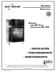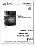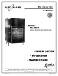
1
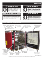
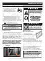
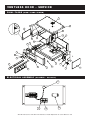
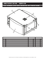
Rotisserie
Electric
Models:
AR-7E ROTISSERIE WITH
AR-7VH VENTLESS HOOD
• INSTALLATION
• OPERATION
• MAINTENANCE
W164 N9221 Water Street • P.O. Box 450 • Menomonee Falls, Wisconsin 53052-0450 USA
PHONE: 262.251.3800 • 800.558.8744 USA / CANADA
FAX: 262.251.7067 • 800.329.8744 U . S . A .
www.alto-shaam.com
PRINTED IN U.S.A.
ONLY
MN-28907 • 02/09
DELIVERY
U N PA C K I N G
This Alto-Shaam appliance has been
thoroughly tested and inspected to insure only the
highest quality unit is provided. Upon receipt,
check for any possible shipping damage and report
it at once to the delivering carrier. See
Transportation Damage and Claims section
located in this manual.
This appliance, complete with unattached
items and accessories, may have been delivered in
one or more packages. Check to ensure that all
standard items and options have been received
with each model as ordered.
Save all the information and instructions
packed with the appliance. Complete and return
the warranty card to the factory as soon as
possible to assure prompt service in the event of a
warranty parts and labor claim.
This manual must be read and understood by
all people using or installing the equipment
model. Contact the Alto-Shaam service
department if you have any questions concerning
installation, operation, or maintenance.
NOTE: All claims for warranty must include the
full model number and serial number of
the unit.
1. Carefully remove the
appliance from the
carton or crate.
NOTE: Do not discard the
carton and other
packaging material
until you have
inspected the unit
for hidden damage
and tested it for
proper operation.
®
®
2. Read all instructions in this manual carefully
before initiating the installation of this appliance.
DO NOT DISCARD THIS MANUAL.
This manual is considered to be part of the
appliance and is to be provided to the owner or
manager of the business or to the person
responsible for training operators. Additional
manuals are available from the Alto-Shaam
service department.
3. Remove all protective plastic film, packaging
materials, and accessories from the appliance
before connecting electrical power. Store any
accessories in a convenient place for future use.
A R -7E R oti s s eri e w i th A R -7VH Ventless Hood Operation & C are Manual • 1
SAFETY PROCEDURES
AND PRECAUTIONS
Knowledge of proper procedures is essential to the
safe operation of electrically and/or gas energized
equipment. In accordance with generally accepted
product safety labeling guidelines for potential
hazards, the following signal words and symbols
may be used throughout this manual.
DANGER
Used to indicate the presence of a
hazard that WILL cause severe
personal injury, death, or substantial
property damage if the warning
included with this symbol is ignored.
WA R N I N G
Used to indicate the presence of a
hazard that CAN cause personal injury,
possible death, or major property
damage if the warning included with
this symbol is ignored.
CAUTION
Used to indicate the presence of a
hazard that can or will cause minor or
moderate personal injury or property
damage if the warning included with
this symbol is ignored.
1. This appliance is intended to cook, hold or
process foods for the purpose of human
consumption. No other use for this appliance is
authorized or recommended.
2. This appliance is intended for use in commercial
establishments where all operators are familiar
with the purpose, limitations, and associated
hazards of this appliance. Operating
instructions and warnings must be read and
understood by all operators and users.
3. Any troubleshooting guides, component views,
and parts lists included in this manual are for
general reference only and are intended for use
by qualified technical personnel.
4. This manual should be considered a permanent
part of this appliance. This manual and all
supplied instructions, diagrams, schematics,
parts lists, notices, and labels must remain with
the appliance if the item is sold or moved to
another location.
NOTE
For equipment delivered for use
in any location regulated by the
following directive:
DO NOT DISPOSE OF ELECTRICAL
OR ELECTRONIC EQUIPMENT WITH
OTHER MUNICIPAL WASTE.
CAUTION
Used to indicate the presence of a hazard that can
or will cause minor personal injury, property
damage, or a potential unsafe practice if the
warning included with this symbol is ignored.
N O T E : Used to notify personnel of
installation, operation, or
maintenance information that is
important but not hazard related.
A R -7E R oti s s eri e w i th A R -7VH Ventl ess Hood Operation & Care Manual • 2
I N S TA L L AT I O N
DANGER
CAUTION
IMPROPER INSTALLATION,
ALTERATION, ADJUSTMENT,
SERVICE, OR MAINTENANCE COULD
RESULT IN SEVERE INJURY, DEATH
OR CAUSE PROPERTY DAMAGE.
READ THE INSTALLATION,
OPERATING AND MAINTENANCE
INSTRUCTIONS THOROUGHLY
BEFORE INSTALLING OR SERVICING
THIS EQUIPMENT.
CAUTION
METAL PARTS OF THIS EQUIPMENT
BECOME EXTREMELY HOT WHEN IN
OPERATION. TO AVOID BURNS,
ALWAYS USE HAND PROTECTION
WHEN OPERATING THIS APPLIANCE.
DANGER
DO NOT store or use gasoline or other
flammable vapors or liquids in the
vicinity of this or any other appliance.
TO PREVENT PERSONAL INJURY,
USE CAUTION WHEN MOVING OR
LEVELING THIS APPLIANCE.
S I T E I N S TA L L AT I O N
In order to maintain
established National
Sanitation Foundation
standards, all countermounted models must be
sealed to the counter with a
R.T.V. or silastic meeting
N.S.F. requirements or have
6" (152mm) unobstructed
clearance at the back and
sides of the unit.
®
1. The appliance must be installed on a
non-combustible, level surface.
2. DO NOT install this appliance in any area where it
may be affected by any adverse conditions such as
steam, grease, dripping water, high temperatures, or
any other severely adverse conditions.
3. For both safety and convenience, the rotisserie must
be installed in a location to provide easy access to the
controls and should be positioned at a safe and
convenient height to provide easy loading and
unloading of hot products.
4. This appliance must be kept free and clear of
any obstructions blocking access for maintenance
or service.
5. A rotisserie can be stacked with another rotisserie
oven or stacked on top of a matching holding
cabinet. Complete stacking instructions are
located in this manual.
A number of adjustments are associated with
initial installation and start-up. It is important
that these adjustments be conducted by a qualified
service technician. Installation and start-up
adjustments are the responsibility of the dealer or
user. These adjustments include but are not
limited to thermostat calibration, door adjustment,
leveling, electrical hook-up and installation of
optional casters or legs.
LEVELING
Level the appliance from side-to-side and
front-to-back with the use of a spirit level.
We recommend checking the level periodically to
make certain the floor has not shifted nor the
appliance moved.
NOTE: Failure to properly level this appliance
can cause improper function.
MINIMUM CLEARANCE REQUIREMENTS
A 6" (152mm) minimum clearance must be allowed at the
back and both sides of the unit. Warranty will become
null and void if these directions are not followed.
A R -7E R oti s s eri e w i th A R -7VH Ventless Hood Operation & C are Manual • 3
50-5/16"
(516mm)
SIDE VIEW
-
SOLID BACK
40-3/16" (1020mm)
38-3/16" (970mm)
38-1/16" (966mm)
37-1/8" (942mm)
25-7/16" (646mm)
Electrical Connection
at base of unit
50-5/16"
(516mm)
SIDE VIEW
-
SOLID BACK
32-7/16" (824mm)
FRONT VIEW
A R -7E R oti s s eri e w i th A R -7VH Ventl ess Hood Operation & Care Manual • 4
WITH PASS-THROUGH OPTION
PASS-THROUGH OPTION
Steam Vent
at top
88-3/4" (2255mm)
59-3/16" (1504mm) WITH
PASS-THROUGH OPTION
38-3/16" (970mm)
40-3/16" (1020mm)
4-3/8" (111mm)
CL
58-3/4" (1492mm) WITH SOLID BACK
57-1/16" (1449mm)
25-1/2" (649mm)
DOUBLE PANE CURVED GLASS DOOR
30-3/8" (722mm)
32" (813mm) WITH SOLID BACK
WITH PASS-THROUGH OPTION
32-7/16" (824mm)
WITH PASS-THROUGH OPTION
Steam Vent
at top
88-11-/16" (2252mm)
PASS-THROUGH OPTION
4-3/8" (111mm)
Electrical Connection
at base of unit
61-3/16" (1554mm) WITH PASS-THROUGH OPTION
WITH SOLID BACK
58-3/4" (1492mm)
57-1/16" (1449mm)
CL
35-13/16" (909mm)
38-7/8" (859mm)
WITH SOLID BACK
32-1/16" (814 mm)
30-3/8" (722mm)
25-1/2" (649mm)
AR-7E
38-3/16" (970mm)
40-3/16" (1020mm)
4-3/8" (111mm)
34-1/2" (876 mm)
WITH PASS-THROUGH OPTION
I N S TA L L AT I O N
S I T E I N S TA L L AT I O N
SINGLE PANE FLAT GLASS DOOR
25-7/16" (646mm)
I N S TA L L AT I O N
S I T E I N S TA L L AT I O N
AR-7VH
VENTLESS HOOD WITH FLAT DOOR
VENTLESS HOOD WITH CURVED DOOR
29-9/16" (750mm)
27-7/8" (707mm)
WITH SOLID BACK
WITH SOLID BACK
SIDE VIEW
SIDE VIEW
16"(404mm)
37-1/8" (942mm)
FRONT VIEW
A R -7E R oti s s eri e w i th A R -7VH Ventless Hood Operation & C are Manual • 5
87-7/16" (2221mm)
WITH SOLID BACK
WITH PASS-THROUGH OPTION
WITH PASS-THROUGH OPTION
56-1/2" (1434mm)
30-1/4" (767mm)
33-5/8" (853mm)
WITH PASS-THROUGH OPTION
58-13/16" (1494mm)
25-1/2" (646mm)
WITH SOLID BACK
30-1/4" (767mm)
27-7/8" (707mm)
WITH PASS-THROUGH OPTION
WITH PASS-THROUGH OPTION
88-7/16" (2246mm)
WITH SOLID BACK
WITH PASS-THROUGH OPTION
57" (1447mm)
61" (1549mm)
25-1/2" (646mm)
WITH SOLID BACK
33-5/8" (853mm)
WITH PASS-THROUGH OPTION
29-9/16" (750mm)
PASS-THROUGH OPTION
WITH PASS-THROUGH OPTION
PASS-THROUGH OPTION
I N S TA L L AT I O N
ELECTRICAL CONNECTION
The appliance must be installed by a qualified
service technician. The oven must be properly
grounded in accordance with the National
Electrical Code and applicable local codes.
DANGER
To avoid electrical shock, this
appliance MUST be adequately
grounded in accordance with local
electrical codes or, in the absence of
local codes, with the current edition
of the National Electrical Code
ANSI/NFPA No. 70. In Canada, all
electrical connections are to be
made in according with CSA C22.1,
Canadian Electrical Code Part 1 or
local codes.
Plug the unit into a properly grounded receptacle
ONLY, positioning the unit so that the plug is
easily accessible in case of an emergency. Arcing
will occur when connecting or disconnecting the
unit unless all controls are in the “ OFF ” position.
Proper receptacle or outlet configuration or
permanent wiring for this unit must be installed
by a licensed electrician in accordance with
applicable local electrical codes.
ELECTRICAL
VOLTAGE
208 ( AGCY )
230 ( AGCY )
240 ( AGCY )
208 ( AGCY )
230 ( AGCY )
240 ( AGCY )
380-415 ( AGCY )
380
415
PHASE
1
1
1
3
3
3
3
3
3
CYCLE / HZ
60
60
60
60
60
60
50/60
50/60
50/60
AMPS
40.0
42.0
38.0
33.0/ph
35.0/ph
32.0/ph
24.0/ph
22.0/ph
24.0/ph
KW
8.3
9.0
8.8
8.3
9.0
8.8
8.8
7.4
8.8
BARE END
NO PLUG
BARE END
NO PLUG
NO CORD
NO PLUG
DANGER
APPLIANCES WITH NO CORD
PROVIDED BY FACTORY MUST BE
EQUIPPED WITH A CORD OF
SUFFICIENT LENGTH TO PERMIT
THE APPLIANCE TO BE MOVED
FOR CLEANING.
ELECTRICAL CONNECTIONS MUST
BE MADE BY A QUALIFIED SERVICE
TECHNICIAN IN ACCORDANCE WITH
APPLICABLE ELECTRICAL CODES.
“WA RNING” RISK OF FIR E!
Use a UL Listed grounding type plug rated 250 Volts, 50
Amperes, 1 Phase, 3 wire for single phase units and 250 V,
50 A, 3 Phase, 4 wire for three phase units. Plug to be
selected and installed only by qualified service personnel.
Individual conductors are marked L 1 , L 2 , L 3 when
applicable, N when applicable, and G.
THE ROTISSERIE CAN BE HARD WIRED. PERMANENT
WIRING FOR ALL OVENS MUST BE INSTALLED BY A
LICENSED ELECTRICIAN IN ACCORDANCE WITH
APPLICABLE, LOCAL ELECTRICAL CODES.
230V ROTISSERIES FOR HARD WIRING MUST BE
EQUIPPED WITH AN EXTERNAL MAIN SWITCH
WHICH DISCONNECTS ALL POLES WITH A CONTACT
SEPARATION OF AT LEAST 3MM FOR ALL POLES.
After wiring and power connection has been
completed, turn the main power switch to the “ ON ”
position. The main power switch can be left “ ON ”
for daily use, but should be turned “ OFF ” when
cleaning or performing maintenance or repairs to
the rotisserie.
REGARDING INTERNATIONAL
STANDARD UNITS:
If the unit is not equipped with flexible cord
with plug, an all-pole country approved
disconnection device which has a contact
separation of at least 3mm in all poles must be
incorporated in the fixed wiring for disconnection.
When using a cord without a plug, the
green/yellow conductor shall be connected to the
terminal which is marked with the ground symbol.
If a plug is used, the socket outlet must be easily
accessible. If the power cord needs replacement,
use a similar one obtained from the distributor.
For 230V units: To prevent an electrical shock
hazard between the appliance and other
appliances or metal parts in close vicinity, an
equalization-bonding stud is provided. An
equalization bonding lead must be connected to
this stud and the other appliances / metal parts to
provide sufficient protection against potential
difference. The terminal is marked with the
following symbol.
DANGER
ENSURE POWER SOURCE
MATCHES VOLTAGE STAMPED
ON APPLIANCE NAMEPLATE.
A R -7E R oti s s eri e w i th A R -7VH Ventl ess Hood Operation & Care Manual • 6
I N S TA L L AT I O N
D R I P T R AY I N S TA L L AT I O N
Attach tray using two carriage bolts in base panel. Lift tray up and away to remove.
S TA C K I N G C O M B I N AT I O N S & I N S TA L L AT I O N R E Q U I R E M E N T S
AR-7VH ventless hood over AR-7E rotisserie
S TA CKIN G C O MBIN ATIO N S ( FACTORY
INSTALLED )
Requires 4" (102mm) legs for counter top applications. Free standing floor installations
require 6" (152mm) leg assembly 5001414 or 5" (127mm) casters 4007.
[ OVERALL
HEIGHT :
54-7/16" (1384mm)]
AR-7VH ventless hood over AR-7E rotisserie over AR-7H companion holding cabinet
Requires 6" (152mm) legs with flanged feet 5001761 bolted to the floor.
[ OVERALL
HEIGHT :
90-13/16" (2307mm)]
CAUTION
STACKING APPLICATIONS
OUTSIDE THE U.S. REQUIRE
FLANGED FEET AND MUST
BE BOLTED TO THE FLOOR.
CAUTION
MAKE CERTAIN TO FASTEN
EACH OF THE FOUR HOLES
A R -7E R oti s s eri e w i th A R -7VH Ventless Hood Operation & C are Manual • 7
I N S TA L L AT I O N
S TA C K I N G I N S T R U C T I O N S
A rotisserie with ventless hood can be stacked on top of a
matching holding cabinet.
Only screws, lock washers, and hex nut are required to fasten
units together when stacking a rotisserie on top of a matching
holding cabinet.
All fastening holes have been prepunched. The stacking
combination also requires the minimum clearance of 6-inches
(152mm) at the top, back and both sides.
1. Remove the access panels of both units.
2. Punch out the knock out hole (A) in the top panel of the lower unit.
7
3. Remove power cord from upper unit and discard.
4. The new power cord and strain relief bushing for upper unit
should be routed through the knock out hold in the top panel
of the lower unit.
8
5. Carefully lift and place the upper unit into position aligning on
bottom unit.
A
8
6. Secure units together by inserting a hex head screw and washer
inside upper unit, and back them with a washer, lock-washer,
and nut inside lower unit. Securely tighten all four screws.
7. Attach a strain relief bushing to the bottom panel of the lower
unit to the left of the existing power cord. (B)
8. Route power cord from upper unit through the strain relief
bushings, then tighten bushings.
10
5
3
9. Replace the access panels on both units.
B
1
9
2
11
10. Attach 4: Support Brackets (1010092) and any required feet or
casters (varies) with 4: SC-2191, 4: WS-2867, and 4: WS-22095.
6
AR-7EVH OVER AR-7H STACKING ASSEMBLY
ITEM
NO.
PART
NO.
1
1010092
2
PART DESCRIPTION
QTY
BRACKET, SUPPORT, BASE
4
BU-33948
BUSHING, STRAIN RELIEF, 18MM-25MM AR-7E
1
3
CD-3987
CORD, 8/4 SEEO W-A, 105C, (-50C)
1
4
CR-3801*
CONNECTORS, *CT, RING, 10MM, SQ/M6
4
5
NU-2437
NUT, 1/4-20 HEX S/S
4
6
SC-2191
SCREW, HEX HEAD, 5/16-18 X 1" LONG
16
7
SC-27385
SCREW, 1/4/20 X 3/4" LG HEX HEAD
4
8
WS-22094
WASHER, 1/4", FLAT, 5/8 OD 18-8 SS
8
9
WS-22095
WASHER, 3/8" ID, 1" OD, FLAT, 18-8 SS
16
10
WS-2294
LOCK WASHER, 1/4"
4
11
WS-2867
LOCK WASHER, 5/16"
16
*NOT SHOWN
A R -7E R oti s s eri e w i th A R -7VH Ventl ess Hood Operation & Care Manual • 8
I N S TA L L AT I O N
AR-7E & AR-7VH — OPTIONS & ACCESSORIES
DE S CR IPT ION
PART NUM BER
DOOR OPTIONS
SINGLE PANE FLAT GLASS WITH HANDLE
5007012
SINGLE PANE FLAT GLASS WITHOUT HANDLE
5007013
ON NON - CONTROL SIDE
DOOR HANDLE
DRIP PAN,
1001976
STAINLESS STEEL
DRIP PAN TRAY,
FLAT GLASS DOOR
5004859
CURVED GLASS DOOR
1002598
DOOR MOUNTED
FEET, RUBBER, 2" (51mm)
CE ONLY
FOR COUNTER TOP UNITS ONLY
5001765
ASSEMBLY,
6" (152mm)
5001414
ASSEMBLY, FLANGED FEET,
6" (152mm)
( REQUIRED
FOR STACKING UNITS )
MULTI-PURPOSE WIRE BASKET (.50 diameter pin)
( FACTORY
INSTALLED )
STANDS
5001761
BS-26019
ANGLED SPIT, STAINLESS STEEL
STACKING ASSEMBLY
5001614
4" ( 102mm)
ASSEMBLY,
LEGS
SPITS
HD-26900
SI-25934
PIERCING SPIT, STAINLESS STEEL
SI-25729
TURKEY SPIT, STAINLESS STEEL
SI-26980
ANGLED SPIT, TEFLON COATED
5001335
AR-7E
AR-7E
OVER
OVER
AR-7E
AR-7E
AR-7E
AR-7H (208-240V, 1PH)
AR-7H (208-240V, 3PH)
OVER
AR-7H (380-415V)
5008948
5008922
36" (914mm)
FR-26550
750-S, 36" (914mm)
5002058
W / SHELF,
OVER
5008787
TEFLON® COATED ACCESSORY PACKAGE
5001302
COMMERCIAL GRADE , INCLUDES DISKS , DRIP TRAY AND
VENTLESS HOOD REPLACEMENT FILTERS
7
ANGLED SPITS
GREASE FILTER
FI-25867
CHARCOAL FILTER
FI-25866
A R -7E R oti s s eri e w i th A R -7VH Ventless Hood Operation & C are Manual • 9
O P E R AT I N G I N S T R U C T I O N S
CONTROL
IDENTIFICATION
Cook Cycle Indicator Bar
Holding Indicator Bar
Product Ready Indicator Bar
Preheat Indicator Bar
Cook Time Indicator Bar 1
Cook Time Indicator Bar 2
and
UP Arrow Key
LED Display
DOWN Arrow Key
➥ FOR 2-STEP COOKING TIME
Cook Temperature Indicator Bar 1
Cook Temperature Indicator Bar 2
Preset Key Lock Indicator Bar
➥ FOR 2-STEP COOKING
Hold Key
ON/OFF Power Key
Time Key
Cook Key
Start Key
Indicator Light
Preset Menu
Program Keys
OPTION
Underscore Light
Program Menu
Identification Card Slot
Preset Program Cancellation Key
Stop Key
Cool Down
Jog Key
TO ROTATE SPITS IN INCREMENTS
FOR PRODUCT REMOVAL
WHEN DOOR IS OPEN
A R -7E R oti s s eri e w i th A R -7VH Ventless Hood Operation & Care Manual • 10
O P E R AT I N G I N S T R U C T I O N S
Press the
The
ON / OFF
ON / OFF
key.
indicator light will illuminate.
The display will show the last set holding temperature.
The hold indicator will illuminate.
The rotisserie will begin to preheat to the holding temperature shown in the display.
Press the COOK key.
The COOK and the TIME underscore lights will alternately illuminate.
The display will indicate the last set cooking temperature when the COOK underscore light is illuminated.
The display will indicate the last set cooking time when the TIME underscore light is illuminated.
Cook temperature indicator bar will illuminate for:
COOK TEMPERATURE 1
AFTER PRESSING THE COOK KEY:
…to change the displayed
temperature, press the up and
Press the COOK key again if 2-step cooking is required.
Cook temperature indicator bar will illuminate for:
COOK TEMPERATURE 2
down arrow key when …
COOK TEMPERATURE 1
or
COOK TEMPERATURE 2
is illuminated.
Press the TIME key.
The TIME underscore light will illuminate.
The display will indicate the last set cooking time when the TIME underscore light is illuminated.
The display will indicate the last set cooking temperature when the COOK underscore light is illuminated.
Time indicator bar will illuminate for:
TIME 1
Press the TIME key again if 2-step cooking is required.
Time indicator bar will illuminate for:
TIME 2
Press the HOLD key.
The HOLD underscore light will illuminate.
The display will indicate the last set holding temperature.
• Product programming can be considered complete after the holding
temperature has been set or additional browning
time can be added if desired.
AFTER PRESSING THE TIME KEY:
…to change the displayed time,
press the up and down arrow
key when …
TIME 1
or
TIME 2
is illuminated.
AFTER PRESSING THE HOLD KEY:
Change the holding temperature,
by pressing the up and down
arrow key when the HOLD
underscore light is illuminated.
• Automatic holding time will activate when the cooking cycle time
ready BAR is illuminated.
and any additional browning time has elapsed and the PRODUCT READY
• The product will continue to cook as it decreases from the cooking temperature to the
holding temperature.For best results, always allow for product temperature override.
A R -7E R oti ss eri e w i th A R -7VH Ventless Hood Operation & Care Manual • 11
O P E R AT I N G I N S T R U C T I O N S
A D D I T I O N A L B R O W N I N G F E AT U R E
The control allows the operator to set a specific period of time for additional browning between the end of the
ready BAR at the end of the cooking cycle. Browning
COOK TIME and the illumination of the PRODUCT READY
time is to be added during initial product programming.
AFTER THE HOLDING TEMPERATURE HAS BEEN SET,
PRESS THE HOLD KEY AGAIN FOR BROWNING TIME DISPLAY.
The display will indicate “0” time or the last browning time.
To change browning time, press the up and down arrow key
when “0” time appears in the display. Note: To disable the
browning feature set the time to “0:00”
AVERAGE BROWNING TIME FOR MOST PRODUCTS IS BETWEEN 5 AND 20 MINUTES
• The radiant heat browning feature will only operate if a time period has been set.
• The product will continue to cook as it decreases from the cooking temperature to the holding temperature.
For best results, always allow for product temperature override.
ready BAR will illuminate at the end of the set browning time and the oven temperature
• The PRODUCT READY
will decrease to the set holding temperature in the automatic hold mode.
THE ROTISSERIE WILL CONTINUE TO PREHEAT UNTIL THE COOK TEMPERATURE IS REACHED.
A L WAY S A L L O W T H E R O T I S S E R I E T O P R E H E AT
T O T H E F U L L S E T C O O K I N G T E M P E R AT U R E
ready BAR
When fully preheated, the START key and the PRODUCT READY
will flash and the control will beep four times
LOAD PRODUCT
PRESS START
• The spit motor will begin to rotate.
• The display will alternate between showing the set cook temperature and set cook time.
ready BAR will
When the cooking time and any additional set browning time is complete, the PRODUCT READY
illuminate to indicate the end of the cooking function.
A U T O M AT I C
H O L D I N G T I M E W I L L A C T I VAT E . • The rotisserie will remain at the set holding temperature up to a period of four (4) hours.
• The display will alternate between the set holding temperature and the elapsed holding time since READY.
• The rotisserie will shut down after the 4-hour automatic holding time period has elapsed.
A R -7E R oti s s eri e w i th A R -7VH Ventless Hood Operation & Care Manual • 12
O P E R AT I N G I N S T R U C T I O N S
PRESET MENU KEY OPTION
The Alto-Shaam rotisserie provides the operator with the ability to set as many as seven cooking programs.
Each cooking program can be preset to include all cooking and holding functions. Cooking programs are
stored and recalled using the P RESET Keys labeled 1 thr ough 7.
PROGRAMMING A COOKING PROGRAM:
With the rotisserie oven in the “ OFF ” position, determine the food product procedure to be
programmed. Press and release control ON / OFF key. The oven will beep for one second and power to
the unit will be indicated by an illuminated green indicator light located in the upper left corner of the
O N /O FF key. The oven will begin operating in the hold mode. The amber hold indicator will be
illuminated and the last set hold temperature will be displayed.
E N T E R A L L C O O K I N G A N D H O L D I N G PA R A M E T E R S F O R T H E
P R O D U C T S E L E C T E D A S I N S T R U C T E D O N T H E P R E V I O U S PA G E .
Select a number for the programmed product. Press and hold the selected P RESET number key
until you hear an audible signal which will occur within approximately 4 seconds. The number
key program indicator light will illuminate. The programmed product is now stored in memory
on the specific number key selected. Additional programs can be stored in the remaining P RESET
Keys if not previously programmed.
NOTE: The last P RESET Key programmed will be the oven cooking run sequence for the next product to
be programmed. Settings can be manually changed for the next product and an alternate
pre-programmed letter key selected.
TO COOK WITH PRESET MENU KEYS:
PRESS AND RELEASE CONTROL ON / OFF KEY.
• The control will beep and the green indicator light on the ON / OFF key will illuminate.
• The amber hold indicator will illuminate.
• The oven will begin operating in the hold mode.
• The previously set hold temperature will be displayed.
• The green indicator will illuminate on all programmed PRESET Keys.
PRESS DESIRED PRESET KEY (1 THROUGH 7)
• The Pre-Heat indicator will illuminate.
➥ The rotisserie oven will automatically preheat to the cooking temperature programmed.
• The oven will beep when preheated and the preheat indicator will go out.
• Both the Ready and Start indicator lights will flash.
➥ The set cook temperature will be maintained by the oven and appear in the display
while in the ready/start mode.
LOAD THE PREPARED PRODUCT SPITS INSIDE OVEN AND CLOSE THE OVEN DOOR.
PRESS AND RELEASE
START KEY.
NOTE: The rotisserie will beep 4 times when cooking is finished.
A R -7E R oti s s eri e w i th A R -7VH Ventless Hood Operation & Care Manual • 13
O P E R AT I N G I N S T R U C T I O N S
CHICKEN, WHOLE
ATTENTION
CHICKEN ,
After programming a specific product into memory on a
preset key number, it is suggested the product be
identified by inserting a label in the Program Menu
Identification Card Slot.
QUARTERS
TURKEY BREAST
PORK RIBS
PORK LOIN
LAMB LEGS
TO ERASE A PRESET
To erase a preset, the oven must be in either the power-up hold mode or in the preheat mode. The oven
cannot be in a cook or automatic hold.
When the oven is in the power-up hold mode or in the preheat mode, press and hold both the C ANCEL Key
and the appropriate number P RESET Key to be erased. The oven will beep for seven (7) seconds and the
preset indicator light will go out once the preset is erased.
PRESET MENU LOCK AND UNLOCK
The preset menu keys can be locked at any time in order to prevent inadvertent or accidental setting changes.
To lock the preset keys, press the UP A RROW Key along with the O N / O F F Key. The
rotisserie will beep and the preset lock indicator will illuminate. Release all keys. The
rotisserie presets are now locked.
To unlock the preset keys, press the DOWN A RROW Key along with along with the O N / O F F Key. The rotisserie
will beep twice and the preset lock indicator will extinguish. Release all keys. The preset keys are now
unlocked and ready for programming.
FA H RENHEIT OR CELSIUS SELECTIO N
With the control O F F , P R E S S A N D H O L D the UP arrow key
for 2 seconds to toggle the temperature scale. When toggled,
the new temperature scale will appear on the display.
CO O L DOWN
To cool down the unit:
• Press the Stop button
•
P R E S S A N D H O L D the Cool Down
key until “cool” appears in the
display. The unit will run the fan
only with or with out the door
open to cool down the cavity.
• Press the Stop button again to
cancel the cool down process.
WA R N I N G
THE CONVECTION FAN CONTINUES
TO ROTATE DURING THE COOL DOWN
PROCESS. DO NOT OPEN THE PANEL
WHILE COOLING DOWN THE
ROTISSERIE OVEN.
A R -7E R oti s s eri e w i th A R -7VH Ventless Hood Operation & Care Manual • 14
O P E R AT I N G I N S T R U C T I O N S
PRODUCT LOADING
STANDARD SPITS
Each of the seven rotisserie spits includes two
welded prongs on the square end and one
welded, ridged prong on the tapered end. Insert
the two-prong, square end into the two holes
indicated on the disk assembly drive wheel in the
drawing. Insert the tapered, ridged-prong end
into the top hole indicated on the opposite side
and maneuver until the ridge catches in the hole.
B
OPTIONAL SPITS/BASKETS
When optional spits are used, insert the spits
in the drive wheel as indicated in the illustration.
When inserting the basket, put the smooth pin
(A) end in first. When removing the basket, the
machined pin (B) comes out first.
IMPORTANT NOTE:
When using a partial quantity of standard or
optional spits, space the spits evenly as possible
around the drive wheel to maintain balance and
even rotation.
S P E C I A L AT T E N T I O N :
A combination of standard, piercing, and
basket spits can be used at the same time but NOT
in every spit insertion position. The use of a spit
in every position will inter fere with the free
rotation of the baskets. Using a combination of
spits can only be accomplished at significantly
reduced rotisserie capacity.
A R -7E R oti s s eri e w i th A R -7VH Ventless Hood Operation & Care Manual • 15
A
O P E R AT I N G I N S T R U C T I O N S
PRODUCT LOADING
STANDARD SPIT
Insert whole chickens with the legs toward the square end of the spit. Load up to 3, 3-1/2 lb (1,6 kg)
chickens per spit for a total of 21 chickens or 4, 2-1/2 lb (1,1 kg) chickens for a total of 28 whole chickens.
PIERCING SPIT ( OPTION )
The optional piercing spit (Item SI-25729) will accommodate 4, 2-1/2 lb (1,1 kg) to 3-1/2 lb (1,6 kg) whole
chickens per spit.
BASKET SPIT ( OPTION )
Basket spits (Item BS-26019 with .50 diameter pin) are useful for irregular size products, denser items, or
heavier products that need more support than the piercing spits.
TURKEY SPIT ( OPTION )
The optional turkey spit (Item SI-26980)
will accommodate a turkey up to 25 lb.
A R -7E R oti s s eri e w i th A R -7VH Ventless Hood Operation & Care Manual • 16
O
OP
PE
ER
R AT
AT II N
NG
G II N
NS
ST
TR
RU
UC
CT
T II O
ON
NS
S
CHICKEN, HALVES OR PIECES (8- PIECE
CAPACITY:
CUT )
2-1/2 to 3 lb (1,1 to 1,4 kg)
SUGGESTED SPIT :
BASKET
REMOVE PRODUCT IMMEDIATELY
WHEN INTERNAL TEMPERATURE IS REACHED
USE THE FOLLOWING DIRECTIONS WHEN
LONG-TERM HOLDING IN THE ROTISSERIE
LOAD PRODUCT WHEN OVEN BEEPS AT REGULAR INTERVALS AND
THE START KEY AND READY INDICATOR BEGIN FLASHING
LOAD PRODUCT WHEN OVEN BEEPS AT REGULAR INTERVALS AND
THE START KEY AND READY INDICATOR BEGIN FLASHING
ALLO W THE ROTI SSERIE TO PREHEAT
Press the
ON / OFF
ALLOW THE ROT IS S ERIE TO PREHEAT
Press the
key.
ON / OFF
key.
Press and set the COOK key.
COOK TEMPERATURE 1
Press and set the COOK key.
COOK TEMPERATURE 1
425°F (218°C)
425°F (218°C)
Press and set the COOK key for 2-step cooking.
Press and set the COOK key for 2-step cooking.
COOK TEMPERATURE 2
COOK TEMPERATURE 2
NOT REQUIRED
NOT REQUIRED
Press and set the TIME key.
TIME 1
Press and set the TIME key.
TIME 1
20 MINUTES
30 MINUTES
Press and set the TIME key
for 2-step cooking.
TIME 2
Press and set the TIME key
for 2-step cooking.
TIME 2
NOT REQUIRED
NOT REQUIRED
Press and set the HOLD key.
Press and set the HOLD key.
160°F (71°C)
160°F (71°C)
Press the HOLD key again
to add BROWNING TIME.
Press the HOLD key again
to add BROWNING TIME.
NOT REQUIRED
NOT REQUIRED
WHEN PREHEATED:
LOAD PRODUCT
PRESS START
FINAL INTERNAL TEMPERATURE
185°F (85°C)
ready
WHEN PREHEATED:
LOAD PRODUCT
PRESS START
FINAL INTERNAL TEMPERATURE
185°F (85°C)
A R -7E R oti s s eri e w i th A R -7VH Ventless Hood Operation & Care Manual • 17
ready
O P E R AT I N G I N S T R U C T I O N S
CHICKEN, WHOLE
CAPACITY:
2-1/2 to 3 lb (1,1 to 1,4 kg)
SUGGESTED SPIT :
STANDARD OR PIERCING SPIT
REMOVE PRODUCT IMMEDIATELY
WHEN INTERNAL TEMPERATURE IS REACHED
USE THE FOLLOWING DIRECTIONS WHEN
LONG-TERM HOLDING IN THE ROTISSERIE
LOAD PRODUCT WHEN OVEN BEEPS AT REGULAR INTERVALS AND
THE START KEY AND READY INDICATOR BEGIN FLASHING
LOAD PRODUCT WHEN OVEN BEEPS AT REGULAR INTERVALS AND
THE START KEY AND READY INDICATOR BEGIN FLASHING
ALLOW THE ROTIS SERIE TO PREHEAT
Press the
ON / OFF
key.
AL LOW THE ROT IS SERIE TO PREHEAT
Press the
Press and set the COOK key.
COOK TEMPERATURE 1
ON / OFF
key.
Press and set the COOK key.
COOK TEMPERATURE 1
400°F (204°C)
375°F (190°C)
Press and set the COOK key for 2-step cooking.
COOK TEMPERATURE 2
Press and set the COOK key for 2-step cooking.
COOK TEMPERATURE 2
425°F (218°C)
425°F (218°C)
Press and set the TIME key.
TIME 1
Press and set the TIME key.
TIME 1
35 MINUTES
20 MINUTES
Press and set the TIME key
for 2-step cooking.
TIME 2
Press and set the TIME key
for 2-step cooking.
TIME 2
15 MINUTES
20 MINUTES
Press and set the HOLD key.
Press and set the HOLD key.
160°F (71°C)
160°F (71°C)
Press the HOLD key again
to add BROWNING TIME.
Press the HOLD key again
to add BROWNING TIME.
5 MINUTES
5 MINUTES
WHEN PREHEATED:
LOAD PRODUCT
PRESS START
WHEN PREHEATED:
LOAD PRODUCT
PRESS START
FINAL INTERNAL TEMPERATURE
FINAL INTERNAL TEMPERATURE
185°F (85°C)
185°F (85°C)
ready
A R -7E R oti s s eri e w i th A R -7VH Ventless Hood Operation & Care Manual • 18
O P E R AT I N G I N S T R U C T I O N S
TURKEY BREAST
PORK RIBS
CAPACITY:
CAPACITY:
5-1/2 lb (2,5 kg)
TOTAL: 8 TURKEY BREASTS
SUGGESTED SPIT :
SUGGESTED SPIT :
BASKET
AL LOW THE ROTISSERIE TO PREHEAT
LOAD PRODUCT WHEN OVEN BEEPS AT REGULAR INTERVALS AND
THE START KEY AND READY INDICATOR BEGIN FLASHING
Press the
ON / OFF
2-3/4 DOWN
TOTAL: 2 FULL
key.
BASKET
AL LOW THE ROT IS SERIE TO PREHEAT
LOAD PRODUCT WHEN OVEN BEEPS AT REGULAR INTERVALS AND
THE START KEY AND READY INDICATOR BEGIN FLASHING
Press the
Press and set the COOK key.
COOK TEMPERATURE 1
SLABS PER BASKET
ON / OFF
key.
Press and set the COOK key.
COOK TEMPERATURE 1
250°F (121°C)
250°F (121°C)
Press and set the COOK key for 2-step cooking.
COOK TEMPERATURE 2
Press and set the COOK key for 2-step cooking.
COOK TEMPERATURE 2
400°F (204°C)
375°F (191°C)
Press and set the TIME key.
TIME 1
Press and set the TIME key.
TIME 1
1-1/2 HOURS
40 MINUTES
Press and set the TIME key
for 2-step cooking.
TIME 2
Press and set the TIME key
for 2-step cooking.
TIME 2
15 MINUTES
5 MINUTES
Press and set the HOLD key.
Press and set the HOLD key.
165°F (74°C)
150°F (66°C)
Press the HOLD key again
to add BROWNING TIME.
Press the HOLD key again
to add BROWNING TIME.
NONE:
WHEN PREHEATED:
LOAD PRODUCT
15 MINUTES
NOT REQUIRED
PRESS START
WHEN PREHEATED:
LOAD PRODUCT
PRESS START
FINAL INTERNAL TEMPERATURE
FINAL INTERNAL TEMPERATURE
180°F (82°C)
160° TO 170°F (71° TO 77°C)
ready
A R -7E R oti s s eri e w i th A R -7VH Ventless Hood Operation & Care Manual • 19
ready
O P E R AT I N G I N S T R U C T I O N S
PORK LOIN, BONELESS
LAMB LEG, BONELESS
CAPACITY:
CAPACITY:
5 to 7 lb (2,3 to 3,2 kg) AVERAGE WEIGHT
TOTAL: 1 TO 2 PORK LOINS PER BASKET
SUGGESTED SPIT :
SUGGESTED SPIT :
BASKET
ALLOW THE ROTIS SERIE TO PREHEAT
LOAD PRODUCT WHEN OVEN BEEPS AT REGULAR INTERVALS AND
THE START KEY AND READY INDICATOR BEGIN FLASHING
Press the
ON / OFF
key.
ALLOW THE ROT IS S ERIE TO PREHEAT
ON / OFF
key.
Press and set the COOK key.
COOK TEMPERATURE 1
250°F (121°C)
250°F (121°C)
Press and set the COOK key for 2-step cooking.
COOK TEMPERATURE 2
Press and set the COOK key for 2-step cooking.
COOK TEMPERATURE 2
350°F (177°C)
350°F (177°C)
Press and set the TIME key.
TIME 1
Press and set the TIME key.
TIME 1
1 HOUR
1-1/2 HOURS
Press and set the TIME key
for 2-step cooking.
TIME 2
Press and set the TIME key
for 2-step cooking.
TIME 2
15 MINUTES
15 MINUTES
Press and set the HOLD key.
Press and set the HOLD key.
160°F (71°C)
150°F (66°C)
Press the HOLD key again
to add BROWNING TIME.
WHEN PREHEATED:
LOAD PRODUCT
PIERCING
LOAD PRODUCT WHEN OVEN BEEPS AT REGULAR INTERVALS AND
THE START KEY AND READY INDICATOR BEGIN FLASHING
Press the
Press and set the COOK key.
COOK TEMPERATURE 1
NONE:
8 to 11 lb (4 to 5 kg)
TOTAL: 60 lb (27 kg) maximum
MEDIUM DONENESS
Press the HOLD key again
to add BROWNING TIME.
15 MINUTES
NOT REQUIRED
PRESS START
WHEN PREHEATED:
LOAD PRODUCT
PRESS START
FINAL INTERNAL TEMPERATURE
FINAL INTERNAL TEMPERATURE
155° to 165°F (68° to 74°C)
145° TO 150°F (63° TO 66°C)
ready
A R -7E R oti s s eri e w i th A R -7VH Ventless Hood Operation & Care Manual • 20
ready
CARE AND CLEANING
CLEANING AND PREVENTIVE MAINTENANCE
PROTECTING STAINLESS STEEL SURFACES
It is important to guard against
corrosion in the care of
stainless steel surfaces.
Harsh, corrosive, or
inappropriate chemicals can
completely destroy the
protective surface layer of stainless steel.
Abrasive pads, steel wool, or metal implements
will abrade surfaces causing damage to this
protective coating and will eventually result in
areas of corrosion. Even water, particularly hard
water that contains high to moderate
concentrations of chloride, will cause oxidation
and pitting that result in rust and corrosion. In
addition, many acidic foods spilled and left to
remain on metal surfaces are contributing factors
that will corrode surfaces.
Proper cleaning agents, materials, and
methods are vital to maintaining the appearance
and life of this appliance. Spilled foods should be
removed and the area wiped as soon as possible
but at the very least, a minimum of once a day.
Always thoroughly rinse surfaces after using a
cleaning agent and wipe standing water as quickly
as possible after rinsing.
CLEANING AGENTS
Use non-abrasive cleaning products designed for
use on stainless steel surfaces. Cleaning agents
must be chloride-free compounds and must not
contain quaternary salts. Never use hydrochloric
acid (muriatic acid) on stainless steel surfaces.
Always use the proper cleaning agent at the
manufacturer's recommended strength.
Contact your local cleaning supplier for
product recommendations.
CLEANING MATERIALS
The cleaning function can usually be accomplished
with the proper cleaning agent and a soft, clean
cloth. When more aggressive methods must be
employed, use a non-abrasive scouring pad on
difficult areas and make certain to scrub with the
visible grain of surface metal to avoid surface
scratches. Never use wire brushes, metal scouring
pads, or scrapers to remove food residue.
BRU
S
IRE
EL PA
STE
DS
NO
W
S
HE
NO
SCR APE R
O
S
N
CAUTION
TO PROTECT STAINLESS STEEL
SURFACES, COMPLETELY AVOID
THE USE OF ABRASIVE CLEANING
COMPOUNDS, CHLORIDE BASED
CLEANERS, OR CLEANERS
CONTAINING QUATERNARY SALTS.
NEVER USE HYDROCHLORIC ACID
(MURIATIC ACID) ON STAINLESS
STEEL. NEVER USE WIRE
BRUSHES, METAL SCOURING
PADS OR SCRAPERS.
A R -7E R oti s s eri e w i th A R -7VH Ventless Hood Operation & Care Manual • 21
CARE AND CLEANING
EQUIPMENT CARE
Under normal circumstances, this oven should provide you with long and trouble free service.
There is no preventative maintenance required, however, the following Equipment Care Guide
will maximize the potential life and trouble free operation of this oven. The cleanliness and
appearance of this equipment will contribute considerably to operating efficiency and savory,
appetizing food. Good equipment that is kept clean works better and lasts longer.
DANGER
DISCONNECT UNIT FROM
POWER SOURCE BEFORE
CLEANING OR SERVICING.
CLEAN DAILY
CAUTION
METAL PARTS OF THIS EQUIPMENT
BECOME EXTREMELY HOT WHEN IN
OPERATION. TO AVOID BURNS,
ALWAYS USE HAND PROTECTION
WHEN OPERATING THIS APPLIANCE.
DISK DRIVE
1. Press the electrical power switch to the
" OFF " position.
2. Allow rotisserie surfaces to cool.
3. Disconnect the rotisserie from the electrical
power source.
4. Remove all detachable items such as spits and
grease deflection trays. Drain grease from the
drip pan and remove the drip pan from the oven
when draining is complete.
5. Remove rotisserie drive assembly from the
interior of the oven.
a. Supporting the central drive tube assembly,
slide the metal washer and the collar on
both sides of the drive tube toward the
center of the tube to disengage.
b. Remove the disk drive wheels by pulling
each directly toward the center of the oven
compartment.
6. Wash all detached items separately in a ware
washing area or sink. Do not use abrasive or
corrosive cleaners. Only hot, soapy water is
required for the optional Teflon ® coated items.
7. Wipe the interior metal surfaces of the oven with
a paper towel to remove loose food debris.
8. Clean interior with a damp cloth or sponge and
any good commercial detergent at the
recommended strength.
9. Spray heavily soiled areas with a water soluble
degreaser and let stand for 10 minutes.
After 10 minutes, remove soil with a plastic
scouring pad.
10. Rinse surfaces thoroughly by wiping with sponge
and clean, warm water
11. Remove excess water with sponge and wipe dry
with a clean cloth or air dry. Leave door open
until interior is completely dry. Always replace
all removable parts including drip pan and grease
deflection trays before operating.
WASHER
COLLAR
DRIVE TUBE
ASSEMBLY
12. Interior can be wiped with a sanitizing solution
after cleaning and rinsing. This solution must
be approved for use on stainless steel food
contact surfaces.
13. Wipe control panel and door handle(s) thoroughly
since these areas harbor food debris and bacteria.
Dry the control panel dry with a clean, soft cloth.
14. To help maintain the protective film coating on
polished stainless steel, clean the exterior of the
cabinet with a cleaner recommended for stainless
steel surfaces. Spray the cleaning agent on a
clean cloth and wipe with the grain of the
stainless steel. For optional color coated exterior
surfaces, wipe with a damp cloth or sponge and
wipe dry with a clean cloth.
15. Clean glass doors with a standard, commercial
glass cleaner.
CAUTION
Always follow appropriate state
or local health (hygiene) regulations
regarding all applicable cleaning
and sanitation requirements
for equipment.
A R -7E R oti s s eri e w i th A R -7VH Ventless Hood Operation & Care Manual • 22
CARE AND CLEANING
D A I LY G A S K E T C L E A N I N G
It is important to prolong the life of the oven gasket by
cleaning this item on a daily basis. The acids and
related compounds found in fat, particularly chicken fat,
will weaken the composition of the gasket unless
cleaned on a daily basis.
Routine cleaning will help protect the composition of
the gasket from deterioration caused by acidic foods.
After allowing the oven to cool, remove pull-out gasket
and wash in hot, soapy water. Do not place gasket in
the dishwasher
CAUTION
DANGER
ALWAYS REPLACE THE DOOR
GASKET BEFORE CLEANING
THE INTERIOR OR OPERATING
THE APPLIANCE.
DISCONNECT UNIT FROM
POWER SOURCE BEFORE
CLEANING OR SERVICING.
CLEAN CONVECTION BOX
Remove the screws holding the convection fan panel unto the
inside of the cooking chamber. Using a commercial degreaser
spray the back and front and allow the degreaser to soften the
grease for 10 minutes. Using a plastic scouring pad, scrub any
hard deposits and rinse with hot water.
SCREWS
Using a damp sponge and a plastic scouring pad if needed,
wipe out any grease deposits that may be built up on the area
surrounding the convection element and fan blade, taking care
not to bend the element or the blade. A degreaser may be
sprayed in this area to help dissolve any grease deposits that
may be built up, but only a damp cloth or sponge can be used
to remove the dissolved grease.
Reinstall fan panel and tighten screws finger tight.
UNIT MAY BE RUN AFTER CLEANING FOR 30-40
MINUTES TO AID IN DRYING, ALTHOUGH THERE
MAY BE SOME SMOKING, WHICH IS NORMAL.
CHECK OVERALL CONDITION OF THE ROTISSERIE ONCE A MONTH
Check for physical damage and loose screws. Correct any problems before they begin to interfere with the
operation of the oven.
CAUTION
NO
NO
BRU
S
IRE
EL PA
STE
DS
WARRANTY BECOMES VOID IF
APPLIANCE IS FLOODED
W
S
HE
SEVERE DAMAGE OR
ELECTRICAL HAZARD
COULD RESULT.
SCR APE R
O
S
AT NO TIME SHOULD THE INTERIOR
OR EXTERIOR BE STEAM CLEANED,
HOSED DOWN, OR FLOODED WITH
WATER OR LIQUID SOLUTION OF
ANY KIND. DO NOT USE WATER JET
TO CLEAN.
N
DANGER
TO PROTECT STAINLESS STEEL
SURFACES, COMPLETELY AVOID
THE USE OF ABRASIVE CLEANING
COMPOUNDS, CHLORIDE BASED
CLEANERS, OR CLEANERS
CONTAINING QUATERNARY SALTS.
NEVER USE HYDROCHLORIC ACID
(MURIATIC ACID) ON STAINLESS
STEEL. NEVER USE WIRE
BRUSHES, METAL SCOURING
PADS OR SCRAPERS.
A R -7E R oti s s eri e w i th A R -7VH Ventless Hood Operation & Care Manual • 23
SERVICE
TROUBLESHOOTING GUIDE
ERROR
CODE
E-10
Air Sensor Fault (shorted)
Inoperative Oven
E-11
Air Sensor Fault (open)
Inoperative Oven
E-30
Under Temperature
Oven will shut down
E-31
P O S S I B L E C AU S E
D E S C R I P T I O N / R E S U LT S
Over Temperature
Oven will shut down
S E RV I C E R E Q U I R E D
Air sensor defective?
AIR SENSOR TEST
Test air sensor by placing sensor in ice water bath. Use an
ohm meter set on the ohm scale. The reading should be 100
ohms resistance. The sensor must be replaced if the reading
is more than 2 ohms higher or lower.
Door gasket need replacement?
Preheating procedure skipped?
Oven overloaded or frozen product used?
Defective air sensor?
Defective air sensor?
AIR SENSOR TEST
Test air sensor by placing sensor in ice water bath. Use an
ohm meter set on the ohm scale. The reading should be 100
ohms resistance. The sensor must be replaced if the reading
is more than 2 ohms higher or lower.
E-70
Configuration Connector Error
Inoperative Oven
E-78
Voltage Low
Inoperative Oven
E-79
Voltage High
Inoperative Oven
E-80
EEPROM - Function Data Error
Inoperative Oven
E-82
EEPROM - Calibration Data Error
Inoperative Oven
E-86
EEPROM - Preset Data Error
Inoperative Oven
Check control connections for loose wires.
If 208-240 VAC, voltage is below 190 VAC. Correct.
If 208-240 VAC, voltage is over 250 VAC.
Correct.
Contact factory for service.
Contact factory for service.
Contact factory for service.
A R -7E R oti s s eri e w i th A R -7VH Ventless Hood Operation & Care Manual • 24
SERVICE
DANGER
DANGER
LOCK-OUT OR POST
B R E A K E R PA N E L U N T I L
SERVICE WORK HAS
BEEN COMPLETED.
DISCONNECT UNIT FROM
POWER SOURCE BEFORE
CLEANING OR SERVICING.
CAUTION
DANGER
ELECTRICAL CONNECTIONS MUST
BE MADE BY A QUALIFIED SERVICE
TECHNICIAN IN ACCORDANCE WITH
APPLICABLE ELECTRICAL CODES.
THIS SECTION IS PROVIDED FOR THE ASSISTANCE
OF QUALIFIED SERVICE TECHNICIANS ONLY AND
IS NOT INTENDED FOR USE BY UNTRAINED OR
UNAUTHORIZED SERVICE PERSONNEL.
F U L L A S S E M B LY S E R V I C E V I E W
Panel, Control-Side Access
5006216 (optional
Gasket, Door
GS-25753
burgundy - shown)
Door Assembly,
Door Assembly,
Control Side
5005773
Non-Control Side
5006426
5000949 (stainless steel)
Hinges
Control Side
1007672 TOP
1007673 BOTTOM
Pin, Door
Panel,
Control Overlay,
with presets
Pan,
PE-25738
Grease Drip
Insert Card
5001094
PE-25740
Drip Tray
Tray, Grease
Deflection
1001555
1009063
PI-26350
PI-26352
TOP
BOTTOM
Door Magnet
A R -7E R oti s s eri e w i th A R -7VH Ventless Hood Operation & Care Manual • 25
MA-25734
MA-27568
TOP
BOTTOM
SERVICE
INTERIOR SERVICE VIEW
Lamp Assembly
Radiant Heater
LP-34185
208V - EL-33974
240V - EL-33973
BULB REPLACEMENT INSTRUCTIONS
A
To Replace Bulbs:
A
Remove four screws holding glass light cover
(CV-26607) and gasket (GS-26609)in place, taking
care to not let the glass cover (GL-26608) fall into
the oven.
B
Pull bulb out
C
Push replacement bulb (LP-34213) in place
D
Re-install glass cover and gasket, securing with four
screws removed in step one.
B&C
CAUTION
DO NOT HANDLE NEW BULB WITH
BARE HANDS. WHITE COTTON
GLOVES SHOULD BE WORN WHEN
REPLACING BULBS.
D
CAUTION
The performance of this unit has been
optimized using the factory provided
bulbs. These bulbs should be
replaced with an exact replacement or
with a factory recommended
replacement. These bulbs have been
treated to resist breakage and must be
replaced with similarly treated bulbs in
order to maintain compliance with NSF
standards. DO NOT over-tighten bulbs
in their receptacles as this can cause
damage to the bulb filament.
A R -7E R oti s s eri e w i th A R -7VH Ventless Hood Operation & Care Manual • 26
SERVICE
SERVICE VIEW 1
BS-26019
Basket, Wire Form, S/S
(option)
SI-25729
Spit, Piercing Rod, S/S
(option)
DV-26648
Drive, Disk Hub, S/S
1001636
Drive, Disk
DV-26863
Drive, Tube Assembly
DV-26108
Slave, Disk Hub
SI-25934
Spit, Angled Assembly
1001636
Disk, Slave
REV 01/07
SC-22729 - 1/4-20 x 1/2 Slot Hex-Head Screws
WS-2294 - Washer, 1/4 Lockwasher
AD-22591 - Adhesive, Thread, Sealing Compound
A R -7E R oti s s eri e w i th A R -7VH Ventless Hood Operation & Care Manual • 27
SERVICE
S E R V I C E V I E W 2 : S I N G L E PA N E F L AT G L A S S D O O R
WA R N I N G
DOOR REPLACEMENT:
DO NOT ATTEMPT TO REMOVE THE
DOOR WITHOUT ASSISTANCE. THE
DOOR IS EXTREMELY HEAVY, WILL
BE DAMAGED IF DROPPED, AND
MAY CAUSE SERIOUS INJURY.
STEP 1: REMOVE TOP PIN (PI-26350) FROM
BRACKET "A" USING A SMALL
SCREWDRIVER.
STEP 2: ASSEMBLE DOOR ON UNIT WITH
SPACERS AS SHOWN (DETAIL B).
STEP 3: MAKE CERTAIN DOOR IS ALIGNED AND
REINSERT TOP PIN.
(1) PI-26350
PIN, DOOR
“A”
A
1002596 top
DETAIL A
HINGES
— CONTROL SIDE
1002597 bottom
GS-25753
GASKET, DOOR
“B”
(1) 1002143
SPACER
B
(1) WS-22298
WASHER
DETAIL B
5006806
DOOR ASSEMBLY
— CONTROL SIDE
5006996
DOOR ASSEMBLY
— NON CONTROL SIDE
A R -7E R oti s s eri e w i th A R -7VH Ventless Hood Operation & Care Manual • 28
(1) PI-26352
PIN, DOOR
SERVICE
SERVICE VIEW 3:
S TA I N L E S S S T E E L B A C K PA N E L
NOTE:
TO INSTALL A SOLID STAINLESS STEEL
BACK PANEL, REMOVE GASKET AND ALL
SCREWS ON INSTALLATION SIDE.
INSTRUCTIONS: Assembly # (5006214)
1. INSTALL 1006652 USING (16) SC-25849
SCREWS IN LOCATIONS MARKED “A.”
2. INSTALL 1006746 INTO 1006652 USING
(4) SC-27843 SCREWS (8) SC-2459 AND
(4) 1002822 SPACERS.
3. SEAL COMPLETE PERIMETER
OF OPENING WITH SILICONE.
“A”
GS-28123
1006652
“A”
“A”
INSULATION
IN-2003
“A”
SC-25849 (16)
SC-2459 (8)
SC-27843 (12)
1006746
1002822 (4)
A R -7E R oti s s eri e w i th A R -7VH Ventless Hood Operation & Care Manual • 29
SERVICE
SERVICE VIEW 4:
D O U B L E PA N E C U R V E D G L A S S D O O R
DOOR REPLACEMENT:
WA R N I N G
STEP 1: REMOVE TOP PIN (PI-26350) FROM BRACKET
"A" USING A SMALL SCREWDRIVER.
DO NOT ATTEMPT TO REMOVE THE
DOOR WITHOUT ASSISTANCE. THE
DOOR IS EXTREMELY HEAVY, WILL
BE DAMAGED IF DROPPED, AND
MAY CAUSE SERIOUS INJURY.
STEP 2: ASSEMBLE DOOR ON UNIT WITH SPACERS
AS SHOWN (DETAIL B).
STEP 3: MAKE CERTAIN DOOR IS ALIGNED AND
REINSERT TOP PIN.
(1) PI-26350
Pin, Door
A
“A”
DETAIL A
1007672 top
HINGES
— CONTROL SIDE
1007673 bottom
(1) 1002143
Spacer
GS-25753
GASKET, DOOR
“B”
B
SIDE VIEW
DOOR
(1) PI-26352
Pin, Door
DETAIL B
(1) WS-22298
Washer
5006426
Door Assembly
— Non-Control Side
5005773
Door Assembly
— Control Side
A R -7E R oti s s eri e w i th A R -7VH Ventless Hood Operation & Care Manual • 30
SERVICE
SERVICE VIEW 4A:
D O U B L E PA N E C U R V E D G L A S S D O O R
5008322
(INNER GLASS)
5007824
(OUTER GLASS)
HINGE SIDE
FASTENERS REQUIRED
(1) 1002143
WASHER, DOOR
SPACE, BOTTOM
(1) WS-22298 WASHER, FLAT, M8
(3) SC-2900
SCREW, 5/16-18 x 5/8
(1) PI-26350 PIN, DOOR, TOP
(1) PI-26352 PIN, DOOR, BOTTOM
(1) NU-25897 NUT, HEX JAM 5/16-18
(1) SC-25781 SCREW, INSERT
(6) SC-22378 SCREW, 8-32 x 3/8
5006426 — DOOR ASSEMBLY
- NON-CONTROL SIDE
5008322
(INNER GLASS)
5007824
(OUTER GLASS)
FASTENERS REQUIRED
(1) 1002143
WASHER, DOOR
SPACE, BOTTOM
(1) WS-22298 WASHER, FLAT, M8
(3) SC-2900
SCREW, 5/16-18 x 5/8
(1) PI-26350 PIN, DOOR, TOP
(1) PI-26352 PIN, DOOR, BOTTOM
(1) NU-25897 NUT, HEX JAM 5/16-18
(1) SC-25781 SCREW, INSERT
(6) SC-22378 SCREW, 8-32 x 3/8
HINGE SIDE
HD-26900
(DOOR HANDLE)
5005773 — DOOR ASSEMBLY
- CONTROL SIDE
A R -7E R oti s s eri e w i th A R -7VH Ventless Hood Operation & Care Manual • 31
REV 02/09
SERVICE
SERVICE VIEW 5: ELECTRICAL
SC-2254
6-32 x 3/8
SN-33540
BK-33546 (NOT SHOWN)
1002261
EL-33974 (208V)
EL-33973 (240V)
1002048
DETAIL A
1002455
5005782
EL-34106 (208V)
EL-34107 (240V)
MO-33892
1007037
A
1001913
SW-33907
BU-27388
CC-34453
SP-26950
MO-33893
1002069
TN-33460
BU-27387
1007015
1002068
RL-33930
ATTACH USING SC-23455
#6-32 X 3/8
FA-33931
ASSEMBLY NUMBERS:
5005956 (208/240V 1 PH)
5005462 (208/240V 3 PH)
5006459 (380/415V 3 PH)
FU-3772
ATTACH USING SC-23455
#6-32 X 3/8
CN-3052
ATTACH USING SC-23455
#6-32 X 3/8
BK-3023
ATTACH USING SC-2071
#10-32 X 3/4 PAN HEAD
SW-34454
ATTACH USING SC-22271
BA-33554
ATTACH USING SC-23455
#6-32 X 3/8
A R -7E R oti s s eri e w i th A R -7VH Ventless Hood Operation & Care Manual • 32
SERVICE
SERVICE VIEW 5A: ELECTRICAL
1
2
13
3
12
4
11
5
10
9
6
8
7
A R -7E R oti s s eri e w i th A R -7VH Ventless Hood Operation & Care Manual • 33
S E R V I C E PA R T S L I S T
PART NO.
PART DESCRIPTION
FULL ASSEMBLY SERVICE VIEW
SERVICE VIEW 2
PANEL, CONTROL SIDE ACCESS
PART NO.
PART DESCRIPTION
AND
3:
DOOR ASSEMBLY, CONTROL SIDE, FLAT
5006806
5006996
STAINLESS STEEL
5000949
DOOR ASSEMBLY, NON-CONTROL SIDE, FLAT
BURGUNDY ( OPTIONAL )
5006216
DOOR HINGES ( NON - CONTROL
PANEL, NON-CONTROL SIDE ACCESS ( NOT
SHOWN )
CONTROL SIDE,
TOP ;
CONTROL SIDE,
BOTTOM ;
HINGES NOT SHOWN )
NON-CONTROL,
STAINLESS STEEL
1001585
BURGUNDY ( OPTIONAL )
1007425
DOOR PIN, 5/16"
X
3" DOWEL, TOP
GS-25753
DOOR PIN, 5/16"
X
3" DOWEL, BOTTOM
GASKET, DOOR
NON-CONTROL,
DOOR ASSEMBLY, NON-CONTROL SIDE, CURVED 5006426
GASKET, DOOR
DOOR ASSEMBLY, CONTROL SIDE, CURVED
5005773
INSULATION, FIBERGLASS, 1/2"
PANEL, CONTROL OVERLAY WITH PRESETS
PE-25738
PANEL, CONTROL OVERLAY WITHOUT PRESETS PE-25869
INSERT CARD
PE-25740
PAN, GREASE WITHOUT DRAIN ( NOT
SHOWN )
BOTTOM
TOP
1002596
1002597
PI-26350
PI-26352
GS-25753
X
24"
X
48"
IN-2003
PANEL, INTERIOR STAINLESS STEEL BACK
1006652
PANEL, EXTERIOR STAINLESS STEEL BACK
1006746
SCREW, HEX CAP, 5/16-18
SC-2191
X
1"
1001976
SCREW, INSERT WITH SPRING LOADED BALL
SC-25781
5001094
SCREW, NC PHIL TRUSS, 8-32
SC-22378
TRAY, GREASE DEFLECTION
1001555
WASHER, DOOR SPACER, TOP / BOTTOM
DRIP TRAY ( OPTIONAL )
1009063
WASHER, FLAT [*CT, M8]
PAN, GREASE WITH DRAIN
DOOR HINGES ( NON - CONTROL
CONTROL SIDE,
TOP ;
CONTROL SIDE,
BOTTOM ;
PIN, DOOR,
PIN, DOOR,
HINGES NOT SHOWN )
NON-CONTROL,
BOTTOM
AND
3/8"
4A:
1007672
DOOR ASSEMBLY, CONTROL SIDE
5005773
5006426
1007673
DOOR ASSEMBLY, NON-CONTROL SIDE
PI-26350
DOOR HINGES ( NON - CONTROL
BOTTOM
PI-26352
CONTROL SIDE,
TOP ;
TOP
MA-25734
CONTROL SIDE,
BOTTOM ;
BOTTOM
MA-27568
DOOR MAGNET,
TOP
LAMP ASSEMBLY, 12VAC, 20W W/ HALOGEN BULB
REPLACEMENT BULBS
RADIANT HEATERS
1002143
WS-22298
TOP
DOOR MAGNET
NON-CONTROL,
SERVICE VIEW 4
X
HINGES NOT SHOWN )
NON-CONTROL,
BOTTOM
NON-CONTROL,
TOP
DOOR PIN, TOP
PI-26350
DOOR PIN, BOTTOM
PI-26352
LP-34213
GASKET, DOOR
GS-25753
5
GLASS, OUTER
5007824
GLASS, INNER
SERVICE VIEW 1:
ADHESIVE, THREAD, SEALING COMPOUND
AD-22591
NUT, HEX JAM, 5/16-18
BASKET, STAINLESS STEEL WIRE ( OPTION )
BS-26019
SCREW, HEX CAP, 5/16-18
1001636
5008322
NU-25897
X
1"
SC-2900
SCREW, INSERT WITH SPRING LOADED BALL
SC-25781
SC-22378
DRIVE, DISK HUB, STAINLESS STEEL
DV-26648
SCREW, NC PHIL TRUSS, 8-32
DRIVE SLAVE, DISK HUB, STAINLESS STEEL
DV-26108
WASHER, DOOR SPACER, TOP / BOTTOM
DRIVE, BEARING BRACKET ASSEMBLY (NOT
SHOWN )
5000967
— WASHER, BEARING MOUNT
1001643
— BEARING, DRIVE SUPPORT
BG-25716
— SCREW, 1/4-20X1, HEX C
SC-22144
— WASHER, 1/4”, LOCKWASH
SCREW, HEX HEAD SLOT 1/4-20
X
3/8"
WASHER, FLAT [*CT, M8]
WS-2294
DRIVE, TUBE ASSEMBLY
DV-26863
X
1/2
1007673
LP-34185
SEE SERVICE VIEW
DRIVE, DISK & DISK SLAVE
1007672
SC-22729
SPIT, ANGLED
SI-25934
SPIT, PIERCING ( OPTION )
SI-25729
WASHER, 1/4" LOCKWASHER
WS-2294
A R -7E R oti s s eri e w i th A R -7VH Ventless Hood Operation & Care Manual • 34
1002143
WS-22298
SERVICE
PART NO.
PART DESCRIPTION
SERVICE VIEW 5:
PART NO.
PART DESCRIPTION
SERVICE VIEW 5A:
AIR DUCT
1002068
SWITCH, FAN FAIL
AIR DUCT MOUNTING BRACKET
1002069
AIR DUCT
BEARING BRACKET ASSEMBLY
5000967
BLOWER COVER
5005782
SW-33907
1002068
TRANSFORMER
TN-33460
RELAY, POWER
RL-33930
SWITCH, HIGH LIMIT
SW-34454
BOARD, POWER SUPPLY, 12V DC, SWITCH
BA-33554
BOARD, POWER SUPPLY, 12V DC, SWITCH
BA-33554
CONTROL ASSEMBLY, ELECTRIC
CC-34453
TERMINAL BLOCK
BK-3023
CONTACTOR, 208/240V, 3 POLE 25 AMP (2)
CN-3052
CONTACTOR, 208/240V, 3 POLE 25 AMP (2)
CN-3052
ELEMENT, AIR HEAT, 208V, 5000W
EL-34106
ELEMENT, AIR HEAT, 240V, 5500W
EL-34107
ELEMENT BRACKET, AIR HEAT
1007037
ELEMENT BRACKET, AIR HEAT
1003595
RESISTOR, MOV, SURGE PROTECTOR ( NOT
FA-33931
FUSE
FU-3775
FUSEHOLDER, 15A, CLASS G
FU-3772
HEATER,
CE ( INTERNATIONAL ONLY )
RS-3578
FUSE
FU-3775
FUSEHOLDER, 15A, CLASS G
FU-3772
FAN, BLOWER MOTOR CAPACITOR, 4 UF
FAN, BLOWER MOTOR CAPACITOR, 4 UF
SHOWN )
FA-33931
MOTOR DRIVE, 230V, AC
MO-33893
MOTOR, CONVECTION FAN, 220-240V
MO-33892
ELECTRICAL:
CONTROL BEEPER
BP-3567
EL-33970
CONNECTOR
CR-33763
HEATER, RADIANT, 208V
EL-33974
CONNECTOR
CR-33761
HEATER, RADIANT, 240V
EL-33973
CONNECTOR
CR-33762
1002455
CONNECTOR
CR-33717
BU-27388
CONNECTOR
CR-33719
HEATER BAR BRACKET
MOTOR BLOWER SEAL, TEFLON ®
MOTOR BRACKET
1007015
MOTOR, CONVECTION FAN, 220-240V
MO-33892
MOTOR DRIVE, 230V, AC
MO-33893
MOTOR DRIVE SEAL, TEFLON ®
BU-27387
RELAY, POWER
RL-33930
SCREW, NC PHIL TRUSS, 8-32-32-3/8
SC-22378
SCREW, #6-32 x 3/8
SC-23455
SCREW, #6-32 x 1-1/4
SN-33540
SENSOR CLIP
1002261
SENSOR GUARD
1002048
SWITCH, FAN FAIL
SW-33907
SWITCH BRACKET, FAN FAIL
1001913
SWITCH, HIGH LIMIT
SW-34454
TERMINAL BLOCK
TRANSFORMER
SWITCH, DOOR
SC-2365
SENSOR, AMBIENT TEMPERATURE
TERMINAL BLOCK, PORCELAIN ( NOT
RESISTOR, MOV, SURGE PROTECTOR
BK-3023
SHOWN )
BK-33546
TN-33460
A R -7E R oti s s eri e w i th A R -7VH Ventless Hood Operation & Care Manual • 35
RS-3578
SW-33906
VENTLESS HOOD
U N PA C K I N G & S E T- U P
The Alto-Shaam Ventless Hood has been thoroughly tested and inspected to ensure only the highest quality
unit is provided. When you receive your hood, check for any possible shipping damage and report it at once
to the delivering carrier.
Save all the information and instructions packed inside the carton. Complete and return the warranty card
to the factory as soon as possible to assure prompt service in the event of a warranty parts and labor claim.
NOTE: All claims for warranty must include the full model number and serial number of the hood.
ELECTRICAL CONNECTION
1. An identification tag is permanently mounted on the base of the unit.
2. The interconnect cord from the ventless hood to the rotisserie oven provides full power connection.
H O O D O P E R AT I O N
VENTLESS HOOD CONTROL
ON/OFF SWITCH
The Ventless Hood is factory installed directly on
the top of the Alto-Shaam ® Rotisserie oven. The hood
is designed to vent clean air back into the kitchen,
filtering vapors and grease. A high-power fan draws
fumes and steam into the hood intake and out the top
surface exhaust vent. Fumes and vapors are circulated
through filters. An activated charcoal filter cleans the
air before venting it out the top of the hood.
Turn the ventless hood ON before operating the
rotisserie oven. There are a number of safety features
incorporated into the operation of the hood which are
directly related to the interaction of hood function and
the operation of the rotisserie oven.
VENTLESS HOOD INTERLOCK SWITCHES
FAN INDICATOR LIGHT
Il l umi nates w hen
fan i s runni ng.
RESET BUTTON
P res s after
c orrec ti on of any
probl em w i th
hood or ov en.
— CHARCOAL FILTER SWITCH
GREASE FILTER SWITCH
Prevents both hood and oven operation if any filter
is not in place or is improperly installed.
— FAN PRESSURE SWITCH: Prevents rotisserie
oven operation if hood fan is not operating or if
the filters are more than 25% blocked.
RESET SWITCH
— The Reset has to be used if the rotisserie oven is
turned on before the hood or if the hood was opened.
It resets the pressure switch circuit and provides
power to the rotisserie control circuit. This switch
must also be used to reset hood controls after any
problem with the filters. See illustrations on following
pages of this manual.
NOTE: If the filters are dirty or in need of replacement
the hood will not reset and the rotisserie will
not operate until they have been cleaned
and/or replaced.
A R -7E R oti s s eri e w i th A R -7VH Ventless Hood Operation & Care Manual • 36
VENTLESS HOOD
HOOD CLEANING & MAINTENANCE
To ensure optimum performance
from the ventless hood, it is important
to establish and maintain a regular
cleaning and maintenance schedule.
Use of the cleaning and maintenance
reminder form located in this manual
is highly recommended.
Access to the internal components, safety
switches, filters, etc., are gained by opening the access
door. A metal grease filter and charcoal filter are
located immediately inside the hood access door.
To help maintain the protective film coating on
polished stainless steel, clean the exterior of the
cabinet with a cleaner recommended for stainless steel
surfaces. Spray the cleaning agent on a clean cloth
and wipe with the grain of the stainless steel.
NOTE: Never use hydrochloric acid
(muriatic acid) on stainless steel.
ATTE NTIO N
HOOD AND ROTISSERIE WILL NOT
OPERATE UNLESS FILTERS ARE IN PLACE.
CHARCOAL FILTER
The charcoal (odor and pollution control filter) is
located immediately inside the hood access door. The
charcoal filter should be inspected for contaminants
on a regular basis. Replacement must be made at
a minimum of three-month intervals — more
often if heavy contaminants are visible or if the
filter no longer controls odors. To remove the
filter, grasp on both ends and pull out from either side
of the hood.
WHEN REPLACING THE FILTER, MAKE CERTAIN
THE AIR FLOW ARROW POINTS TOWARD THE
HOOD FAN. MAKE CERTAIN THE FILTER IS
REPLACED IN THE FOUR-SIDED METAL FRAME
PROVIDED WITH THE HOOD.
GREASE FILTER
CHARCOAL FILTER
DANGER
AT NO TIME SHOULD THE INTERIOR
OR EXTERIOR BE STEAM CLEANED,
HOSED DOWN, OR FLOODED WITH
WATER OR LIQUID SOLUTION OF
ANY KIND. DO NOT USE WATER JET
TO CLEAN.
SEVERE DAMAGE OR
ELECTRICAL HAZARD
COULD RESULT.
WARRANTY BECOMES VOID IF
APPLIANCE IS FLOODED
DANGER
DISCONNECT UNIT FROM
POWER SOURCE BEFORE
CLEANING OR SERVICING.
GREASE FILTERS &
METAL HOUSING ( PLENUM )
GREASE
FILTER
The metal grease filter is
located immediately inside the
hood. Cleaning frequency should
be based on oven usage. Greaseladen products such as red meat,
poultry, etc., require cleaning
frequency of at least once a week.
Remove the grease filter by pulling it
straight out of the housing from either side. Place the
filter in the dishwasher or wash separately by placing
in hot, soapy water until all grease and particles have
been removed. Rinse thoroughly. Allow the filter to
air dry before reinstalling.
Clean the interior metal housing (plenum) with a
damp cloth and any good commercial detergent or
grease solvent at the recommended strength. Avoid
the use of abrasive cleaning compounds,
chloride-based cleaners, or cleaners containing
quaternary salts. Use a degreasing agent if necessary.
CAUTION
THE EDGES INSIDE THE HOOD HOUSING
CAN BE SHARP. USE CAUTION WHEN
REMOVING OR REPLACING FILTERS.
A R -7E R oti s s eri e w i th A R -7VH Ventless Hood Operation & Care Manual • 37
VENTLESS HOOD - SERVICE
FINAL FLOOR (RIGHT HAND SHOWN)
8
1
2
5
6
7
9
3
4
10
11
12
34
37
13
36
33
34
15
16
14
19
35
32
31
7
20
18
17
30
29
23
28
24
27
10
25
10
22
20
21
26
E L E C T R I C A L A S S E M B LY ( C L O S E U P - 5 0 0 8 9 1 9 )
15
17
18
16
A R -7E R oti s s eri e w i th A R -7VH Ventless Hood Operation & Care Manual • 38
4
VENTLESS HOOD - SERVICE
*NOT SHOWN
ITEM
PA RT N O .
Q TY
1
SPRING, CT M6X48, SAFETY
DES C RIPTIO N
SD-22194
4
2
WASHER, SAFETY, STEEL
WS-22195
4
3
STUD, CT M6X27MM, 1/4 TURN
ST-22193
4
4
COVER, SIDE
1007843
2
5
BRACKET, MAGNET, DOOR
6
ASSEMBLY, SPOT, PANEL, WALL
1009532
1
RIGHT HAND
5009510
1
LEFT HAND *
5009187
1
7
SWITCH, CT, SNAP ACTION, VHC’S
SW-33148
2
8
HOUSING, DEFLECTOR, EXHAUST
1010387
1
9
COVER, TOP
1007841
1
10
TAPE, VHB, FOAM, 1/2"X72YD
GS-2019
9
11
SCREEN, FAN
12
PANEL, NON-CONTROL SIDE
1002412
1
RIGHT HAND
1008460
1
LEFT HAND *
1010127
1
13
FITTING, CT WITH HOSE BARB PANEL
FT-24182
1
14
TUBINGS, CT, NORPRENE
TU-24183
1
15
FANS, CT, CAPACITOR, 2MFD
FA-33440
1
16
RELAY, POWER PANEL MOUNT
RL-33493
1
17
FUSE HOLDER, DUAL, 15A CLASS G
FU-3772
1
18
FUSE, 15A CLASS G
FU-3775
2
19
ELECTRONIC COMPONENT ASSEMBLY
5008919
1
20
CLIP, CT HOLDING, M6
CL-22196
4
21
CT PRESSURE 29" VHC
SW-33538
1
22
PLATE, COVER, FAN HOUSING
1009737
1
23
FANS, CT, 208-240V TANS., VHC-5
FA-3716
1
24
ASSEMBLY, WELD, PANEL, BOTTOM
RIGHT HAND
5009151
1
LEFT HAND *
5009504
1
25
PANEL, CONTROL SIDE
RIGHT HAND
1008459
1
LEFT HAND *
1010132
1
26
FILTER ASSEMBLY, ODOR
5008976
1
27
FILTER ASSEMBLY, GREASE
5008975
1
28
SWITCH, PUSH BUTTON SPST
SW-33495
1
29
WHITE PILOT LIGHT, 250V
LI-3951
1
30
SWITCH, CT, POWER, MAIN, RED
SW-33101
1
31
PANEL, OVERLAY, WHITE LOGO
PE-28690
1
32
SWITCH, CT, PUSH BUTTON, INSERT
SW-3683
1
33
LOWER FILTER HOLDER
1009746
1
34
FLAP, FILTER, VHML-5, VHES-5
1001478
2
35
HOLDER, SWITCH
1009747
2
36
WELDMENT, TUBE INNER
5007005
1
37
MAGNET, SMCO, SILVER
MA-27568
1
A R -7E R oti s s eri e w i th A R -7VH Ventless Hood Operation & Care Manual • 39
VENTLESS HOOD - SERVICE
F U L L A S S E M B LY ( R I G H T H A N D , C U R V E D D O O R , PA S S T H R O U G H S H O W N )
7
2
1
3
5
4
6
M O DEL >
ITEM
DES C RIPTIO N
C U RVED DO O R
F L AT DOOR
PA RT N O .
Q TY
PA RT NO.
QTY
1
HOUSING, DEFLECTOR, EXHAUST
1010387
1
1010387
1
2
DOOR ASSEMBLY, NON-CONTROL SIDE
5009542
1
5009805
1
3
HINGE, DOOR, REAR
1007758
1
1007758
1
4
COVER, SIDE
1007843
2
1007843
2
5
HINGE, DOOR, FRONT
1007756
1
1007756
1
6
DOOR ASSEMBLY, CONTROL SIDE
5007184
1
5007184
1
7
COVER, TOP
1007841
1
1007841
1
A R -7E R oti s s eri e w i th A R -7VH Ventless Hood Operation & Care Manual • 40
A R - 7 E R o t i s s e r i e w i t h A R - 7 V H Ve n t l e s s H o o d O p e r a t i o n & C a r e M a n u a l • 4 1
A R - 7 E R o t i s s e r i e w i t h A R - 7 V H Ve n t l e s s H o o d O p e r a t i o n & C a r e M a n u a l • 4 2
A R - 7 E R o t i s s e r i e w i t h A R - 7 V H Ve n t l e s s H o o d O p e r a t i o n & C a r e M a n u a l • 4 3
A R - 7 E R o t i s s e r i e w i t h A R - 7 V H Ve n t l e s s H o o d O p e r a t i o n & C a r e M a n u a l • 4 4
TRANSPORTATION
DAMAGE and CLAIMS
All Alto-Shaam equipment
is sold F.O.B. shipping
point, and when accepted
by the carrier, such
shipments become the
property of the consignee.
Should damage occur in shipment, it is a matter
between the carrier and the consignee. In such cases, the
carrier is assumed to be responsible for the safe delivery
of the merchandise, unless negligence can be established
on the part of the shipper.
1.
2.
3.
4.
5.
6.
7.
8.
Make an immediate inspection while the equipment
is still in the truck or immediately after it is moved to
the receiving area. Do not wait until after the
material is moved to a storage area.
Do not sign a delivery receipt or a freight bill until
you have made a proper count and inspection of all
merchandise received.
Note all damage to packages directly on the carrier’s
delivery receipt.
Make certain the driver signs this receipt. If he
refuses to sign, make a notation of this refusal on
the receipt.
If the driver refuses to allow inspection, write the
following on the delivery receipt:
D r iv e r re fu s e s t o al lo w in s p e c t i o n o f
c o n t a in e r s fo r vi si bl e d a ma ge .
Telephone the carrier’s office immediately upon
finding damage, and request an inspection. Mail
a written confirmation of the time, date, and the
person called.
Save any packages and packing material for further
inspection by the carrier.
Promptly file a written claim with the carrier and
attach copies of all supporting paperwork.
We will continue our policy of assisting our
customers in collecting claims which have been properly
filed and actively pursued. We cannot, however, file any
damage claims for you, assume the responsibility of any
claims, or accept deductions in payment for such claims.
®
LIMITED
WARRANTY
Alto-Shaam, Inc. warrants to the original purchaser only that any
original part that is found to be defective in material or workmanship
will, at Alto-Shaam's option, subject to provisions hereinafter stated, be
replaced with a new or rebuilt part.
The parts warranty period is as follows:
For the refrigeration compressor on Alto-Shaam Quickchillers ™ ,
five (5) years from the date of installation.
For the heating element on Halo Heat ® cook/hold ovens, as long
as the original purchaser owns the oven.
For all other parts, one (1) year from the date of installation or
fifteen (15) months from the shipping date, whichever occurs first.
The labor warranty period is one (1) year from the date of
installation or fifteen (15) months from the shipping date, whichever
occurs first.
Alto-Shaam will bear normal labor charges performed during
standard business hours, excluding overtime, holiday rates or any
additional fees.
To be valid, a warranty claim must be asserted during the
applicable warranty period. This warranty is not transferable.
THIS WARRANTY DOES NOT APPLY TO:
1. Calibration.
2. Replacement of light bulbs and/or the replacement of display case
glass due to damage of any kind.
3. Equipment damage caused by accident, shipping, improper
installation or alteration.
4. Equipment used under conditions of abuse, misuse, carelessness or
abnormal conditions, including but not limited to, equipment
subjected to harsh or inappropriate chemicals, including but not
limited to, compounds containing chloride or quaternary salts, poor
water quality, or equipment with missing or altered serial numbers.
5. Damage incurred as a direct result of poor water quality,
inadequate maintenance of steam generators and/or surfaces
affected by water quality. Water quality and required maintenance
of steam generating equipment is the responsibility of the
owner/operator.
6. Damage caused by use of any cleaning agent other than
Alto-Shaam's Combitherm ® Cleaner, including but not limited to
damage due to chlorine or other harmful chemicals. Use of
Alto-Shaam's Combitherm ® Cleaner on Combitherm ® ovens is
highly recommended.
7. Any losses or damage resulting from malfunction, including loss of
product or consequential or incidental damages of any kind.
8. Equipment modified in any manner from original model,
substitution of parts other than factory authorized parts, removal of
any parts including legs, or addition of any parts.
This warranty is exclusive and is in lieu of all other warranties,
express or implied, including the implied warranties of merchantability
and fitness for a particular purpose. In no event shall Alto-Shaam be
liable for loss of use, loss of revenue or profit, or loss of product, or for
any indirect, special, incidental, or consequential damages. No person
except an officer of Alto-Shaam, Inc. is authorized to modify this
warranty or to incur on behalf of Alto-Shaam any other obligation or
liability in connection with Alto-Shaam equipment.
ALTO- SHAAM, IN C .
E ff e c t i v e 0 2 / 0 9
RECORD THE MODEL AND SERIAL NUMBER OF THE APPLIANCE FOR EASY REFERENCE.
ALWAYS REFER TO BOTH MODEL AND SERIAL NUMBER IN ANY CONTACT WITH ALTO-SHAAM REGARDING THIS APPLIANCE.
Model: _______________________________________________Date Installed: __________________________________________________________
Voltage: ______________________________________________ Purchased From: _______________________________________________
Serial Number: _______________________________________ _______________________________________________________________________
W 1 6 4 N 9 2 2 1 Wa t e r S t r e e t
PHONE:
●
P. O . B o x 4 5 0
●
Menomonee Falls, Wisconsin 53052-0450
●
U.S.A.
262.251.3800 • 800.558-8744 USA/CANADA
FAX: 262.251.7067 • 800.329.8744 U.S.A. ONLY
www.alto-shaam.com
PRINTED IN U.S.A.