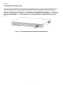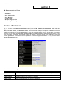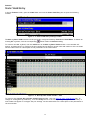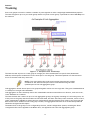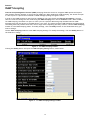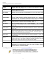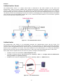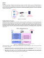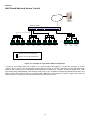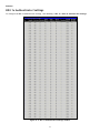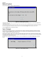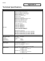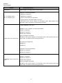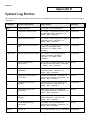
1
Conceptronic
CB100S24S & CB100S48S
User Manual
©Copyright 2008. All rights reserved.
ENGLISH
Table of Contents
Preface...............................................................................................................................................iv
Intended Readers....................................................................................................................................v
Typographical Conventions ........................................................................................................................v
Notes, Notices, and Cautions......................................................................................................................v
Safety Instructions .................................................................................................................................vi
Safety Cautions .................................................................................................................................vi
General Precautions for Rack-Mountable Products....................................................................................... vii
Protecting Against Electrostatic Discharge ............................................................................................... viii
Introduction .............................................................................................................................1
CB100S24S/CB100S48S............................................................................................................................. 1
Features .......................................................................................................................................... 1
Ports .............................................................................................................................................. 2
Front-Panel Components ...................................................................................................................... 4
LEDs ............................................................................................................................................... 5
Installing the SFP ports ........................................................................................................................ 6
Installation ..............................................................................................................................7
Package Contents ............................................................................................................................... 7
Before You Connect to the Network ......................................................................................................... 7
Installing the Switch without the Rack ...................................................................................................... 8
Installing the Switch in a Rack................................................................................................................ 8
Mounting the Switch in a Standard 19" Rack ............................................................................................... 9
Connecting the Switch .............................................................................................................. 10
Switch to End Node............................................................................................................................ 10
Switch to Hub or Switch ...................................................................................................................... 11
Introduction to Switch Management ............................................................................................. 12
Management Options ............................................................................................................................. 12
Web-based Management Interface.......................................................................................................... 12
Connecting the Console Port (DCE RS-232 DB-9).......................................................................................... 12
First Time Connecting to the Switch ....................................................................................................... 14
Web-based Switch Configuration ................................................................................................. 15
Introduction ........................................................................................................................................ 15
Login to Web Manager ........................................................................................................................ 15
Web-based User Interface .................................................................................................................... 16
Web Pages ...................................................................................................................................... 17
Administration ........................................................................................................................ 18
Device Information................................................................................................................................ 18
IP Address .......................................................................................................................................... 19
Port Configuration ................................................................................................................................ 20
Port Settings.................................................................................................................................... 21
Port Description................................................................................................................................ 22
User Accounts...................................................................................................................................... 24
ii
ENGLISH
Port Mirroring ...................................................................................................................................... 25
TFTP Services ...................................................................................................................................... 26
Multiple Image Services .......................................................................................................................... 27
Firmware Information......................................................................................................................... 27
Config Firmware Image ....................................................................................................................... 27
Forwarding & Filtering ........................................................................................................................... 27
Unicast Forwarding ............................................................................................................................ 27
Multicast Forwarding .......................................................................................................................... 28
Multicast Filtering Mode ...................................................................................................................... 29
L2 Features............................................................................................................................ 30
VLANs ............................................................................................................................................... 30
Static VLAN Entry .............................................................................................................................. 34
Trunking ............................................................................................................................................ 36
Link Aggregation ............................................................................................................................... 37
IGMP Snooping ..................................................................................................................................... 38
Static Router Ports Settings .................................................................................................................. 40
Spanning Tree...................................................................................................................................... 41
STP Bridge Global Settings ................................................................................................................... 43
STP Port Settings............................................................................................................................... 45
CoS ...................................................................................................................................... 47
802.1p Default Priority ........................................................................................................................... 50
802.1p User Priority .............................................................................................................................. 51
Security ................................................................................................................................ 52
802.1X............................................................................................................................................... 52
802.1x Authenticator Settings ............................................................................................................... 57
Local Users...................................................................................................................................... 60
RADIUS Server .................................................................................................................................. 63
Monitoring ............................................................................................................................. 64
MAC Address ....................................................................................................................................... 64
IGMP Snooping Group ............................................................................................................................. 66
Browse Router Port ............................................................................................................................... 67
Port Access Control ............................................................................................................................... 67
RADIUS Authentication ........................................................................................................................ 67
Auth State .......................................................................................................................................... 69
Reset ................................................................................................................................................ 70
Reboot System ..................................................................................................................................... 71
Save Changes ...................................................................................................................................... 71
Logout............................................................................................................................................... 72
Technical Specifications ............................................................................................................ 73
System Log Entries................................................................................................................... 77
Cable Lengths ......................................................................................................................... 85
Glossary ................................................................................................................................ 86
iii
ENGLISH
Preface
The CB100S24S/CB100S48S User Manual is divided into sections that describe the system installation and operating
instructions with examples.
Section 1: Introduction
Describes the Switch and its features.
Section 2: Installation
Helps you get started with the basic installation of the Switch and also describes the front panel, rear panel, side
panels, and LED indicators of the Switch.
Section 3: Connecting the Switch
Tells how you can connect the Switch to your Ethernet/Fast Ethernet network.
Section 4: Introduction to Switch Management
Introduces basic Switch management features, including password protection, SNMP settings, IP address
assignment and connecting devices to the Switch.
Section 5: Introduction to Web-based Switch Management
Talks about connecting to and using the Web-based switch management feature on the Switch.
Section 6: Administration
A detailed discussion about configuring the basic functions of the Switch, including IP Address, Port
Configuration, User Accounts, Port Mirroring, TFTP Services, Multiple Image Services and Forwarding & Filtering.
Section 7: Layer 2 Features
A discussion of Layer 2 features of the Switch, including VLAN, Trunking, IGMP Snooping, and Spanning Tree.
Section 8: CoS
Discussion on the CoS features on the Switch, including 802.1p Default Priority and 802.1p User Priority.
Section 9: Security
A discussion on the Security functions on the Switch, including SSH, 802.1X.
Section 10: Monitoring
Features information on Monitoring including MAC Address, IGMP Snooping Group, Browse Router Port and Port
Access Control.
Section 11: Maintenance
Information on Switch utility functions such as Reset, Reboot System, Save Changes and Logout.
Appendix A: Technical Specifications
Technical specifications for the CB100S24S and CB100S48S.
Appendix B: System Log Entries
Information on the System Log Entries.
Appendix C: Cable Lengths
Information on cable types and maximum distances.
Appendix D: Glossary
Lists definitions for terms and acronyms used in this document.
iv
ENGLISH
Intended Readers
The CB100S24S/CB100S48S User Manual contains information for setup and management of the Switch. The term,
“the Switch” will be used when referring to both switches. This manual is intended for network managers familiar
with network management concepts and terminology.
Typographical Conventions
Convention
Description
[]
In a command line, square brackets indicate an optional entry. For example: [copy
filename] means that optionally you can type copy followed by the name of the file. Do
not type the brackets.
Bold font
Indicates a button, a toolbar icon, menu, or menu item. For example: Open the File menu
and choose Cancel. Used for emphasis. May also indicate system messages or prompts
appearing on your screen. For example: You have mail. Bold font is also used to represent
filenames, program names and commands. For example: use the copy command.
Boldface Typewriter
Font
Indicates commands and responses to prompts that must be typed exactly as printed in
the manual.
Initial capital letter
Indicates a window name. Names of keys on the keyboard have initial capitals. For
example: Click Enter.
Italics
Indicates a window name or a field. Also can indicate a variables or parameter that is
replaced with an appropriate word or string. For example: type filename means that you
should type the actual filename instead of the word shown in italic.
Menu Name > Menu
Option
Menu Name > Menu Option Indicates the menu structure. Device > Port > Port
Properties means the Port Properties menu option under the Port menu option that is
located under the Device menu.
Notes, Notices, and Cautions
A NOTE indicates important information that helps you make better use of your device.
A NOTICE indicates either potential damage to hardware or loss of data and tells you how
to avoid the problem.
A CAUTION indicates a potential for property damage, personal injury, or death.
v
ENGLISH
Safety Instructions
Use the following safety guidelines to ensure your own personal safety and to help protect your system from
potential damage. Throughout this document, the caution icon ( ) is used to indicate cautions and precautions
that you need to review and follow.
Safety Cautions
To reduce the risk of bodily injury, electrical shock, fire, and damage to the equipment, observe the following
precautions:
•
Observe and follow service markings.
•
Do not service any product except as explained in your system documentation.
•
Opening or removing covers that are marked with the triangular symbol with a lightning bolt may
expose you to electrical shock.
•
Only a trained service technician should service components inside these compartments.
•
If any of the following conditions occur, unplug the product from the electrical outlet and replace the part or
contact your trained service provider:
•
The power cable, extension cable, or plug is damaged.
•
An object has fallen into the product.
•
The product has been exposed to water.
•
The product has been dropped or damaged.
•
The product does not operate correctly when you follow the operating instructions.
•
•
Keep your system away from radiators and heat sources. Also, do not block cooling vents.
Do not spill food or liquids on your system components, and never operate the product in a wet environment.
If the system gets wet, see the appropriate section in your troubleshooting guide or contact your trained
service provider.
Do not push any objects into the openings of your system. Doing so can cause fire or electric shock by shorting
out interior components.
Use the product only with approved equipment.
Allow the product to cool before removing covers or touching internal components.
Operate the product only from the type of external power source indicated on the electrical ratings label. If
you are not sure of the type of power source required, consult your service provider or local power company.
•
•
•
•
•
•
•
•
•
•
•
Also, be sure that attached devices are electrically rated to operate with the power available in your location.
Use only approved power cable(s). If you have not been provided with a power cable for your system or for any
AC-powered option intended for your system, purchase a power cable that is approved for use in your country.
The power cable must be rated for the product and for the voltage and current marked on the product's
electrical ratings label. The voltage and current rating of the cable should be greater than the ratings marked
on the product.
To help prevent electric shock, plug the system and peripheral power cables into properly grounded electrical
outlets. These cables are equipped with three-prong plugs to help ensure proper grounding. Do not use
adapter plugs or remove the grounding prong from a cable. If you must use an extension cable, use a 3-wire
cable with properly grounded plugs.
Observe extension cable and power strip ratings. Make sure that the total ampere rating of all products
plugged into the extension cable or power strip does not exceed 80 percent of the ampere ratings limit for the
extension cable or power strip.
To help protect your system from sudden, transient increases and decreases in electrical power, use a surge
suppressor, line conditioner, or uninterruptible power supply (UPS).
Position system cables and power cables carefully; route cables so that they cannot be stepped on or tripped
over. Be sure that nothing rests on any cables.
Do not modify power cables or plugs. Consult a licensed electrician or your power company for site
modifications. Always follow your local/national wiring rules.
vi
ENGLISH
•
When connecting or disconnecting power to hot-pluggable power supplies, if offered with your system, observe
the following guidelines:
•
Install the power supply before connecting the power cable to the power supply.
•
Unplug the power cable before removing the power supply.
•
If the system has multiple sources of power, disconnect power from the system by unplugging all power
cables from the power supplies.
•
Move products with care; ensure that all casters and/or stabilizers are firmly connected to the system. Avoid
sudden stops and uneven surfaces.
General Precautions for Rack-Mountable Products
Observe the following precautions for rack stability and safety. Also, refer to the rack installation documentation
accompanying the system and the rack for specific caution statements and procedures:
•
•
•
•
•
•
•
•
•
Systems are considered to be components in a rack. Thus, "component" refers to any system as well as to
various peripherals or supporting hardware.
Before working on the rack, make sure that the stabilizers are secured to the rack, extended to the floor, and
that the full weight of the rack rests on the floor. Install front and side stabilizers on a single rack or front
stabilizers for joined multiple racks before working on the rack.
Always load the rack from the bottom up, and load the heaviest item in the rack first.
Make sure that the rack is level and stable before extending a component from the rack.
Use caution when pressing the component rail release latches and sliding a component into or out of a rack;
the slide rails can pinch your fingers.
After a component is inserted into the rack, carefully extend the rail into a locking position, and then slide the
component into the rack.
Do not overload the AC supply branch circuit that provides power to the rack. The total rack load should not
exceed 80 percent of the branch circuit rating.
Ensure that proper airflow is provided to components in the rack.
Do not step on or stand on any component when servicing other components in a rack.
NOTE: A qualified electrician must perform all connections to DC power and to safety
grounds. All electrical wiring must comply with applicable local, regional or national codes
and practices.
CAUTION: Never defeat the ground conductor or operate the equipment in the absence of
a suitably installed ground conductor. Contact the appropriate electrical inspection
authority or an electrician if you are uncertain that suitable grounding is available.
CAUTION: The system chassis must be positively grounded to the rack cabinet frame. Do
not attempt to connect power to the system until grounding cables are connected. A
qualified electrical inspector must inspect completed power and safety ground wiring. An
energy hazard will exist if the safety ground cable is omitted or disconnected.
CAUTION: Do not replace the battery with an incorrect type. The risk of explosion exists
if the replacement battery is not the correct lithium battery type. Dispose of used
batteries according to the instructions.
vii
ENGLISH
Protecting Against Electrostatic Discharge
Static electricity can harm delicate components inside your system. To prevent static damage, discharge static
electricity from your body before you touch any of the electronic components, such as the microprocessor. You can
do so by periodically touching an unpainted metal surface on the chassis.
You can also take the following steps to prevent damage from electrostatic discharge (ESD):
1. When unpacking a static-sensitive component from its shipping carton, do not remove the component from
the antistatic packing material until you are ready to install the component in your system. Just before
unwrapping the antistatic packaging, be sure to discharge static electricity from your body.
2. When transporting a sensitive component, first place it in an antistatic container or packaging.
3. Handle all sensitive components in a static-safe area. If possible, use antistatic floor pads, workbench pads
and an antistatic grounding strap.
viii
ENGLISH
Section 1
Introduction
•
•
•
•
•
•
CB100S24S/ CB100S48S Switch Description
Features
Ports
Front-Panel Components
Side Panel Description
Rear Panel Description
CB100S24S/CB100S48S
These Switches provide unsurpassed performance, fault tolerance, scalable flexibility, robust security, standardbased interoperability and impressive technology to future-proof departmental and enterprise network
deployments with an easy migration path.
The following manual describes the installation, maintenance, and configurations concerning the CB100S24S,
CB100S48S. These Switches are identical in configuration and very similar in basic hardware and consequentially,
most of the information in this manual will be universal to both switches. Corresponding screen pictures of the web
manager may be taken from both of these switches but the configuration will be identical, except for varying port
counts. For the remainder of this document, we will use the CB100S48S as the Switch in question for examples,
screen shots, configurations, and explanations.
Features
•
•
•
•
•
•
•
•
•
•
•
•
•
•
•
•
•
Address table: Supports up to 8K MAC addresses per device
Address table: Supports up to 256 static MAC entries.
Jumbo Frame: Supports Tag Frame: 2048bytes, Un-Tag Frame:2044 bytes (maximum)
IGMP Snooping support
IGMP Snooping Fast Leave
IEEE 802.1D STP Compliance
IEEE 802.1w RSTP
Supports Port Trunking
Supports Port Mirroring
IEEE 802.1Q VLAN
Supports VLAN Groups
IEEE 802.1p Priority Queues
IEEE 802.1x Port-based and MAC-based Access Control
Management: Web-based management
Supports BootP/DHCP client
Supports Dual Image and Port description
User Account Level: User Level (reader) and Administration Level (privilege)
1
ENGLISH
Ports
The following table lists the relative ports that are present within each switch as well as the features and
compatibility for each port type present in the CB100S24S and CB100S48S:
CB100S24S
Description
Twenty-four 10/100BASE-T
Compliant to following standards,
IEEE 802.3 compliance
IEEE 802.3u compliance
Support Half/Full-Duplex operations
All ports support Auto MDI-X/MDI-II cross over
IEEE 802.3x Flow Control support for Full-Duplex mode, Back Pressure
when Half-Duplex mode, and Head-of-line blocking prevention.
Two 1000Base-T/SFP Combo Ports
2 combo 1000BASE-T/SFP ports
1000BASE-T ports compliant to following standards:
IEEE 802.3 compliance
IEEE 802.3u compliance
IEEE 802.3ab compliance
Support Full-Duplex operations
IEEE 802.3x Flow Control support for Full-Duplex mode, back pressure
when Half-Duplex mode, and Head-of-line blocking prevention
SFP Transceivers Supported:
1000BASE-LX
1000BASE-SX
Compliant to following standards:
IEEE 802.3z compliance
IEEE 802.3u compliance
Two 1000Base-T Ports
1000BASE-T ports compliant to following standards:
IEEE 802.3 compliance
IEEE 802.3u compliance
IEEE 802.3ab compliance
Support Full-Duplex operations
IEEE 802.3x Flow Control support for Full-Duplex mode, back pressure
when Half-Duplex mode, and Head-of-line blocking prevention
One female DCE RS-232 DB-9 console
port
DCE RS-232 DB-9 for loading factory reset purpose
2
ENGLISH
CB100S48S
Description
Forty-eight
10/100BASE-T
Compliant to following standards,
IEEE 802.3 compliance
IEEE 802.3u compliance
Support Half/Full-Duplex operations
All ports support Auto MDI-X/MDI-II cross over
IEEE 802.3x Flow Control support for Full-Duplex mode, Back Pressure when Half-Duplex
mode, and Head-of-line blocking prevention.
Two 1000BaseT/SFP
Combo
Ports
2 combo 1000BASE-T/SFP ports
1000BASE-T ports compliant to following standards:
IEEE 802.3 compliance
IEEE 802.3u compliance
IEEE 802.3ab compliance
Support Full-Duplex operations
IEEE 802.3x Flow Control support for Full-Duplex mode, back pressure when Half-Duplex
mode, and Head-of-line blocking prevention
SFP Transceivers Supported:
1000BASE-LX
1000BASE-SX
Compliant to following standards:
IEEE 802.3z compliance
IEEE 802.3u compliance
Two 1000Base-T
Ports
1000BASE-T ports compliant to following standards:
IEEE 802.3 compliance
IEEE 802.3u compliance
IEEE 802.3ab compliance
Support Full-Duplex operations
IEEE 802.3x Flow Control support for Full-Duplex mode, back pressure when Half-Duplex
mode, and Head-of-line blocking prevention
One female DCE
RS-232
DB-9
console port
DCE RS-232 DB-9 for loading factory reset purpose
NOTE: The SFP combo ports on the Switch cannot be used simultaneously with the
corresponding 1000BASE-T ports. If both ports are in use at the same time (ex. port 25 of the
SFP and port 25 of the 1000BASE-T), the SFP ports will take priority over the combo ports
and render the 1000BASE-T ports inoperable.
3
ENGLISH
Front-Panel Components
CB100S24S
•
•
•
•
•
Twenty-four 10/100Mbps BASE-T ports
Two Combo 1000BASE-T/SFP ports located to the right
Two 1000BASE-T ports located to the right
One female DCE RS-232 DB-9 console port
LEDs for Power, Console, Link/Act/Speed for each port
Figure 1- 1. Front Panel of the CB100S24S
CB100S48S
•
•
•
•
•
Forty-eight 10/100Mbps BASE-T ports
Two Combo 1000BASE-T/SFP ports located to the right
Two 1000BASE-T ports located to the right
One female DCE RS -232 DB-9 console port
LEDs for Power, Console, Link/Act/Speed for each port
Figure 1- 2. Front Panel of the CB100S48S
4
ENGLISH
LEDs
The following table lists the LEDs along with their corresponding description:
Location
LED Indicative Color
Power
Green
Per Device
Console
Green
Status
Description
Solid Light
Power On
Light off
Power Off
Solid Light
Console on
Blinking
POST is in progress/ POST is failure.
Light off
Console off
Solid Green
Blinking Green
LED Per 10/100 Mbps
Port
Link/Act/Speed
Green/Amber
Solid Amber
Blinking Amber
Light off
Solid Green
Blinking Green
Link/Act/Speed
mode for
Green/Amber
1000BASE-T ports
Solid Amber
Blinking Amber
LED Per GE Port
Light off
Solid Green
Blinking Green
Link/Act/Speed
mode for SFP
ports
Green/Amber
Solid Amber
Blinking Amber
Light off
5
When there is a secure 100Mbps Fast
Ethernet connection (or link) at any
of the ports.
When there is reception or
transmission (i.e. Activity—Act) of
data occurring at a Fast Ethernet
connected port.
When there is a secure 10Mbps
Ethernet connection (or link) at any
of the ports.
When there is reception or
transmission (i.e. Activity—Act) of
data occurring at an Ethernet
connected port.
No link
When there is a secure 1000Mbps
connection (or link) at any of the
ports.
When there is reception or
transmission (i.e. Activity--Act) of
data occurring at a 1000Mbps
connected port.
When there is a secure 10/100Mbps
Fast Ethernet connection (or link) at
any of the ports.
When there is reception or
transmission (i.e. Activity—Act) of
data occurring at a Fast Ethernet
connected port.
No link
When there is a secure 1000Mbps
connection (or link) at the ports.
When there is reception or
transmission (i.e. Activity--Act) of
data occurring at a 1000Mbps
connected port.
When there is a secure 100Mbps
connection (or link) at any of the
ports.
When there is reception or
transmission (i.e. Activity—Act) of
data occurring at the ports.
No link
ENGLISH
Installing the SFP ports
These Switches are equipped with SFP (Small Form Factor Portable) ports, which are to be used with fiber-optical
transceiver cabling in order to uplink various other networking devices for a gigabit link that may span great
distances. These SFP ports support full-duplex transmissions, have auto-negotiation and can be used with the
INFINEON / V23818-K15-B57((1000BASE-LX) -- 1310nm INFINEON / V23818-K305-B57(1000BASE-SX) -- 850nm Finisar /
FTRJ-1319-7D (1000BASE-LX) -- 1310nm CORETEK OPTO CT-0155TSP-MB5L(Single Mode 100BASE-FX), CT-0155NSPMB2L (Multi Mode 100BASE-FX) -- 1310nm transceivers. See the figure below for installing the SFP ports in the
Switch.
Figure 1- 3. Inserting the fiber-optic transceivers into the Switch
6
ENGLISH
SECTION 2
Installation
•
•
•
•
•
Package Contents
Before You Connect to the Network
Installing the Switch without the Rack
Rack Installation
Power On
Package Contents
Open the shipping carton of the Switch and carefully unpack its contents. The carton should contain the following
items:
•
•
•
•
•
•
•
Conceptronic 24/48 Ports 10/100Mbps Smart Switch
AC Power cable
DCE RS-232 console cable
Switch Mounting Kit (2 brackets with screws)
4 rubber product-feet
Product CD-ROM
This Quick Installation Guide
If any item is missing or damaged, please contact your local Reseller for replacement.
Before You Connect to the Network
The site where you install the Switch may greatly affect its performance. Please follow these guidelines for setting
up the Switch.
•
Install the Switch on a sturdy, level surface that can support at least 4.24kg (9.35lbs) of weight. Do not
place heavy objects on the Switch.
•
The power outlet should be within 1.82 meters (6 feet) of the Switch.
•
Visually inspect the power cord and see that it is fully secured to the AC/DC power port.
•
Make sure that there is proper heat dissipation from and adequate ventilation around the Switch. Leave
at least 10 cm (4 inches) of space at the front and rear of the Switch for ventilation.
•
Install the Switch in a fairly cool and dry place for the acceptable temperature and humidity operating
ranges.
•
Install the Switch in a site free from strong electromagnetic field generators (such as motors),
vibration, dust, and direct exposure to sunlight.
•
When installing the Switch on a level surface, attach the rubber feet to the bottom of the device. The
rubber feet cushion the Switch, protect the casing from scratches and prevent it from scratching other
surfaces.
7
ENGLISH
Installing the Switch without the Rack
When installing the Switch on a desktop or shelf, the rubber feet included with the Switch should first be attached.
Attach these cushioning feet on the bottom at each corner of the device. Allow enough ventilation space between
the Switch and any other objects in the vicinity.
Figure 2 - 1. Prepare Switch for installation on a desktop or shelf
Installing the Switch in a Rack
The Switch can be mounted in a standard 19" rack. Use the following images to guide you.
Figure 2 - 2. Fasten mounting brackets to Switch
Fasten the mounting brackets to the Switch using the screws provided. With the brackets attached securely, users
can mount the Switch in a standard rack as shown in the next figure.
8
ENGLISH
Mounting the Switch in a Standard 19" Rack
CAUTION: Installing systems in a rack without the front and side stabilizers installed could cause the
rack to tip over, potentially resulting in bodily injury under certain circumstances. Therefore, always
install the stabilizers before installing components in the rack. After installing components in a rack,
do not pull more than one component out of the rack on its slide assemblies at one time. The weight
of more than one extended component could cause the rack to tip over and may result in injury.
Figure 2 - 3. Installing Switch in a rack
Power on AC Power
Plug one end of the AC power cord into the power connector of the Switch and the other end into the local power
source outlet.
After the Switch is powered on, the LED indicators will momentarily blink. This blinking of the LED indicators
represents a reset of the system.
Power Failure
For AC power supply units, as a precaution, in the event of a power failure, unplug the Switch. When power has
resumed, plug the Switch back in.
CAUTION: Installing systems in a rack without the front and side stabilizers installed could cause the
rack to tip over, potentially resulting in bodily injury under certain circumstances. Therefore, always
install the stabilizers before installing components in the rack. After installing components in a rack,
do not pull more than one component out of the rack on its slide assemblies at one time. The weight
of more than one extended component could cause the rack to tip over and may result in injury.
.
9
ENGLISH
Section 3
Connecting the Switch
•
•
•
Switch to End Node
Switch to Hub or Switch
Connecting to Network Backbone or Server
NOTE: All 10/100/1000Mbps NWay Ethernet ports can support both MDI-II
and MDI-X connections.
Switch to End Node
End nodes include PCs outfitted with a 10, 100 or 1000 Mbps RJ 45 Ethernet/Fast Ethernet Network Interface Card
(NIC) and most routers. An end node can be connected to the Switch via a twisted-pair Category 3, 4, or 5 UTP/STP
cable. The end node should be connected to any of the ports of the Switch.
Figure 3- 1. Switch connected to an end node
The Link/Act LEDs for each UTP port will light green or amber when the link is valid. A blinking LED indicates
packet activity on that port.
10
ENGLISH
Switch to Hub or Switch
These connections can be accomplished in a number of ways using a normal cable.
•
A 10BASE-T hub or switch can be connected to the Switch via a twisted-pair Category 3, 4 or 5 UTP/STP cable.
•
A 100BASE-TX hub or switch can be connected to the Switch via a twisted-pair Category 5 UTP/STP cable.
•
A 1000BASE-T switch can be connected to the Switch via a twisted pair Category 5e UTP/STP cable.
•
A switch supporting a fiber-optic uplink can be connected to the Switch’s SFP ports via fiber-optic cabling.
Figure 3- 2. Switch connected to a normal (non-Uplink) port on a hub or switch using a straight or crossover
cable
NOTICE: When the SFP transceiver acquires a link, the associated integrated
10/100/1000BASE-T port is disabled.
11
ENGLISH
Section 4
Introduction to Switch Management
•
•
•
•
•
•
•
•
Management Options
Web-based Management Interface
Managing User Accounts
Command Line Console Interface through the Serial Port
Connecting the Console Port (RS-232 DCE)
First Time Connecting to the Switch
Password Protection
IP Address Assignment
Management Options
This system may be managed through the web-based management, accessible through a web browser.
Web-based Management Interface
After you have successfully installed the Switch, you can configure the Switch, monitor the LED panel, and display
statistics graphically using a web browser, such as Netscape Navigator (version 6.2.3 and higher) or Microsoft®
Internet Explorer (version 6.0).
Connecting the Console Port (DCE RS-232 DB-9)
The Switch provides an RS-232 serial port that enables a connection to a computer or terminal for loading factory
reset purposes. This port is a female DB-9 connector, implemented as a data terminal equipment (DTE) connection.
To use the console port, you need the following equipment:
•
A terminal or a computer with both a serial port and the ability to emulate a terminal.
•
A null modem or crossover RS-232 cable with a female DB-9 connector for the console port on the Switch.
To connect a terminal to the console port:
1. Connect the female connector of the RS-232 cable directly to the console port on the Switch, and tighten
the captive retaining screws.
2. Connect the other end of the cable to a terminal or to the serial connector of a computer running terminal
emulation software. Set the terminal emulation software as follows:
3. Select the appropriate serial port (COM port 1 or COM port 2).
4. Set the data rate to 9600 baud.
5. Set the data format to 8 data bits, 1 stop bit, and no parity.
6. Set flow control to none.
7. Under Properties, select VT100 for Emulation mode.
8. Select Terminal keys for Function, Arrow, and Ctrl keys. Ensure that you select Terminal keys (not
Windows keys).
NOTE: When you use HyperTerminal with the Microsoft® Windows® 2000 operating system, ensure that you have Windows 2000 Service Pack 2 or later installed. Windows 2000
Service Pack 2 allows you to use arrow keys in HyperTerminal's VT100 emulation. See
www.microsoft.com for information on Windows 2000 service packs.
12
ENGLISH
9. After you have correctly set up the terminal, plug the power cable into the power receptacle on the back
of the Switch. The boot sequence appears in the terminal.
10. After the boot sequence completes, the console login screen displays.
11. If you have not logged into the command line interface (CLI) program, press the Enter key at the User
name and password prompts. There is no default user name and password for the Switch. The administrator
must first create user names and passwords. If you have previously set up user accounts, log in and
continue to configure the Switch.
12. When you have completed your tasks, exit the session with the logout command or close the emulator
program.
13. Make sure the terminal or PC you are using to make this connection is configured to match these settings.
If you are having problems making this connection on a PC, make sure the emulation is set to VT-100. You will be
able to set the emulation by clicking on the File menu in you HyperTerminal window, clicking on Properties in the
drop-down menu, and then clicking the Settings tab. This is where you will find the Emulation options. If you still
do not see anything, try rebooting the Switch by disconnecting its power supply.
Once connected to the console, the screen below will appear on your console screen. This is where the user will
enter commands to perform all the available management functions. The Switch will prompt the user to enter a
user name and a password. Upon the initial connection, there is no user name or password and therefore just press
enter twice to access the command line interface.
CB100S48S Fast Ethernet Switch Command Line Interface
Firmware: Build 1.00-B11
Copyright (C) 2008 2L International B.V. All rights reserved.
UserName:
Figure 4- 1. Initial screen after first connection
13
ENGLISH
First Time Connecting to the Switch
The Switch supports user-based security that can allow you to prevent unauthorized users from accessing the
Switch or changing its settings. This section tells how to log onto the Switch.
NOTE: The passwords used to access the Switch are case-sensitive; therefore, "S" is
not the same as "s."
When you first connect to the Switch, you will be presented with the first login screen.
NOTE: Press Ctrl+R to refresh the screen. This command can be used at any time to
force the console program in the Switch to refresh the console screen.
Press Enter in both the Username and Password fields. You will be given access to the command prompt
CB100S48S:1# shown below:
There is no initial username or password. Leave the Username and Password fields blank.
CB100S48S Fast Ethernet Switch Command Line Interface
Firmware: Build 1.00-B11
Copyright (C) 2008 2L International B.V. All rights reserved.
UserName:
Password:
CB100S48S:1#
Figure 4- 2. Command Prompt
14
ENGLISH
Section 5
Web-based Switch Configuration
•
•
•
•
•
•
•
•
•
•
Introduction
Login to Web manager
Web-Based User Interface
Basic Setup
Reboot
Basic Switch Setup
Network Management
Switch Utilities
Network Monitoring
IGMP Snooping Status
Introduction
All software functions of the Switch can be managed, configured and monitored via the embedded web-based
(HTML) interface. The Switch can be managed from remote stations anywhere on the network through a standard
browser such as Opera, Netscape Navigator/Communicator, or Microsoft Internet Explorer. The browser acts as a
universal access tool and can communicate directly with the Switch using the HTTP protocol.
Login to Web Manager
To begin managing the Switch, simply run the browser you have installed on your computer and point it to the IP
address you have defined for the device. The URL in the address bar should read something like:
http://123.123.123.123, where the numbers 123 represent the IP address of the Switch.
NOTE: The Factory default IP address for the Switch is 192.168.0.200
This opens the management module's user authentication window, as seen below.
Figure 5- 1. Enter Network Password dialog
There is no user name of password by default, click OK. This will open the Web-based user interface. The Switch
management features available in the web-based manager are explained below.
15
ENGLISH
Web-based User Interface
The user interface provides access to various Switch configuration and management windows, allows you to view
performance statistics, and permits you to graphically monitor the system status.
Areas of the User Interface
The figure below shows the user interface. The user interface is divided into three distinct areas as described in the
table.
Area 2
Area 3
Area 1
Figure 5- 2. Main Web-Manager page
Area
Function
Area 1
Select the folder or window to be displayed. The folder icons can be opened to display the hyperlinked window buttons and subfolders contained within them. Click the 2L International B.V. logo
to go to the 2L International B.V. website.
Area 2
Presents a graphical near real-time image of the front panel of the Switch. This area displays the
Switch's ports and expansion modules, showing port activity, duplex mode, or flow control,
depending on the specified mode.
Various areas of the graphic can be selected for performing management functions, including port
configuration.
Area 3
Presents switch information based on your selection and the entry of configuration data.
16
ENGLISH
NOTICE: Any changes made to the Switch configuration during the
current session must be saved in the Save Changes web menu (explained
below).
Web Pages
When you connect to the management mode of the Switch with a web browser, a login window is displayed. Enter a
user name and password to access the Switch's management mode.
Below is a list and description of the main folders available in the web interface:
Administration
Contains windows concerning configuring the basic functions of the Switch, including IP Address, Port
Configuration, User Accounts, Port Mirroring, TFTP Services, Multiple Image Services and Forwarding and
Filtering.
Layer 2 Features
Contains windows concerning Layer 2 features of the Switch, including VLAN, Trunking, IGMP Snooping, and
Spanning Tree.
CoS
Contains windows concerning, 802.1P Default Priority and 802.1P User Priority.
Security
Contains windows for 802.1x.
Monitoring
Contains windows MAC Address, Switch Log, IGMP Snooping Group, Browse Router Port, and Port Access Control.
Switch Maintenance
Contains information regarding Reset, Reboot System, Save Changes, and Logout.
NOTE: Be sure to configure the user name and password in the User
Accounts window before connecting the Switch to the greater network.
17
ENGLISH
Section 6
Administration
•
•
•
•
•
•
•
IP Address
Port Configuration
User Accounts
Port Mirroring
TFTP Services
Multiple Image Services
Forwarding & Filtering
Device Information
This window contains the main settings for all major functions for the Switch and appears automatically when you
log on. To return to the Device Information window, click the CB 100S48S Web Management Tool folder. The
Device Information window shows the Switch’s MAC Address (assigned by the factory and unchangeable), the Boot
PROM, Firmware Version, and Hardware Version. This information is helpful to keep track of PROM and firmware
updates and to obtain the Switch's MAC address for entry into another network device's address table, if necessary.
The user may also enter a System Name, System Location and System Contact to aid in defining the Switch, to the
user's preference. In addition, this window displays the status of functions on the Switch to quickly assess their
current global status. Some functions are hyper-linked to their configuration window for easy access from the
Device Information window.
Figure 6- 1. Device Information window
The fields that can be configured are described below:
Parameter
Description
System Name
Enter a system name for the Switch, if so desired. This name will identify it in the Switch
network.
System Location
Enter the location of the Switch, if so desired.
System Contact
Enter a contact name for the Switch, if so desired.
18
ENGLISH
IGMP Snooping
To enable system-wide IGMP Snooping capability select Enabled. IGMP snooping is Disabled
by default. Enabling IGMP snooping allows you to specify use of a multicast router only (see
below). To configure IGMP Snooping for individual VLANs, use the IGMP Snooping window
located in the IGMP Snooping folder contained in the L2 Features folder.
Switch 802.1x
MAC Address may enable by port or the Switch’s 802.1x function; the default is Disabled.
This field must be enabled to view and configure certain windows for 802.1x. More
information regarding 802.1x, its functions and implementation can be found later in the
頁
802.1x folder in the Security folder.
:
19
Port-Based 802.1x specifies that ports configured for 802.1x are initialized based on the
port number only and are subject to any authorization parameters configured.
MAC-based Authorization specifies that ports configured for 802.1x are initialized based on
the port number and the MAC address of the computer being authorized and are then
subject to any authorization parameters configured.
Auth Protocol
頁
:
19
There are two options in this drop-down menu, RADIUS EAP and Local. This determines
which authorization function will be assigned to 802.1x.
Click Apply to implement changes made.
IP Address
The IP address may be set using the web manager, you must access the IP Address window located in the
Administration folder.
To configure the Switch's IP address:
Open the Administration folder and click the IP Address link. The web manager will display the Switch's current IP
settings in the IP Address window, as seen below.
Figure 6- 2. IP Address Settings window
To manually assign the Switch's IP address, subnet mask, and default gateway address:
1. Select Manual from the Get IP From drop-down menu.
2. Enter the appropriate IP Address and Subnet Mask.
3. If you want to access the Switch from a different subnet from the one it is installed on, enter the IP address
of the Default Gateway. If you will manage the Switch from the subnet on which it is installed, you can
leave the default address (0.0.0.0) in this field.
4. If no VLANs have been previously configured on the Switch, you can use the default VLAN Name. The
default VLAN contains all of the Switch ports as members. If VLANs have been previously configured on the
Switch, you will need to enter the VLAN Name of the VLAN that contains the port connected to the
management station that will access the Switch. The Switch will allow management access from stations
with the same VID listed here.
19
ENGLISH
NOTE: The Switch's factory default IP address is 192.168.0.200 with a
subnet mask of 255.255.255.0 and a default gateway of 192.168.0.1.
To use the BOOTP or DHCP protocols to assign the Switch an IP address, subnet mask, and default gateway address:
Use the Get IP From pull-down menu to choose from BOOTP or DHCP. This selects how the Switch will be assigned
an IP address on the next reboot.
The IP Address Settings options are:
Parameter
Description
BOOTP
The Switch will send out a BOOTP broadcast request when it is powered up. The BOOTP
protocol allows IP addresses, network masks, and default gateways to be assigned by a central
BOOTP server. If this option is set, the Switch will first look for a BOOTP server to provide it
with this information before using the default or previously entered settings.
DHCP
The Switch will send out a DHCP broadcast request when it is powered up. The DHCP protocol
allows IP addresses, network masks, and default gateways to be assigned by a DHCP server. If
this option is set, the Switch will first look for a DHCP server to provide it with this information
before using the default or previously entered settings.
Manual
Allows the entry of an IP address, Subnet Mask, and a Default Gateway for the Switch. These
fields should be of the form xxx.xxx.xxx.xxx, where each xxx is a number (represented in
decimal form) between 0 and 255. This address should be a unique address on the network
assigned for use by the network administrator.
Subnet Mask
A Bitmask that determines the extent of the subnet that the Switch is on. Should be of the form
xxx.xxx.xxx.xxx, where each xxx is a number (represented in decimal) between 0 and 255. The
value should be 255.0.0.0 for a Class A network, 255.255.0.0 for a Class B network, and
255.255.255.0 for a Class C network, but custom subnet masks are allowed.
Default Gateway
IP address that determines where packets with a destination address outside the current subnet
should be sent. This is usually the address of a router or a host acting as an IP gateway. If your
network is not part of an intranet, or you do not want the Switch to be accessible outside your
local network, you can leave this field unchanged.
VLAN Name
This allows the entry of a VLAN Name from which a management station will be allowed to
manage the Switch using TCP/IP (in-band via web manager). If VLANs have not yet been
configured for the Switch, the default VLAN contains all of the Switch's ports. Any management
station that can connect to the Switch can access the Switch until a management VLAN is
specified.
Click Apply to allow changes to take effect.
Port Configuration
This section contains information for configuring various attributes and properties for individual physical ports,
including port speed and flow control.
20
ENGLISH
Port Settings
Click Administration > Port Configuration > Port Settings to display the following window:
To configure switch ports:
1. Choose the port or sequential range of ports using the From…To… port pull-down menus.
Use the remaining pull-down menus to configure the parameters described below:
Figure 6- 3. Port Configuration window
21
ENGLISH
The following parameters can be configured:
Parameter
Description
From…. To
Use the pull-down menus to select the port or range of ports to be configured.
State
Toggle this field to either enable or disable a given port or group of ports.
Speed/Duplex
Toggle the Speed/Duplex field to either select the speed and duplex/half-duplex state of the
port. Auto denotes auto-negotiation between 10 and 100 Mbps devices, in full- or half-duplex.
The Auto setting allows the port to automatically determine the fastest settings the device
the port is connected to can handle, and then to use those settings. The other options are
Auto, 10M/Half, 10M/Full, 100M/Half and 100M/Full, 1000M/Full_M and 1000M/Full_S. There
is no automatic adjustment of port settings with any option other than Auto.
The Switch allows the user to configure two types of gigabit connections; 1000M/Full_M and
1000M/Full_S. Gigabit connections only support full duplex connections and take on certain
characteristics that are different from the other choices listed.
The 1000M/Full_M (master) and 1000M/Full_S (slave) parameters refer to connections running
a 1000BASE-T cable for connection between the Switch port and other device capable of a
gigabit connection. The master setting (1000M/Full_M) will allow the port to advertise
capabilities related to duplex, speed and physical layer type. The master setting will also
determine the master and slave relationship between the two connected physical layers. This
relationship is necessary for establishing the timing control between the two physical layers.
The timing control is set on a master physical layer by a local source. The slave setting
(1000M/Full_S) uses loop timing, where the timing comes form a data stream received from
the master. If one connection is set for 1000M/Full_M, the other side of the connection must
be set for 1000M/Full_S. Any other configuration will result in a link down status for both
ports.
Flow Control
Displays the flow control status used for the various port configurations. Ports configured for
full-duplex use 802.3x flow control, half-duplex ports use backpressure flow control, and Auto
ports use an automatic selection of the two. The default is Disabled.
Medium Type
This applies only to the Combo ports. If configuring the Combo ports this defines the type of
transport medium used. SFP ports should be set at Fiber and the Combo 1000BASE-T ports
should be set at Copper.
Click Apply to implement the new settings on the Switch.
Port Description
The Switch supports a port description feature where the user may name various ports on the Switch. To assign
names to various ports, click Administration > Port Configuration > Port Description to view the following
window:
Use the From and To pull-down menu to choose a port or range of ports to describe, and then enter a description
of the port(s). Click Apply to set the descriptions in the Port Description Table.
The Medium Type applies only to the Combo ports. If configuring the Combo ports this defines the type of tranport
medium used. SFP ports should be nominated Fiber and the Combo 1000BASE-T ports should be nominated Copper.
The result will be displayed in the appropriate switch port number slot (C for copper ports and F for fiber ports).
22
ENGLISH
Figure 6- 4. Port Description window
23
ENGLISH
User Accounts
Use the User Account Management window to control user privileges. To view existing User Accounts, open the
Administration folder and click on the User Accounts link. This will open the User Account Management window,
as shown below.
Figure 6- 5. User Accounts window
To add a new user, click on the Add button.
Figure 6- 6. User Account Modify Table window
Add a new user by typing in a User Name, and New Password and retype the same password in the Confirm New
Password. Choose the level of privilege (Admin or User) from the Access Right drop-down menu.
To modify or delete an existing user, click on the Modify button for that user.
Figure 6- 7. User Account Modify Table window
Modify or delete an existing user account in the User Account Modify Table. To delete the user account, click on
the Delete button. To change the password, type in the New Password and retype it in the Confirm New Password
entry field. The level of privilege (Admin or User) can be viewed in the Access Right field.
24
ENGLISH
Port Mirroring
The Switch allows you to copy frames transmitted and received on a port and redirect the copies to another port.
You can attach a monitoring device to the mirrored port, such as a sniffer or an RMON probe, to view details about
the packets passing through the first port. This is useful for network monitoring and troubleshooting purposes. To
view the Port Mirroring window, click Port Mirroring in the Administration folder.
Figure 6- 8. Port Mirroring window
To configure a mirror port:
1. Select the Source Port from where you want to copy frames and the Target Port, which receives the copies
from the source port.
2. Select the Source Direction, Ingress, Egress, or Both and change the Status drop-down menu to Enabled.
3. Click Apply to let the changes take effect.
NOTE: You cannot mirror a fast port onto a slower port. For example, if you try to mirror the
traffic from a 100 Mbps port onto a 10 Mbps port, this can cause throughput problems. The
port you are copying frames from should always support an equal or lower speed than the
port to which you are sending the copies. Also, the target port for the mirroring cannot be a
member of a trunk group. Please note a target port and a source port cannot be the same
port.
25
ENGLISH
TFTP Services
Trivial File Transfer Protocol (TFTP) services allow the Switch's firmware to be upgraded by transferring a new
firmware file from a TFTP server to the Switch. A configuration file can also be loaded into the Switch from a TFTP
server. Switch settings can be saved to the TFTP server, and a history log can be uploaded from the Switch to the
TFTP server. The TFTP server must be running TFTP server software to perform the file transfer.
Figure 6- 9. TFTP Services window
The user also has the option of transferring firmware and configuration files to and from the internal Flash drive,
located on the Switch. Using this window, the user can add a configuration or firmware file from a TFTP server to
the flash memory, or transfer that firmware or configuration file to a TFTP server. More about configuring the
internal Flash drive can be found in the next section entitled Flash File Services.
TFTP server software is a part of many network management software packages – such as NetSight, or can be
obtained as a separate program. To update the Switch's firmware or configuration file, open the TFTP Services
hyperlink, located in the Administration folder.
The following parameters can be configured:
Parameter
Active
Description
Select a service for the TFTP server to perform from the drop down window:
•
Download Firmware - Enter the IP address of the TFTP server and specify the
location of the new firmware on the TFTP server. Click Start to record the IP
address of the TFTP server and to initiate the file transfer.
•
Download Configuration - Enter the IP address of the TFTP server, and the path
and filename for the Configuration file on the TFTP server. Click Start to record
the IP address of the TFTP server and to initiate the file transfer.
•
Upload Configuration - Enter the IP address of the TFTP server and the path and
filename for the switch settings on the TFTP server. Click Start to record the IP
address of the TFTP server and to initiate the file transfer.
Server IP Address
Enter the IP address of the server from which to download firmware or configuration files.
File Name
Enter the path and filename of the firmware or configuration file to upload or download,
located on the TFTP server.
Image ID
To select a firmware file from the internal Flash drive to which the firmware file will be
transferred.
Click Start to initiate the file transfer.
26
ENGLISH
Multiple Image Services
To configure the files located on the Flash memory, use the following windows to guide you.
Firmware Information
This window is used to view boot up firmware images.
Figure 6- 10. Firmware Information window
Config Firmware Image
The following window is used to determine which of the two firmware images will be used as the default boot file.
You can also delete either of the two images.
Figure 6- 11. Config Firmware Image window
Forwarding & Filtering
Unicast Forwarding
Open the Forwarding Filtering folder in the Configuration menu and click on the Unicast Forwarding link. This
will open the following window:
Figure 6- 12. Unicast Forwarding window
27
ENGLISH
To add or edit an entry, define the following parameters and then click Add/Modify:
Parameter
Description
VID
The VLAN ID number of the VLAN on which the above Unicast MAC address resides.
MAC Address
The MAC address to which packets will be statically forwarded. This must be a unicast
MAC address.
Port
Allows the selection of the port number on which the MAC address entered above
resides.
Click Apply to implement the changes made. To delete an entry in the Static Unicast Forwarding Table, click the
corresponding X under the Delete heading.
Multicast Forwarding
The following figure and table describe how to set up Multicast Forwarding on the Switch. Open the Forwarding
Filtering folder and click on the Multicast Forwarding link to see the entry window below:
Figure 6- 13. Multicast Forwarding Settings window
The Static Multicast Forwarding Settings window displays all of the entries made into the Switch's static multicast
forwarding table. Click the Add button to open the Setup Static Multicast Forwarding Table window, as shown
below:
Figure 6- 14. Setup Static Multicast Forwarding Table window
28
ENGLISH
The following parameters can be set:
Parameter
Description
VID
The VLAN ID of the VLAN to which the corresponding MAC address belongs.
Multicast MAC
Address
The MAC address of the static source of multicast packets. This must be a multicast MAC
address.
Port Settings
Allows the selection of ports that will be members of the static multicast group. The
options are:
None - When None is chosen, the port will not be a member of the Static Multicast Group.
Egress - The port is a static member of the multicast group.
Click Apply to implement the changes made. To delete an entry in the Static Multicast Forwarding Table, click the
corresponding X under the Delete heading. Click the Show All Multicast Forwarding Entries link to return to the
Static Multicast Forwarding Settings window.
Multicast Filtering Mode
The following figure and table describe how to set up multicast filtering mode on the Switch. Open the Forwarding
Filtering folder and click on the Multicast Filtering Mode Setup link to see the entry window below:
Figure 6- 15. Multicast Filtering Mode window
The following parameters can be set:
Parameter
Description
From/To
These two drop-down menus allow you to select a range of ports to which the filter settings
will be applied.
Mode
This drop-down menu allows you to select the action the Switch will take when it receives a
multicast packet that is to be forwarded to one of the ports in the range specified above.
•
Forward Unregistered Groups - This will instruct the Switch to forward a multicast
packet whose destination is an unregistered multicast group residing within the
range of ports specified above.
•
Filter Unregistered Groups - This will instruct the Switch to filter any multicast
packets whose destination is an unregistered multicast group residing within the
range of ports specified above.
Click Apply to implement changes made.
29
ENGLISH
Section 7
L2 Features
•
•
•
•
VLAN
Trunking
IGMP Snooping
Spanning Tree
VLANs
A Virtual Local Area Network (VLAN) is a network topology configured according to a logical scheme rather than the
physical layout. VLANs can be used to combine any collection of LAN segments into an autonomous user group that
appears as a single LAN. VLANs also logically segment the network into different broadcast domains so that packets
are forwarded only between ports within the VLAN. Typically, a VLAN corresponds to a particular subnet, although
not necessarily.
VLANs can enhance performance by conserving bandwidth, and improve security by limiting traffic to specific
domains.
A VLAN is a collection of end nodes grouped by logic instead of physical location. End nodes that frequently
communicate with each other are assigned to the same VLAN, regardless of where they are physically on the
network. Logically, a VLAN can be equated to a broadcast domain, because broadcast packets are forwarded to
only members of the VLAN on which the broadcast was initiated.
Notes about VLANs on the Switch
No matter what basis is used to uniquely identify end nodes and assign these nodes VLAN membership, packets
cannot cross VLANs without a network device performing a routing function between the VLANs.
The Switch supports IEEE 802.1Q VLANs. The port untagging function can be used to remove the 802.1Q tag from
packet headers to maintain compatibility with devices that are tag-unaware.
The Switch's default is to assign all ports to a single 802.1Q VLAN named "default."
The "default" VLAN has a VID = 1.
The member ports of Port-based VLANs may overlap, if desired.
IEEE 802.1Q VLANs
Some relevant terms:
• Tagging
The act of putting 802.1Q VLAN information into the header of a packet.
• Untagging
The act of stripping 802.1Q VLAN information out of the packet header.
• Ingress port
A port on a switch where packets are flowing into the Switch and VLAN decisions must be made.
• Egress port
A port on a switch where packets are flowing out of the Switch, either to another switch or to
an end station, and tagging decisions must be made.
IEEE 802.1Q (tagged) VLANs are implemented on the Switch. 802.1Q VLANs require tagging, which enables them to
span the entire network (assuming all switches on the network are IEEE 802.1Q-compliant).
VLANs allow a network to be segmented in order to reduce the size of broadcast domains. All packets entering a
VLAN will only be forwarded to the stations (over IEEE 802.1Q enabled switches) that are members of that VLAN,
and this includes broadcast, multicast and unicast packets from unknown sources.
VLANs can also provide a level of security to your network. IEEE 802.1Q VLANs will only deliver packets between
stations that are members of the VLAN.
Any port can be configured as either tagging or untagging. The untagging feature of IEEE 802.1Q VLANs allows
VLANs to work with legacy switches that don't recognize VLAN tags in packet headers. The tagging feature allows
30
ENGLISH
VLANs to span multiple 802.1Q-compliant switches through a single physical connection and allows Spanning Tree to
be enabled on all ports and work normally.
The IEEE 802.1Q standard restricts the forwarding of untagged packets to the VLAN of which the receiving port is a
member.
The main characteristics of IEEE 802.1Q are as follows:
•
Assigns packets to VLANs by filtering.
•
Assumes the presence of a single global spanning tree.
•
Uses an explicit tagging scheme with one-level tagging.
•
802.1Q VLAN Packet Forwarding
•
Packet forwarding decisions are made based upon the following three types of rules:
•
Ingress rules - rules relevant to the classification of received frames belonging to a VLAN.
•
Forwarding rules between ports - decides whether to filter or forward the packet.
•
Egress rules - determines if the packet must be sent tagged or untagged.
Figure 7- 1. IEEE 802.1Q Packet Forwarding
802.1Q VLAN Tags
The figure below shows the 802.1Q VLAN tag. There are four additional octets inserted after the source MAC
address. Their presence is indicated by a value of 0x8100 in the EtherType field. When a packet's EtherType field is
equal to 0x8100, the packet carries the IEEE 802.1Q/802.1p tag. The tag is contained in the following two octets
and consists of 3 bits of user priority, 1 bit of Canonical Format Identifier (CFI - used for encapsulating Token Ring
packets so they can be carried across Ethernet backbones), and 12 bits of VLAN ID (VID). The 3 bits of user priority
are used by 802.1p. The VID is the VLAN identifier and is used by the 802.1Q standard. Because the VID is 12 bits
long, 4094 unique VLANs can be identified.
The tag is inserted into the packet header making the entire packet longer by 4 octets. All of the information
originally contained in the packet is retained.
31
ENGLISH
Figure 7- 2. IEEE 802.1Q Tag
The EtherType and VLAN ID are inserted after the MAC source address, but before the original EtherType/Length or
Logical Link Control. Because the packet is now a bit longer than it was originally, the Cyclic Redundancy Check
(CRC) must be recalculated.
Figure 7- 3. Adding an IEEE 802.1Q Tag
Tagging and Untagging
Every port on an 802.1Q compliant switch can be configured as tagging or untagging.
Ports with tagging enabled will put the VID number, priority and other VLAN information into the header of all
packets that flow into and out of it. If a packet has previously been tagged, the port will not alter the packet, thus
keeping the VLAN information intact. The VLAN information in the tag can then be used by other 802.1Q compliant
devices on the network to make packet-forwarding decisions.
Ports with untagging enabled will strip the 802.1Q tag from all packets that flow into and out of those ports. If the
packet doesn't have an 802.1Q VLAN tag, the port will not alter the packet. Thus, all packets received by and
forwarded by an untagging port will have no 802.1Q VLAN information. (Remember that the PVID is only used
internally within the Switch). Untagging is used to send packets from an 802.1Q-compliant network device to a noncompliant network device.
Ingress Filtering
A port on a switch where packets are flowing into the Switch and VLAN decisions must be made is referred to as an
ingress port. If ingress filtering is enabled for a port, the Switch will examine the VLAN information in the packet
header (if present) and decide whether or not to forward the packet.
If the packet is tagged with VLAN information, the ingress port will first determine if the ingress port itself is a
member of the tagged VLAN. If it is not, the packet will be dropped. If the ingress port is a member of the 802.1Q
VLAN, the Switch then determines if the destination port is a member of the 802.1Q VLAN. If it is not, the packet is
32
ENGLISH
dropped. If the destination port is a member of the 802.1Q VLAN, the packet is forwarded and the destination port
transmits it to its attached network segment.
If the packet is not tagged with VLAN information, the ingress port will tag the packet with its own PVID as
a VID (if the port is a tagging port). The switch then determines if the destination port is a member of the
same VLAN (has the same VID) as the ingress port. If it does not, the packet is dropped. If it has the same
VID, the packet is forwarded and the destination port transmits it on its attached network segment.
This process is referred to as ingress filtering and is used to conserve bandwidth within the Switch by dropping
packets that are not on the same VLAN as the ingress port at the point of reception. This eliminates the subsequent
processing of packets that will just be dropped by the destination port.
Default VLANs
The Switch initially configures one VLAN, VID = 1, called "default." The factory default setting assigns all ports on
the Switch to the "default."
Packets cannot cross VLANs. If a member of one VLAN wants to connect to another VLAN, the link must be through
an external router.
NOTE: If no VLANs are configured on the Switch, then all packets will be
forwarded to any destination port. Packets with unknown source
addresses will be flooded to all ports. Broadcast and multicast packets
will also be flooded to all ports.
An example is presented below:
VLAN Name
System (default)
Engineering
Marketing
Finance
Sales
VID
1
2
3
4
5
Switch Ports
5, 6, 7, 8, 21, 22, 23, 24
9, 10, 11, 12
13, 14, 15, 16
17, 18, 19, 20
1, 2, 3, 4
Table 7- 1. VLAN Example - Assigned Ports
VLAN Segmentation
Take for example a packet that is transmitted by a machine on Port 1 that is a member of VLAN 2. If the
destination lies on another port (found through a normal forwarding table lookup), the Switch then looks to see if
the other port (Port 10) is a member of VLAN 2 (and can therefore receive VLAN 2 packets). If Port 10 is not a
member of VLAN 2, then the packet will be dropped by the Switch and will not reach its destination. If Port 10 is a
member of VLAN 2, the packet will go through. This selective forwarding feature based on VLAN criteria is how
VLANs segment networks. The key point being that Port 1 will only transmit on VLAN 2.
Network resources such as printers and servers however, can be shared across VLANs. This is achieved by setting up
overlapping VLANs. That is ports can belong to more than one VLAN group. For example, setting VLAN 1 members to
ports 1, 2, 3, and 4 and VLAN 2 members to ports 1, 5, 6, and 7. Port 1 belongs to two VLAN groups. Ports 8, 9, and
10 are not configured to any VLAN group. This means ports 8, 9, and 10 are independent they do not belong to any
VLAN as they are not in the same domain.
VLAN and Trunk Groups
The members of a trunk group have the same VLAN setting. Any VLAN setting on the members of a trunk group will
apply to the other member ports.
33
ENGLISH
Static VLAN Entry
In the L2 Features folder, open the VLAN folder and click the Static VLAN Entry link to open the following
window:
Figure 7- 4. Static VLANs Entry Settings window
The 802.1Q Static VLANs window lists all previously configured VLANs by VLAN ID and VLAN Name. To delete an
existing 802.1Q VLAN, click the corresponding
button under the Delete heading.
To create a new 802.1Q VLAN, click the Add button in the 802.1Q Static VLANs window. A new window will
appear, as shown below, to configure the port settings and to assign a unique name and number to the new VLAN.
See the table below for a description of the parameters in the new window.
Figure 7- 5. 802.1Q Static VLANs window - Add
To return to the Current 802.1Q Static VLANs Entries window, click the Show All Static VLAN Entries link. To
change an existing 802.1Q VLAN entry, click the Modify button of the corresponding entry you wish to modify. A
new window will appear to configure the port settings. See the table below for a description of the parameters in
the new window.
34
ENGLISH
Figure 7- 6. 802.1Q Static VLANs window - Modify
The following fields can then be set in either the Add or Modify 802.1Q Static VLANs windows:
Parameter
Description
VID
Allows the entry of a VLAN ID in the Add dialog box, or displays the VLAN ID of an
existing VLAN in the Modify dialog box. VLANs can be identified by either the VID or
the VLAN name.
VLAN Name
Displays the name of the VLAN.
Port Settings
Allows an individual port to be specified as member of a VLAN.
Tag
Specifies the port as either 802.1Q tagging or 802.1Q untagged. Checking the box will
designate the port as Tagged.
None
Allows an individual port to be specified as a non-VLAN member.
Egress
Select this to specify the port as a static member of the VLAN. Egress member ports
are ports that will be transmitting traffic for the VLAN. These ports can be either
tagged or untagged.
Click Apply to implement changes made. Click the Show All Static VLAN Entries link to return to the 802.1Q Static
VLANs window.
35
ENGLISH
Trunking
Port trunk groups are used to combine a number of ports together to make a single high-bandwidth data pipeline.
The Switch supports up to six port trunk groups with 2 to 8 ports in each group. A potential bit rate of 800 Mbps can
be achieved.
Figure 7- 7. Example of Port Trunk Group
The Switch treats all ports in a trunk group as a single port. Data transmitted to a specific host (destination
address) will always be transmitted over the same port in a trunk group. This allows packets in a data stream to
arrive in the same order they were sent.
NOTE: If any ports within the trunk group become disconnected, packets
intended for the disconnected port will be load shared among the other
uplinked ports of the link aggregation group.
Link aggregation allows several ports to be grouped together and to act as a single link. This gives a bandwidth that
is a multiple of a single link's bandwidth.
Link aggregation is most commonly used to link a bandwidth intensive network device or devices, such as a server,
to the backbone of a network.
The Switch allows the creation of up to six link aggregation groups, each group consisting of 2 to 8 links (ports). All
of the ports in the group must be members of the same VLAN, and their STP status, static multicast, traffic control,
traffic segmentation and 802.1p default priority configurations must be identical. Port locking, port mirroring and
802.1X must not be enabled on the trunk group. Further, the aggregated links must all be of the same speed and
should be configured as full-duplex.
The Master Port of the group is to be configured by the user, and all configuration options, including the VLAN
configuration that can be applied to the Master Port, are applied to the entire link aggregation group.
36
ENGLISH
Load balancing is automatically applied to the ports in the aggregated group, and a link failure within the group
causes the network traffic to be directed to the remaining links in the group.
The Spanning Tree Protocol will treat a link aggregation group as a single link, on the switch level. On the port
level, the STP will use the port parameters of the Master Port in the calculation of port cost and in determining the
state of the link aggregation group. If two redundant link aggregation groups are configured on the Switch, STP will
block one entire group, in the same way STP will block a single port that has a redundant link.
Link Aggregation
To configure port trunking, click L2 Features > Trunking > Link Aggregation to bring up the following window:
Figure 7- 8. Link Aggregation window
To configure port trunk groups, click the Add button to add a new trunk group and use the Link Aggregation
Settings menu (see example below) to set up trunk groups. To modify a port trunk group, click the hyperlinked
group number corresponding to the entry you wish to alter. To delete a port trunk group, click the corresponding
under the Delete heading in the Link Aggregation Group Entries table (at the bottom of the Link Aggregation
window).
Figure 7- 9. Link Aggregation Settings window – Add
37
ENGLISH
IGMP Snooping
Internet Group Management Protocol (IGMP) snooping allows the Switch to recognize IGMP queries and reports
sent between network stations or devices and an IGMP host. When enabled for IGMP snooping, the Switch can open
or close a port to a specific device based on IGMP messages passing through the Switch.
In order to use IGMP Snooping it must first be enabled for the entire Switch (see Device Information). You may
then fine-tune the settings for each VLAN using the IGMP Snooping link in the L2 Features folder. When enabled
for IGMP snooping, the Switch can open or close a port to a specific Multicast group member based on IGMP
messages sent from the device to the IGMP host or vice versa. The Switch monitors IGMP messages and discontinues
forwarding multicast packets when there are no longer hosts requesting that they continue. Use the IGMP Snooping
window to view IGMP Snooping status. To modify settings, click the Modify button for the VLAN Name entry you
want to change.
Use the IGMP Snooping window to view IGMP Snooping settings. To modify the settings, click the Modify button of
the VLAN ID to change.
Figure 7- 10. IGMP Snooping window
Clicking the Modify button will open the IGMP Snooping Settings menu, shown below:
Figure 7- 11. IGMP Snooping Settings window
38
ENGLISH
The following parameters may be viewed or modified:
Parameter
Description
VLAN ID
This is the VLAN ID that, along with the VLAN Name, identifies the VLAN for which to
modify the IGMP Snooping Settings.
VLAN Name
This is the VLAN Name that, along with the VLAN ID, identifies the VLAN for which to
modify the IGMP Snooping Settings.
Query Interval
This field is used to set the time (in seconds) between transmitting IGMP queries. Entries
between 1 and 65535 seconds are allowed. Default = 125.
Max Response Time
This determines the maximum amount of time in seconds allowed before sending an IGMP
response report. This field allows an entry between 1 and 25 (seconds). Default = 10.
Robustness Value
Adjust this variable according to expected packet loss. If packet loss on the VLAN is
expected to be high, the Robustness Variable should be increased to accommodate
increased packet loss. This entry field allows an entry of 1 to 255. Default = 2.
Last Member Query
Interval
This field specifies the maximum amount of time between group-specific query messages,
including those sent in response to leave group messages. Default = 1.
Host Timeout
This is the maximum amount of time in seconds allowed for a host to continue
membership in a multicast group without the Switch receiving a host membership report.
Default = 260.
Router Timeout
This is the maximum amount of time in seconds that a timer for dynamic router ports, is
kept in the “Browse Router Port” state when a router’s port receives a General Query.
Default = 260.
Leave Timer
This specifies the maximum amount of time in seconds between the Switch receiving a
leave group message from a host, and the Switch issuing a group membership query. If no
response to the membership query is received before the Leave Timer expires, the
(multicast) forwarding entry for that host is deleted.
Querier State
Choose Enabled to enable transmitting IGMP Query packets or Disabled to disable. The
default is Disabled.
Querier Router
Behavior
This read-only field describes the behavior of the router for sending query packets.
Querier will denote that the router is sending out IGMP query packets. Non-Querier will
denote that the router is not sending out IGMP query packets. This field will only read
Querier when the Querier State and the State fields have been Enabled.
State
Select Enabled to implement IGMP Snooping. This field is Disabled by default.
Multicast Fast Leave
This parameter allows the user to enable the Fast Leave function. Enabled, this function
will allow members of a multicast group to leave the group immediately (without the
implementation of the Last Member Query Timer) when an IGMP Leave Report Packet is
received by the Switch. The default is Disabled.
Click Apply to implement the new settings. Click the Show All IGMP Snooping Entries link to return to the Current
IGMP Snooping Group Entries window.
NOTE: The Fast Leave function is intended for IGMPv2 users wishing to
leave a multicast group and is best implemented on VLANs that have
only one host connected to each port. When one host of a group of hosts
uses the Fast Leave function, it may cause the inadvertent fast leave of
other hosts of the group.
39
ENGLISH
Static Router Ports Settings
A static router port is a port that has a multicast router attached to it. Generally, this router would have a
connection to a WAN or to the Internet. Establishing a router port will allow multicast packets coming from the
router to be propagated through the network, as well as allowing multicast messages (IGMP) coming from the
network to be propagated to the router.
A router port has the following behavior:
•
All IGMP Report packets will be forwarded to the router port.
•
IGMP queries (from the router port) will be flooded to all ports.
•
All UDP multicast packets will be forwarded to the router port. Because routers do not send IGMP
reports or implement IGMP snooping, a multicast router connected to the router port of a Layer 3
switch would not be able to receive UDP data streams unless the UDP multicast packets were all
forwarded to the router port.
A router port will be dynamically configured when IGMP query packets, RIPv2 multicast, DVMRP multicast or PIM-DM
multicast packets are detected flowing into a port.
Open the IGMP Snooping folder and the click on the Static Router Ports Settings link to open the Static Router
Port Settings window, as shown below.
Figure 7- 12. Static Router Ports Settings window
The Static Router Ports Settings page (shown above) displays all of the current entries to the Switch's static router
port table. To modify an entry, click the Modify button. This will open the following window:
Figure 7- 13. Static Router Ports Settings - Edit window
The following parameters can be set:
Parameter
Description
VID (VLAN ID)
This is the VLAN ID that, along with the VLAN Name, identifies the VLAN where the
multicast router is attached.
VLAN Name
This is the name of the VLAN where the multicast router is attached.
Member Ports
These are the ports on the Switch that will have a multicast router attached to them.
40
ENGLISH
Click Apply to implement the new settings, Click the Show All Static Router Port Entries link to return to the
Current Static Router Port Entries window.
Spanning Tree
802.1w Rapid Spanning Tree
The Switch implements the Rapid Spanning Tree Protocol (RSTP) as defined by the IEEE 802.1w specification and a
version compatible with the IEEE 802.1d STP. RSTP can operate with legacy equipment implementing IEEE 802.1d,
however the advantages of using RSTP will be lost.
The IEEE 802.1w Rapid Spanning Tree Protocol (RSTP) evolved from the 802.1d STP standard. RSTP was developed
in order to overcome some limitations of STP that impede the function of some recent switching innovations, in
particular, certain Layer 3 functions that are increasingly handled by Ethernet switches. The basic function and
much of the terminology is the same as STP. Most of the settings configured for STP are also used for RSTP. This
section introduces some new Spanning Tree concepts and illustrates the main differences between the two
protocols.
Port Transition States
An essential difference between the three protocols is in the way ports transition to a forwarding state and in the
way this transition relates to the role of the port (forwarding or not forwarding) in the topology. RSTP combines the
transition states disabled, blocking and listening used in 802.1d and creates a single state Discarding. In either
case, ports do not forward packets. In the STP port transition states disabled, blocking or listening or in the RSTP
port state discarding, there is no functional difference, the port is not active in the network topology. Table 7-2
below compares how the two protocols differ regarding the port state transition.
All three protocols calculate a stable topology in the same way. Every segment will have a single path to the root
bridge. All bridges listen for BPDU packets. However, BPDU packets are sent more frequently - with every Hello
packet. BPDU packets are sent even if a BPDU packet was not received. Therefore, each link between bridges is
sensitive to the status of the link. Ultimately this difference results in faster detection of failed links, and thus
faster topology adjustment. A drawback of 802.1d is this absence of immediate feedback from adjacent bridges.
802.1w RSTP
802.1d STP
Forwarding
Learning
Discarding
Disabled
No
No
Discarding
Blocking
No
No
Discarding
Listening
No
No
Learning
Learning
No
Yes
Forwarding
Forwarding
Yes
Yes
Table 7- 2. Comparing Port States
RSTP is capable of a more rapid transition to a forwarding state - it no longer relies on timer configurations - RSTP
compliant bridges are sensitive to feedback from other RSTP compliant bridge links. Ports do not need to wait for
the topology to stabilize before transitioning to a forwarding state. In order to allow this rapid transition, the
protocol introduces two new variables: the edge port and the point-to-point (P2P) port.
Edge Port
The edge port is a configurable designation used for a port that is directly connected to a segment where a loop
cannot be created. An example would be a port connected directly to a single workstation. Ports that are
designated as edge ports transition to a forwarding state immediately without going through the listening and
learning states. An edge port loses its status if it receives a BPDU packet, immediately becoming a normal spanning
tree port.
41
ENGLISH
P2P Port
A P2P port is also capable of rapid transition. P2P ports may be used to connect to other bridges. Under RSTP, all
ports operating in full-duplex mode are considered to be P2P ports, unless manually overridden through
configuration.
802.1d and 802.1w Compatibility
RSTP can interoperate with legacy equipment and is capable of automatically adjusting BPDU packets to 802.1d
format when necessary. However, any segment using 802.1d STP will not benefit from the rapid transition and rapid
topology change detection of RSTP. The protocol also provides for a variable used for migration in the event that
legacy equipment on a segment is updated to use RSTP.
The Spanning Tree Protocol (STP) operates on two levels:
1. On the switch level, the settings are globally implemented.
2. On the port level, the settings are implemented on a per user-defined group of ports basis.
42
ENGLISH
STP Bridge Global Settings
To open the following window, open Spanning Tree in the L2 features folder and click the STP Bridge Global
Settings link.
Figure 7- 14. STP Bridge Global Settings window
The following parameters can be set:
Parameter
Description
Spanning Tree Protocol
Use the pull-down menu to enable or disable STP globally on the Switch. The default
is Disabled.
Bridge Max Age (6 - 40
Sec)
The Max Age may be set to ensure that old information does not endlessly circulate
through redundant paths in the network, preventing the effective propagation of the
new information. Set by the Root Bridge, this value will aid in determining that the
Switch has spanning tree configuration values consistent with other devices on the
bridged LAN. If the value ages out and a BPDU has still not been received from the
Root Bridge, the Switch will start sending its own BPDU to all other switches for
permission to become the Root Bridge. If it turns out that your switch has the lowest
Bridge Identifier, it will become the Root Bridge. The user may choose a time
between 6 and 40 seconds. The default value is 20.
Bridge Hello Time (1 - 10
Sec)
The Hello Time can be set from 1 to 10 seconds. This is the interval between two
transmissions of BPDU packets sent by the Root Bridge to tell all other switches that it
is indeed the Root Bridge.
Bridge Forward Delay (4 30 Sec)
The Forward Delay can be from 4 to 30 seconds. Any port on the Switch spends this
time in the listening state while moving from the blocking state to the forwarding
state.
Bridge Priority (0-6144)
Used to specify the priority level of the STP Brigde. The bridge priority can be set
from 0 to 6144.
43
ENGLISH
STP Version
Use the pull-down menu to choose the desired version of STP to be implemented on
the Switch. There are two choices:
STPCompatability - Select this parameter to set the Spanning Tree Protocol (STP)
globally on the switch.
RSTP - Select this parameter to set the Rapid Spanning Tree Protocol (RSTP) globally
on the Switch.
MSTP − Select this parameter to set the Multiple Spanning Tree Protocol (MSTP)
globally on the Switch
TX Hold Count (1-10)
Used to set the maximum number of Hello packets transmitted per interval. The count
can be specified from 1 to 10. The default is 3.
Click Apply to implement changes made.
NOTE: The Hello Time cannot be longer than the Max. Age. Otherwise, a
configuration error will occur. Observe the following formulas when
setting the above parameters:
Max. Age ≤ 2 x (Forward Delay - 1 second)
Max. Age ≥ 2 x (Hello Time + 1 second)
44
ENGLISH
STP Port Settings
STP can be set up on a port per port basis. To view the following window click L2 Features > Spanning Tree > STP
Port Settings:
Figure 7- 15. STP Port Settings window
In addition to setting Spanning Tree parameters for use on the switch level, the Switch allows for the configuration
of groups of ports, each port-group of which will have its own spanning tree, and will require some of its own
configuration settings. An STP Group will use the switch-level parameters entered above, with the addition of Port
Priority and Port Cost.
45
ENGLISH
An STP Group spanning tree works in the same way as the switch-level spanning tree, but the root bridge concept is
replaced with a root port concept. A root port is a port of the group that is elected based on port priority and port
cost, to be the connection to the network for the group. Redundant links will be blocked, just as redundant links
are blocked on the switch level.
The STP on the switch level blocks redundant links between switches (and similar network devices). The port level
STP will block redundant links within an STP Group.
It is advisable to define an STP Group to correspond to a VLAN group of ports.
The following fields can be set:
Parameter
Description
From/To
A consecutive group of ports may be configured starting with the selected port.
State
Toggle from Disabled to Enabled to implement BPDU packet forwarding.
Cost (0 = Auto)
External Cost - This defines a metric that indicates the relative cost of forwarding
packets to the specified port list. Port cost can be set automatically or as a metric
value. The default value is 0 (auto).
•
0 (auto) - Setting 0 for the external cost will automatically set the speed for
forwarding packets to the specified port(s) in the list for optimal efficiency.
Default port cost: 100Mbps port = 200000. Gigabit port = 20000.
•
value 1-2000000 - Define a value between 1 and 2000000 to determine the
external cost. The lower the number, the greater the probability the port
will be chosen to forward packets.
Hello Time
This can be set from 1 to 10 seconds. This is the interval between two transmissions of
BPDU packets sent by the Root Bridge to tell all other switches that it is indeed the Root
Bridge.
Migrate
Setting this parameter as Yes will set the ports to send out BPDU packets to other
bridges, requesting information on their STP setting If the Switch is configured for RSTP,
the port will be capable to migrate from 802.1d STP to 802.1w RSTP. Migration should
be set as yes on ports connected to network stations or segments that are capable of
being upgraded to 802.1w RSTP on all or some portion of the segment.
Edge
Choosing the True parameter designates the port as an edge port. Edge ports cannot
create loops, however an edge port can lose edge port status if a topology change
creates a potential for a loop. An edge port normally should not receive BPDU packets.
If a BPDU packet is received, it automatically loses edge port status. Choosing the False
parameter indicates that the port does not have edge port status.
P2P
Choosing the True parameter indicates a point-to-point (P2P) shared link. P2P ports are
similar to edge ports, however they are restricted in that a P2P port must operate in
full-duplex. Like edge ports, P2P ports transition to a forwarding state rapidly thus
benefiting from RSTP. A p2p value of false indicates that the port cannot have p2p
status. Auto allows the port to have p2p status whenever possible and operate as if the
p2p status were true. If the port cannot maintain this status, (for example if the port is
forced to half-duplex operation) the p2p status changes to operate as if the p2p value
were False. The default setting for this parameter is True.
Click Apply to implement changes made.
46
ENGLISH
Section 8
CoS
•
•
802.1p Default Priority
802.1p User Priority
The Switch supports 802.1p priority queuing Quality of Service. The following section discusses the implementation
of CoS (Quality of Service) and benefits of using 802.1p priority queuing.
Understanding IEEE 802.1p Priority
Priority tagging is a function defined by the IEEE 802.1p standard designed to provide a means of managing traffic
on a network where many different types of data may be transmitted simultaneously. It is intended to alleviate
problems associated with the delivery of time critical data over congested networks. The quality of applications
that are dependent on such time critical data, such as video conferencing, can be severely and adversely affected
by even very small delays in transmission.
Network devices that are in compliance with the IEEE 802.1p standard have the ability to recognize the priority
level of data packets. These devices can also assign a priority label or tag to packets. Compliant devices can also
strip priority tags from packets. This priority tag determines the packet's degree of expeditiousness and determines
the queue to which it will be assigned.
Priority tags are given values from 0 to 7 with 0 being assigned to the lowest priority data and 7 assigned to the
highest. The highest priority tag 7 is generally only used for data associated with video or audio applications, which
are sensitive to even slight delays, or for data from specified end users whose data transmissions warrant special
consideration.
The Switch allows you to further tailor how priority tagged data packets are handled on your network. Using queues
to manage priority tagged data allows you to specify its relative priority to suit the needs of your network. There
may be circumstances where it would be advantageous to group two or more differently tagged packets into the
same queue. Generally, however, it is recommended that the highest priority queue, Queue 3, be reserved for data
packets with a priority value of 7. Packets that have not been given any priority value are placed in Queue 0 and
thus given the lowest priority for delivery.
A weighted round robin system is employed on the Switch to determine the rate at which the queues are emptied
of packets. The ratio used for clearing the queues is 4:1. This means that the highest priority queue, Queue 3, will
clear 4 packets for every 1 packet cleared from Queue 0.
Remember, the priority queue settings on the Switch are for all ports, and all devices connected to the Switch will
be affected. This priority queuing system will be especially beneficial if your network employs switches with the
capability of assigning priority tags.
47
ENGLISH
Advantages of CoS
CoS is an implementation of the IEEE 802.1p standard that allows network administrators a method of reserving
bandwidth for important functions that require a large bandwidth or have a high priority, such as VoIP (voice-over
Internet Protocol), web browsing applications, file server applications or video conferencing. Not only can a larger
bandwidth be created, but other less critical traffic can be limited, so excessive bandwidth can be saved. The
Switch has separate hardware queues on every physical port to which packets from various applications can be
mapped to, and, in turn prioritized. View the following map to see how the Switch implements basic 802.1P priority
queuing.
Figure 8- 1. An Example of the Default CoS Mapping on the Switch
The picture above shows the default priority setting for the Switch. Class-3 has the highest priority of the four
priority classes of service on the Switch. In order to implement CoS, the user is required to instruct the Switch to
examine the header of a packet to see if it has the proper identifying tag. Then the user may forward these tagged
packets to designated classes of service on the Switch where they will be emptied, based on priority.
For example, lets say a user wishes to have a video conference between two remotely set computers. The
administrator can add priority tags to the video packets being sent out, utilizing the Access Profile commands.
Then, on the receiving end, the administrator instructs the Switch to examine packets for this tag, acquires the
tagged packets and maps them to a class queue on the Switch. Then in turn, the administrator will set a priority for
this queue so that will be emptied before any other packet is forwarded. This results in the end user receiving all
packets sent as quickly as possible, thus prioritizing the queue and allowing for an uninterrupted stream of packets,
which optimizes the use of bandwidth available for the video conference.
48
ENGLISH
Understanding CoS
The Switch has four priority classes of service. These priority classes of service are labeled as 3, the high class to 0,
the lowest class. The eight priority tags, specified in IEEE 802.1p are mapped to the Switch's priority classes of
service as follows:
•
Priority 0 is assigned to the Switch's Q1 class.
•
Priority 1 is assigned to the Switch's Q0 class.
•
Priority 2 is assigned to the Switch's Q0 class.
•
Priority 3 is assigned to the Switch's Q1 class.
•
Priority 4 is assigned to the Switch's Q2 class.
•
Priority 5 is assigned to the Switch's Q2 class.
•
Priority 6 is assigned to the Switch's Q3 class.
•
Priority 7 is assigned to the Switch's Q3 class.
For strict priority-based scheduling, any packets residing in the higher priority classes of service are transmitted
first. Multiple strict priority classes of service are emptied based on their priority tags. Only when these classes are
empty, are packets of lower priority transmitted.
For weighted round-robin queuing, the number of packets sent from each priority queue depends upon the assigned
weight. For a configuration of eight CoS queues, A~H with their respective weight value: 8~1, the packets are sent
in the following sequence: A1, B1, C1, D1, E1, F1, G1, H1, A2, B2, C2, D2, E2, F2, G2, A3, B3, C3, D3, E3, F3, A4,
B4, C4, D4, E4, A5, B5, C5, D5, A6, B6, C6, A7, B7, A8, A1, B1, C1, D1, E1, F1, G1, H1.
For weighted round-robin queuing, if each CoS queue has the same weight value, then each CoS queue has an equal
opportunity to send packets just like round-robin queuing.
For weighted round-robin queuing, if the weight for a CoS is set to 0, then it will continue processing the packets
from this CoS until there are no more packets for this CoS. The other CoS queues that have been given a nonzero
value, and depending upon the weight, will follow a common weighted round-robin scheme.
Remember that the Switch has four configurable priority queues (and four Classes of Service) for each port on the
Switch.
49
ENGLISH
802.1p Default Priority
The Switch allows the assignment of a default 802.1p priority to each port on the Switch. In the CoS folder, click
802.1p Default Priority, to view the window shown below.
Figure 8- 2. 802.1p Default Priority window
This window allows you to assign a default 802.1p priority to any given port on the Switch. The priority tags are
numbered from 0, the lowest priority, to 7, the highest priority. To implement a new default priority choose a port
range by using the From and To pull-down menus and then insert a priority value, from 0 to 7 in the Priority field.
Click Apply to implement your settings.
50
ENGLISH
802.1p User Priority
When using 802.1p priority mechanism, the packet is examined for the presence of a valid 802.1p priority tag. If
the tag is present, the packet is assigned to a programmable egress queue based on the value of the tagged
priority. The tagged priority can be designated to any of the available queues.
The Switch allows the assignment of a class of service to each of the 802.1p priorities. In the CoS folder, click
802.1p User Priority to view the window shown below.
Figure 8- 3. 802.1p User Priority window
Once you have assigned a priority to the port groups on the Switch, you can then assign this Class to each of the
four levels of 802.1p priorities. Click Apply to set your changes.
51
ENGLISH
Section 9
Security
•
802.1X
802.1X
802.1x Port-Based and MAC-Based Access Control
The IEEE 802.1x standard is a security measure for authorizing and authenticating users to gain access to various
wired or wireless devices on a specified Local Area Network by using a Client and Server based access control
model. This is accomplished by using a RADIUS server to authenticate users trying to access a network by relaying
Extensible Authentication Protocol over LAN (EAPOL) packets between the Client and the Server. The following
figure represents a basic EAPOL packet:
Figure 9- 1. The EAPOL Packet
Utilizing this method, unauthorized devices are restricted from connecting to a LAN through a port to which the
user is connected. EAPOL packets are the only traffic that can be transmitted through the specific port until
authorization is granted. The 802.1x Access Control method holds three roles, each of which are vital to creating
and upkeeping a stable and working Access Control security method.
Figure 9- 2. The three roles of 802.1x
The following section will explain the three roles of Client, Authenticator and Authentication Server in greater
detail
52
ENGLISH
Authentication Server
The Authentication Server is a remote device that is connected to the same network as the Client and
Authenticator, must be running a RADIUS Server program and must be configured properly on the Authenticator
(Switch). Clients connected to a port on the Switch must be authenticated by the Authentication Server (RADIUS)
before attaining any services offered by the Switch on the LAN. The role of the Authentication Server is to certify
the identity of the Client attempting to access the network by exchanging secure information between the RADIUS
server and the Client through EAPOL packets and, in turn, informs the Switch whether or not the Client is granted
access to the LAN and/or switches services.
Figure 9- 3. The Authentication Server
Authenticator
The Authenticator (the Switch) is an intermediary between the Authentication Server and the Client. The
Authenticator servers two purposes when utilizing 802.1x. The first purpose is to request certification information
from the Client through EAPOL packets, which is the only information allowed to pass through the Authenticator
before access is granted to the Client. The second purpose of the Authenticator is to verify the information
gathered from the Client with the Authentication Server, and to then relay that information back to the Client.
Three steps must be implemented on the Switch to properly configure the Authenticator.
1.
The 802.1x State must be Enabled. (Web Management Tool)
2.
The 802.1x settings must be implemented by port (Security / 802.1x / Configure 802.1X Authenticator
Settings and 802.1X Capability Settings)
A RADIUS server must be configured on the Switch. (Security / 802.1x / RADIUS Server)
3.
Figure 9- 4. The Authenticator
53
ENGLISH
Client
The Client is simply the endstation that wishes to gain access to the LAN or switch services. All endstations must be
running software that is compliant with the 802.1x protocol. For users running Windows XP, that software is
included within the operating system. All other users are required to attain 802.1x client software from an outside
source. The Client will request access to the LAN and or Switch through EAPOL packets and, in turn will respond to
requests from the Switch.
Figure 9- 5. The Client
Authentication Process
Utilizing the three roles stated above, the 802.1x protocol provides a stable and secure way of authorizing and
authenticating users attempting to access the network. Only EAPOL traffic is allowed to pass through the specified
port before a successful authentication is made. This port is “locked” until the point when a Client with the correct
username and password (and MAC address if 802.1x is enabled by MAC address) is granted access and therefore
successfully “unlocks” the port. Once unlocked, normal traffic is allowed to pass through the port. The following
figure displays a more detailed explanation of how the authentication process is completed between the three roles
stated above.
Figure 9- 6. The 802.1x Authentication Process
The implementation of 802.1x allows network administrators to choose between two types of Access Control used
on the Switch, which are:
1. Port-Based Access Control – This method requires only one user to be authenticated per port by a remote
RADIUS server to allow the remaining users on the same port access to the network.
2. MAC-Based Access Control – Using this method, the Switch will automatically learn up to sixteen MAC
addresses by port and set them in a list. Each MAC address must be authenticated by the Switch using a
remote RADIUS server before being allowed access to the Network.
54
ENGLISH
Understanding 802.1x Port-based and MAC-based Network Access Control
The original intent behind the development of 802.1x was to leverage the characteristics of point-to-point in LANs.
As any single LAN segment in such infrastructures has no more than two devices attached to it, one of which is a
Bridge Port. The Bridge Port detects events that indicate the attachment of an active device at the remote end of
the link, or an active device becoming inactive. These events can be used to control the authorization state of the
Port and initiate the process of authenticating the attached device if the Port is unauthorized. This is the PortBased Network Access Control.
Port-Based Network Access Control
RADIUS
Server
Ethernet Switch
…
802.1X
Client
802.1X
Client
802.1X
Client
802.1X
Client
802.1X
Client
802.1X
Client
802.1X
Client
802.1X
Client
802.1X
Client
Network access controlled port
Network access uncontrolled port
Figure 9- 7. Example of Typical Port-Based Configuration
Once the connected device has successfully been authenticated, the Port then becomes Authorized, and all
subsequent traffic on the Port is not subject to access control restriction until an event occurs that causes the Port
to become Unauthorized. Hence, if the Port is actually connected to a shared media LAN segment with more than
one attached device, successfully authenticating one of the attached devices effectively provides access to the LAN
for all devices on the shared segment. Clearly, the security offered in this situation is open to attack.
55
ENGLISH
MAC-Based Network Access Control
RADIUS
Server
Ethernet Switch
…
802.1X
Client
802.1X
Client
802.1X
Client
802.1X
Client
802.1X
Client
802.1X
Client
802.1X
Client
802.1X
Client
802.1X
Client
802.1X
Client
802.1X
Client
802.1X
Client
Network access controlled port
Network access uncontrolled port
Figure 9- 8. Example of Typical MAC-Based Configuration
In order to successfully make use of 802.1x in a shared media LAN segment, it would be necessary to create
“logical” Ports, one for each attached device that required access to the LAN. The Switch would regard the single
physical Port connecting it to the shared media segment as consisting of a number of distinct logical Ports, each
logical Port being independently controlled from the point of view of EAPOL exchanges and authorization state. The
Switch learns each attached devices’ individual MAC addresses, and effectively creates a logical Port that the
attached device can then use to communicate with the LAN via the Switch.
56
ENGLISH
802.1x Authenticator Settings
To configure the 802.1X Authenticator Settings, click Security > 802.1X > 802.1X Authenticator Settings:
Figure 9- 9. 802.1x Authenticator Settings window
57
ENGLISH
To configure the settings by port, click on its corresponding Ports link, which will display the following table to
configure:
Figure 9- 10. 802.1X Authenticator Settings window (Modify)
This window allows users to set the following features:
Parameter
Description
From/To]
Enter the port or ports to be set.
AdmDir
Sets the administrative-controlled direction to either In or Both.
If In is selected, control is only exerted over incoming traffic through the port you
selected in the first field.
If Both are selected, control is exerted over both incoming and outgoing traffic through
the controlled port selected in the first field.
PortControl
This allows you to control the port authorization state.
Select forceAuthorized to disable 802.1X and cause the port to transition to the
authorized state without any authentication exchange required. This means the port
transmits and receives normal traffic without 802.1X-based authentication of the client.
If forceUnauthorized is selected, the port will remain in the unauthorized state, ignoring
all attempts by the client to authenticate. The Switch cannot provide authentication
services to the client through the interface.
If Auto is selected, it will enable 802.1X and cause the port to begin in the unauthorized
state, allowing only EAPOL frames to be sent and received through the port. The
authentication process begins when the link state of the port transitions from down to up,
or when an EAPOL-start frame is received. The Switch then requests the identity of the
client and begins relaying authentication messages between the client and the
authentication server.
The default setting is Auto.
TxPeriod
This sets the TxPeriod of time for the authenticator PAE state machine. This value
determines the period of an EAP Request/Identity packet transmitted to the client. The
default setting is 30 seconds.
58
ENGLISH
QuietPeriod
This allows you to set the number of seconds that the Switch remains in the “Held” state
following a failed authentication exchange with the client. The default setting is 60
seconds.
SuppTimeout
This value determines timeout conditions in the exchanges between the Authenticator and
the client. The default setting is 30 seconds.
ServerTimeout
This value determines timeout conditions in the exchanges between the Authenticator and
the authentication server. The default setting is 30 seconds.
MaxReq
The maximum number of times that the Switch will retransmit an EAP Request to the
client before it times out of the authentication sessions. The default setting is 2.
ReAuthPeriod
A constant that defines a nonzero number of seconds between periodic reauthentication
of the client. The default setting is 3600 seconds.
ReAuth
Determines whether regular reauthentication will take place on this port. The default
setting is Disabled.
Click Apply to implement configuration changes.
59
ENGLISH
Local Users
In the Security folder, open the 802.1x folder and click 802.1X User to open the 802.1x User window. This
window will allow the user to set different local users on the Switch.
Figure 9- 11. Local Users Configuration window
Enter a User Name, Password and confirmation of that password. Properly configured local users will be displayed
in the Local Users Table at the bottom of the same window.
60
ENGLISH
802.1X Capability Settings
In the Security folder, open the 802.1x folder and click 802.1X Capability Settings to open the 802.1x Capability
Settings window. This window will allow the user to set capability settings for each port on the Switch.
Figure 9- 12. 802.1x Capability Settings window
61
ENGLISH
This window displays the following information:
Parameter
Description
From and To
Select the port or range of ports to be set.
Capability
This allows the 802.1x Authenticator settings to be applied on a per-port basis. Select
Authenticator to apply the settings to the port. When the setting is activated A user must pass
the authentication process to gain access to the network. Select None disable 802.1x functions
on the port.
62
ENGLISH
RADIUS Server
The RADIUS feature of the Switch allows you to facilitate centralized user administration as well as providing
protection against a sniffing, active hacker. The Web Manager offers three windows.
Click Security > 802.1x > RADIUS Server to open the RADIUS Server window shown below:
Figure 9- 13. RADIUS Server window
This window displays the following information:
Parameter
Description
Succession
Choose the desired RADIUS server to configure: First, Second or Third.
RADIUS Server
Set the RADIUS server IP.
Authentic Port
Set the RADIUS authentic server(s) UDP port. The default port is 1812.
Accounting Port
Set the RADIUS account server(s) UDP port. The default port is 1813.
Key
Set the key the same as that of the RADIUS server.
Confirm Key
Confirm the shared key is the same as that of the RADIUS server.
Status
This allows users to set the RADIUS Server as Valid (Enabled) or Invalid (Disabled).
63
ENGLISH
Section 10
Monitoring
•
•
•
•
MAC Address
IGMP Snooping Group
Browse Router Port
Port Access Control
MAC Address
This allows the Switch's dynamic MAC address forwarding table to be viewed. When the Switch learns an association
between a MAC address and a port number, it makes an entry into its forwarding table. These entries are then used
to forward packets through the Switch.
To view the MAC Address forwarding table, from the Monitoring menu, click the MAC Address link:
Figure 10- 1. MAC Address window
64
ENGLISH
The following fields can be viewed or set:
Parameter
Description
VLAN Name
Enter a VLAN Name by which to browse the forwarding table.
MAC Address
Enter a MAC address by which to browse the forwarding table.
Port
Select the port by using the corresponding pull-down menu.
Find
Allows the user to move to a sector of the database corresponding to a user defined port,
VLAN, or MAC address.
VID
The VLAN ID of the VLAN of which the port is a member.
MAC Address
The MAC address entered into the address table.
Port
The port to which the MAC address above corresponds.
Type
Describes the method which the Switch discovered the MAC address. The possible entries
are Dynamic, Self, and Static.
Next
Click this button to view the next page of the address table.
View All Entry
Clicking this button will allow the user to view all entries of the address table.
65
ENGLISH
IGMP Snooping Group
This window allows the Switch’s IGMP Snooping Group Table to be viewed. IGMP Snooping allows the Switch to read
the Multicast Group IP address and the corresponding MAC address from IGMP packets that pass through the Switch.
The number of IGMP reports that were snooped is displayed in the Reports field.
To view the IGMP Snooping Group window, click IGMP Snooping Group on the Monitoring menu:
Figure 10- 2. IGMP Snooping Group window
The user may search the IGMP Snooping Group Table by VID by entering it in the top left hand corner and clicking
Search.
The following field can be viewed:
Parameter
Description
VLAN ID
The VLAN Name of the multicast group.
Multicast Group
The IP address of the multicast group.
MAC Address
The MAC address of the multicast group.
Reports
The total number of reports received for this group.
Port Map
These are the ports where the IGMP packets were snooped are displayed.
NOTE: To configure IGMP snooping for the Switch, go to the L2 Features
folder and select IGMP Snooping. Configuration and other information
concerning IGMP snooping may be found in Section 7 of this manual
under IGMP Snooping.
66
ENGLISH
Browse Router Port
This displays which of the Switch’s ports are currently configured as router ports. A router port configured by a user
(using the Web-based management interfaces) is displayed as a static router port, designated by S. A router port
that is dynamically configured by the Switch is designated by D.
Figure 10- 3. Browse Router Port window
Port Access Control
The following windows are used to monitor 802.1x statistics of the Switch, on a per port basis. To view the Port
Access Control windows, open the Monitoring folder and click the Port Access Control folder.
NOTE: The Authenticator State, Authenticator Statistics,
Authenticator Session Statistics and Authenticator Diagnostics
windows in this section cannot be viewed on the Switch unless 802.1x is
enabled by port or by MAC address. To enable 802.1x, go to the Switch
802.1x entry in the Web Management Tool.
RADIUS Authentication
This table contains information concerning the activity of the RADIUS authentication client on the client side of the
RADIUS authentication protocol. It has one row for each RADIUS authentication server that the client shares a
secret with. To view the RADIUS Authentication, click Monitoring > Port Access Control > RADIUS
Authentication.
Figure 10- 4. RADIUS Authentication window
The user may also select the desired time interval to update the statistics, between 1s and 60s, where “s” stands
for seconds. The default value is one second. To clear the current statistics shown, click the Clear button in the
top left hand corner.
67
ENGLISH
The following fields can be viewed:
Parameter
Description
ServerIndex
The identification number assigned to each RADIUS Authentication server that the client
shares a secret with.
ServerIPaddr
The identification IP address of the server.
UDP Port
The UDP port the client is using to send requests to this server.
Timeouts
The number of authentication timeouts to this server. After a timeout the client may retry
to the same server, send to a different server, or give up. A retry to the same server is
counted as a retransmit as well as a timeout. A send to a different server is counted as a
Request as well as a timeout.
Requests
The number of RADIUS Access-Request packets sent to this server. This does not include
retransmissions.
Challenges
The number of RADIUS Access-Challenge packets (valid or invalid) received from this
server.
Accepts
The number of RADIUS Access-Accept packets (valid or invalid) received from this server.
AccessRejects
The number of RADIUS Access-Reject packets (valid or invalid) received from this server.
RoundTripTime
The time interval (in hundredths of a second) between the most recent AccessReply/Access-Challenge and the Access-Request that matched it from this RADIUS
authentication server.
AccessRetrans
The number of RADIUS
authentication server.
PendingRequests
The number of RADIUS Access-Request packets destined for this server that have not yet
timed out or received a response. This variable is incremented when an Access-Request is
sent and decremented due to receipt of an Access-Accept, Access-Reject or AccessChallenge, a timeout or retransmission.
AccessResponses
The number of malformed RADIUS Access-Response packets received from this server.
Malformed packets include packets with an invalid length. Bad authenticators or Signature
attributes or known types are not included as malformed access responses.
BadAuthenticators
The number of RADIUS Access-Response packets containing invalid authenticators or
Signature attributes received from this server.
UnknownTypes
The number of RADIUS packets of unknown type which were received from this server on
the authentication port
PacketsDropped
The number of RADIUS packets of which were received from this server on the
authentication port and dropped for some other reason.
Access-Request
68
packets
retransmitted
to
this
RADIUS
ENGLISH
Auth State
Auth State is unable to be viewed unless the Switch is set to Port-based or MAC-based for the 802.1X function. This
table displays the Authenticator State for each port. To view the Authenticator State, click Monitoring > Port
Access Control > Auth State.
Figure 10- 5. Authenticator State window
The user may select the desired time interval to update the statistics, between 1s and 60s, where “s” stands for
seconds. The default value is one second.
69
ENGLISH
Reset
The Reset function has several options when resetting the Switch. Some of the current configuration parameters
can be retained while resetting all other configuration parameters to their factory defaults.
NOTE: Only the Reset System option will enter the factory default
parameters into the Switch’s non-volatile RAM, and then restart the
Switch. All other options enter the factory defaults into the current
configuration, but do not save this configuration. Reset System will
return the Switch’s configuration to the state it was when it left the
factory
Figure 10- 6. Traffic. Reset window
70
ENGLISH
Reboot System
The following window is used to restart the Switch.
Figure 10- 7. Reboot System window
Clicking the Yes radio button will instruct the Switch to save the current configuration to non-volatile RAM before
restarting the Switch.
Clicking the No radio button instructs the Switch not to save the current configuration before restarting the Switch.
All of the configuration information entered from the last time Save Changes was executed, will be lost.
Click the Restart button to restart the Switch.
Save Changes
The Switch has two levels of memory, normal RAM and non-volatile or NV-RAM. Configuration changes are made
effective clicking the Apply button. When this is done, the settings will be immediately applied to the switching
software in RAM, and will immediately take effect.
Some settings, though, require you to restart the Switch before they will take effect. Restarting the Switch erases
all settings in RAM and reloads the stored settings from the NV-RAM. Thus, it is necessary to save all setting changes
to NV-RAM before rebooting the switch.
To retain any configuration changes permanently, click on the Save button in the Save Changes page, as shown
below.
Figure 10- 8. Save Changes window
71
ENGLISH
Logout
Click the Logout button on the Logout window to immediately exit the Switch.
Figure 10- 9. Logout window
72
ENGLISH
Appendix A
Technical Specifications
General
Protocols
Fiber-Optic
IEEE 802.3 10BASE-T Ethernet
IEEE 802.3u 100BASE-TX Fast Ethernet
IEEE 802.3ab 1000BASE-T Gigabit Ethernet
IEEE 802.3z 1000BASE-T (SFP “Mini GBIC”)
IEEE 802.1D Spanning Tree
IEEE 802.1D/S/W Spanning Tree
IEEE 802.1Q VLAN
IEEE 802.1p Priority Queues
IEEE 802.1X Port Based Network Access Control
IEEE 802.3ad Link Aggregation Control
IEEE 802.3x Full-duplex Flow Control
IEEE 802.3 NWay auto-negotiation
IEEE802.3af standard (only for POE)
SFP (Mini GBIC) Support:
DEM-310GT (1000BASE-LX)
DEM-311GT (1000BASE-SX)
DEM-314GT (1000BASE-LH)
DEM-315GT (1000BASE-ZX)
DEM-210 (Single Mode 100BASE-FX)
DEM-211 (Multi Mode 100BASE-FX)
WDM Transceivers Supported:
DEM-330T (TX-1550/RX-1310nm), up to 10km, Single-Mode
DEM-330R (TX-1310/RX-1550nm), up to 10km, Single-Mode
DEM-331T (TX-1550/RX-1310nm), up to 40km, Single-Mode
DEM-331R (TX-1310/RX-1550nm), up to 40km, Single-Mode
Standards
CSMA/CD
Data Transfer Rates:
Half-duplex
Ethernet
10 Mbps20Mbps
Fast Ethernet
100Mbps
Gigabit Ethernet
n/a
Topology
Star
Network Cables
Cat.5 Enhanced for 1000BASE-T
Full-duplex
200Mbps
2000Mbps
UTP Cat.5, Cat. 5 Enhanced for 100BASE-TX
UTP Cat.3, 4, 5 for 10BASE-T
EIA/TIA-568 100-ohm screened twisted-pair (STP)(100m)
Number of Ports
CB100S24S: 24 x 10/100Base-T Ports
2 x 1000Base-T/SFP Combo Ports
2 x 1000Base-T ports
CB100S48S: 48 x 10/100Base-T Ports
2 x 1000Base-T/SFP Combo Ports
2 x 1000Base-T ports
73
ENGLISH
Physical and Environmental
Internal Power Supply
40W AC Input 100-240Vac, 12V/3.33A , 50~60Hz
Operating Temperature
0 - 40°C
Storage Temperature
-40 - 70°C
Humidity
5 - 95% non-condensing
Dimensions
19” Metal Case
441(W) x 207(D) x 44(H) mm, 1U Rack-Mount size (CB100S24S)
441(W) x 309(D) x 44(H) mm, 1U Rack-Mount size (CB100S48S)
EMI
CE Class A, FCC Class A, C-Tick, VCCI
Safety
CB Report, UL
Performance
Transmission Method
Store-and-forward
Packet Buffer
512 KB per device
Packet Filtering/
14,881 pps (10M port)
Forwarding Rate
148.810 pps (100M port)
1,488,100 pps (1Gbps port)
MAC Address Learning
Automatic update. Supports 8K MAC address
Priority Queues
4 Priority Queues per port.
Forwarding Table Age Time
Max age: 10-1000000 seconds. Default = 300.
74
ENGLISH
Power
Feature
Internal Power Supply
Detailed Description
40W AC Input 100-240Vac, 12V/3.33A , 50~60Hz
Performance
Feature
Detailed Description
Wire speed on all FE/GE ports
Full-wire speed (full-duplex) operation on all FE/GE ports
Forwarding Mode
Store and Forward
Switching Capacity
12.8Gbps for CB100S24S
17.6Gbps for CB100S48S
64 Byte system packet forwarding
rate
9.5 million packets per second for CB100S24S
Priority Queues
4 Priority Queues per port
MAC Address Table
Supports 8K MAC address
Packet Buffer Memory
512KB per device
13.1 million packets per second for CB100S48S
75
ENGLISH
Port Functions
Feature
Console Port
Detailed Description
DCE RS-232 DB-9 for loading factory reset purpose
Compliant to following standards,
1. IEEE 802.3 compliance
24 x 10/100BaseT ports
2. IEEE 802.3u compliance
48 x 10/100BaseT ports
3. Support Half/Full-Duplex operations
4. All ports support Auto MDI-X/MDI-II cross over
5. IEEE 802.3x Flow Control support for Full-Duplex mode, Back Pressure when
Half-Duplex mode, and Head-of-line blocking prevention.
2 combo 1000BASE-T/SFP ports
1000BASE-T ports compliant to following standards:
IEEE 802.3 compliance
IEEE 802.3u compliance
IEEE 802.3ab compliance
Support Full-Duplex operations
Combo ports in the front panel
IEEE 802.3x Flow Control support for Full-Duplex mode, back pressure when HalfDuplex mode, and Head-of-line blocking prevention
SFP Transceivers Supported:
1000BASE-LX
1000BASE-SX
Compliant to following standards:
IEEE 802.3z compliance
IEEE 802.3u compliance
1000BASE-T ports compliant to following standards:
IEEE 802.3 compliance
IEEE 802.3u compliance
2 1000BASE-T ports in the front
IEEE 802.3ab compliance
panel
Support Full-Duplex operations
IEEE 802.3x Flow Control support for Full-Duplex mode, back pressure when HalfDuplex mode, and Head-of-line blocking prevention
76
ENGLISH
Appendix B
System Log Entries
The following table lists all possible entries and their corresponding meanings that will appear in the System Log of
this Switch.
Category
system
up/down-load
Interface
Event Description
Log Content
Severity
System started up
Uint <unitID>, System started up
Configuration saved to flash
Uint <unitID>, Configuration saved to flash Informational
by console(Username: <username>, IP:
<ipaddr>, MAC: <macaddr>)
System log saved to flash
Unit <unitID>, System log saved to flash by Informational
console(Username: <username>, IP:
<ipaddr>, MAC: <macaddr>)
Configuration and log saved to
flash
Unit <unitID>, Configuration and log saved Informational
to flash by console(Username:
<username>, IP: <ipaddr>, MAC:
<macaddr>)
Firmware upgraded successfully Unit <unitID>, Firmware upgraded by
console successfully (Username:
<username>, IP: <ipaddr>, MAC:
<macaddr>)
Critical
Informational
Firmware upgrade was
unsuccessful
Unit <unitID>, Firmware upgrade by console Warning
was unsuccessful! (Username: <username>,
IP: <ipaddr>, MAC: <macaddr>)
Configuration successfully
downloaded
Configuration successfully downloaded by Informational
console(Username: <username>, IP:
<ipaddr>, MAC: <macaddr>)
Configuration download was
unsuccessful
Configuration download by console was
Warning
unsuccessful! (Username: <username>, IP:
<ipaddr>, MAC: <macaddr>)
Configuration successfully
uploaded
Configuration successfully uploaded by
console (Username: <username>, IP:
<ipaddr>, MAC: <macaddr>)
Configuration upload was
unsuccessful
Configuration upload by console was
Warning
unsuccessful! (Username: <username>, IP:
<ipaddr>, MAC: <macaddr>)
Log message successfully
uploaded
Log message successfully uploaded by
console (Username: <username>, IP:
<ipaddr>, MAC: <macaddr>)
Log message upload was
unsuccessful
Log message upload by console was
Warning
unsuccessful! (Username: <username>, IP:
<ipaddr>, MAC: <macaddr>)
Port link up
Port <unitID:portNum> link up, <link state> Informational
77
Informational
Informational
ENGLISH
Category
Event Description
Port link down
Console
Web
Telnet
Log Content
Port <unitID:portNum> link down
Successful login through Console Unit <unitID>, Successful login through
Console (Username: <username>)
Severity
Informational
Informational
Login failed through Console
Unit <unitID>, Login failed through Console Warning
(Username: <username>)
Logout through Console
Unit <unitID>, Logout through Console
(Username: <username>)
Informational
Console session timed out
Unit <unitID>, Console session timed out
(Username: <username>)
Informational
Successful login through Web
Successful login through Web (Username:
<username>, IP: <ipaddr>, MAC:
<macaddr>)
Informational
Login failed through Web
Login failed through Web (Username:
<username>, IP: <ipaddr>, MAC:
<macaddr>)
Warning
Logout through Web
Logout through Web (Username:
<username>, IP: <ipaddr>, MAC:
<macaddr>)
Informational
Successful login through
Web(SSL)
Successful login through Web(SSL)
(Username: <username>, IP: <ipaddr>,
MAC: <macaddr>)
Informational
Login failed through Web(SSL)
Login failed through Web(SSL) (Username: Warning
<username>, IP: <ipaddr>, MAC:
<macaddr>)
Logout through Web(SSL)
Logout through Web(SSL) (Username:
<username>, IP: <ipaddr>, MAC:
<macaddr>)
Informational
Web(SSL) session timed out
Web(SSL) session timed out (Username:
<username>, IP: <ipaddr>, MAC:
<macaddr>)
Informational
Successful login through Telnet Successful login through Telnet (Username: Informational
<username>, IP: <ipaddr>, MAC:
<macaddr>)
Login failed through Telnet
Login failed through Telnet (Username:
<username>, IP: <ipaddr>, MAC:
<macaddr>)
Warning
Logout through Telnet
Logout through Telnet (Username:
<username>, IP: <ipaddr>, MAC:
<macaddr>)
Informational
Telnet session timed out
Telnet session timed out (Username:
<username>, IP: <ipaddr>, MAC:
<macaddr>)
Informational
78
ENGLISH
Category
Event Description
Log Content
Severity
SNMP
SNMP request received with
invalid community string
SNMP request received from <ipAddress>
with invalid community string!
Informational
STP
Topology changed
Topology changed
Informational
New Root selected
New Root selected
Informational
BPDU Loop Back on port
BPDU Loop Back on Port <unitID:portNum> Warning
Spanning Tree Protocol is
enabled
Spanning Tree Protocol is enabled
Informational
Spanning Tree Protocol is
disabled
Spanning Tree Protocol is disabled
Informational
Successful login through SSH
Successful login through SSH (Username:
<username>, IP: <ipaddr>, MAC:
<macaddr>)
Informational
Login failed through SSH
Login failed through SSH (Username:
<username>, IP: <ipaddr>, MAC:
<macaddr>)
Warning
Logout through SSH
Logout through SSH (Username:
<username>, IP: <ipaddr>, MAC:
<macaddr>)
Informational
SSH session timed out
SSH session timed out (Username:
<username>, IP: <ipaddr>, MAC:
<macaddr>)
Informational
SSH server is enabled
SSH server is enabled
Informational
SSH server is disabled
SSH server is disabled
Informational
SSH
AAA
Authentication Policy is enabled Authentication Policy is enabled (Module:
AAA)
Informational
Authentication Policy is disabled Authentication Policy is disabled (Module: Informational
AAA)
Successful login through Console Successful login through Console
authenticated by AAA local
authenticated by AAA local method
method
(Username: <username>)
Informational
Login failed through Console
authenticated by AAA local
method
Login failed through Console authenticated Warning
by AAA local method (Username:
<username>)
Successful login through Web
authenticated by AAA local
method
Successful login through Web from <userIP> Informational
authenticated by AAA local method
(Username: <username>, MAC: <macaddr>)
79
ENGLISH
Category
Event Description
Login failed through Web
authenticated by AAA local
method
Log Content
Login failed failed through Web from
<userIP> authenticated by AAA local
method (Username: <username>, MAC:
<macaddr>)
Severity
Warning
Successful login through
Successful login through Web(SSL) from
Web(SSL) authenticated by AAA <userIP> authenticated by AAA local
local method
method (Username: <username>, MAC:
<macaddr>)
Informational
Login failed through Web(SSL)
authenticated by AAA local
method
Warning
Login failed through Web(SSL) from
<userIP> authenticated by AAA local
method (Username: <username>, MAC:
<macaddr>)
Successful login through Telnet Successful login through Telnet from
authenticated by AAA local
<userIP> authenticated by AAA local
method
method (Username: <username>, MAC:
<macaddr>)
Informational
Login failed through Telnet
authenticated by AAA local
method
Login failed through Telnet from <userIP> Warning
authenticated by AAA local method
(Username: <username>, MAC: <macaddr>)
Successful login through SSH
authenticated by AAA local
method
Successful login through SSH from <userIP> Informational
authenticated by AAA local method
(Username: <username>, MAC: <macaddr>)
Login failed through SSH
authenticated by AAA local
method
Login failed through SSH from <userIP>
Warning
authenticated by AAA local method
(Username: <username>, MAC: <macaddr>)
Successful login through Console Successful login through Console
authenticated by AAA none
authenticated by AAA none method
method
(Username: <username>)
Successful login through Web
authenticated by AAA none
method
Informational
Successful login through Web from <userIP> Informational
authenticated by AAA none method
(Username: <username>, MAC: <macaddr>)
Successful login through
Successful login through Web(SSL) from
Web(SSL) authenticated by AAA <userIP> authenticated by AAA none
none method
method (Username: <username>, MAC:
<macaddr>)
80
Informational
ENGLISH
Category
Event Description
Log Content
Successful login through Telnet Successful login through Telnet from
authenticated by AAA none
<userIP> authenticated by AAA none
method
method (Username: <username>, MAC:
<macaddr>)
Successful login through SSH
authenticated by AAA none
method
Severity
Informational
Successful login through SSH from <userIP> Informational
authenticated by AAA none method
(Username: <username>, MAC: <macaddr>)
Successful login through Console Successful login through Console
authenticated by AAA server
authenticated by AAA server <serverIP>
(Username: <username>)
Informational
Login failed through Console
authenticated by AAA server
Login failed through Console authenticated Warning
by AAA server <serverIP> (Username:
<username>)
Successful login through Web
authenticated by AAA server
Successful login through Web from <userIP> Informational
authenticated by AAA server <serverIP>
(Username: <username>, MAC: <macaddr>)
Login failed through Web
authenticated by AAA server
Login failed through Web from <userIP>
Warning
authenticated by AAA server <serverIP>
(Username: <username>, MAC: <macaddr>)
Successful login through
Successful login through Web(SSL) from
Web(SSL) authenticated by AAA <userIP> authenticated by AAA server
server
<serverIP> (Username: <username>, MAC:
<macaddr>)
Informational
Login failed through Web(SSL)
authenticated by AAA server
Login failed through Web(SSL) from
<userIP> authenticated by AAA server
<serverIP> (Username: <username>, MAC:
<macaddr>)
Warning
Login failed through Web(SSL)
due to AAA server timeout or
improper configuration
Login failed through Web(SSL) from
<userIP> due to AAA server timeout or
improper configuration (Username:
<username>, MAC: <macaddr>)
Warning
Successful login through Telnet Successful login through Telnet from
authenticated by AAA server
<userIP> authenticated by AAA server
<serverIP> (Username: <username>, MAC:
<macaddr>)
Informational
Login failed through Telnet
authenticated by AAA server
Login failed through Telnet from <userIP> Warning
authenticated by AAA server <serverIP>
(Username: <username>, MAC: <macaddr>)
Successful login through SSH
authenticated by AAA server
Successful login through SSH from <userIP> Informational
authenticated by AAA server <serverIP>
(Username: <username>, MAC: <macaddr>)
Login failed through SSH
authenticated by AAA server
Login failed through SSH from <userIP>
Warning
authenticated by AAA server <serverIP>
(Username: <username>, MAC: <macaddr>)
81
ENGLISH
Category
Event Description
Log Content
Severity
Successful Enable Admin through Successful Enable Admin through Console Informational
Console authenticated by AAA
authenticated by AAA local_enable method
local_enable method
(Username: <username>)
Enable Admin failed through
Console authenticated by AAA
local_enable method
Enable Admin failed through Console
Warning
authenticated by AAA local_enable method
(Username: <username>)
Successful Enable Admin through Successful Enable Admin through Web from Informational
Web authenticated by AAA
<userIP> authenticated by AAA
local_enable method
local_enable method (Username:
<username>, MAC: <macaddr>)
Enable Admin failed through
Web authenticated by AAA
local_enable method
Enable Admin failed through Web from
<userIP> authenticated by AAA
local_enable method (Username:
<username>, MAC: <macaddr>)
Warning
Successful Enable Admin through Successful Enable Admin through Telnet
Telnet authenticated by AAA
from <userIP> authenticated by AAA
local_enable method
local_enable method (Username:
<username>, MAC: <macaddr>)
Informational
Enable Admin failed through
Telnet authenticated by AAA
local_enable method
Warning
Enable Admin failed through Telnet from
<userIP> authenticated by AAA
local_enable method (Username:
<username>, MAC: <macaddr>)
Successful Enable Admin through Successful Enable Admin through SSH from Informational
SSH authenticated by AAA
<userIP> authenticated by AAA
local_enable method
local_enable method (Username:
<username>, MAC: <macaddr>)
Enable Admin failed through SSH Enable Admin failed through SSH from
authenticated by AAA
<userIP> authenticated by AAA
local_enable method
local_enable method (Username:
<username>, MAC: <macaddr>)
Warning
Successful Enable Admin through Successful Enable Admin through Console
Console authenticated by AAA
authenticated by AAA none method
none method
(Username: <username>)
Informational
Successful Enable Admin through Successful Enable Admin through Web from Informational
Web authenticated by AAA none <userIP> authenticated by AAA none
method
method (Username: <username>, MAC:
<macaddr>)
Successful Enable Admin through Successful Enable Admin through Telnet
Telnet authenticated by AAA
from <userIP> authenticated by AAA none
none method
method (Username: <username>, MAC:
<macaddr>)
82
Informational
ENGLISH
Category
Event Description
Log Content
Severity
Successful Enable Admin through Successful Enable Admin through SSH from Informational
SSH authenticated by AAA none <userIP> authenticated by AAA none
method
method (Username: <username>, MAC:
<macaddr>)
Successful Enable Admin through Successful Enable Admin through Console
Console authenticated by AAA
authenticated by AAA server <serverIP>
server
(Username: <username>)
Informational
Enable Admin failed through
Console authenticated by AAA
server
Warning
Enable Admin failed through Console
authenticated by AAA server <serverIP>
(Username: <username>)
Successful Enable Admin through Successful Enable Admin through Web from Informational
Web authenticated by AAA
<userIP> authenticated by AAA server
server
<serverIP> (Username: <username>, MAC:
<macaddr>)
Enable Admin failed through
Web authenticated by AAA
server
Enable Admin failed through Web from
<userIP> authenticated by AAA server
<serverIP> (Username: <username>, MAC:
<macaddr>)
Warning
Successful Enable Admin through Successful Enable Admin through Telnet
Informational
Telnet authenticated by AAA
from <userIP> authenticated by AAA server
server
<serverIP> (Username: <username>, MAC:
<macaddr>)
Enable Admin failed through
Telnet authenticated by AAA
server
Enable Admin failed through Telnet from
<userIP> authenticated by AAA server
<serverIP> (Username: <username>, MAC:
<macaddr>)
Warning
Successful Enable Admin through Successful Enable Admin through SSH from Informational
SSH authenticated by AAA server <userIP> authenticated by AAA server
<serverIP> (Username: <username>, MAC:
<macaddr>)
Enable Admin failed through SSH Enable Admin failed through SSH from
authenticated by AAA server
<userIP> authenticated by AAA server
<serverIP> (Username: <username>, MAC:
<macaddr>)
Port security
Warning
Port security has exceeded its Port security violation
Warning
maximum learning size and will (Port:<unitID:portNum>, MAC: <macaddr>)
not learn any new addresses
IP and Password IP Address change activity
Changed
Password change activity
Safeguard Engine Safeguard Engine is in normal
mode
Unit <unitID>,Management IP address was
changed by (Username:
<username>,IP:<ipaddr>,MAC:<macaddr>)
Informational
Unit <unitID>,Password was changed by
(Username:
<username>,IP:<ipaddr>,MAC:<macaddr>)
Informational
Safeguard Engine enters NORMAL mode
Informational
83
ENGLISH
Category
Packet Storm
Event Description
Log Content
Severity
Safeguard Engine is in filtering
packet mode
Safeguard Engine enters EXHAUSTED mode Warning
Broadcast strom occurrence
Port <unitID:portNum> Broadcast storm is
occurring
Warning
Broadcast storm cleared
Port <unitID:portNum> Broadcast storm
has cleared
Informational
Multicast storm occurrence
Port <unitID:portNum> Multicast storm is
occurring
Warning
Multicast storm cleared
Port <unitID:portNum> Multicast storm has
Informational
cleared
Port shut down due to a packet Port <unitID:portNum> is currently shut
storm
down due to a packet storm
84
Warning
ENGLISH
Appendix C
Cable Lengths
Use the following table to as a guide for the maximum cable lengths.
Standard
Media Type
Maximum Distance
Mini-GBIC
1000BASE-LX, Single-mode fiber module
10km
1000BASE-SX, Multi-mode fiber module
550m
1000BASE-LHX, Single-mode fiber module
40km
1000BASE-ZX, Single-mode fiber module
80km
Category 5e UTP Cable
100m
1000BASE-T
Category 5 UTP Cable (1000 Mbps)
100BASE-TX
Category 5 UTP Cable (100 Mbps)
100m
10BASE-T
Category 3 UTP Cable (10 Mbps)
100m
85
Appendix D
Glossary
1000BASE-SX:
A short laser wavelength on multimode fiber optic cable for a maximum length of 2000 meters
1000BASE-LX:
A long wavelength for a "long haul" fiber optic cable for a maximum length of 10 kilometers
100BASE-FX:
100Mbps Ethernet implementation over fiber.
100BASE-TX:
100Mbps Ethernet implementation over Category 5 and Type 1 Twisted Pair cabling.
10BASE-T:
The IEEE 802.3 specification for Ethernet over Unshielded Twisted Pair (UTP) cabling.
Aging:
The automatic removal of dynamic entries from the Switch Database which have timed-out
and are no longer valid.
ATM:
Asynchronous Transfer Mode. A connection oriented transmission protocol based on fixed
length cells (packets). ATM is designed to carry a complete range of user traffic, including
voice, data and video signals.
Auto-negotiation:
A feature on a port, which allows it to advertise its capabilities for speed, duplex and flow
control. When connected to an end station that also supports auto-negotiation, the link can
self-detect its optimum operating setup.
Backbone port:
A port which does not learn device addresses, and which receives all frames with an unknown
address. Backbone ports are normally used to connect the Switch to the backbone of your
network. Note that backbone ports were formerly known as designated downlink ports.
Backbone:
The part of a network used as the primary path for transporting traffic between network
segments.
Bandwidth:
Information capacity, measured in bits per second that a channel can transmit. The bandwidth
of Ethernet is 10Mbps, the bandwidth of Fast Ethernet is 100Mbps.
Baud rate:
The switching speed of a line. Also known as line speed between network segments.
BOOTP:
The BOOTP protocol allows you to automatically map an IP address to a given MAC address
each time a device is started. In addition, the protocol can assign the subnet mask and default
gateway to a device.
Bridge:
A device that interconnects local or remote networks no matter what higher-level protocols
are involved. Bridges form a single logical network, centralizing network administration.
Broadcast:
A message sent to all destination devices on the network.
Broadcast storm:
Multiple simultaneous broadcasts that typically absorb available network bandwidth and can
cause network failure.
Console port:
The port on the Switch accepting a terminal or modem connector. It changes the parallel
arrangement of data within computers to the serial form used on data transmission links. This
port is most often used for dedicated local management.
CSMA/CD:
Channel access method used by Ethernet and IEEE 802.3 standards in which devices transmit
only after finding the data channel clear for some period of time. When two devices transmit
simultaneously, a collision occurs and the colliding devices delay their retransmissions for a
random amount of time.
Data center switching:
Ethernet:
The point of aggregation within a corporate network where a switch provides highperformance access to server farms, a high-speed backbone connection and a
control point for network management and security.
A LAN specification developed jointly by Xerox, Intel and Digital Equipment Corporation.
Ethernet networks operate at 10Mbps using CSMA/CD to run over cabling.
Fast Ethernet:
100Mbps technology based on the Ethernet/CMSA/CD network access method.
Flow Control:
(IEEE 802.3z) A means of holding packets back at the transmit port of the connected end
station. Prevents packet loss at a congested switch port.
Forwarding:
The process of sending a packet toward its destination by an internetworking device.
Full duplex:
A system that allows packets to be transmitted and received at the same time and, in effect,
doubles the potential throughput of a link.
Half duplex:
A system that allows packets to be transmitted and received, but not at the same time.
Contrast with full duplex.
IP address:
Internet Protocol address. A unique identifier for a device attached to a network using
TCP/IP. The address is written as four octets separated with full-stops (periods), and is made
up of a network section, an optional subnet section and a host section.
IPX:
Internetwork Packet Exchange. A protocol allowing communication in a NetWare network.
LAN:
Local Area Network: A network of connected computing resources (such as PCs, printers,
servers) covering a relatively small geographic area (usually not larger than a floor or
building). Characterized by high data rates and low error rates.
Latency:
The delay between the time a device receives a packet and the time the packet is forwarded
out of the destination port.
Line speed:
See baud rate.
Main port:
The port in a resilient link that carries data traffic in normal operating conditions.
MDI:
Medium Dependent Interface: An Ethernet port connection where the transmitter of one
device is connected to the receiver of another device.
MDI-X:
Medium Dependent Interface Cross-over: An Ethernet port connection where the internal
transmit and receive lines are crossed.
MIB:
Management Information Base: Stores a device's management characteristics and parameters. MIBs are used by the Simple Network Management Protocol (SNMP) to contain attributes
of their managed systems. The Switch contains its own internal MIB.
Multicast:
Single packets copied to a specific subset of network addresses. These addresses are specified
in the destination-address field of the packet.
Protocol:
A set of rules for communication between devices on a network. The rules dictate format,
timing, sequencing and error control.
Resilient link:
A pair of ports that can be configured so that one will take over data transmission should the
other fail. See also main port and standby port.
RJ-45:
Standard 8-wire connectors for IEEE 802.3 10BASE-T networks.
RMON:
Remote Monitoring. A subset of SNMP MIB II that allows monitoring and management
capabilities by addressing up to ten different groups of information.
RPS:
Redundant Power System: A device that provides a backup source of power when connected
to the Switch.
Server farm:
A cluster of servers in a centralized location serving a large user population.
SLIP:
Serial Line Internet Protocol: A protocol, which allows IP to run over a serial line connection.
SNMP:
Simple Network Management Protocol: A protocol originally designed to be used in managing
TCP/IP internets. SNMP is presently implemented on a wide range of computers and networking equipment and may be used to manage many aspects of network and end station
operation.
Spanning Tree Protocol (STP): A bridge-based system for providing fault tolerance on networks. STP works by
allowing you to implement parallel paths for network traffic, and ensure that
redundant paths are disabled when the main paths are operational and enabled if
the main paths fail.
Stack:
A group of network devices that are integrated to form a single logical device.
Standby port:
The port in a resilient link that will take over data transmission if the main port in the link
fails.
Switch:
A device, which filters, forwards and floods packets based on the packet's destination address.
The switch learns the addresses associated with each switch port and builds tables based on
this information to be used for the switching decision.
TCP/IP:
A layered set of communications protocols providing Telnet terminal emulation, FTP file
transfer, and other services for communication among a wide range of computer equipment.
Telnet:
A TCP/IP application protocol that provides virtual terminal service, letting a user log in to
another computer system and access a host as if the user were connected directly to the host.
TFTP:
Trivial File Transfer Protocol: Allows you to transfer files (such as software upgrades) from a
remote device using your switch's local management capabilities.
UDP:
User Datagram Protocol: An Internet standard protocol that allows an application program on
one device to send a datagram to an application program on another device.
VLAN:
Virtual LAN: A group of location- and topology-independent devices that communicate as if
they are on a common physical LAN.
VLT:
Virtual LAN Trunk: A Switch-to-Switch link which carries traffic for all the VLANs on each
Switch.
VT100:
A type of terminal that uses ASCII characters. VT100 screens have a text-based appearance.