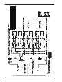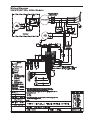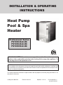
1
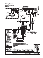
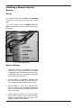
INSTALLATION & OPERATING
INSTRUCTIONS
Heat Pump
Pool & Spa
Heater
Professional Series
PS10353ti-E-HC
PS10354ti-E-HC
PS10355ti-E-HC
R
C
LI S
TED
US
FOR YOUR SAFETY: Do not store or use gasoline or other flammable vapors and
liquids or other combustible materials in the vicinity of this or any other appliance. To
do so may result in an explosion or fire.
NOTE: The instructions in this manual are for the use of qualified individuals specially trained and experienced
in the installation and maintenance of this type of equipment and related system components. Installation and
service personnel are required by some states to be licensed. Persons not qualified shall not attempt to install,
service, or maintain this equipment.
This manual should be maintained in legible condition and kept adjacent to the heat pump pool heater or in a
safe place for future use.
Catalog No. 6000.554A
Effective: 06-28-13
Replaces: 12-21-11
P/N 241460 Rev. 2
92-103778-07-02
Rev. 2 reflects the following:
Changes to: Installation Considerations on pages 6-7, Hurricane Tie Down Requirements diagram on page 8, Table C on
page 14, Wiring diagrams on pages 19-21.
Additions: None.
Deletions: None.
2
Water Chemistry
(Corrosive water voids all warranties)
For your health and the protection of your pool equipment, it is essential that your water be chemically
balanced. The following levels must be used as a guide for balanced water.
Recommended Level(s)
Water Temp. (Deg. F)
pH
Total Alkalinity (PPM)
Calcium Hardness (PPM)
Salt (PPM)
Free Chlorine (PPM)*
Total Dissolved Solids (PPM)
Fiberglass Pools
Fiberglass Spas
Other Pool & Spa Types
7.3 to 7.4
7.3 to 7.4
7.6 to 7.8
68 to 88
89 to 104
68 to 104
120 to 150
120 to 150
150 to 200
200 to 400
4500 MAXIMUM
4500 MAXIMUM
4500 MAXIMUM
3000 MAXIMUM**
3000 MAXIMUM**
3000 MAXIMUM**
200 to 300
2 to 3
2 to 3
80 to 120
2 to 3
*Free Chlorine MUST NOT EXCEED 5 PPM!
** In salt water chlorinated pools, the total TDS can be as high as 6000ppm.
•
•
•
Occasional chemical shock dosing of the pool or spa water should not damage the heater providing
the water is balanced.
Automatic chemical dosing devices and salt chlorinators are usually more efficient in heated water.
Unless controlled, they can lead to excessive chlorine level which can damage your heater.
Further advice should be obtained from your pool or spa builder, accredited pool shop, or chemical
supplier for the correct levels for your water.
3
CONTENTS
Water Chemistry
Warnings
Pay Attention to These Terms
Introduction
Installation Considerations
Electrical Connections
Water Connections
Pressure Drop
Controls
Operating Instructions
To Select Pool or Spa Mode
To Increase the Desired Water
Temperature (Pool or Spa Mode)
To Lower Desired Water Temperature
(Pool or Spa Mode)
To Select Temperature in °C or °F
Heat/Cool Operation
System Start-Up
Seasonal Start-Up or
Annual Check
Summer Shutdown
Freeze Protection
System Drain-Down
Continuous Pump Operation
Maintenance
Air Coil Cleaning
Cabinet Care (optional)
Unplug Condensation Drain Holes
Troubleshooting
Service Call Verification
Power Supply
Water Flow
Time Clock Adjustment
Plumbing Diagrams
Wiring Diagram — 208V/230V
Three-Phase — 60 Hz
Wiring Diagram — 460V
Three-Phase — 60 Hz
Wiring Diagram — 380V
Three-Phase — 60 Hz
Installing a Remote Control
Device
Wiring
Heater Settings
3
5
5
6
6
7
9
9
10
10
10
10
10
10
11
11
11
11
12
4
12
12
12
12
12
12
12
13
13
13
14
15
19
20
21
22
22
22
Warnings
DANGER:
WARNING:
CAUTION:
NOTE:
—
Pay Attention to These Terms
Indicates the presence of immediate hazards which will cause severe personal injury, death
or substantial property damage if ignored.
Indicates the presence of hazards or unsafe practices which could cause severe personal
injury, death or substantial property damage if ignored.
Indicates the presence of hazards or unsafe practices which could cause minor personal
injury or product or property damage if ignored.
Indicates special instructions on installation, operation, or maintenance which are important
but not related to personal injury hazards.
This manual, as well as the pool/spa heat pump pool heater itself, contains ANSI-approved product safety signs
and labels. Please read these signs and labels, as they convey important safety information about hazards that
may be potentially present in and around the heat pump pool heater.
CAUTION: Elevated water temperature can be
hazardous. The U.S. Consumer Product Safety
Commission has these guidelines:
CAUTION: Improper chemical content in a swimming pool or spa can damage the heat pump pool
heater. DO NOT add pool chemicals to the skimmer.
This will damage the heat pump pool heater and
could void the heat pump pool heater warranty.
ALWAYS follow the product manufacturer’s directions when adding any chemicals to your pool.
2. Drinking of alcoholic beverages before or during
spa or hot tub use can cause drowsiness which
could lead to unconsciousness and subsequently
result in drowning.
WARNING: These heat pump pool heaters are
charged with R-410A refrigerant. Ensure that all
service work is done with gauges and equipment
suitable for R-410A.
1. Spa water temperatures should never exceed
104°F (40°C). A temperature of 100°F (38°C) is
considered safe for a healthy adult. Special caution is suggested for young children.
3. Pregnant Women Beware! Soaking in water over
102°F (39°C) can cause fetal damage during the
first three months of pregnancy resulting in the
birth of a brain-damaged or deformed child.
Pregnant women should stick to the 100°F (38°C)
maximum rule.
4. Before entering the spa or hot tub, users should
check the water temperature with an accurate
thermometer; spa or hot tub thermostats may err
in regulating water temperatures by as much as
4°F (2.2°C).
5. Persons with a medical history of heart disease,
circulatory problems, diabetes, or blood pressure
problems should obtain a physician's advice
before using pools or hot tubs.
6. Persons taking medications which induce drowsiness, such as tranquilizers, antihistamines, or
anticoagulants, should not use spas or hot tubs.
5
Introduction
Installation Considerations
WARNING: Do not install the unit within 3 ft of
fossil fuel burning heaters. Air intake along the
sides of this heat pump pool heater could disturb
the combustion process of the unit, and could
cause damage or personal injury.
• Mount the unit on a level, sturdy base, preferably a
concrete slab or blocks. The size of the base should
be at least 3 ft by 3 ft.
• You must install the 4 black rubber sound isolation pads (each 2 inches square) that ship with
the unit. The pads are shipped in a bag with the
unions, gaskets and the I&O manual. Install pads
under the 4 corners of the unit to reduce vibration and sound transmission to the base.
WARNING: This pool/spa heat pump pool heater is
an electromechanical machine that incorporates a
pressurized refrigerant gas in a sealed system.
ONLY trained and qualified service personnel are
authorized to install or service this equipment.
Without proper training and knowledge of such
equipment, any attempt to install or service the unit
could result in serious injury or even death.
This manual contains important information on the
use, maintenance and troubleshooting of your new
heat pump pool heater. This unit must be properly
installed, maintained and operated for optimal performance.
This heat pump pool heater is an extremely efficient,
economical machine designed specifically for swimming pool heating. It is similar in design and operation
to a typical residential air conditioning system. The unit
employs a hermetic motor/compressor operating in a
refrigeration cycle to extract heat from ambient air and
deliver it to the circulating pool water.
CAUTION: The unit’s supporting base must be high
enough to keep it completely free of standing water
at all times.
Situate the heat pump pool heater carefully to minimize installation costs while providing maximum
efficiency of operation, and to allow adequate service
access, as follows:
As with all heat pump pool heaters, compared to other
types of heaters such as gas or oil-fired, this heat
pump pool heater has lower heating capacity on a
BTUH/hr basis. As a result, it will be required to operate longer to accomplish the desired results. It may, at
certain times, operate as much as 24 hours per day.
However, this should not be of concern to the owner,
because the unit is designed to operate continuously.
Even though it may operate continuously for many
hours, it will still heat the pool with greater economy
than other types of fossil fuel heaters.
•
For unrestricted air intake and service access,
position each side of the unit at least 1 ft (30 cm)
from walls, pipes and other obstructions.
WARNING: This unit is designed for outdoor installation; DO NOT install it in an enclosed area such as
a shed or garage.
•
Place a cover or blanket over the pool at night and
other non-use periods. This will keep evaporation, the
cause of main heat loss, to a minimum, and will greatly reduce pool heating costs. During warmer weather,
the cover may be required only at night.
•
•
•
6
Recirculation of cold discharge air back into the
evaporator coil will greatly reduce the unit’s heating capacity and efficiency.
This unit features an ‘up-flow’ discharge for quiet
operation. Air is pulled up through the evaporator
coil and discharged through the top grill. Allow at
least 5 ft (1.5 m) clearance above the unit for unrestricted air discharge. DO NOT install the unit
under a porch or deck. Refer to Fig. 1.
To minimize water piping, locate the unit as close
as possible to the existing pool pump and filter.
If the location of the heat pump pool heater is
below the water line of the pool, the water pressure switch might need to be adjusted or an
external water flow switch might be needed.
60”
MIN
3 FT
MIN
GAS
HEATER
•
•
•
•
•
AIR FLOW OUT
12”
MIN
AIR
FLOW
IN
AIR
FLOW
IN
Fig. 1: Installation Clearances
Irrigation water should be directed away from the
heat pump pool heater-water spray can damage
the heat pump pool heater.
All wiring must be in accordance with the National
Electrical Code, NFPA No. 70, latest edition, and all
applicable state and local codes. Wiring diagrams are
located on pages 19 through 21.
Rain water run offs- the heat pump pool heater
can withstand normal rain. Install rain gutters to
prevent direct steams of rain water to the heat
pump pool heater.
It is important to keep the area next to the heat
pump pool heater clear of shrubs, bushes and
chemicals containers. They could prevent air from
circulating fully through the heat pump pool heater,
and will affect the operation of the heat pump pool
heater or damage the heat pump pool heater.
•
•
When installed in areas where freezing temperatures can be encountered, drain the water circuit
to prevent possible freeze-up damage. See the
Freeze Protection Section.
•
For high wind installation requirements, refer to
the diagram on page 8.
Electrical Connections
NOTE: Refer to the National Electrical Code, Article
680, for general requirements for swimming pools
and equipment, and to Article 440 for special considerations necessary for circuits supplying hermetic
refrigeration motor/compressors.
Locate the equipment disconnect means within 3
feet of the heater’s electrical enclosure, or as
close to the heater as possible. Always satisfy
applicable codes and standards.
In sizing power wiring, be especially aware of upsizing requirements necessary due to wiring
distances. Always satisfy applicable codes and
standards.
Electrical installation should be done by a licensed
electrician only.
This unit is pre-wired to work with external control systems, heat-on-demand options and other external time
clock overrides. Refer to the external control system’s
instructions, and page 22 of this manual, for installation information.
Refer to the unit rating plate below the control panel for
precise power requirements for your unit, and for
ampacity and over-current protection requirements.
7
8
SEE HIGH WIND LOAD
RESTRAINT DETAIL 1
COVERED UNIT
HEIGHT BETWEEN
37-1/2” - 49-3/4”
NOT INCLUDING
ISOLATOR PADS
GREATER THAN OR EQUAL TO 4” THICK SOLID CONCRETE 3000 P. S. I. OR GREATER LOAD RATING
PAD LENGTH GREATER THAN OR EQUAL TO UNIT LENGTH +6”
PAD WIDTH GREATER THAN OR EQUAL TO UNIT WIDTH +6”
PAD SPECIFICATION:
THIS DRAWING USED AS A GRAPHICAL REPRESENTATION ONLY AND IT
MAY NOT APPEAR EXACTLY LIKE YOUR SPECIFIC UNIT.
2-1/2” MIN.
SPACING TYP.
27” MIN
32” MAX
RESTRAINT
SPACING
(4) VIBRATION ISOLATION
PADS TYP. EA. CORNER
UNIT
(2) 1/4” CONCRETE SCREWS
LENGTH TO PENETRATE
2-3/8” MINIMUM.
HIGH WIND LOAD RESTRAINT DETAIL 1
CONCRETE PAD
(SEE PAD SPECS.)
CL
MINIMUM 18 GA. X 5” WIDE GALV. STEEL STRAP
(G90) OR EQUIVALENT (MIN. QTY. OF 4 STRAPS)
WITH (3) 1/2” LONG #12 SELF DRILLING SCREWS
EACH STRAP (MIN. 1000 HR. COATING)
186 MPH, 3 SEC. GUST IN ACCORDANCE WITH:
ASCE 7-2010 CHAPTER 30 WIND LOADS - COMPONENTS AND CLADDING
FLORIDA BUILDING CODE 2010 - SECTION 1609 WIND LOADS
FLORIDA BUILDING CODE 2010 - SECTION 1620 HIGH VELOCITY HURRICANE ZONES - WIND LOADS
Model No.
VAC - Phase - Hz
Minimum Circuit
Ampacity (A)
Maximum Breaker
Size (A)
10353
208/230 - 3 - 60
42.0
70
10354
460 - 3 - 60
26.0
40
10355
380 - 3 - 60
29.0
45
Table A: Typical System Electrical Power Requirements
Water Connections
CAUTION: The heat pump pool heater inlet and
outlet connections are NOT interchangeable. They
must be connected as instructed below.
WATER IN
1. Connect the heat pump pool heater in the return
water line between the filter and the pool/spa. See
the Plumbing Diagrams beginning on page 15.
Fig. 2: Water Connections
2. Connect the filter outlet to the fitting marked
WATER IN at the bottom front of the unit.
4. In cold weather (freeze zone) areas, shutoff valves
(ball or gate type) must be installed at the unit inlet
and outlet to facilitate service and cold weather
drain-down.
3. Connect the fitting marked WATER OUT to the
return piping to the pool/spa. Unit inlet/outlet connection fittings are 2-inch PVC unions.
5. Operate the pump and check the system for leaks.
Pressure Drop
Water connections from the unit to the main return
line can be PVC pipe or flexible pipe approved for
the purpose and, in either case, should be at least
equal in size to the main pool/spa circulation piping.
Flow
(gpm)
10353HC
40
10
30
50
10
WATER OUT
For system pressure drop information, refer to Table B
below.
Pressure Drop (psi)
10354HC
10355HC
10
10
10
11
11
10
11
60
12
12
12
80
14
14
14
70
13
13
13
Note: Multiply the pressure drop in psi by 2.3067 to yield the pressure drop in Ft. H2O Head (TDH).
Table B: Pressure Drop Across Heat Pump Pool Heater
9
Operating Instructions
WARNING: Install a check valve and/or a Hartford
loop AFTER the heat pump pool heater and
BEFORE any chlorinating devices. Install any automatic chemical feeders AFTER the heat pump pool
heater. Improper installation of any type of automatic chemical feeders can result in serious
damage to, or premature failure of, the heat
pump pool heater and will void the heat pump
pool heater warranty.
The electronic board has the capability of memorizing
two different programmed temperature settings as follows (refer to Fig. 5):
•
•
Controls
For a pool, maximum 95°F (35°C)
For a spa, maximum 104°F (40°C)
To Select Pool or Spa Mode
Your heat pump pool heater incorporates digital safety
controls and indicators to ensure its safe, reliable
operation.
To have access to either one of these programs, press
the SET key until you see P _S and by pressing the
UP or DOWN key you can switch to POL or SPA.
Water Pressure Switch: Prevents operation when the
pump is OFF. The unit requires 5 psi minimum pressure.
To Increase the Desired Water
Temperature (Pool or Spa Mode)
Push the SET key until you see POL or SPA. The programmed temperature will be displayed. Press the UP
arrow to increase the temperature setting one degree
at a time.
Digital Water Temperature Control: The pool water
temperature is controlled by the heat pump pool
heater’s digital control system, which gives you the
option of two settings: one for the desired spa temperature and the other for the desired pool temperature.
Additionally, as mentioned earlier, the unit is compatible with most ‘2-wire’ and ‘3-wire’ control/automation
systems.
To Lower the Desired Water
Temperature (Pool or Spa Mode)
Push the SET key until you see POL or SPA. The programmed temperature will be displayed. Press the
DOWN arrow to decrease the temperature setting one
degree at a time.
Once the control has been programmed to the desired
pool water temperature, the programmed temperature
will be displayed for approximately 5 seconds. Then
the digital display will display the actual pool water
temperature.
To make the Board a Pool ONLY Board, call 800260-2758 for instructions.
To Select Temperature in °C or °F
Fig. 5: Digital Water Temperature Control
Defrost Sensor: Prevents unit operation if ambient air
temperature falls below a predetermined safe minimum (approximately 42°–48°F (5.5°-8.8°C) based on
humidity). The compressor will shut OFF but the fan
will continue to run.
Delay Timer: Prevents compressor from short cycling,
which could damage or destroy the hermetic
motor/compressor. Upon water temperature control
satisfaction, or other circuit interruptions, this solid
state device will prevent compressor restart for
approximately 5 minutes.
Press the SET key until you see F _C. By pressing the
UP or DOWN key you can switch to °F or °C. Once the
temperature display mode has been programmed it
will be displayed for approximately 5 seconds, then
the digital display will return to the actual pool water
temperature in the mode that you have chosen.
10
Heat/Cool Operation
Seasonal Start-Up or Annual
Check
The Raypak Professional models come standard with
heat/cool operation. The heat/cool model is designed
to both heat and cool the pool. To select heat or cool
mode, push the SET key until H/C is displayed. Press
the DOWN arrow key to select heating (hea), or the
UP arrow key to select cooling (col). Set the desired
setpoint temperature as described earlier in this manual.
NOTE: At the beginning of the heating season, or
whenever the pool water temperature is to be raised
several degrees, the pool pump and heat pump pool
heater may need to operate continuously for several
days. During summer months, only a few hours per
day may be necessary, or none at all.
NOTE: Once the control has been programmed to
the desired pool water temperature, the programmed temperature will be displayed for
approximately 5 seconds. The digital display will
then show the actual pool water temperature.
1. Remove leaves, pine needles, etc., from the evaporator coil. Clean the coil by gently applying a mild
solution of household liquid soap and water.
2. Gently rinse the coil with water; DO NOT use high
pressure.
NOTE: Remove the pool/spa blanket and turn on
any fountains, sprays or other water features to
speed cooling.
3. Backwash or otherwise clean the pool filter. If necessary, clean the skimmer basket and pump
strainer.
When the unit has been operating in the heating mode
for a few minutes, the discharge air temperature
should be 8°–10°F (4.5°–5.6°C) cooler than the air
entering the unit.
NOTE: If the pool pump and heat pump pool heater
shut OFF before the water temperature is raised to
the desired level, you must lengthen the running time
of both. To do this, reset the time clock dial for the
longer running time, or manually operate the pump
with the timer override switch. Since the heat pump
pool heater capacity and efficiency are both greater
at higher ambient air temperatures, run time should
be set to take advantage of all daylight hours, when
the air is generally warmer.
When the unit has been operating in the cooling mode
for a few minutes, the discharge air temperature
should be 8°–10°F (4.5°–5.6°C) warmer than the air
entering the unit.
NOTE: Heating is more efficient during warmer daylight hours and cooling is more efficient during cooler
night time hours.
4. Set the valves to ensure proper water flow through
the unit.
1. Verify that the Digital Board is displaying a temperature and the pool pump is running and water is
circulating properly.
If you do not plan to use the heat pump pool heater
during the summer months, secure and protect it as
follows:
System Start-Up
Summer Shutdown
1. Turn the unit circuit breaker or disconnect switch to
OFF.
2. Verify that the Board is programmed so that the
desired temperature of the Pool and Spa is higher
than the displayed current water temperature.
2. Leave the valves set the way they are unless additional circulation is required. DO NOT stop all flow
through the heat pump pool heater.
3. Allow the heat pump pool heater to operate for a
few minutes to stabilize operating pressures and to
allow various component temperatures to normalize.
4. Verify that the discharge air temperature is approximately 8°–10°F (4.5°–5.6°C) cooler than the air
entering the unit. If not, see the Troubleshooting
Section.
3. IMPORTANT: Remember to reset the valves
before the next heating season, or the unit will not
operate properly.
11
Freeze Protection
Cabinet Care (optional)
If the unit is installed in a location subject to freezing
conditions, it is important to protect the water circuit
from freezing, just as should be done for the pump and
filter.
The stainless steel cabinet is designed for harsh outdoor use and requires little care. However, you can
clean it if you wish.
1. Turn the unit circuit breaker or disconnect switch
to OFF.
Wash the cabinet with soap and water.
WARNING: Shut OFF electricity to the unit before
cleaning.
System Drain-Down
Unplug Condensation Drain Holes
2. With the pool pump OFF, close the external shutoff valves and loosen the inlet and outlet water
unions to allow water to drain. Use a Wet/Dry Vac
or air pressure to remove excess water.
The unit extracts humidity from the air as it passes
through the coil, similar to the way a cold drink outside
“sweats” on a hot day. This condensation drains from
the bottom of the unit.
3. Loosely re-attach the unions.
1. Routinely check to be sure the condensation drain
holes in the base of the unit are not plugged with
dirt or debris.
4. Cover the unit with a waterproof cover.
Continuous Pump Operation
2. If condensation becomes a problem, optional drain
pans are available from your heat pump pool
heater distributor or pool dealer.
It is also possible in some areas to prevent unit freeze
damage by operating the pump continuously during
freezing weather. However, this results in significantly
higher pump operating costs. Further, if a sustained
power failure occurs, the unit MUST be drained anyway, or freeze damage could result.
Troubleshooting
If your unit does not operate, or simply does not heat
your pool water, Fault Codes on the front control
panel, can provide valuable clues as to what is wrong,
and may even indicate precisely what the problem is.
Always observe these codes before calling a service
representative. By reporting on the telephone the Fault
Codes that are showing, the service rep may be able
to solve the problem without the expense of a service
call.
Maintenance
NOTE: The heat pump pool heater MANUFACTURER IS NOT RESPONSIBLE for maintenance
adjustments.
The following maintenance procedures are designed
to keep your unit operating at a high level of reliability.
Maintenance must be performed on a periodic
basis to maintain warranty coverage and prevent
system failures and performance degradation.
A. UNIT IS RUNNING, BUT NOT HEATING
•
Air Coil Cleaning
Efficient operation depends on free circulation of air
through the thin and tightly-spaced fins of the evaporator coil(s). The evaporator must be cleaned
whenever it has a buildup of dirt or debris.
•
•
CAUTION: To clean the fins, spray gently with a
garden hose. DO NOT pressure wash. Doing so
will bend the fins and can void the warranty.
12
Is water flow through the unit adequate? Check
the unit for obstructions, such as a clogged filter
pump strainer, a dirty filter, or valves not positioned correctly. Check the operation of the flow
switch.
Is the ejected air from the unit 8°–10°F
(4.5°–5.6°C) cooler than incoming air? If so, the
unit is extracting heat from the air and transferring
it to the pool.
Is water condensing on the evaporator and internal copper pipes? This is also evidence of heat
removal from the air. When the air is cool with low
humidity, condensation may not be evident.
•
•
How long has the unit been operating? During initial pool heating in cold weather, it may require a
week to elevate the water temperature to a comfortable level. Normally, it takes about 4 days.
NOTE: The heat pump pool heater will not run when
the Remote position is selected on the Pool/Spa
selector switch and there is no remote control system attached.
How many hours per day is the unit operating?
Remember that the heat pump pool heater only
operates while the pool pump is running. Set the
time clock to permit 24 hour per day operation. After
the desired temperature is reached, return the unit to
normal operation of 8–10 hours per day.
C. CONDENSATION SEEMS EXCESSIVE
Heat pump pool heaters can produce a large amount
of condensation (water) during operation. If you suspect that the unit is leaking:
NOTE: If the pool pump and heat pump pool heater
shut OFF before the water temperature is raised to
the desired level, you must lengthen the running time
of both. To do this, reset the time clock dial for the
longer running time, or manually operate the pump
with the timer override switch. Since the unit capacity and efficiency are both greater at higher ambient
air temperatures, run time should be set to take
advantage of all daylight hours, when the air is generally warmer.
•
•
•
a. Use a pool chemistry test kit to confirm there is no
chlorine in the condensation. Or,
b. Shut the unit OFF and leave the filter pump running to see if the water stops dripping. If the water
stops dripping, the unit is not leaking.
Service Call Verification
Is airflow through the unit being obstructed?
Restrictions such as shrubbery, tall grass, dirty
coils, or any other obstruction to airflow will reduce
performance.
NOTE: The Raypak Service number is 800-260-2758.
For units in Canada, call 800-268-6966.
Before you make a service call, first determine if the
problem is:
Is the pool blanket/cover being used?
Unblanketed pools can lose up to 10 degrees per
night compared to 4 degrees or fewer when a
blanket is used. Without a blanket, the total heat
gained during the day can be lost overnight.
•
•
Are rapid heat losses occurring in some other way,
such as high wind, spillage, rainfall, flow through
solar panels at night, or a high water table?
•
•
Warranty Service
Unit operation (power supply, water flow, or time
clock adjustment)
NOTE: The MANUFACTURER IS NOT RESPONSIBLE for these adjustments.
Power Supply
B. UNIT IS NOT RUNNING
•
Is the Heat Light ON? If not, then the thermostat
setting is not higher than the temperature of the
water. Raise the thermostat setting.
•
Is the temperature display ON? If not, the circuit
breaker may be shut OFF or tripped. Reset the
breaker by switching it OFF, and then back ON.
Verify that the breaker is set and operating
properly before calling for service.
•
Is the thermostat setting and the Pool/Spa setting
correct? Verify that the temperature has been
properly set on the thermostat, and that it is higher than the current water temperature.
Verify that all circuit breakers are reset and working properly.
If the temperature display still does not light, contact the installing dealer, since it may be a power
problem requiring an electrician.
Water Flow
•
Have you waited approximately 5 minutes for the
time delay? After the unit has been running and
then shut OFF for any reason, there is a delay
before operation can begin again.
•
13
Verify that the pool filter is clean to provide good
flow.
Verify that valves are properly positioned to allow
adequate water flow through the unit.
Time Clock Adjustment
Verify that the time clock is set to permit the unit to run long enough to heat properly.
Fault Code
OFF
LP
LP3
HP
HP6
PSd
Meaning of Code
The desired programmed temperature point is lower than 50°F (10°C).
There is a shortage of refrigerant gas in the unit or a faulty low pressure control, or the
ambient air is too cold.
The unit has encountered 3 LP faults within the same call for heat and shut down the unit
for protection. If this occurs, you should call for service.
There is low water flow in the unit or a faulty high pressure control. Check water
flow/backwash.
The unit has encountered 6 HP faults within the same call for heat and shut down the unit
for protection. If this occurs, you should call for service.
The water temperature sensor is open or may be defective.
dSd
The suction line temperature sensor is open or may be defective.
FLO
Possible causes:
• The filter is in backwash position.
• The filter pump is stopped.
• The filter is dirty.
• Shortage of water to pool pump.
• Water flow switch may be broken.
FL3
FS
FS5
COL
The unit has encountered 3 FLO faults within the same call for heat and shut down the
unit for protection. If this occurs, you should call for service.
Unit is in the defrosting cycle.
The unit has gone into the defrosting cycle 5 times within the same call for heat and shut
down the unit for protection.
The unit is in the cooling mode.
HEA
The unit is in the heating mode.
HOT
The unit has gone into a fault mode during cooling.
--
Keypad is pressing down on both buttons. Replace keypad.
Table C: Control Board Fault Codes
14
WATER IN
(FROM POOL OR
SPA)
FILTER
CHECK
VALVE
CHEMICAL
INTRODUCTION
WATER OUT
(TO POOL OR
SPA)
Plumbing Diagrams
Fig. 6: For systems with pumps of less than 2 HP (under 80 gpm), no external
bypass is required. Connections are 2-inch unions. Plumb the heat
pump pool heater AFTER the filter and BEFORE any chlorinators.
15
WATER OUT
(TO POOL OR
SPA)
WATER IN
(FROM POOL OR
SPA)
FILTER
CHECK
VALVE
CHEMICAL
INTRODUCTION
Fig. 7: For systems with pumps of 2 HP or greater (over 80 gpm), an external
bypass is required. Adjust the bypass valve to divert a minimum of 40
gpm through the heat pump pool heater. Connections are 2-inch unions. Plumb the
heat pump pool heater AFTER the filter and BEFORE any chlorinators.
16
Fig. 8: Pool Piping for Heat Pump Pool Heater and Gas Pool Heater
17
Fig. 9: Pool Piping for Heat Pump Pool Heaters, Multiple, Primary/Secondary
18
2 UNITS
BRANCH
MAIN
15 GPM
2"
2"
30
2"
2"
45
2"
2"
60
2"
2-1/2"
80
2"
3"
*Sizing based on 10 ft/sec flow rates
MINIMUM PIPE SIZES
3-4 UNITS
BRANCH
MAIN
15 GPM
2"
2"
30
2"
2-1/2"
45
2"
3"
60
2"
3"
80
2"
4"
15 GPM
30
45
60
80
5-6 UNITS
BRANCH
2"
2"
2"
2"
2"
MAIN
2"
3"
4"
4"
5"
Wiring Diagram
208V/230V 3Ph, 60Hz Models
19
Wiring Diagram
460V 3Ph, 60 Hz
Models
20
Wiring Diagram
380V 3Ph, 60 Hz
Models
21
Installing a Remote Control
Device
Wiring
For a 2-wire control, use the TOTAL and COMMON
connections on the heat pump pool heater wiring
block.
For a 3-wire control, use the COMMON, SPA and
POOL connections on the heat pump pool heater
wiring block.
Fig. 11: Heater Wiring Block
Heater Settings
1. Make sure the heater is disabled on the remote
control device. Then, push the SET key until POL
is displayed. Push the DOWN arrow key until OFF
is displayed. Wait until a temperature is displayed
before beginning the next step.
2. Push the SET key until SPA is displayed, then
push the UP arrow to 104°F. Wait until a temperature is displayed before beginning the next step.
3. Push the SET key until P_S is displayed, then
push the DOWN arrow until POL is displayed.
Wait until a temperature is displayed before beginning the next step.
4. Finally, enable the heater on the remote control
device. When there is a call for heat, the heater
display will show SPA. When the heater is disabled, the display will show POL.
22
23
Raypak, Inc., 2151 Eastman Avenue, Oxnard, CA 93030 (805) 278-5300 Fax (805) 278-5468
Heat Pump Service 1-800-260-2758
Litho in U.S.A.
24