1
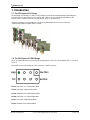
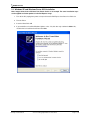
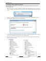
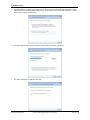
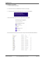
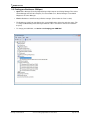
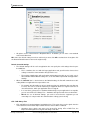
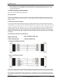
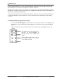
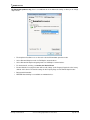
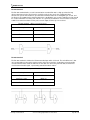
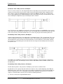
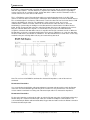
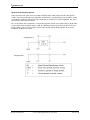
Print Date:24/04/2013
PX-101, PX-146, PX-157, PX-235,
PX-246, PX-260, PX-310, PX-313,
PX-320, PX-324, PX-335, PX-346,
PX-368, PX-376, PX-387, PX-420,
PX-431, PX-475, PX-701, PX-801,
PX-803, PX-805, PX-809, PX-812,
PX-846, PX-823
Product Manual
Brainboxes Limited, 18 Hurricane Drive, Liverpool International Business Park, Speke, Liverpool, Merseyside, L24 8RL
Tel: +44 (0)151 220 2500 Fax: +44 (0)151 252 0446 Web: www.brainboxes.com Email: [email protected]
Contents
1. Introduction .................................................................................................................................................... 4
1.1. The PCI Express PX- Range .................................................................................................................. 4
1.2. The PCI Express PX POS Range ........................................................................................................... 4
1.3. Supported Operating Systems ................................................................................................................ 5
2. Installation Instructions .................................................................................................................................. 6
2.1. Windows XP and Windows Server 2003 installation .............................................................................. 7
2.2. Windows Vista & Server 2008 64 & 32 bit installation .......................................................................... 10
2.3. Windows 7/Server 2008 R2 installation ................................................................................................ 13
2.4. Windows 8 installation .......................................................................................................................... 16
2.5. Finding your Brainboxes COM port....................................................................................................... 19
2.6. Changing your COM label ..................................................................................................................... 20
2.7. Port Settings.......................................................................................................................................... 21
2.8. RS-232 Settings and Information .......................................................................................................... 23
2.9. RS-422/485 Settings and Information ................................................................................................... 24
2.10. UART Settings .................................................................................................................................... 32
3. Uninstallation – Windows Server 2008/Vista/Server 2003/XP .................................................................... 34
4. Boost.PCIe Driver Upgrade / Rollback ........................................................................................................ 37
4.1. Upgrading the Boost.PCIe Driver.......................................................................................................... 37
5. Troubleshooting and Testing ....................................................................................................................... 38
5.1. Installation problems ............................................................................................................................. 38
5.2. Communication Problems ..................................................................................................................... 38
5.3. Testing your Serial COM port ............................................................................................................... 39
6. Lifetime Warranty and Support .................................................................................................................... 40
7. Technical Specifications .............................................................................................................................. 41
7.1. Supported Serial Settings ..................................................................................................................... 41
7.2. Device Pin-out ....................................................................................................................................... 41
7.3. RS-422/485 bias/terminating resistors - applicable to RS422/485 products only ................................ 43
7.4. Company Accreditation ......................................................................................................................... 43
7.5. Europe – EU Declaration of Conformity ................................................................................................ 44
PX Range Product Manual
Version 2.3 © Copyright Brainboxes Limited 2013
Page 2 of 45
7.6. WEEE Directive (Waste Electrical and Electronic Equipment) ............................................................. 44
7.7. RoHS Compliance................................................................................................................................. 44
8. Copyright ..................................................................................................................................................... 45
9. Version History ............................................................................................................................................ 45
PX Range Product Manual
Version 2.3 © Copyright Brainboxes Limited 2013
Page 3 of 45
1. Introduction
1.1. The PCI Express PX- Range
The PX-Range are PCI Express (PCIe) cards providing several RS-232 and RS-422/485 9-pin COM ports
(see datasheets for alternatives) to any computer with a PCIe Lane. The advantage of Brainboxes PCI
Express cards is that they can fit into any standard 1x, 4x, 8x or 16x PCIe Lane.
Using the PCI Express card’s COM ports, all supporting 921,600 Baud, makes fast and effective
communication between multiple devices simple.
1.2. The PCI Express PX POS Range
These are powered products for POS or powered applications. They offer 12V or GND on Pin 1 & 12V or 5V
on Pin 9.
The power is taken from the PC via a Disk Connector or SATA connector.
PX-801 Low Profile 1+1 x RS232 POS SATA
PX-803 Low Profile 1xRS232 POS SATA
PX-846 Standard Profile 1xRS232 POS SATA
PX-809 Low Profile 1+1 x RS232 POS DISK
PX-812 Low Profile 1xRS232 POS DISK
PX-823 Standard Profile 1xRS232 DISK
PX Range Product Manual
Version 2.3 © Copyright Brainboxes Limited 2013
Page 4 of 45
1.3. Supported Operating Systems
The PCI Express PX Range can be used with the following Microsoft Operating Systems with the supplied
Boost.PCIe drivers;
Brainboxes PCI Express Drivers have undergone Microsoft testing with the PX RS-232 and RS-422/485
family. Upon passing these tests, the drivers were signed by Microsoft, as an indication of their quality and
stability.
PX Range Product Manual
Version 2.3 © Copyright Brainboxes Limited 2013
Page 5 of 45
2. Installation Instructions
PLEASE READ CAREFULLY
•
For RS-232 Cards, there are two Installation steps to installing the Boost.PCIe driver:
1. CARD driver
2. PORT driver
•
For RS-422/485 Cards, there are three Installation steps to installing the Boost.PCIe driver:
1. CARD driver
2. PORT driver
3. BASE SYSTEM DEVICE driver. This is the RS-422/485 Controller
•
Each step will take you through a full installation using the Found New Hardware wizard.
•
Once the Card is installed, the Operating System will detect the COM Port. All you will need to do to
install the COM Port is to run through the same installation steps as the Card. This also applies to
the RS-422/485 Controller
•
Follow the Operating System specific instructions below to start the installation procedure.
If you have any issues with installation, please follow the steps in Section 4: Uninstallation, then attempt to
install again. If you still have issues, see Section 6: Troubleshooting and Testing
PX Range Product Manual
Version 2.3 © Copyright Brainboxes Limited 2013
Page 6 of 45
2.1. Windows XP and Windows Server 2003 installation
Note: Images below show a PX-260 4 Port RS-232 device as an example. The same installation steps
can be applied to all other products in the PCI Express range.
1. Turn off the PC (unplug from power socket) and insert the PCI Express Card into a free PCIe slot.
2. Turn the PC on.
3. Insert the Boost.PCIe CD
4. If you would like to install via Windows Update, select “Yes, this time only”. Otherwise Select ‘No,
not this time’ to install from the CD and click next.
PX Range Product Manual
Version 2.3 © Copyright Brainboxes Limited 2013
Page 7 of 45
5. The Found New Hardware Wizard will then ask you to locate the software drivers.
If you have chosen to search Windows Update, select “Install the software automatically
(Recommended)”. This will take you to Step 7. If you wish to install from the Boost.PCIe CD,
select “Install from a list or specific location (Advanced)” and click next to point to the CD
drive.
6. Select to ‘Search for the best driver in these locations’ and then ‘Search removable media’, as
shown below. Click Next
PX Range Product Manual
Version 2.3 © Copyright Brainboxes Limited 2013
Page 8 of 45
7. The Installer will copy across all the drivers and associated registry files. Click Finish when
complete.
8. If you are installing a multiport card, you will need to install each port manually following steps 4-7
when prompted for each port on your card.
9. If you are installing a 422/485 card, you will also need to install the “Base System Device”. This is
the 422/485 Controller for your card. Follow steps 4-7 again when prompted.
10. Once installed, you can check the COM Number of the Port, by opening Device Manager (See
Section 3.1: Finding your Brainboxes COM port). If you need to change the COM port number,
see Section 3.2 Changing Your COM Label.
PX Range Product Manual
Version 2.3 © Copyright Brainboxes Limited 2013
Page 9 of 45
2.2. Windows Vista & Server 2008 64 & 32 bit installation
Note: Images below show a PX-260 4 Port RS-232 device as an example. The same installation steps
can be applied to all other products in the PX PCI Express range.
1. Turn off the PC (unplug from power socket) and insert the PCI Express Card into a free PCIe slot.
2. Turn the PC on.
3. Insert the Boost.PCIe CD
4. The Found New Hardware Wizard will come up. If your computer is set to check Windows Update
Automatically for a driver, then it could take longer for this screen to pop up.
5. Select ‘Locate and install driver software’.
6. NB Vista will enter the Security Check to ensure that you have initiated the installation (and not
some malicious program). Click Continue
PX Range Product Manual
Version 2.3 © Copyright Brainboxes Limited 2013
Page 10 of 45
7. If you would like to install via Windows Update, select “Yes, this time only”. This will take you to
Step 9. Otherwise select ‘Don’t search online’ to install from the CD.
8. The Found New Hardware Wizard will then ask you to locate the software drivers. Ensure that the
CD is in the drive and click Next
PX Range Product Manual
Version 2.3 © Copyright Brainboxes Limited 2013
Page 11 of 45
9. Once the driver has been installed, click Close.
•
If you are installing a multiport card, the Operating System will install each subsequent Serial Port
automatically.
•
If you are installing a 422/485 card, you will also need to install the “Base System Device”. This is
the 422/485 Controller for your card. Follow steps 4-9 again when prompted.
•
Once installed, you can check the COM Number of the Port, by opening Device Manager (See
Section 3.1: Finding your Brainboxes COM port). If you need to change the COM port number,
see Section 3.2 Changing Your COM Label.
PX Range Product Manual
Version 2.3 © Copyright Brainboxes Limited 2013
Page 12 of 45
2.3. Windows 7/Server 2008 R2 installation
Note: The following installation instructions use a PX-346, but the installation instructions are the
same for any PX card.
1. When you boot up your computer on Windows 7, Windows update will automatically search for the latest
drivers. If you have a connection to the internet, the drivers will be installed and the device will be ready
to use.
2. If there is no connection to the internet or the drivers can’t be found, a message will appear to tell you
that device driver software was not successfully installed.
3. To install the drivers Device manager will need to be opened. To open device manager go to the control
panel, system, hardware tab, then click on the device manager button.
4. Once this is open you will see the yellow ! icon in the other devices node. Right click on the device and
click on update driver software.
PX Range Product Manual
Version 2.3 © Copyright Brainboxes Limited 2013
Page 13 of 45
5. If your Brainboxes card came with a CD insert it now and select to search automatically and the driver
software will be found and installed. Skip to step If not and you have a folder with the drivers, select to
browse your computer for the drivers.
6. Select the folder which contains the drivers that you want to install for your device.
7. The drivers will then be installed for the card.
PX Range Product Manual
Version 2.3 © Copyright Brainboxes Limited 2013
Page 14 of 45
8. You will then need to install the Base System Device (RS-422/485 devices only) and then install all of
the Serial ports using the same steps as above.
9. Once you have installed one of the ports you can scan for hardware changes and the other Serial Ports
will be installed automatically.
PX Range Product Manual
Version 2.3 © Copyright Brainboxes Limited 2013
Page 15 of 45
2.4. Windows 8 installation
1. Insert the PX CD in to your laptop.
2. Insert the PX card in to an available ExpressCard slot on your laptop.
3. You will now see the below window appear. Click on it and a menu will appear.
4. Now select the ‘Open folder to view files’ option from the below window:
5. Go to the bottom of the list of files and select the setup.exe file. This file will install the PX drivers.
PX Range Product Manual
Version 2.3 © Copyright Brainboxes Limited 2013
Page 16 of 45
6. Now that you have selected the setup.exe file, you will now see a window as shown below, click Next.
7. When the drivers are installing, the window will look like the one below.
8. When the drivers have been installed, you will then see a similar window as shown.
PX Range Product Manual
Version 2.3 © Copyright Brainboxes Limited 2013
Page 17 of 45
9. When the drivers have installed, Device Manager will now look like the below image. If there are any
yellow exclamation marks over the Brainboxes products, please right click the device and then update
the driver pointing to the files on the CD-ROM.
PX Range Product Manual
Version 2.3 © Copyright Brainboxes Limited 2013
Page 18 of 45
2.5. Finding your Brainboxes COM port.
•
Open Device Manager (Found by Right Clicking on My Computer and clicking Manage. Then Select
Device Manager from the left hand pane.) For Server 2008 users, Device Manager is found within
Diagnostics in Server Manager.
•
Find the Brainboxes Serial Port entry in Device manager. (Found under the ‘Ports’ section)
•
The Brainboxes Serial Port entry displays the current COM number in brackets after the name. (This
is usually COM3 following install, but may be different if other serial devices have been installed in
the past)
•
To change your COM label, see Section 3.2: Changing your COM label
PX Range Product Manual
Version 2.3 © Copyright Brainboxes Limited 2013
Page 19 of 45
2.6. Changing your COM label
•
If you need to change the COM label, Double click on the Port entry in Device Manager
•
Click on the ‘Port Settings’ tab and click Advanced
•
A new COM Port label can be selected from the “COM Port Number” dropdown menu.
PX Range Product Manual
Version 2.3 © Copyright Brainboxes Limited 2013
Page 20 of 45
•
If the COM Port number is labelled “in use”, it is either currently used by a COM Port present on the
system, or is reserved for a device which is not currently present. It is possible to select this COM
number and force the change, if you are sure it is not required by any other device.
2.7. Port Settings
The Port Settings allow you to set Default or Override Settings for the serial communication and how to deal
with incoming hardware handshaking events.
•
To open ‘Port Settings’, open device manager and double click on the Brainboxes COM Port Entry
under the ‘Ports’ section
•
Then Click on the ‘Port Settings’ tab.
PX Range Product Manual
Version 2.3 © Copyright Brainboxes Limited 2013
Page 21 of 45
•
All options can be selected from the Dropdown Menus. In addition, you can enter a non-standard
value into the Baud rate
NB – Once the desired settings have been achieved, you must click OK to activate them. At anytime click
the ‘Restore Default’ button to return to the original setup.
Default / Override Settings
•
•
The “Default Settings” will be set if an application does not specify the serial settings when it opens
the COM Port.
o
This is sometimes the case with old Legacy applications and you will need to choose these
settings to match the communications that you wish to use.
o
The majority of Applications will specify what Serial Settings they wish to use. In this case, it
will not matter what the Default settings are, as the Port will be opened with the Application’s
Settings.
When the ‘Override’ box is checked next to the Default Setting, the Port will communicate at this
setting whether an application has requested it or not.
o
For example, this will enable you to force baud rates that your application does not allow you
to select. This can be useful for interfacing to equipment which uses higher baud rates or
unusual baud rates, which your application does not support.
o
In a case where you want to use hardware handshaking, but your application is not capable,
you can select RTS / CTS Always True – Hardware state ignored and choose to Override it.
o
NB with the use of Override Settings, you need to ensure that the equipment you are
connecting to is setup to match the communications settings you are forcing.
CTS / DSR Always True
•
CTS and DSR are incoming hardware handshaking lines. This means they receive signals from the
connected device which tell the ExpressCard when it is and isn’t OK to send data.
o
Sometimes these signals may want to be ignored. By forcing CTS or DSR True, the
ExpressCard will ignore those signals and always send data.
PX Range Product Manual
Version 2.3 © Copyright Brainboxes Limited 2013
Page 22 of 45
These settings are especially helpful when CTS and DSR are not physically connected (such as in a 3
wire setup) and it is not acceptable for the data flow to stop and start due to arbitrary variances on the
unconnected signal lines.
2.8. RS-232 Settings and Information
Note - this section is for RS-232 products only.
RS-232 Standard
The RS-232 standard was introduced in 1962, it is now widely established. RS-232 is a slow speed, short
distance, single ended transmission system (i.e. only one wire per signal). Typical RS-232 maximum cable
length is 50 feet.
9 Pin D Serial Port RS-232 Cables
To connect to the RS-232 Serial Port you will need a cable terminating in a 9 way female D connector. It is
sound practice to use cables with screws fitted that will allow you to fasten the cable securely to the PC card.
In general, you will need to make up a "cross-over" cable to correctly interface the PC to the RS-232 port of
another computer or device. Provided you have the pin outs and handshake requirements of both sides of
your RS-232 connection, the cross over cable becomes a matter of common sense. The cross-over cable is
simply to ensure that the right signals going out of one RS-232 port go into the appropriate lines of the other
RS-232 port.
Pin D Serial Port Connection To Another PC
Suppose we want to connect the Brainboxes Serial Port to the serial port of another PC. Connect the earth
lines. Line 5 of Serial Port 2 to lines 1 & 7 of the other PC. This gives the two devices a common earth level.
Connect the Transmit and Receive lines together. Line 3, TXD, Port 2 goes to line 3, RXD, of the other PC.
Line 2, RXD, Port 2 goes to line 2, TXD, of the other PC. This allows each to receive the data transmitted by
the other.
PX Range Product Manual
Version 2.3 © Copyright Brainboxes Limited 2013
Page 23 of 45
Connect the Port 2 DTR line, pin 4 to the other PC DCD, pin 8 and CTS, pin 5, lines. Also, connect up the
other PC DTR line, pin 20 to the Port 2 DCD, pin 1 and CTS, pin 8, lines.
This allows the receiving device to signal when it can no longer accept data. The receiving device sets DTR
false when it is unable to receive any more data. The sending device reads DTR on its CTS and DCD pins. It
should stop sending when CTS goes false.
Connect the Port 2 RTS line, pin 7, to the other PC DSR line, pin 6. Also, connect the other PC RTS line, pin
4, to the Port 2 DSR line, pin 6. This RTS line is used to let the other device know that it is ready for data
exchange.
2.9. RS-422/485 Settings and Information
•
To achieve RS-485 Half Duplex Communications, it is necessary to short Pins 1 and 6 together, and
pins 2 and 7 must also be physically shorted together. This can be done via the on-board Multi-plex
jumpers.
•
Once your wiring is setup, you will also need to set the card to FULL or HALF Duplex mode in the
software.
This diagram shows the PX-310 where
Port 2 is set up for half-duplex by
placing jumpers across HDX2+ and
HDX2In the example shown, Port 1 is set up
for full duplex as there are no jumpers
across HDX1+ or HDX1-
PX Range Product Manual
Version 2.3 © Copyright Brainboxes Limited 2013
Page 24 of 45
For RS-422/485 products only, there is an additional tab in the Advanced Settings to allow you to change
duplex mode.
•
The drop down list allows users to choose the desired RS-422/485 operations mode.
•
Select “RS-422 full duplex mode” for Full Duplex communications.
•
Select “RS-485 half-duplex autogating mode” for Half Duplex communications.
•
For further details on wiring, see Section 8.2: Device Pinout
•
Restore Defaults: Pressing this button will reset all settings on this Property Page back to the factory
defaults of this device. The default settings for this Property Page are “RS-422 full duplex mode”.
•
Background Information:
•
DTR/DSR Handshaking is not available on 422/485 devices.
PX Range Product Manual
Version 2.3 © Copyright Brainboxes Limited 2013
Page 25 of 45
RS-422 Standard
The RS-422 standard defines a serial communications standard. RS-422 is a high speed and/or long
distance data transmission. Each signal is carried by a pair of wires and is thus a differential data
transmission system. Over distances up to 40 feet the maximum data rate is 10 Megabits per second, and
for distances up to 4000 feet the maximum data rate is 100 Kilobytes per second. A 120-Ohm resistor should
be used to terminate the receiving end of the line. It is generally used between one transmitter receiver pair
to ONLY one other transmitter receiver pair, but each output can drive up to 10 receivers.
RS-422 Standard -1 Driver up to 10 Receivers
Line Length
Max Data Rate
40 Feet = 12m
10 Mbits/sec
400 Feet = 122m
1 Mbits/sec
4000 Feet = 1219m
100 Kbits/sec
RS-485 Standard
The RS-485 standard is similar to the RS-422 standard upon which it is based. The main difference is that
up to 32 transmitter receiver pairs may be present on the line at one time. A 120-Ohm resistor should be
used to terminate either end of the main line. If more than one device may transmit data, the RTS line is
used as transmit enable signal, so preventing contention between talkers.
RS-485 Standard - Up to 32 Driver/Receiver Pairs
Line Length
Max Data Rate
40 Feet = 12m
10 Mbits/sec
400 Feet = 122m
1 Mbits/sec
4000 Feet = 1219m
100 Kbits/sec
PX Range Product Manual
Version 2.3 © Copyright Brainboxes Limited 2013
Page 26 of 45
Terminating Impedances
RS-422 and RS-485 lines should be terminated at the end of the main branch of the RECEIVER, in the
cables characteristic impedance. These terminating impedance’s stop echoes caused by the serial data
being reflected back at the cable ends. It is not necessary to terminate the transmitter end of the twisted pair.
Brainboxes cards have the correct 120 Ohm (nominal) terminating resistors for the RXD twisted pair line and
the CTS twisted pair line fitted on the RS-422/485 card for the serial ports on the card.
There is no need to add any more at the PC end.
The terminating impedance’s shown later in the wiring diagrams are automatically provided by the on board
resistors and do not have to be added by the user.
This RS-422/485 termination circuit is based on the recommendation of Texas Instruments, and uses
resistors to provide line termination Rt, bus-idle failsafing (biasing) Rb and bus-shorted failsafing, Rf.
However, this circuit may not be suitable for all RS-485 bus systems. Whilst the circuit includes line
termination to prevent the data signal being reflected, this termination should only be present at each end of
a bus and not at any intermediate nodes.
Also, while this circuit ensures that our PX cards are properly biased when the bus is idle, this circuit may not
provide sufficient bias for any nodes (i.e. external RS-485 devices) which have their receivers connected
directly to the D+ and D- lines. If you do have RS-485 devices whose receivers are connected directly to the
D+ and D- lines, you may need to add a couple of resistors to your bus, from D- to ground and from D+ to a
positive supply, with a resistance sufficient to give at least 0.2V between D+ and D- when the bus is idle.
PX Range Product Manual
Version 2.3 © Copyright Brainboxes Limited 2013
Page 27 of 45
Fail Safe Open Circuit Detection
Open circuit is when there are no drivers on the circuit. This occurs by design in party line multi
driver/receiver systems and unintentionally when the twisted pair line is accidentally cut or disconnected or
the transmitting device fails. In RS485 party line systems there are extended periods of time when none of
the many possible talkers are gated onto the bus. This is known as the line idle state and occurs when all the
driver outputs are in the high impedance state. The lines float, perhaps being pulled to the high or low state
by noise or other voltages on the line.
Without fail safe open circuit detection false start bits are detected by the receivers, either corrupting good
communications or causing noise to masquerade as good data.
The on board fail safe open circuit detection causes the receiver to go to a known, predetermined state and
prevents false start bits and bad data being detected during open circuits.
Fail Safe Short Circuit Detection
Short circuits are when the two lines of a twisted pair are connected together. This occurs due to either
accidental damage to the cable or due to failure of one or more transmitter/receivers on the line. The short
circuit condition is dangerous since damage to the receiver may occur and communication may be corrupted
or prevented. The on board fail safe short circuit detection prevents the line impedance from going to zero
and thus protects the inputs of receivers and the outputs of drivers
RS-422 Operation
Generally, in RS-422 systems all 8 signal lines from the 9 pin D connector participate in the data transfer
sequence, thus 4 twisted pair cables are used. One twisted pair carries the TXD data outwards, one pair
brings the RXD data inward, another pair carries the RTS handshake outwards and the fourth pair brings the
CTS handshake inwards. There is no need to carry the ground from one device to another. This RS-422
arrangement allows data to be transmitted and received simultaneously since each signal has its own data
cable pair. In addition, the receiver can set RTS true so telling the transmitter on its CTS input that the
receiver is ready to accept data. In this way, no data will ever be transmitted when the receiver is unable to
accept it, due to a full input buffer etc. And so no data will be lost.
RS-485 Operation
The RS-485 standard is intended for up to 32 driver receiver pairs on the bus. The line drivers used in the
RS-422/485 card are designed to work correctly in both R-S422 and RS-485 systems. The main difference
therefore is in how the system is implemented. Though the card uses a 9 pin D connector, in general, not all
the lines are used for RS-485 systems. The RTS+/- and CTS+/- lines, though driven by the card, are usually
not connected. In two wire, Half-Duplex configurations the TXD+ line is connected to the RXD+ whilst the
TXD- line is connected to the RXD-, only one pair of twisted wire cable is used in RS-485 Half Duplex
communications. The hardware handshaking performed by the CTS+/- and RTS+/- lines in RS-422 systems
are handled by a software protocol in RS-485 systems. In situations where more than one device may
transmit data on the shared data line, each cards RTS line is used as a gating signal to enable the TXD
driver only when that card needs to transmit data. This mechanism prevents bus contention caused by
multiple transmitters holding the line in opposing states. Our cards have a facility which automatically “gates”
the RTS line, thus enabling the transmitter independently of any software. The three wiring schemes given
described below are: 1. RS-485 One Talker Many Listeners (HALF DUPLEX)
2. RS-485 Many Talkers Many Listeners (HALF DUPLEX.)
3. RS-485 Many Talkers Many Listeners (FULL DUPLEX.)
PX Range Product Manual
Version 2.3 © Copyright Brainboxes Limited 2013
Page 28 of 45
RS-485 One Talker - Many Listeners, Half Duplex.
There are several schemes for connecting RS-485 devices depending on the characteristics of the system.
In many cases there will be only one device, which can transmit, data and all the others simply listen to it.
This scheme is used for theatrical lighting intensity control in the DMX512 standard. This is shown below.
There is NO multiplexing of the TXD and RXD lines. Data is only flowing one way, from PC outwards, and is
thus a Half-Duplex configuration; only one twisted pair cable is needed.
Note: The Receiver end of MAIN line terminated in characteristic impedance by ONBOARD resistor networks
stubs off the main not terminated. In the above scheme, one RS-485 device is talk only, it transmits data, but
it does not receive any. The other RS-485 devices are receive only, they do not transmit any data at all.
RS-485 Many Talkers- Many Listeners, Half Duplex.
Another popular RS-485 layout is for multiple talkers and multiple listeners. This is shown below. This is also
known as "party line" transmission. It is imperative to have some method of preventing two devices trying to
drive the data lines at the same time. The normal method is to use the RTS line as a talk enable. The RTS
line should go true immediately prior to the data transmission and go false immediately after the last byte in
the stream is sent.
Note: BOTH ends of MAIN line terminated in characteristic impedance, stubs off main line not impedance,
since both ends receive. The twisted pair ends are wired to both RXD+ & TXD+ and RXD- & TXD- at each
RS-485 device!
RS-485 Many Talkers- Many Listeners, Full Duplex.
The RS-485 many talkers, many listeners, Full Duplex system can be used when all the
RS-485 devices have separate Transmit and Receive channels. There is NO multiplexing of the TXD and
RXD signals on the same device. This system is especially useful when there is no flow control available on
the PC, usually due to the use of a third party communications program that prevents the use of the RTS
signal as a "transmit enable" control. It can be used in the following situations:a) The PC is connected to only ONE RS-485 device.
PX Range Product Manual
Version 2.3 © Copyright Brainboxes Limited 2013
Page 29 of 45
b) The PC is communicating with several RS-485 devices that are each able to recognize and respond to
their own unique address. The RS-485 devices only drive their TXD lines when they are responding to
requests from the PC to send data. In effect, the RS-485 device’s address and the command it receives is
used to control access to the devices TXD channel.
This is a Full Duplex system. Two twisted pair cables are required. One twisted pair, is the PC’s TXD
channel, it carries the data sent from the PC’s TXD outputs to the RXD inputs of each of the RS-485 devices.
The second twisted pair, is the Devices TXD channel, it carries the data sent from each of the devices’ TXD
outputs to the RXD inputs of the PC. The advantages of this system are great, since no new
communications, software is needed, and the PC can talk and listen at the same time. In effect, the
handshaking is performed by the intelligence of the RS-485 devices attached to the PC. When wired as
below, the PC can transmit data at any time and all the RS-485 devices #1 to #n simultaneously receive it.
Only one of the RS-485 devices may talk, i.e. transmit data, at any one time. Each RS-485 device
recognizes commands and data addressed to it, it only talks when the PC commands it to do so. When the
RS-485 device receives the command to talk from the PC, it gates its TXD drivers on, sends the data down
the device TXD channel, and disables its TXD drivers. The other RS-485 devices remain in the ‘receive only’
mode when they are not being addressed, they do not transmit any data at all.
Note: The receiver end of MAIN line terminated in characteristic impedance, stubs off the main not
terminated.
RS-422 Serial Port Cables
Use screened twisted pair Belden cable 9729 and 9829, L type 2493 and 2919 cable to make the RS-422
connection. Unscreened Belden type 8795 may also be used in less noisy environments. The on board
resistor networks terminate the receiving end of the twisted pair cable in its characteristic impedance.
RS-485 Serial Port Cables
For best noise immunity use twisted pair cables to make the RS-485 connection. In Half Duplex wiring only 1
twisted cable pair is needed. Two twisted pair cables are needed for Full Duplex communications. Use
screened twisted pair Belden cable 9729 and 9829, UL type 2493 and cable to make the RS-485 connection.
Terminate the twisted pair cable.
PX Range Product Manual
Version 2.3 © Copyright Brainboxes Limited 2013
Page 30 of 45
Optional Grounding Arrangements
Proper operation of the cable circuit, according to TIA EIA: 485 A (1995) requires that the cable ground
shield is not connected directly to the equipment ground shield. A current limiting resistor should be used in
series with the shield to avoid possible large current flow due to differences in ground potential. Any one of
the methods shown below can do this.
The circuit common of the equipment is connected to protective ground, at one point only by a 100 Ω, ±20%
resistor with a power dissipation rating of 1/2W. An additional provision may be made for the resistor to be
bypassed with a strap to connect signal common and protective ground directly together when specific
installation conditions necessitate.
Configuration A
Configuration B
PX Range Product Manual
Version 2.3 © Copyright Brainboxes Limited 2013
Page 31 of 45
2.10. UART Settings
The UART settings for the Brainboxes COM Port allow you to get the best performance from your device and
system. There are two choices, dependant on whether minimal CPU usage or Data Latency (delay) is the
main concern.
The default settings have been carefully selected and should provide great performance for the majority of
users. The UART Settings will help if you need to lower the CPU usage, or your application is timing critical
and requires a lower Data Latency
•
To open Advanced Settings, open the Port Settings (as described in section 3.3) and click the
Advanced button
•
Select the ‘UART Settings’ tab.
PX Range Product Manual
Version 2.3 © Copyright Brainboxes Limited 2013
Page 32 of 45
Receive Trigger Level:
•
This slider allows you to choose how much incoming data is stored in the Receive FIFO before it
gets processed by the driver.
•
Processing the data takes a small amount of CPU time, so doing this frequently will increase
CPU Usage, but it will also decrease the latency at which data is delivered to the application.
Choosing the right value is a trade-off between CPU Usage and Latency.
•
Setting this value very low will result in a high number of interrupts, and therefore increased CPU
Usage, as well as short latency times between the reception of the data by the UART chip and
the delivery to the application. Choosing a high value has the opposite effect.
•
If the Receive Trigger Level is chosen very high, and data is continuously streaming into the
UART's FIFO, then this might result in data getting lost due to a FIFO Overrun. This is caused by
the reaction time of the Operating System and driver to the interrupt. If this reaction time is
longer than it takes to fill up the remaining space in the FIFO, then overrun can occur. To
prevent this, choose a slightly lower Receive Trigger Level, and use Flow Control.
•
The slider allows choosing values from 1% to 100% of the Receive FIFO size.
Transmit Trigger Level:
•
This slider allows you to choose when the Transmit FIFO is re-filled with data. If a low value is
chosen, little or no data is left in the Transmit FIFO at the time of the re-fill. The higher the value,
the more data will be in the FIFO.
•
Re-filling the Transmit FIFO before it runs empty has the advantage that the small processing
time required to generate the interrupt notification to the driver and putting data into the FIFO will
not have the effect of a gap appearing in the data stream on the transmission line.
•
It is not common to choose high values for this slider, as the potential transmission gap is easily
bridged, even if values are chosen in the lower part of the slider. Higher levels increase the
amounts of hardware interrupts generated, and hence increase CPU usage.
•
The slider allows choosing values from 0% to 100% of the Transmit FIFO size.
Flow Control Trigger Level
•
The slider only takes affect if any type of flow control was selected by the application that
opened the COM port.
•
This slider allows you to choose when the flow control state changes (RTS, DTR, in-band flow
control). If the amount of received data reaches the Flow Control Trigger Level, any active flow
control mechanism is set to the 'do not send' state. Once the amount of received data falls again
below this level, all active flow control mechanisms are returned to the 'send data' state.
•
Depending how handshaking is implemented on the device at the other side of the cable, it is
possible that some data is still transmitted to our UART even after handshaking has been turned
off. Setting very high Flow Control Trigger Levels might in this case result in a FIFO overrun, and
hence the loss of data.
•
It is not common to choose low values for this slider, as this increases the amount of
handshaking changes on the line. That might increase the processing overhead on the remote
device, and result in gaps in the data stream, thus reducing data throughput. Usually values are
chosen in the higher part of the slider.
•
The slider allows choosing values from 1% to 100% of the Receive FIFO size.
Pressing the “Restore Defaults” button will reset all settings on this Property Page to the factory defaults
of this device.
PX Range Product Manual
Version 2.3 © Copyright Brainboxes Limited 2013
Page 33 of 45
3. Uninstallation – Windows Server 2008/Vista/Server
2003/XP
To uninstall the device, please ensure the PCI Express Card is present on the PC.
•
Open Control Panel, and then open “Add or Remove Programs”. In Vista, this will be called
“Programs & Features”
PX Range Product Manual
Version 2.3 © Copyright Brainboxes Limited 2013
Page 34 of 45
•
The Brainboxes Uninstallation wizard will launch which will remove all driver files and associated
registry entries. Just click Next on each page of the Wizard. When the drivers have been uninstalled,
click Finish.
PX Range Product Manual
Version 2.3 © Copyright Brainboxes Limited 2013
Page 35 of 45
•
Once finished, check Device Manager to ensure all Ports have been removed from the system.
•
You may now power down the PC and unplug your PCI Express Card.
•
To reinstall the software,
o
Simply Right Click the “Ports” entry in Device Manager and select “Scan for Hardware
Changes”. Windows should find the ports and launch the Found New Hardware wizard.
Follow the installation instructions as in Section 2 to reinstall
o
Alternatively, restart the PC to launch the Found New Hardware Wizard
PX Range Product Manual
Version 2.3 © Copyright Brainboxes Limited 2013
Page 36 of 45
4. Boost.PCIe Driver Upgrade / Rollback
There are several parts to the Boost.PCIe, driver:
For RS-232:
Example
•
Card driver: “Brainboxes PCIe 4 Port RS-232 Serial Card (PX-260)”
•
Port driver: “Brainboxes RS-232 Serial Port (COM3)”.
For RS-422/485
Example
•
Card driver: “Brainboxes PCIe 2 Port RS-422/485 Serial Card (PX-313)”
•
422/485 driver : “Brainboxes RS-422/485 Controller “
•
Port driver: “Brainboxes RS-422/485 Serial Port (COM3)”.
NB If you need to upgrade or roll back the Boost.PCIe driver, we recommend to completely uninstall the
existing drivers first, and then to install the new drivers from fresh. This will restore all settings to factory
default. However, if you instead wish to retain your settings, you can use the ‘Update Driver’ or “RollBack” in
Device Manager for upgrading/rolling back the Boost.PCIe driver.
4.1. Upgrading the Boost.PCIe Driver
i.
Go to Device Manager and Right Click on the Serial Card entry (Found under Multiport Serial
Adapters – see image below)
ii.
Select Upgrade Driver. This will launch the Found New Hardware Wizard. Follow the on screen
instructions and point to the location of the new driver package.
NB: It is only possible to upgrade the Boost.PCIe driver via the Serial Card entry in Device Manager and not
the Serial Port entry. The upgrade process will automatically upgrade the Port driver.
PX Range Product Manual
Version 2.3 © Copyright Brainboxes Limited 2013
Page 37 of 45
5. Troubleshooting and Testing
5.1. Installation problems
•
Check the PCI Express Card is correctly installed, and the Ports appear in Device Manager without
any errors (Errors are indicted by a yellow exclamation mark)
•
If the installation did not complete or shows any error messages then restart the computer.
•
If Device Manager is still showing error messages, it is wise to uninstall and re-install. This should
cure issues such as Resource Conflicts or failed installations. See Section 4: Uninstallation and
Section 2: Installation Instructions.
•
If the problem is still present after trying the above, try the following to help narrow down the
problem.
1. A different PCIe Slot
2. A different PC
•
Should the problem still persist, please contact Brainboxes Technical Support
5.2. Communication Problems
If you are experiencing communication problems:
•
Check the PCI Express Card is correctly installed, and the Ports appear in Device Manager without
any errors (Errors are indicted by a yellow exclamation mark). If there are any errors follow Section
6.1.
•
Perform a loopback: A loopback test will verify that your card is able to Transmit and Receive Data.
The Transmit and Receive lines will need to be connected so that any data sent out of the card is
then received back on the same Port. Please use the following to help perform a loopback
•
o
Brainboxes SerialTest Application: Click here to Launch Loopback test application
o
HyperTerminal application: Testing Serial Cards with HyperTerminal procedure
Please contact Brainboxes Technical Support with your Loopback test result should the problem still
persist with your application.
PX Range Product Manual
Version 2.3 © Copyright Brainboxes Limited 2013
Page 38 of 45
5.3. Testing your Serial COM port
To test your Brainboxes COM port works correctly you can use the Serial Test application. It is a simple
application which will guide you through the steps to check that your Brainboxes COM port is working
correctly.
You will need to select the COM port you want to test, and connect a loopback connector to transmit and
receive pins of the respected COM port. You will then be given a result as to whether the test has passed or
failed.
PX Range Product Manual
Version 2.3 © Copyright Brainboxes Limited 2013
Page 39 of 45
6. Lifetime Warranty and Support
To receive the lifetime Warranty, you need to register your product with us using our online form.
NB: this must be done within 28 days of Purchase.
Lifetime Warranty Sign up
* Terms and Conditions are available online. Standard warranty period is 3 years if a product is not registered.
Since 1983, Brainboxes have designed, tested and manufactured our products all
under one Roof. One of our greatest strengths is in after sales service. Technical
Support is provided by members of our Test Team, who know our products inside
out and have direct access to the chip and board designers as well as the
technicians who built and tested your product.
If you have any issues, questions or suggestions about our Products and Services,
then please contact us.
Technical Support is free*. As long as you have a Brainboxes Product we will be
happy to help, even if it’s discontinued or out of warranty. Excellent Customer Service, just as it should be.
For the quickest solution to your issue, if you email us, please include as much detail of your setup and the
fault you are experiencing.
* Standard rate call charges for phone support apply.
Email
Technical Support:
[email protected]
Sales Enquiries:
[email protected]
Telephone
You can speak to Brainboxes Support or Sales teams direct,
Monday – Friday, 9am to 5pm (UK time)
Tel:
+44 (0)151 220 2500
PX Range Product Manual
Version 2.3 © Copyright Brainboxes Limited 2013
Page 40 of 45
7. Technical Specifications
7.1. Supported Serial Settings
Serial Setting
Baud Rate
Data Bits
Parity
Stop Bits
Handshaking
Break
Up to 921,600
5,6,7 or 8
None, Odd, Even, Mark & Space
1, 1.5 or 2
RTS/CTS DTR/DSR Xon/Xoff
Supported
7.2. Device Pin-out
7.2.1. RS-232 Devices
7.2.2. RS4-22/485 Devices
PLEASE NOTE:
•
DTR/DSR Handshaking is not available on RS-422/485 devices
•
For RS-422 FULL Duplex Communications, please note the pin outs above.
•
To achieve RS-485 Half Duplex Communications, using two wires for communication, Pins 1 and 6
must be shorted and 2 and 7 must also be physically shorted. This can be done by using the onboard jumpers. This can be done via the on-board Multi-plex jumpers.
•
Once your wiring is setup, you will also need to set the card to FULL or HALF Duplex mode in the
software. For further details, see Section 3.5: RS-422/485 Settings and Information
Regulatory Approvals / Compliance
For up to date details of global certifications, please check the product datasheet on the Brainboxes website.
PX Range Product Manual
Version 2.3 © Copyright Brainboxes Limited 2013
Page 41 of 45
Pinout for 44Way D-connector split cable for PX-260/701/346/335/368
PX Range Product Manual
Version 2.3 © Copyright Brainboxes Limited 2013
Page 42 of 45
7.3. RS-422/485 bias/terminating resistors - applicable to RS422/485 products only
•
7.4. Company Accreditation
Brainboxes achieved accreditation to the ISO14001 environmental standard early 2008. This globally
recognised standard ensures Brainboxes can demonstrate effective management of all its environmental
impacts, together with a process of continuous improvement.
Brainboxes have also been an ISO9001 registered company since 1994. This has ensured that Brainboxes
products, right from design to manufacture, have been produced to the highest standards. We operate this
Quality Management System through out the company, and it is subject to regular external surveillance
visits.
Brainboxes have always been aware of the need to continually review company processes and has been
working with National Quality Assurance (www.nqa.com) since 1994, helping the company to create and
maintain internationally recognised accreditation standards.
Linked with our Lean and Six Sigma techniques, we believe we have the most reliable products on the
market, and to back this up we are offering a Lifetime Warranty* on all our Serial Products.
PX Range Product Manual
Version 2.3 © Copyright Brainboxes Limited 2013
Page 43 of 45
7.5. Europe – EU Declaration of Conformity
The PX PCIe Card devices conform to the protection requirements of European Council Directive
2004/108/EC
The products are designed to meet the standards detailed below. The Declaration of Conformity and
supporting Technical Construction File is available by request from Brainboxes.
EN 55022:1998 A2:2003
Class A
EN 55024:1998 A2:2003
Class A
Information technology equipment — Radio disturbance characteristics —
Limits and methods of measurement
Information technology equipment — Immunity characteristics — Limits
and methods of measurement
7.6. WEEE Directive (Waste Electrical and Electronic Equipment)
The WEEE Directive 2004/96/EC came into force, in the UK, at the beginning of 2007.
Customer Responsibilities
You are encouraged to dispose of WEEE in an environmentally friendly way.
This can be done through your local civic amenities site, an approved treatment facility or
alternatively through a relevant compliance scheme.
Brainboxes’ Responsibilities
Brainboxes has a legal responsibility, as producer, to provide a free of charge collection service to
our customers for our obligated WEEE.
Brainboxes is defined as a producer under the WEEE Regulations because we sell own brand
Electrical & Electronic Equipment (EEE) in the UK. Our WEEE Producer Registration Number is
WEE/AH0004XR. For more information, click here.
For details of our WEEE recovery service options, please see our Website, or email us at:
[email protected]
7.7. RoHS Compliance
All Brainboxes Serial and Bluetooth products are fully RoHS compliant.
Brainboxes identified at an early stage the importance of rapid compliance to
RoHS guidelines and established a project team to actively manage the
transition. The initial step in the process was to use our close relationships with
suppliers to ensure early access to RoHS compliant components for all of our
Bluetooth and Serial Products. In addition, the project team worked to ensure
that our manufacturing processes meet all RoHS requirements well in advance of
the deadline.
To verify supplier declarations on RoHS compliancy, we have also sent fully built
products to an external test house for X-Ray Fluorescence testing on
components, using the Fischerscope X Ray system XDAL. This technique is capable of determining
percentages of different elements and is accurate to 0.1% Wt.
RoHS Compliant Brainboxes products have been available since January 2005.
PX Range Product Manual
Version 2.3 © Copyright Brainboxes Limited 2013
Page 44 of 45
What is the RoHS Directive?
The RoHS directive (2002/95/EC the Restriction of the use of certain Hazardous Substances in Electrical
and Electronic Equipment) prohibits the sale of electrical and electronic equipment containing hazardous
substances. A list of these hazardous substances includes lead, cadmium, mercury, hexavalent chromium,
polybrominated biphenyls and polybrominated diphenylethers. RoHS affects each and every electronics
manufacturer, directly or indirectly, regardless of geographical location or the equipment they produce.
8. Copyright
Copyright © 1985-2013 Brainboxes Ltd
All rights reserved. No part of this hardware, circuitry or manual may be duplicated, copied, transmitted or
reproduced in any way without the prior consent of the Manufacturer
9. Version History
Version
Date
Author
2.0
15/12/08
AH
Manual for first release of Brainboxes fully fledged
PCI Express serial drivers.
2.2
11/02/10
BH
Added Windows 7 and Terminating resistors
information.
2.3
23/04/2013
CL
Updated support operating systems, added
information for RS-232/422/485
2.3
23/04/2013
CL
Added info on PX POS range
2.3
26/06/2013
CL
Added Windows 8 installation section
PX Range Product Manual
Checked By
Comments
Version 2.3 © Copyright Brainboxes Limited 2013
Page 45 of 45