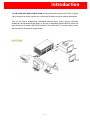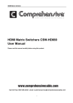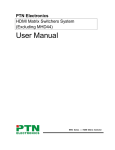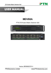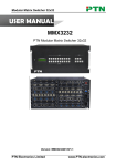
1
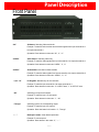
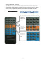
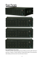
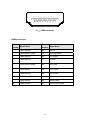
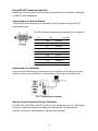
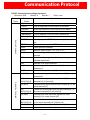
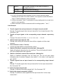
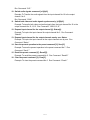
™
ASP-816H
™
ASP-168H
™
ASP-1616H
8 x 16, 16 x 8, 16x16 HDMI Matrix
User Manual
Manual Number: 101001
Safety and Notice
The ASP-816H, ASP-168H, and ASP-1616H 16x16 HDMI 1.3 Matrix has been tested for
conformance to safety regulations and requirements, and has been certified for international
use. However, like all electronic equipments, the matrices should be used with care. Please read
and follow the safety instructions to protect yourself from possible injury and to minimize the
risk of damage to the unit.
z Follow all instructions and warnings marked on this unit.
z Do not attempt to service this unit yourself, except where explained in this manual.
z Provide proper ventilation and air circulation and do not use near water.
z Keep objects that might damage the device and assure that the placement of this unit is on
a stable surface.
z Use only the power adapter and power cords and connection cables designed for this unit.
z Do not use liquid or aerosol cleaners to clean this unit. Always unplug the power to the
device before cleaning.
Introduction
The ASP-816H, ASP-168H, and ASP-1616H are high-performance professional HDMI 1.3 digital
signal switcher that can be used for cross switching of multiple sources to multiple destinations.
They can be used in broadcasting, multimedia meeting rooms, digital signage, education,
residential, and command control centers. It also has an adaptable compensation to extend the
input distance to 36 meters. With RS232 interface, it can work with a PC, remote control system,
and any other far-end control system devices.
~3~
Features
z HDMI 1.3 compliant
z HDCP compliant
z Allows any source to be displayed on multiple displays at the same time
z Allows any HDMI display to view any HDMI source at any time
z Supports 7.1 channel digital audio
z Supports default HDMI EDID and learns the EDID of displays if necessary
z The matrix master can switch every output channels to any HDMI inputs by push button, IR
remote control, or RS-232 control.
z Easy installation with rack-mounting
z Fast response time – 2~5 seconds for channel switch
~4~
Specifications
ASP-816H, ASP-168H, ASP-1616H
Specification
Video Input
Video Output
Input Connector
8 HDMI (816H), 16 HDMI (168H &
1616H)
Female HDMI
Output Connector
8 HDMI (816H), 16 HDMI (168H &
1616H)
Female HDMI
Input Level
T.M.D.S. 2.9V/3.3V
Output Level
T.M.D.S. 2.9V/3.3V
Input Impedance
75Ω
Output Impedance
75Ω
Gain
0 dB
Bandwidth
340 MHz (10.2 Gbit/s)
Video Signal
HDMI 1.3 standard full digital
T.M.D.S signal
Max Time-delay
5nS (±1nS)
Input
Output
Video General
Switching Speed
EDID and DDC
Management
HDCP Management
200ns (Max.)
Crosstalk
<-50dB@5MHz
Supports Extended Display Identification Data (EDID) and Display Data Channel (DDC) data
using DVI and HDMI standards, EDID and DDC signals are actively buffered. The built-in
EDID/DDC database can analyze these two signals, mix them, and realize the handshake of
them internally.
Compliant with High-bandwidth Digital Content Protection (HDCP) using DVI and HDMI 1.3
standards. The built-in HDCP management technology can analyze HDCP key, and realize the
handshake internally.
Control Parts
Serial Control Port
RS-232, 9-pin female D connector
Pin Configurations
2 = TX, 3 = RX, 5 = GND
IR Remote
Default IR remote
Front Panel Control
Buttons
Options
TCP/IP control
General
Power Supply
100VAC ~ 240VAC, 50/60Hz
Power Consumption
25W
Temperature
-20 ~ +70℃
17 5/16” (19” with Ears) W x 5.25”
H x 12 11/16” D
(3U high, full rack wide)
Humidity
10% ~ 90%
Product Weight
19lbs
Case Dimension
~5~
Packaging
ASP-816H or ASP-168H or ASP-1616H Matrix Switcher
depending on model ordered
IR remote
RS-232 Communication Cable
Power Supply Cable
CD
User Manual and Warranty
~6~
Panel Description
Front Panel
“AV”
AV button: Switching Video and Audio
Example: To transfer both the video and the audio signals from input channel No.3
to output channel No.4.
Operation: Press buttons in this order “AV”, “3”, “4””.
“VIDEO”
Video button: Switching Video only
Example: To transfer video signals from input channel No.3 to output channel No.4.
Operation: Press buttons in this order “VIDEO”, “3”, “4”.
“AUDIO”
Audio button: Not Used on these models
Example: To transfer audio signals from input channel No.2 to output channel No.3.
Operation: Press buttons in this order ““AUDIO”, “2”, “3””.
“1,2,3...16”
I/O Keypads: Number keys for I/O channels.
Example: To transfer input channel No.3 to output channel No.1
Operation: Press buttons in this order: “3” in INPUT area, “1” in OUTPUT area.
“All”
Switching one input to all outputs.
Example: To transfer input 1 to all outputs.
Operation: Press buttons in this order: “1”, “All”.
“Though”
Switching input to the corresponding output.
Example: To transfer input 2 to output 2
Operation: Press the button in this order: “2”, “Though”
“←”
Backspace button: Clear latest input button.
Example: To cancel input 3
Operation: Press button in this order: “3”, “ ← ”
~7~
“UNDO”
Undo button: Undo switching command.
Example: To cancel you latest switching status: input 3 through output 5
Operation: Press the button in this order: “3” input area, “5” output area, “UNDO”
Command Format for the Switching Operation
The switcher could be controlled directly using the buttons from the front control panel.
“Menu” + “Input Channel” + “Output Channel 1”
“Menu”: “AV”, “Audio”, “Video”
“Input Channel”: Select the number of input channel to be controlled
“Output Channel”: Select the number of output channels to be controlled
Examples of Operation
Example 1:To transfer video and audio signals from input channel No.1 to output channel No.3, 4:
AV
Video
Audio
1, Press the button for switching mode “AV” for the combined video and audio
mode (“Audio” for the audio switching mode only (note: does not apply on
these models); “Video” for the video switching mode only)
1
2
3
4
2, Press the button for input channel number“1”
2
2
3
3
4
4
3, Press the button for the first output channel number “3”
4, Press the button for the second output channel number “4”
Audio/Video switching from “1” to “3” and “4” is now successfully done.
~8~
EDID Management
Operation of the EDID management
The ASP matrix switcher has built in the EDID management database. The EDID
management can be automatic, manual, and factory restored.
Automatic EDID
The ASP matrix switcher has built in the EDID data, which can communicate with the
displayers and video source automatically. When the displays or video sources are
connected to the ASP matrix switcher, they will share the EDID/DDC information with the
matrix switcher.
The ASP EDID database includes the most popular display data. You can manually refresh
the EDID data to update the EDID data base.
EDID hand-shake priority
The EDID refresh ports have the priority grade, ranging from output 1 to output 8 in priority
order. It means the output 1 is the highest priority to exchange the EDID data, and then
output 2 all the way to output 8 which has the least priority.
When the user carries out the EDID erase/refresh function, the ASP will detect the output
priority and exchange the EDID data with the available most priority output port.
EDID management by RS232 commands
When you need to refresh the EDID data of the ASP matrix switcher, you can manually
exchange the EDID data by sending the RS232 command “EDIDMOn.” (Please notice the
text-transform, and the period at the end.)
Erase and Refresh the EDID data
When the “EDIDMOn.” is sent, the ASP matrix switcher will copy the EDID data from the
output port with priority. It means the ASP will erase the old EDID data, and fully copy the
EDID data from the display which is connected to the highest priority output port.
EDID restore to factory default
When you send the “EDIDMInit.” to the matrix switcher, it will recover the factory default
EDID data.
RS232 feedback:
When the “EDIDMOn.” or “EDIDMInit.” is correctly sent all the connected displays will be
~9~
blank for 2~3 seconds and recover again. The ASP matrix switcher will send out a RS232
feedback command of “EDIDMOn.” or “EDIDMInit.”.
EDID management by buttons
When you need to recover the ex-factory default EDID data set, you can send the RS232
command or press the buttons of the front panel/IR remote to make it work.
Erase and Refresh the EDID data
Keep pressing the arrow button “<-” for 30 seconds all the LED of “<-” will be on for 10
seconds. It then enters the EDID setting status.
Pressing “Input 2” button and “Undo” button all the outputs will be blank for 3 seconds, to
carry the “EDIDMOn.” command to refresh the EDID.
EDID restore to factory default
Keep pressing the button “<-” for 30 seconds and all the LED of “<-” will be on for 10
seconds. It enters the EDID setting status.
Pressing “Input 1” button and “Undo” button all the outputs will be blank for 3 seconds, to
carry the “EDIDInit.” command to restore the EDID to factory default.
~ 10 ~
Using a Remote Control
The matrix switcher can be controlled using the infrared remote control. The function
buttons on the remote control are the same as the ones on the front panel. The remote
control shares the same control operation and command format as the front panel.
Inputs 0~9,
and “10+” for
more
Menu, for
switching and
functions
Outputs 0~9,
and “10+” for
more
~ 11 ~
Rear Panels
Input and Output Connectors
The ASP-1616H has 16 input and output female HDMI ports while the ASP-816H has 8
inputs and 16 Outputs. The ASP-168H has 16 inputs and 8 outputs. Port numbers and
other labeling can be found on the rear silk screen of the unit.
~ 12 ~
F5—3 HDMI connector
HDMI pin function
Pin
Signal Name
Number
Pin
Signal Name
Number
1
TMDS Data 2+
20
SHELL
2
TMDS Data 2 Shield
19
Hot Plug Detect
3
TMDS Data 2-
18
+5V Power
4
TMDS Data 1+
17
Ground
5
TMDS Data 1 Shield
16
DDC Data
6
TMDS Data 1-
15
DDC Clock
7
TMDS Data 0+
14
No Connect
8
TMDS Data 0 Shield
13
CEC
9
TMDS Data 0-
12
TMDS Clock-
10
TMDS Clock+
11
TMDS Clock Shield
~ 13 ~
Using RS-232 Communication Port
Besides the front control panel and IR remote, the matrices can be controlled via Ethernet
or RS-232 communication port.
Connecting to a Control System
The matrices can be controlled by several kinds of control systems using the RS-232
communication port.
This RS-232 communication port is a female 9-pin D connector.
No.
Pin
Function
1
2
3
N/A
Tx
Rx
Unused
Transmit
Receive
4
5
6
7
N/A
Gnd
N/A
N/A
Unused
Ground
Unused
Unused
8
9
N/A
N/A
Unused
Unused
Connecting to a Computer
Users can control the switcher by connecting it to the computer and by using the control
software. (Please refer the details in Communication Protocol and Command Codes)
F 5-2 Connecting to computer
How to Connect Input and Output Terminals
The ASP-816H, ASP-168H, and ASP-1616H can have multiple sources, e.g.: DVD players,
computers, graphic workstations and digital showing platforms. The signal can be
outputted to projectors, video recorders, displayers and amplifiers.
~ 14 ~
Communication Protocol
RS-232 Communication settings & protocol:
Baud rate: 9600
Data bit: 8
Stop bit: 1
Command
Types
Command
Codes
Parity: none
Functions
System Command
/*Type;
Request model’s information
/%Lock;
Lock the keyboard of control panel on the Matrix.
/%Unlock;
Unlock the keyboard of control panel on the Matrix
/^Version;
Request firmware version
/:MessageOff;
Turn off feedback. It will only show “Switcher OK”
/:MessageOn;
Turn on feedback
EDIDMOn.
Manually adjust the EDID with the most priority output
port.
EDIDMInit.
Recover the factory default EDID data
Undo.
Cancel previous operation
Demo.
Switch to “demo” mode, 1->1, 2->2, 3->3 …
[x1]All.
Transfers all signals from input channel [x1] to all output
channels
All#.
Transfers all input signals to the corresponding output
channels respectively.
Operation Command
All$.
Switches off all output channels.
[x1]#.
Transfers signals from input channel [x1] to output
channel [x1].
[x1]$.
Switches off output channel [x1].
[x1] V[x2].
Transfers video signals from input channel [x1] to output
channel [x2].
[x1]
V[x2],[x3],[x4].
Transfers video signals from input channel [x1] to output
channels [x2], [x3] and [x4].
[x1] A[x2].
Transfers audio signals from the input channel [x1] to the
output channel [x2].
[x1]
A[x2],[x3],[x4].
Transfer the audio signals from the input channel [x1] to
the output channels [x2], [x3] and [x4].
[x1] B[x2].
Transfers both video and audio signals from input
channel [x1] to output channel [x2].
[x1]
B[x2],[x3],[x4].
Transfer both video and audio signals from input channel
[x1] to output channels [x2], [x3] and [x4].
Status[x1].
Request input channel for output channel [x1].
Status.
Request input channel for output channels one by one.
~ 15 ~
Save[Y].
Save present operation to the preset command [Y].
[Y] ranges from 0 to 9.
Recall[Y].
Recall the preset command [Y]
Clear[Y].
Clear the preset command [Y]
Note:
1. [x1], [x2], [x3] and [x4] are the symbols of input or output channels ranged
according to the model of the matrix switcher. If the symbols exceed the effective
range, it would be taken as a wrong command.
2. In above commands, “[”and “]” are symbols for easy reading and do not need to be
typed in actual operation.
3. Please remember to end the commands with the ending symbols “.” and “;”.
Detail Examples:
1.
Transfer signals from an input channel to all output channels: [x1]All.
Example: To transfer signals from the input channel No.3 to all output channels. Run
Command: “3All.”
2.
Transfer all input signals to the corresponding output channels respectively:
All#.
Example: The status of it will be: 1->1, 2->2, 3->3, 4->4……16->16.
3.
Switch off all output channels: All$.
Example: After running this command, there will be no signals on all the output
channels.
4.
Check firmware version: /^Version;
Unit will reply back with the current firmware version.
5.
Switch off feedback commands from serial port: /:MessageOff;
Switch off feedback information from the serial port. The unit will reply with “switch
OK” as the feedback after each operation.
6.
Switch on feedback command from serial port: /:MessageOn;
Switch on feedback information from the serial port. The unit will show status
information when it switches. Example: when switch 1->2 for Audio, it will reply back
with “A0102”.
7.
Transfer signals from an input channel to the corresponding output channel:
[x]#.
Example: To transfer signals from the input channel No.5 to the output channel No.5.
Run Command: “5#.”
8. Switch off output channel: [x]$.
Example: To switch off the output channel No.5. Run Command: “5$.”
9. Switch video signals command: [x1]V[x2].
Example: To transfer the video signals from the input channel No.3 to the output
channel No.5.
~ 16 ~
Run Command: “3V5.”
10. Switch audio signals command: [x1]A[x2].
Example: To Transfer the audio signals from the input channel No.10 to the output
channel No.2.
Run Command: “10A2.”
11. Switch both video and audio signals synchronously: [x1]B[x2].
Example: To transfer both video and audio signals from the input channel No.12 to the
output channels No.12,13,15. Run Command: “12B12,13,15.”
12. Request input channel for the output channel [x]: Status[x].
Example: To inquire the input channel for output channel No.3. Run Command:
“Status3.”
13. Request input channel for the output channels one by one: Status.
Example: To inquire the input channel to the output channels one by one. Run
Command: “Status.”
14. Save the present operation to the preset command [Y]: Save[Y].
Example: To save the present operation to the preset command No.7. Run
Command: “Save7.”
15. Recall the preset command [Y]: Recall[Y].
Example: To recall the preset command No.5. Run Command: “Recall5.”
16. Clear the preset command [Y]: Clear[Y].
Example: To clear the preset command No.5. Run Command: “Clear5.”
~ 17 ~
Limited 3 Year Warranty
Aurora Multimedia Corp. (“Manufacturer”) warrants that this product is free of defects in both
materials and workmanship for a period of 3 years as defined herein for parts and labor from
date of purchase. Motorized mechanical parts (Hard Drives, DVD, etc), mechanical parts
(buttons, doors, etc), remotes and cables are covered for a period of 1 year. Batteries are not
covered by this warranty. During the warranty period, and upon proof of purchase, the product
will be repaired or replaced (with same or similar model) at our option without charge for parts
or labor for the specified product warranty period.
This warranty shall not apply if any of the following:
A) The product has been damaged by negligence, accident, lightning, water, act-of-God or
mishandling; or,
B) The product has not been operated in accordance with procedures specified in operating
instructions: or,
C) The product has been repaired and or altered by other than manufacturer or authorized
service center; or,
D) The product's original serial number has been modified or removed: or,
E) External equipment other than supplied by manufacturer, in determination of manufacturer,
shall have affected the performance, safety or reliability of the product.
F) Part(s) are no longer available for product.
In the event that the product needs repair or replacement during the specified warranty period,
product should be shipped back to Manufacturer at Purchaser's expense. Repaired or replaced
product shall be returned to Purchaser by standard shipping methods at Manufacturer's
discretion. Express shipping will be at the expense of the Purchaser. If Purchaser resides outside
the contiguous US, return shipping shall be at Purchaser's expense.
No other warranty, express or implied other than Manufacturer's shall apply.
Manufacturer does not assume any responsibility for consequential damages, expenses or loss of
revenue or property, inconvenience or interruption in operation experienced by the customer
due to a malfunction of the purchased equipment. No warranty service performed on any
product shall extend the applicable warranty period.
This warranty does not cover damage to the equipment during shipping and Manufacturer
assumes no responsibility for such damage.
This product warranty extends to the original purchaser only and will be null and void upon any
assignment or transfer.
Aurora Multimedia Corp.
205 Commercial Court, Morganville, NJ 07751
Phone: (732) 591-5800 Fax: (732) 591-5801
www.auroramultimedia.com
~ 18 ~