1
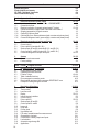
Part C
Special applications, functional checks, service, and order numbers
6/1-9/1
6
6.1
6.2
6.3
6.4
6.5
6.6
6.7
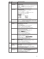
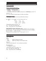
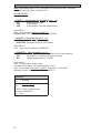
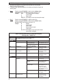
Special applications
Use in hazardous areas
RS 232 adapter incl. CONFIG software (option)
Stable signal outputs when measuring tube empty
Pulsating flow
Rapid changes in flowrate
Unsteady display and outputs
HART interface
6/1-6/4
6/1
6/1
6/2
6/3
6/3
6/4
6/5-6/6
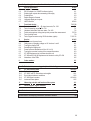
7
7.1
7.2
7.3
7.4
7.5
7.6
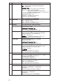
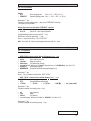
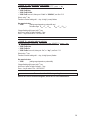
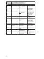
Functional checks
Zero check with IFC 090 / D, signal converter, Fct. 3.03
Test of measuring range Q, Fct. 2.01
Hardware information and error status, Fct. 2.02
Faults and symptoms during start-up and process flow measurement
Test of primary head
Test of signal converter using GS 8A simulator (option)
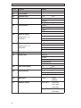
8
8.1
8.2
8.3
8.4
8.5
8.6
8.7
8.8
8.9
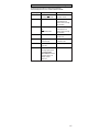
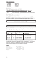
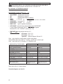
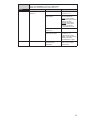
Service
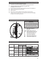
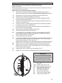
Replacement of power fuses
Changeover of operating voltage on AC Versions 1 and 2
Turning the display PCB
Retrofitting the display unit
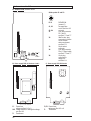
Power fuses and illustrations to Sect. 8.1 to 8.4
Turning the converter housing of the compact flowmeters
IFC 090 Replacement of converter electronic unit
IFC 080 and SC 80 AS Replacement of electronic unit by IFC 090
Illustrations of the PCBs
9
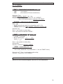
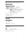
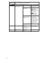
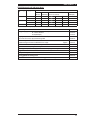
Order numbers
Part D
Technical data, measuring principle and block diagram
10/1-12/1
10
10.1
10.2
10.3
10.4
10.5
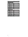
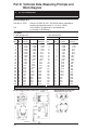
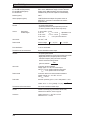
IFC 090 Technical data
Full-scale range Q100%
IFC 090 F and ZD Dimensions and weights
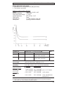
Error limits at reference conditions
IFC 090 Signal converter
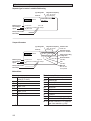
Instrument name plates
10/1-10/5
10/1
10/1
10/2
10/3-10/4
10/5
11
Measuring principle and function of the system
11/1
12
Block diagram - signal converter
12/1
Part E
Index
Printed form to accompany flowmeters returned to Krohne
7/1-7/12
7/1
7/1
7/2
7/3-7/8
7/9
7/10-7/12
8/1-8/5
8/1
8/1
8/1
8/2
8/2
8/3
8/3
8/4
8/5
9/1
E1-E2
E3
0/2