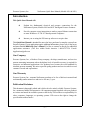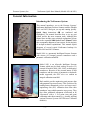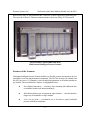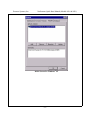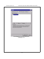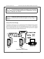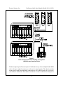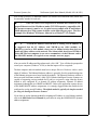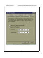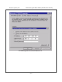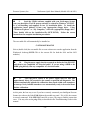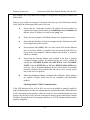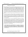
1
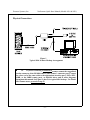
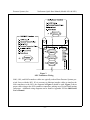
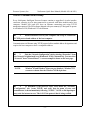
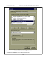
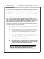
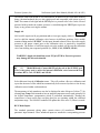
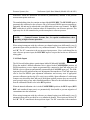
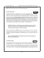
Intelligent Pressure Scanner
Quick Start Manual
(Models 9016 and 9021)
September 1998
NetScanner™ System
Visit us on the web:
www.PressureSystems.com
NetScanner
Intelligent Pressure Scanners
Quick Start Manual
(Models 9016 and 9021)
September 1998
Pressure Systems, Inc.
34 Research Drive
Hampton, Virginia 23666
(757) 865-1243
FAX (757) 865-8744
Internet: www.PressureSystems.com
Pressure Systems, Inc.
NetScanner Quick Start Manual (Models 9016 & 9021)
This page intentionally left blank
i
Pressure Systems, Inc.
NetScanner Quick Start Manual (Models 9016 & 9021)
C
ONGRATULATIONS! You have
purchased state of the art intelligent
pressure scanners. We are confident
you will find this equipment easy to use,
accurate, and an excellent value.
ii
Pressure Systems, Inc.
NetScanner Quick Start Manual (Models 9016 & 9021)
This page intentionally left blank
iii
Pressure Systems, Inc.
NetScanner Quick Start Manual (Models 9016 & 9021)
Introduction
This Quick Start Manual will:
g
Explain the fundamental electrical and pressure connections for the
NetScanner System, Models 9016 and 9021 Intelligent Pressure Scanners.
g
Provide computer set-up instructions to make a proper Ethernet connection
on most Windows® 95 /98/ NT based personal computers.
g
Instruct you on using the PSI start-up software to acquire data.
This Quick Start Manual is intended for users who have purchased a complete system from
Pressure Systems. If your application requires additional information, please refer to the larger
and more detailed 9000 Series User’s Manual. Feel free to contact us directly for additional
applications assistance. (Toll free within North America: 1-800-678-7226. E-mail:
[email protected].
Our Company
Pressure Systems, Inc., a Roxboro Group company, develops, manufactures, and services
pressure measuring instruments where the highest level of traceable accuracy is required for
aerospace and industrial applications. Our products have become the world standard for
electronic pressure scanning. We strive to provide quality products and services which exceed
customer’s needs and expectations.
Our Warranty
Pressure Systems, Inc., warrants NetScanner products to be free of defects in material and
workmanship under normal use and service for one (1) year.
Publication Disclaimer
This document is thoroughly edited and is believed to be entirely reliable. Pressure Systems,
Inc., assumes no liability for inaccuracies. All computer programs supplied with your products
are written and tested on available systems at the factory. PSI assumes no responsibility for
other computers, languages, or operating systems. PSI reserves the right to change the
specifications without notice.
-1-
Pressure Systems, Inc.
NetScanner Quick Start Manual (Models 9016 & 9021)
This page intentionally left blank
-2-
Pressure Systems, Inc.
NetScanner Quick Start Manual (Models 9016 & 9021)
General Information
Introducing the NetScanner System
This manual introduces you to the Pressure Systems’
NetScanner Intelligent Pressure Scanner modules (Models
9016 and 9021) and gets you up and running quickly.
Quick Start instructions (4) are numbered and
highlighted. The manual describes how to set up your
system and do the most common tasks. Although this
manual does include some technical explanations, please
refer to the expanded 9000 Series User’s Manual, which
also accompanies shipment of your system, for the majority
of in-depth technical explanations. This manual depicts
diagrams of several typical NetScanner hookups for
Models 9016 and 9021 scanners.
Model 9016
Model 9016 is a pneumatic Intelligent Pressure Scanner
with sixteen (16) integral pressure transducers and a
pneumatic calibration manifold.
Model 9021 is an all-media Intelligent Pressure
Scanner which may be fitted with up to twelve (12)
external all-media (9400, 9401, 9402, or third-party)
transducers. Because of the external nature of this
transducer and the variety of pneumatic or hydraulic
media supported, the 9021 does not contain an
integral calibration manifold.
Model 9021
Both models provide engineering unit pressure data
with guaranteed system accuracy. This is achieved by
reading factory-determined pressure and temperature
engineering unit (EU) calibration data from their
transducers’ non-volatile memories at power-up. They
also allow additional adjustment coefficients to be
“fine-tuned” with a 1- or 2-point (zero and span)
calibration under host control (e.g., possibly utilizing
optional Pressure Systems 903x Pressure Calibrator
modules).
-3-
Pressure Systems, Inc.
NetScanner Quick Start Manual (Models 9016 & 9021)
Both models may be interconnected into a network via their ruggedized connecting port.
They provide 10-Base-T Ethernet communications to their host using TCP/IP protocol.
PSI NetScanner (Model 98RK and 9816)
Multi-channel Intelligent Pressure Scanner
Features of the Scanners
NetScanner Intelligent Pressure Scanner modules are flexible pressure measurement devices
intended for use in test and production environments. The 9016 has sixteen (16) channels and
the 9021 has twelve (12) channels, each with individual pneumatic or all-media transducers
per channel. The most distinctive features are highlighted below:
g
Pre-calibrated transducer — a memory chip containing full calibration data
is embedded within each internal transducer.
g
Individual transducer per measurement input channel — mixed transducer
ranges may be installed in a single module.
g
Low cost per point — per-channel cost is less than a typical industrial
pressure transducer/transmitter.
-4-
Pressure Systems, Inc.
NetScanner Quick Start Manual (Models 9016 & 9021)
g
High accuracy — Model 9016 pressure scanners are capable of accuracies
better than ±0.05%. Model 9021 pressure scanners provide accuracies better
than ±0.10% FS. Accuracy is maintained for six (6) months after calibration.
g
Low thermal errors — each transducer of a pressure scanner module contains
an individual temperature sensor and thermal calibration data for internal use
by software correction algorithms. Thermal errors are reduced to as low as
±0.001%/0C over the calibrated temperature range.
g
Re-zero upon demand (Model 9016) — an integrated calibration valve allows
for automatic re-zero adjustment calibration of dry gas transducers to null
offset drift errors.
g
Ease of transducer replacement — factory calibrated transducer assemblies
may be stocked and rapidly replaced in the field. Storage of thermal
data within the transducer allows for “plug and play” transducer replacement.
g
Ease of calibration — each 9016 module contains a pneumatic calibration
manifold and software commands to automatically perform re-zero and span
adjustment calibrations. New offset and gain coefficients that result from the
most recent calibration may be stored in non-volatile transducer memory.
g
Measurement flexibility — each 9021 module is capable of measuring general
purpose voltage signals on any channel not populated with a 9400-type
transducer. Full scale ranges of ±50mV, ±100mV, ±250mV, and ±4500mV
are supported through programmable gain amplifier circuitry.
g
Ease of use — modules have simple command sets and provide engineering
unit (EU) outputs. They may interface directly to a desktop or laptop
computer or they may be interconnected into a large network controlled by
many types of host computers.
g
Connectivity — use of industrial-standard communications network protocols
to control and read data from NetScanner modules allows distribution to the
point of measurement and ensures compatibility with third-party hardware and
software.
-5-
Pressure Systems, Inc.
NetScanner Quick Start Manual (Models 9016 & 9021)
Physical Connections
Figure 1
Typical 9016 Scanner Hookup Arrangement
4
1a.
If you are connecting a Model 9016 scanner, connect the ruggedized
circular connector of the PSI 9080 cable to your scanner’s connector port. Connect
the other end of the same cable to the appropriate interface port ( PSI’s 9IFC,
90DB, or the 98RK remote port), as depicted above and in other diagrams
throughout this manual. See Figure 1, above, for typical 9016 hookup. For Model
9016 scanner users, proceed to step #2.
-6-
Pressure Systems, Inc.
NetScanner Quick Start Manual (Models 9016 & 9021)
Figure 2
Typical 9021 Scanner Hookup Arrangement
4
1b.
If you are connecting a Model 9021 scanner, connect the ruggedized
circular connector of the PSI 9080 cable to your scanner’s connector port. Connect
the other end of the same cable to the appropriate interface port (PSI’s 9IFC,
90DB, or the 98RK remote port), as depicted above and in other diagrams
throughout this manual. See Figure 2 above for typical 9021 hookup.
Model 9021 pressure scanner interfaces to twelve (12) external transducers or signal sources.
Although this module is intended primarily for use with the Pressure Systems, Inc., Models
9400, 9401, or 9402 All-Media Transducers, it may also be used with many third party
transducers with suitable analog outputs (output less than the 9021 maximum input range of
±5VDC). When using external transducers, the 9021 modules provide a +12VDC unregulated
supply voltage to power the transducer. PSI transducers (9400, 9401, 9402) may be installed
as follows:
4
1c.
For the Model 9021 scanner, connect the transducer’s 9096
cable to the scanner as depicted in Figures 2 and 3.
-7-
Pressure Systems, Inc.
NetScanner Quick Start Manual (Models 9016 & 9021)
Figure 3
9021 Transducer Wiring
9400, 9401, and 9402 transducer cables are typically ordered from Pressure Systems prewired for use with the 9021. If it is necessary to fabricate interface cables to interface the
940x transducer to the 9021, the diagrams in Figure 3 should be used. Figure 3 shows
proper cable wiring to the 9021 transducer connectors, making use of 9-pin D-shell mating
connectors. Additional wiring diagrams can be found in Appendix E of the 9000 Series
User’s Manual.
-8-
Pressure Systems, Inc.
NetScanner Quick Start Manual (Models 9016 & 9021)
Network Communications Hookup
Every NetScanner Intelligent Pressure Scanner contains a ruggedized, circular interface
connector, allowing it to be inter-connected in a network with other modules and a host
computer. Models 9016 and 9021 have an Ethernet connecting port using TCP/IP
transmission protocol. The PSI software (shipped with your scanner(s)) is designed to operate
in a Windows®95/98,Windows® NT environment.
4
2.
Install an Ethernet card in your computer and set up or confirm the
TCP/IP protocol and address of the host computer.
Communications via Ethernet using TCP/IP protocol utilizes module address designations and
requires the host computer to have a compatible address.
4
3.
Find the “Network-Configuration” tab by selecting “Properties” from
the Network Neighborhood icon (Windows® 95/98). Alternatively, you can select
“Network” from “Control Panel”. A screen example is shown on the next page.
NOTE:
Windows®95 and Windows®98 screens are identical. Windows®NT
screens are shown after the Windows®95/98 depictions.
4
4.
To determine if the protocol exists, scroll down the “NetworkConfiguration” tab, locate TCP/IP, and verify that the name of your card
manufacturer is shown immediately following “TCP/IP.” NOTE: a dial-up adapter
may exist for internet access. This is NOT the protocol that is being verified.
-9-
Pressure Systems, Inc.
NetScanner Quick Start Manual (Models 9016 & 9021)
Windows®95/98 Network Configuration Screen
Network screens for Windows®NT are shown on the next page.
- 10 -
Pressure Systems, Inc.
NetScanner Quick Start Manual (Models 9016 & 9021)
Initial Screen for Windows® NT
- 11 -
Pressure Systems, Inc.
NetScanner Quick Start Manual (Models 9016 & 9021)
Screen Depicting Correct TCP/IP Protocol
in Windows® NT
- 12 -
Pressure Systems, Inc.
NetScanner Quick Start Manual (Models 9016 & 9021)
4
5.
If the TCP/IP protocol bound to the installed card is not found, it
must be added. To add, select ADD from the network “Communications” tab. Select
“Protocol,” “Microsoft,” and “TCP/IP.”
4
6.
Connect the Ethernet cable between the PSI 9IFC, 90 DB, or the
98RK host port and the Ethernet card of the host computer. (See either Figure 1 or
Figure 2)
Ethernet Host Port Hookup
The Ethernet connecting ports of every Model 9016 and 9021 Intelligent Pressure Scanner
module and its host computer may be interconnected in a “star” network via a standard 10Base-T interconnection hub, such as the PSI 90DB Distribution Center. These standard
devices will have their own power requirements. Such a hub treats the host computer
connection and all NetScanner module connections alike.
Figure 4
Typical Multi-Scanner Hookup
- 13 -
Pressure Systems, Inc.
NetScanner Quick Start Manual (Models 9016 & 9021)
Figure 5
Rack-mounted NetScanner Hookup Arrangement
(98RK Scanner Interface Rack)
The above figure depicts Pressure Systems’ NetScanner array, where multiple Model 98RK
racks with up to eight (8) scanners per rack may be netted together. The chassis provides
scanner power supply and pneumatic connections as well as hub circuitry for up to twelve
(12) 10-Base T connections. This enables each chassis to connect with the host computer as
- 14 -
Pressure Systems, Inc.
NetScanner Quick Start Manual (Models 9016 & 9021)
well as with up to three (3) additional scanners (or scanners and calibration units) which may
be externally attached to each rack.
4
7.
Once the correct TCP/IP protocol is installed and verified for the
proper Ethernet card, the IP address (under TCP/IP Properties), compatible with
the pressure scanner(s), must be set. A typical screen example with IP and Subnet
Mask addresses for a 9016 scanner is shown on the following two pages. The first
example if for Windows®95/98 users, followed by a Windows® NT example.
4
8.
To set the PC address: Select the new or existing TCP/IP address. It
is suggested that the IP Address read 200.200.yyy.zzz (9016 module), or
200.201.yyy.zzz for a 9021 module, where zzz is a unique location that does not
match any other address on the network. The Subnet mask should read 255.0.0.0.
Select OK. The host computer is now set to communicate via the Ethernet card to
the 9016/9021 module. (See typical screen example, next two pages.)
After you set the IP address and the subnet mask, click “OK.” You will then be prompted to
restart your computer (Windows®95/98) so that the inputs will be recognized.
The host computer and each module must have a unique Ethernet Hardware Address and a
unique IP Address. The Ethernet Hardware address is generally fixed (at manufacturing time
of the Ethernet microprocessor board inside the module). The Ethernet Hardware address is
shown on each NetScanner module’s label. PSI’s Ethernet Intelligent Pressure Scanners are
capable of supporting various methods for IP address assignment, using either the factory
default or user configured IP or dynamic IP address assignment. Dynamic IP address
assignment is through the use of RARP and BOOTP. Unless your application requires the use
of the RARP/BOOTP address assignments, it is strongly suggested that the module be left
configured to use the stored IP address. The default method is typically the simplest method
for using the Intelligent Pressure Scanner.
If you desire to use the alternate method for assigning an IP address to your Ethernet module,
refer to the 9000 Series User’s Manual for procedures in using the RARP/BOOTP dynamic
address assignment.
- 15 -
Pressure Systems, Inc.
NetScanner Quick Start Manual (Models 9016 & 9021)
TCP/IP Properties Screen for Windows®95/98
- 16 -
Pressure Systems, Inc.
NetScanner Quick Start Manual (Models 9016 & 9021)
TCP/IP Properties Screen for Windows® NT
- 17 -
Pressure Systems, Inc.
NetScanner Quick Start Manual (Models 9016 & 9021)
4
9.
Load the ST9016 software supplied with your NetScanner System
onto your hard drive. The PSI start-up software is written for Windows® 95/98/NT.
It is self-installing and supplied on two (2) installation disks. To install the
application, insert diskette #1 into your (appropriate) floppy drive. Using
“Windows Explorer” or “My Computer,” select the (appropriate) floppy drive.
Then, double click on the installation file (SETUP.EXE). Follow the screen
instructions for complete installation procedures.
The executable file will automatically be installed as:
C:\ST9016\ST9016.EXE
Select (double click) the executable file or create a shortcut to run the application from the
Windows® desktop.(NOTE: This is the execute file for both the 9016 and the 9021
modules.)
4
10.
Plug the power supply into the receptacle on the back of the PSI 9IFC
and then to any compatible AC electrical outlet. If you are using a 90DB or the
98RK, plug directly into any compatible AC electrical outlet.
4
11.
Turn the power switch of the power supply unit ON and wait
approximately thirty (30) seconds for the scanner to perform self-diagnostics. The
scanner automatically uploads the calibration data stored within each transducer
at start-up. Newly installed transducers are automatically ready to be used without
further calibration.
At this point, the best way to see if you have correctly connected your Intelligent Pressure
Scanner is to observe the Link (LNK) light on the module top panel. If it is ON, the scanner
is correctly connected. If the LNK light is not ON, re-trace your steps to find the connection
error. You may also use the ping utility as described in the Troubleshooting Guide in this
manual.
- 18 -
Pressure Systems, Inc.
NetScanner Quick Start Manual (Models 9016 & 9021)
4
12.
Select (double click) the executable file (ST9016.EXE) using
“Windows Explorer” or “My Computer” or select (double click) the shortcut icon
(that you created) from the desktop. The main screen of the 9016/9021 software is
shown below.
- 19 -
Pressure Systems, Inc.
NetScanner Quick Start Manual (Models 9016 & 9021)
4
13.
Select (click with your mouse) Init, and then 9016/9021 Modules, as
shown on the following screen picture.
- 20 -
Pressure Systems, Inc.
NetScanner Quick Start Manual (Models 9016 & 9021)
When you select (click on) Init-9016/9021Modules, the following drop-down menu will
appear:
From this menu you will need to choose whether you want to enter module IP addresses
manually or from a file. If you choose File, you must have previously created that file with all
the module addresses you want to enter. To initialize using a file:
g
Create an ASCII test file. (Several methods may be used. Two common tools
are Windows® 95 Notepad or your DOS Text Editor.)
g
List each scanner on a separate line. Write the IP address, insert a space, and
then write the scanner serial number. (The “,” [comma] character may be used
to comment out a line. A line starting with “,” is not used during Start-up.)
g
Store the file in the same directory as ST9016.EXE for easy access.
EXAMPLE: 200.200.1.123 191 (This scanner is a Model 9016 with serial number 191)
200.201.1.12 322 (This scanner is a Model 9021 with serial number 322)
200.200.1.124 192 (This scanner is a Model 9016 with serial number 192)
200.200.1.125 193 (This scanner is a Model 9016 with serial number 193)
If you choose to manually input the addresses, the screen on the next page will appear, on
which you can manually input the module addresses.
- 21 -
Pressure Systems, Inc.
NetScanner Quick Start Manual (Models 9016 & 9021)
4
14.
When you choose to manually insert the module addresses, the
following screen will appear. Type in each module address (obtained from the label
on the module cover plate), and the module serial number (also obtained from the
label on the module cover plate). Click OK and proceed to the next step.
- 22 -
Pressure Systems, Inc.
NetScanner Quick Start Manual (Models 9016 & 9021)
Pressure Connections
All pneumatic connections for the Model 9016 are found on the instrument top panel. The
function of each input port is clearly engraved or printed next to each input. Connections are
through bulge tubing, compression fittings, or special user-supplied fittings on the tubing
plate. All pneumatic inputs to these modules should contain dry, non-corrosive gas only. For
Model 9021, all pneumatic or hydraulic connections are to the individual 9400, 9401, or 9402
all-media transducers mounted externally from the module itself.
Currently, all 9016 standard Intelligent Pressure Scanners are supplied with the purge/leak
check calibration manifold. Through software commands to the 9016, this valve may be
placed in one of four positions; RUN, CAL, PURGE, or LEAK. 9016 modules without the
purge option may be placed in the CAL or RUN modes of operation only. Pneumatic input
requirements for these four operating positions are described in following sections.
Here are some guidelines which should be followed when installing pressure connections to
all NetScanner Intelligent Pressure Scanner modules.
g
It is always a good idea to wear safety glasses when working with pressurized
lines.
g
Ensure that your input pressure will not exceed the proof pressure ratings of
the corresponding instrument transducer. Applying excessive pressure to
measurement inputs can permanently damage the pressure transducers.
g
Ensure that all tubing material is rated for the expected pressure and
environmental conditions. Failure to use the proper tubing material may result
in ruptured lines and possible personal injury.
g
Ensure all high pressure lines are properly secured.
g
Place retaining springs over all bulge tube fittings to ensure pneumatic lines
remain attached and leak free. Springs should be pushed down on connections
so that half of the spring length extends past the tube bulge.
WARNING: Introduction of contaminants to the module pneumatic
inputs may damage transducers, manifolds, and O-ring seals.
- 23 -
Pressure Systems, Inc.
NetScanner Quick Start Manual (Models 9016 & 9021)
The VENT connection should be left unterminated. In addition to the NetScanner modules
being vibration-hardened, they are also splash-proof and compatible with various types of
fluids. The scanner is leak tight and the VENT port is a pressure relief valve. In the event of
pressure build-up inside the scanner, pressure is vented through the VENT port to prevent
injury to any person servicing the scanner.
Supply Air
9016 only
9016 models require an 80 psig minimum air (or inert gas) supply which is
used to shift the internal calibration valve between its different positions. Each module
contains a fitting marked “SUPPLY” for this input. Internal solenoid valves direct this supply
pressure to the proper control port on the calibration valve as required by instrument
commands. The absence of sufficient supply air to the module will prevent the calibration
valve from shifting into requested positions (i.e., RUN, CAL, PURGE, LEAK)
WARNING: Supply air should not exceed 125 psi (875 kPa). Excessive pressure
may damage the internal solenoids.
4
15.
(Model 9016 only) Connect 80-125 psig dry air to the SUPPLY port.
This is the power used to move the internal calibration valve between the four
locations; RUN, CAL, PURGE, and LEAK.
Select Re-zero from the Calibration menu. This will perform a Re-zero calibration and
report the amount of offset which has automatically been corrected (relative to the factory
calibration stored within each transducer).
The temperature of each transducer can also be displayed in units of degrees Celsius (0C) by
selecting Acq. Temp. Each transducer has an integral temperature sensor used primarily for
the digital temperature compensation which is performed automatically. Reading the
temperature is most useful when verifying that you are operating within the calibrated
temperature range. The 9016/9021 modules will update this value once 15 (fifteen) seconds.
RUN Mode Inputs
9016 only
The standard pneumatic tubing plates contain sixteen (16) numbered
pneumatic input channels. These numbered inputs are attached to corresponding pressure
- 24 -
Pressure Systems, Inc.
NetScanner Quick Start Manual (Models 9016 & 9021)
transducers inside the instrument and should be pneumatically attached to the pressure
measurement points under test.
The standard tubing plate also contains an input labeled RUN REF. The RUN REF input is
pneumatically connected to the reference side of all internal DH200 pressure transducers.
Optionally, the unit may be ordered with a true differential (reference per channel). The RUN
REF connection is used for situations where all channels have one reference pressure. This
input may also be left unattached to provide atmospheric reference pressure.
NOTE:
Contact Pressure Systems, Inc., for special considerations when
operating at high reference pressures.
When using instruments with the reference per channel option (true differential), two (2)
pneumatic inputs will be provided for every numbered channel. These inputs are labeled “P”
and “R.” The “P” connection is the test pressure input pressure. Since each channel has its
own reference pressure input, the RUN REF input is not provided on the true differential
tubing plate.
CAL Mode Inputs
9016 only
The 9016 model tubing plates contain inputs labeled CAL and CAL REF.
When the module’s internal calibration valve is placed in the CAL/REZERO position, all
DH200 transducer pressure inputs are pneumatically connected to the CAL input port. All
DH200 reference inputs are pneumatically connected to the CAL REF input port. The CAL
input may be used to perform on-line zero adjustment of the transducers. The CAL input may
also be used for DH200 span adjustment calibrations and accuracy tests if appropriate
pressure calibrators (such as the 903x series) are available. Span calibration of multi-range
scanners may also utilize the CAL port if the highest applied pressure does not exceed the
proof pressure rating of any other installed transducer, otherwise the individual transducers
must be calibrated with the valve in the RUN position.
When the internal calibration valve is in the CAL/REZERO position, the RUN inputs (RUN
REF and numbered input ports) are pneumatically dead-ended to prevent migration of
contaminants into the instrument.
When using instruments with the reference per channel option (true differential), two (2)
pneumatic inputs will be provided for every numbered channel. These inputs are labeled “P”
and “R”. The “P” connection is the test pressure input. The “R” connection is the transducer
- 25 -
Pressure Systems, Inc.
NetScanner Quick Start Manual (Models 9016 & 9021)
reference input pressure. Since each channel has its own reference pressure input, the RUN
REF input is not provided on the true differential tubing plate.
PURGE Mode Inputs
9016 only
Standard 9016 models are supplied with a purge/leak check feature. The
purge feature allows users to apply positive pressure to the PURGE input which will then be
vented out of the user input ports, forcing contaminants (such as moisture) out of the
pneumatic input lines. Note that on common reference 9016 scanners, only the numbered
input ports will be purged (RUN/REF is not purged). True differential 9016 scanners will
purge both the run and reference input ports for all channels. The purge supply provided to
the 9016 must always be a higher pressure than the highest pressure present on the input ports
of the module. The purge supply must also be capable of maintaining proper purge pressure
at the high flow rates encountered while the module is in the purge mode.
WARNING: Failure to provide proper purge supply pressure may result in
migration of moisture and contaminants into the 9016 module which can
result in permanent damage to module components.
When commanded into the PURGE position, the purge input pressure will be connected to
the numbered measurement input ports allowing for a flow of air away from the instrument.
The purge cycle should be terminated by commanding the 9016 into a non-purge mode, such
as CAL.
Purge cycles should NEVER be terminated by turning off the purge supply air
while in the PURGE position.
LEAK Mode Inputs
9016 only
The purge/leak check valve design includes a leak check feature capable of
testing the integrity of user pneumatic connections as well as those within the 9016 module.
For the leak mode to be used, all RUN mode pressure inputs must be dead-ended (closed)
by the user. (Contact the PSI Sales Department for availability of an external leak check
valve) When the 9016 is commanded into the LEAK position, the CAL input port will be
- 26 -
Pressure Systems, Inc.
NetScanner Quick Start Manual (Models 9016 & 9021)
pneumatically connected to the module run side inputs. Common reference modules will
connect only the numbered run side inputs to CAL (RUN REF is not charged). True
differential (reference per port) modules will connect both the measurement input and
reference port to CAL. While in the LEAK position, a test pressure may be applied thought
the CAL port which will charge the dead-ended run side tubulation.
NOTE: Test pressures applied to the CAL port during leak check operation must
not exceed the full scale pressure of any internal transducer.
Once the lines are charged, the 9016 may be commanded back to the RUN position. This will
reattach the charged run side lines to their corresponding internal transducer. Consecutive
pressure readings from the 9016 will now allow user calibration of the line leak rates. Once
returned to the RUN position, lack of pressure indicates a gross leak. A slowly declining
pressure indicates a slight leak. A leak is more difficult to detect as tubing volume increases.
In the case of true differential units where both sides of the sensor are pressurized with the
leak test pressure, an initial differential pressure of 0.0 psi should be measured when the unit
is placed in the RUN position. If the measurement or RUN side of the channel leaks at a rate
greater than the reference side, a resulting negative differential pressure will be measured.
Likewise, if the reference port tubing leaks at a rate greater than the measurement side, a
resulting positive differential pressure will be measured.
Acquiring Data
4
16.
(All Models) From the Acquire menu, select “Acquire Data” to read
the pressure of each channel on the screen. The pressure is displayed in
engineering units and also a proportion of transducer full scale on the individual
bar graphs.
- 27 -
Pressure Systems, Inc.
NetScanner Quick Start Manual (Models 9016 & 9021)
4
17.
(All Models) To stop data acquisition and freeze the display at the
last reading, select “Stop Acq.” from the Acquire menu. To log data, select “Log.”
A file name will be requested with an automatic path to the ST9016 directory.
Click “Cancel” to display the data on the screen without logging to disk. While
logging, the data is displayed on the logging screen in engineering units. To stop
logging, select “Stop.”
You have accomplished all of the steps in this Quick Start manual and are up, running, and
acquiring data. The remainder of this manual deals with basic troubleshooting techniques.
For additional and more detailed information, and to take advantage of the myriad of features
your Intelligent Pressure Scanner has to offer, please refer to the 9000 Series User’s
Manual.
- 28 -
Pressure Systems, Inc.
NetScanner Quick Start Manual (Models 9016 & 9021)
Troubleshooting Guide
Ethernet Module Troubleshooting
Checking Module Power-Up Sequence
g
Verify proper power to the module. If possible, verify that the output of the
module power supply is set within the range of 18-36 VDC. This should be
nominally set for 24 VDC. Ensure that the power supply setting is high
enough to compensate for cable voltage drops if long interface cables are
used.
g
Turn module power ON and verify the following top panel LED status
following initial power-up:
•
PWR LED should remain ON. If this LED is not ON, all other LED’s
will also likely be OFF. Check the PSI 90DB, 9IFC, 98RK, or
customer-provided power supply to ensure the proper voltage (18-36
VDC) is being provided. Also verify that the power pins in the module
interface cable are wired as described earlier in this manual and
Appendix E of the 9000 Series User’s Manual.
•
COL LED should remain OFF.
•
TX LED should remain OFF. Note that any activity of the TX LED
during the power-up sequence is an indication that the RARP/BOOTP
protocol is enabled. This will typically occur following the initial BSY
LED cycle and continue until an appropriate RARP reply is received.
•
LNK LED should remain ON. This LED indicates proper connection
to an Ethernet hub or switch. If this LED is OFF, verify that the
module is properly connected to the communications hub or switch.
Verify proper power is applied to the hub. Also try connecting the
9016 or 9021 cable to a different port of the hub. Note that most hubs
have similar link LED’s to indicate proper connection to the hub itself.
If present, verify that the hub link LED for the pressure scanner and
the host computer are both active. If the hub is functioning correctly,
verify that the communications pins in the module interface cable are
wired as described earlier in this manual and Appendix E of the 9000
Series User’s Manual.
- 29 -
Pressure Systems, Inc.
NetScanner Quick Start Manual (Models 9016 & 9021)
•
CAL LED should remain OFF.
•
PRG LED should remain OFF.
•
BSY LED should blink 8-16 times at approximately 1 Hz (slower for
the 9021), delay ON for approximately 5 seconds and then start to
continuously blink at approximately 100 Hz (rate dependent on
number of internal averages). This faster toggle rate may appear as
a dimly lit LED. Note that the BSY LED will not begin its 100 Hz
toggle rate if the RARP/BOOTP protocol is enabled and the module
has not received a proper IP address response.
Any significant variation from this power-up LED sequence is an indication of a possible
cabling or PC-280 microprocessor board error. If the proper power-up LED sequence is not
achieved after following the above suggestions, contact the Repair Department at Pressure
Systems for additional assistance.
Verifying Host TCP/IP Communications (PINGing the Modules)
At this point the NetScanner module should be configured to obtain its IP address through
either ARP or RARP. The module’s IP address must be assigned and known to proceed. The
host computer has also been configured for TCP/IP protocol and assigned an IP address
compatible with the NetScanner IP address. A simple method to verify proper operation is
through the ping utility. This is a TCP/IP utility that is found in Windows®95/98/NT as well
as most other TCP/IP packages. The ping utility sends a test packet to the specified IP
address and waits for a reply to be returned. The NetScanner Ethernet modules are
programmed to reply to these ping requests.
To run the ping utility from Windows®95/98/NT, follow these steps. Left click the Windows®
START button. Move the mouse pointer to RUN and left click on it. At the prompt, type
“ping xxx.xxx.xxx.xxx” where xxx.xxx.xxx.xxx represents the IP address of the device to
test. The IP address of an Ethernet NetScanner module should be used. A small DOS window
will appear as the ping application executes. The ping program will either report that a reply
was received or that it failed to receive a reply (timed out/host not reachable). If the ping
application reported receiving a reply, the host computer and the NetScanner module are both
properly configured for TCP/IP communications.
If an error-free ping reply was not received, rerun the ping application using the IP address
of the host computer. This will verify if the TCP/IP protocol was properly configured on the
host computer. If a ping reply was not received, verify the TCP/IP installation steps for your
- 30 -
Pressure Systems, Inc.
NetScanner Quick Start Manual (Models 9016 & 9021)
host computer. Also verify that the host computer is configured for the proper IP address and
Subnet mask.
If the ping test of the host computer’s IP passed while the ping of the NetScanner module
failed, check the following possible sources for error:
g
Ensure that the NetScanner module’s IP address has been assigned (as
explained previously in this manual or the 9000 Series User’s Manual) and
that the correct IP address was used for the “ping” test.
g
Ensure the host computer’s IP/Subnet addresses are assigned and correct.
g
Ensure that the IP address of the host computer and the NetScanner module
are not duplicated on the network.
g
Ensure that the link (LNK) LED’s are active on the 9016 and the Ethernet
hub, or switch to which it is attached. Also ensure that the link LED’s are
active on the host computer’s Ethernet adapter and the hub, or switch to
which it is attached.
g
Ensure that the Ethernet adapter card installed in the host is properly
configured without conflict. In Windows®95/98, this can be verified by
entering the CONTROL PANEL under SETTINGS. Under CONTROL
PANEL, select the SYSTEM icon. When the DEVICE MANAGER tab is
selected, a list of all installed hardware devices will be listed. Any possible
hardware conflicts will be marked in this list with a yellow warning symbol
next to the device in question.
g
Ensure that the Ethernet adapter is configured for 10 Mbit/Sec. Many adapters
are capable of higher speeds that are not compatible with NetScanner
modules.
Checking Module TCP/IP Communications
If the LED indicators of the 9016 or 9021 are correct, the module is normally capable of
proper communications. In order for communications to be established with a functional 9016
or 9021 (assuming correct interface cables are used), two user-controlled parameters must
be met. First, the 9016 of 9021 must be configured to obtain a proper (and unique) module
IP address. Second, the user’s host computer must have its TCP/IP communications interface
properly configured.
- 31 -
Pressure Systems, Inc.
NetScanner Quick Start Manual (Models 9016 & 9021)
Module IP Address Assignment
Before an Ethernet 9016 or 9021 can communicate with a host computer, it must have a valid
IP address assignment. As explained earlier in this manual, there are two dynamic methods
for assigning an IP address to an Ethernet device, RARP and BOOTP. The preferred
protocol is the factory default method (Address Resolution Protocol, ARP) for IP address
assignment in the 9016 and 9021. This is primarily because it allows the module to assign its
own IP address based on a factory default value. The RARP protocol is slightly more
complicated since it requires a RARP server to be present and properly configured on the
network. Before host communications can be established, the user must ensure that the 9016
or 9021 has been assigned a known IP address through either the factory-stored address or
RARP.
To determine whether ARP or RARP is enabled, observe the module TX LED on module
power-up. As explained earlier, if RARP is enabled, the module TX LED will flash one or
more times during the power-up sequence. If the module receives a valid reply, the BSY LED
will begin to flash rapidly (appearing dim) and the TX LED will remain OFF. If it appears the
module received a RARP reply or that it is configured for ARP, proceed to verify proper host
TCP/IP configuration.
If the module does not receive a response to an RARP request, its TX LED will continue to
flash with an increasing delay between TX attempts. The BSY LED will also remain OFF
until a RARP reply is received. If a RARP reply is not received, verify that a RARP server is
present on the network. If the RARP server is present, verify that it contains an entry for the
9016 or 9021 Ethernet hardware address. Verify this address against the Ethernet address
printed on the module label to ensure it has been correctly entered into the RARP server.
After making the required changes to the RARP server, repeat the above steps until
the module receives a valid RARP reply.
NOTE: A simple Windows® 95/98/NT BOOTP server is available free of charge from
Pressure Systems. For additional information on the BOOTP Lite application,
contact either the Pressure Systems Sales Department or Applications Department.
BOOTP Lite can also be downloaded from the Pressure Systems internet site found
at www.psih.com.
Host IP Address Assignment for Windows® 95/98/NT
- 32 -
Pressure Systems, Inc.
NetScanner Quick Start Manual (Models 9016 & 9021)
In order to communicate with the Ethernet 9016 or 9021, the host computer must also be
configured with an appropriate IP address. For Windows®95/98/NT, a typical configuration
is described below. Note that this configuration assumes that a host PC Ethernet adapter is
installed and not in use for any other TCP/IP application. If your Ethernet adapter is used for
any other TCP/IP communications, contact your MIS or network administrator to determine
proper host IP address and subnet mask configurations before proceeding.
Activate the Windows® control bar (left click on the START icon). Select the SETTINGS
line, followed by the CONTROL PANEL folder. In the CONTROL PANEL folder, select
the NETWORK icon. Once in the NETWORK setup, select the tab labeled
CONFIGURATION. Scroll through the list of installed configuration protocols. Select the
one labeled “TCP/IP-xxxx”, where “xxxx” will typically identify your Ethernet adapter card.
There may be other TCP/IP protocols listed for other items, such as dial-up adapters. These
ARE NOT used for the NetScanner Ethernet configuration. If the TCP/IP protocol is not
listed in the configuration menu, left click the ADD button. Continue by selecting to add a
PROTOCOL. Select MICROSOFT from the manufacturers list. Then select TCP/IP from
the networks protocol list.
Once in the proper TCP/IP protocol setup, select the “IP Address” tab. Click on the button
to enable the field, “Specify IP Address”. Once selected, the fields for an IP address and
Subnet will be enabled. In the IP address, enter a TCP/IP address for your host computer. An
IP address of 200.200.200.1 will work if the 9016 or 9021 is using the factory default IP
address. If the leftmost fields of the 9016 or 9021 module IP addresses are different than the
factory default of 200.20x.yyy.zzz, then the leftmost fields of the host computer’s IP address
must match the module’s leftmost IP address field. In the Subnet field, a value of 255.0.0.0
can be entered for most configurations.
When these fields are entered, click the OK icons until Windows® prompts you to restart
your computer. Once the computer has restarted, it should be capable of communications
with the Ethernet NetScanner module.
- 33 -
Headquarters/Factory:
Pressure Systems, Inc.
34 Research Drive
Hampton, VA 23666
USA
Phone: (757) 865-1243
Toll Free: (800) 328-3665
Fax: (757) 865-8744
E-mail: [email protected]
European Office:
PSI, Ltd.
124, Victoria Road
Farnborough, Hants
GU14 7PW
United Kingdom
Phone: +44 1252 510000
Fax: +44 1252 510099
E-mail: [email protected]