Download 9146 Users Manual
Transcript
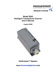
9146 User's Manual NetScanner™ 9146R NetScanner™ 9146T Table of Contents Introduction.......................................................................................... 4 The NetScanner Family...................................................................... 4 NetScanner Instrument Features....................................................... 4 NetScanner 9146................................................................................ 4 Operational Theory................................................................................5 Overview............................................................................................ 5 System Check.................................................................................... 5 Data Acquisition................................................................................ 5 Channel Monitoring........................................................................... 7 Best Practices........................................................................................ 8 Standard Configuration..................................................................... 8 Transducer Attachment..................................................................... 9 Standard Mounting........................................................................... 13 Environment..................................................................................... 13 Application Development.................................................................. 15 Details.................................................................................................. 15 Electrical.......................................................................................... 15 Mounting.......................................................................................... 15 Environmental.................................................................................. 15 Network.............................................................................................16 Application Development.................................................................. 16 Operations and Testing..................................................................... 18 Safety................................................................................................18 Company & Product Information.......................................................... 18 About Measurement Specialties........................................................ 18 Warranty........................................................................................... 19 Technical Support.............................................................................19 Item Return Procedure..................................................................... 19 Mounting Dimensions........................................................................... 20 Glossary................................................................................................ 21 9146 Users Manual Page 3 of 23 Introduction The NetScanner Family Dedicated to testing turbo machinery, the NetScanner Family of Instruments is a unique dataacquisition platform comprised of multiple units that can be networked to form a distributed intelligent system. These units The NetScanner family of instruments are highperformance microprocessorbased devices, each dedicated to measuring a specific parameter such as pneumatic pressures, liquid pressures, or temperatures. Ruggedized and splashproof, they can be used as standalone instruments or strategically located throughout a test facility to optimize measurement capability. They are accessed and networked through an Ethernet interface to the users host computer. The NetScanner Family of Instruments offers unparalleled flexibility and economy in configuring a data acquisition system tailored to the requirements of a specific test. NetScanner Instrument Features NetScanner instruments: • Operate on a single power supply and are easily configured via an Ethernet interface. • Use a standardized command interface, ensuring software compatibility and promoting code reuse. • Withstand environmental factors common in the industrial test applications such as; fluid spray, temperature extremes, acoustic noise and vibration. • Deliver precise, accurate measurements while operating under the most demanding conditions. NetScanner 9146 The NetScanner 9146 is available in two versions – NetScanner 9146T (Thermocouple) and NetScanner 9146R (RTD, Thermocouple, and Voltage). Both versions: • • • • • Perform continuous Open Circuit Detection of sensors. Are preconfigured with industry standard thermocouple and RTD coefficients. Can use custom lookup tables for nonstandard sensors. Can be set to output data in Kelvin, Fahrenheit, Celsius, Volts, or Ohms. Are easily calibrated. The 9146T interfaces with thermocouples, using 16 screw terminal. The screw terminal recess is protected by a gasketed cover. The cover and its fasteners are captive, reducing the possibility of FOD (Foreign Object Damage) to other machinery. The 9146R interfaces with sensors using Smart Connector Technology. Smart Connectors offer automatic transducer identification, hookup verification, and customized calibration coefficients for each channel. A total of 32 voltage inputs are available, two per channel. Each input can be assigned an independent lookup table. They are matched to a single sensor and store sensor specific data in embedded nonvolatile memory. The Thermocouple version of the Smart Connector also incorporates the reference junction, reference junction thermistor, and polarity verification and correction circuitry. 9146 Users Manual Page 4 of 23 Operational Theory Overview All of the models that comprise the NetScanner family of instruments operate in a similar manner. Built into each NetScanner unit is a server, to which a computer client connects using an Ethernet cable. Requests for information such as current status or data from transducers can be made of the server using software on the connected client computer. NetScanner Unified Startup Software (NUSS) is provided free of charged and is used to perform routine maintenance, such as calibration. System Check When power is applied, the instrument checks several subsystems for proper operation. These include: • • • • The operating memory (SRAM) A/D converter Nonvolatile storage (FLASH) Sensor coefficients If any of these tests fail, that status is indicated in the UDP discovery message, which can be seen using NUSS. Data Acquisition After proper operational status has been confirmed, data acquisition begins. • STEP 1 For thermocouples the instrument measures all reference junction (UTR) temperatures and then measures the voltage from each sensor in turn. For RTDs or other sensors the current through the sensor and the voltage across the sensor are measured almost simultaneously. • STEP 2 Data for all channels are acquired in sequence and the complete data set is converted from volts to the desired engineering units. • STEP 3 The data set is then placed in a current value table. • STEP 4 – The data is delivered to the host computer. Thermocouple Process Diagram Figure 1 9146 Users Manual Page 5 of 23 Operational Theory Continued Data Acquisition Continued RTD Process Diagram Figure 2 Dual Voltage Process Diagram Figure 3 When a client application such as NUSS establishes a TCP/IP connection to the NetScanner unit server, that application can immediately request that the current value table is transmitted. The operator can be assured that the data is only a few milliseconds old. 9146 Users Manual Page 6 of 23 Operational Theory Continued Channel Monitoring Thermocouples and RTDs are continuously monitored for an open circuit condition. In the 9146T and 9146R, after a channel is sampled, a small voltage is applied to the sensor. If the sensor is intact, that voltage is conducted directly to the ground return. If the sensor is open, no path exists for current to flow and the voltage is stored in a small capacitor placed across the transducer channel input. Each time the sensor is sampled, additional charge is injected into the capacitor until its value exceeds 55 mV. RTD failure is sensed by the lack of current flowing through the transducer at measurement time. The condition is indicated in the same manner in both instruments. The value for the faulty channel is set to a constant output within the stream of data. In all cases, the fault condition is sensed and indicated in less than 1 second. Open Sensor Detection Process Diagram Figure 4 9146 Users Manual Page 7 of 23 Best Practices Standard Configuration NetScanner instruments can be used individually or as part of a much larger multi parameter system. Every NetScanner unit uses the same power supply, Ethernet connection and cables. A typical configuration includes: • The NetScanner instrument itself. • An Interface Box for providing DC power, Ethernet communication, and hardware trigger. • A cable which connects the NetScanner instrument to the Interface Box. 9146R Standard Connections Figure 5 9146 Users Manual Page 8 of 23 Best Practices Continued Sensor Attachment The NetScanner 9146R Smart Connectors are constructed using standard LEMO® connectors. Smart Connectors are available from Measurement Specialties in both RTD and thermocouple versions. Standard LEMO® connectors may be purchased directly from LEMO® but will not include the Smart Connector internal circuit board. 9146R Sensor Attachment Smart Connector Figure 6 RTD Connections Figure 7 Thermocouple Connections Figure 8 9146 Users Manual Page 9 of 23 Best Practices Continued Sensor Attachment Continued 9146R Sensor Attachment Smart Connector Dual Voltage Connections Figure 9 mVDC Connections Figure 10 9146 Users Manual Page 10 of 23 Best Practices Continued Sensor Attachment Continued 9146R Sensor Attachment Smart Connector VDC or mVDC Connections Figure 11 9146 Users Manual Page 11 of 23 Best Practices Continued Sensor Attachment Continued The fasteners on the NetScanner 9146T are 832 binder head screws. Spade terminals appropriate for this application are available off the shelf from most major electrical suppliers. 9146T Sensor Attachment Thermocouple Connections Figure 12 The 9046S uses closedbarrel crimp terminals (available from Measurement Specialties), which are capable of retaining wire gauges between 24 and 18 (0.5 and 1.0 mm diameter). 9046S Sensor Attachment RTD / Resistance Connections Figure 13 Thermocouple Connections Figure 14 9146 Users Manual Page 12 of 23 Best Practices Continued Standard Mounting The NetScanner family of instruments can be mounted in any orientation. If the location is subject to vibration or shock, a standard shock mount kit should be used. The kit consists of 6 isolation mounts and a ground strap, which is connected to the instrument case and also connected to the mount point, ensuring electrical contact with the chassis or item under test. 9146 Shockmount Figure 15 Environment The NetScanner case is sealed against environmental contaminants. It is also coated with an epoxybased paint, which will protect the finish from chemical attack. Fluid spray and particulates will not affect the functionality or appearance of NetScanner. NetScanner 9146 is capable of operating over a temperature range of 30 to 70 degrees C. However, the compensated range (the range of temperature over which the reference junction is capable of resolving 0.1 degrees C change) is between 30 and 60 degrees C. Caution– For the NetScanner 9146T and NetScanner 9046S, or when using thermocoupletype Smart Connectors for the 9146R, the accuracy of thermocouple measurements will be reduced if the temperature of the reference junction exceeds 60 degrees C. If it is necessary to operate above this limit, active cooling of the instrument or Smart Connectors is required. NetScanner 9146 is designed to operate correctly while being subjected to vibration and acoustic levels found in proximity to operating turbomachinery . This instrument can withstand sound pressure levels up to 160 dB (std. Reference 2 x 10⁵ Pa) and 30g peak shock load. A full description of the vibration operating envelopes for 9146 is located in the data sheet. 9146 Users Manual Page 13 of 23 Best Practices Continued Network NetScanner utilizes both TCP/IP and UDP/IP for communication and automatic discovery of instruments. Be sure to use reliable Ethernet switches to connect these instruments with the host computer. Also, in order to assure reliable delivery of data, it is recommended that the number of nonNetScanner devices on the data network be kept to a minimum. Tip – In general, any Ethernet switch capable of 10BaseT or 100BaseT will be usable with NetScanner instruments. NetScanner takes advantage of Ethernets inherent fault tolerance. Since each NetScanner instrument is a separate, autonomous device, a fault on one network segment is isolated from the remainder of the network. Instruments on the unaffected network segments will continue to acquire and output data without interruption. It is even possible to exchange one instrument for another without interrupting the operation of the data application. Network Connections with 90DB Figure 16 9146 Users Manual Page 14 of 23 Best Practices Continued Application Development The NetScanner family of instruments is designed to be easy to use, and developing a custom application for it is also straightforward. Although a variety of features and capabilities are available, data can be successfully acquired with only a small subset. NetScanner instruments use humanreadable commands for all functions. Those commands perform identical functions when sent to any NetScanner instrument. This feature promotes code reuse, reducing development time and associated cost. A software application that can connect to one NetScanner instrument will be able to connect to any NetScanner instrument. Tip – Measurement Specialties provides free example code that demonstrates various tasks, and Labview™ examples are also freely available. Details Electrical NetScanner instruments are completely selfcontained but they do require some additional accessories to function. Depending on your installation, you will need one of the following boxes: 9IFC (9 Interface) Box – Use this when your installation will involve only a single NetScanner instrument. It provides access to the input and output connections for power, communications and hardware trigger. 90DB (90 Distribution) Box – Use this when more than one NetScanner instrument will be networked together. It’s available in both 7 and 15instrument options. Mounting The NetScanner family of instruments can be mounted in any orientation. If the location is subject to vibration or shock, a standard shock mount kit should be used. The kit consists of 6 isolation mounts and a braided ground strap, which is connected to the instrument case and also connected to the mount point, ensuring electrical contact with the chassis or item under test. Environmental The NetScanner case is sealed against environmental contaminants. It is also coated with an epoxybased paint, which will protect the finish from chemical attack. Fluid spray and particulates will not affect the functionality or appearance of NetScanner. NetScanner 9146 is capable of operating over a temperature range of 30 to 70 degrees C. However, the compensated range (the range of temperature over which the reference junction is capable of resolving 0.1 degrees C change) is between 30 and 60 degrees C. Caution– For the NetScanner 9146T and NetScanner 9046S, or when using thermocoupletype Smart Connectors for the 9146R, the accuracy of thermocouple measurements will be reduced if the temperature of the reference junction exceeds 60 degrees C. If it is necessary to operate above this limit, active cooling of the instrument or Smart Connectors is required. 9146 Users Manual Page 15 of 23 Details Continued NetScanner 9146 is designed to operate correctly while being subjected to vibration and acoustic levels found in proximity to operating turbomachinery . This instrument can withstand sound pressure levels up to 160 dB (std. Reference 2 x 10⁵ Pa), 20g peak shock load for 9146R, and 30g peak shock load for 9146T. A full description of the vibration operating envelopes for 9146 is located in the Appendix. Network Protocols NetScanner uses TCP/IP and UDP/IP to communicate. Addresses NetScanner will be configured with a static IP Address when assembled. This address can be easily changed to conform to any network topology. Addressing is of type IPv4. NOTE – Internet Protocol version 6 is not supported. Interconnection Hardware Commercial, offtheshelf network switches can be used for interconnection of NetScanner instruments. Although there are some benefits to choosing “carrier grade” switches, such as traffic shaping or other IT requirements, they are not required for normal operation. Network Checklist 1. Firewall software must be configured to permit access to UDP Port 7001 to support automatic detection of NetScanner instruments. 2. The IP Address and Subnet Mask of NetScanner instruments must be compatible with the host computer/local network configuration. 3. The Link LED on NetScanner instruments must be lit, indicating a valid connection. 4. The Link LED on the facility Ethernet Switch to which the NetScanner instrument is connected must be lit, indicating a valid connection. Application Development Configuration In order to simplify application development, a NetScanner instrument can be automatically identified on the network and its status determined without requiring a user to input any information. NetScanner instruments transmit their identification and status via UDP in response to a broadcast command or when powered up. This status message includes all of the information a host application requires to establish a TCP/IP connection. 9146 Users Manual Page 16 of 23 Details Continued Acquisition Data acquisition is initiated with a single command. The instruments will begin streaming data at the rate for which they were configured. The data will continue being sent until an explicit stop command is sent to each instrument. NetScanner instruments retain individual transducer data within the nonvolatile storage of the transducer itself. After a TCP connection has been established the application developer can retrieve all transducer data and determine type, range, serial number and calibration status. Measurement Specialties has also implemented User Accessible Memory space within the transducer where additional information may be placed and retrieved. After extracting any required information from the instruments, a single command configures them to output data at the desired rate. There is no requirement that all instruments be configured to acquire data at the same rate. Some parameters change more slowly and do not require high update rates. Since the instruments are independent servers, they can source data at rates appropriate for their application. Synchronization When NetScanner instruments are configured to stream data, the data packets are acquired in response to either an internal timer event or an external Hardware Trigger event. Since the internal clocks will not be in phase with each other, applications that require determinism should synchronize the data using a TTL pulse. This signal is applied to the Hardware Trigger input of each instrument in parallel. When the trigger pulse is initiated, all instruments will acquire and output a data packet. One new data packet will be generated and emitted each time the trigger is applied. Application Development Checklist 1. All transducers must be connected to the instrument before power is applied. 2. Thermocouples used with the 9146T should be connected to the terminals using spade lugs to reduce the probability of broken conductors. 3. Using the crimp pins available from Measurement Specialties to attach transducers to the NetScanner 9046S will ensure proper fit and contact. 4. Prior to use, the NetScanner instrument must be powered up for a minimum of 1 hour to ensure accuracy. 5. Firewall applications on the host computer must permit access to UDP port 7001 for automatic detection of NetScanner instruments. 6. A TCP/IP connection must be established with the NetScanner instrument to permit configuration. 7. The NetScanner instrument should be configured to stream data to the host computer at the rate required. 8. A Hardware Trigger signal must be used to synchronize data acquisition between multiple instruments. 9146 Users Manual Page 17 of 23 Details Continued Operation and Testing Measurement Specialties provides the NetScanner Unified Startup Software (NUSS), application free of charge to all customers. NUSS provides the ability to immediately acquire data as well as to verify the performance of the instruments. It’s also used to test instruments during assembly and is an integral tool used by the Applications Department for worldwide customer support. NUSS can operate multiple NetScanner instruments simultaneously. It automates many of the tasks necessary for maintaining them. Functions available through NUSS include: • • • • Firmware update Calibration Functional testing Data acquisition. Safety This instrument is designed for use with temperature sensors in applications where the temperature can be dangerously high. Persons servicing this equipment or installing sensors should use appropriate safety procedures and protective equipment to prevent personal injury. Measurement Specialties recommends that all personnel working on or around this instrumentation wear safety glasses at all times. Company & Product Information About Measurement Specialties Measurement Specialties is a global designer and manufacturer of sensors and sensor based systems that measure pressure/force, position, vibration, temperature, humidity, and fluid properties. Our products are used as embedded devices by original equipment manufacturers (OEMs) or as standalone sensors for test and measurement to provide critical monitoring, feedback and control input. We are at the heart of many everyday products and provide a vital link to the physical world. Global Headquarters 1000 Lucas Way Hampton, VA 23666 United States +1 757 766 1500 +1 757 766 4297 Fax 9146 Users Manual Page 18 of 23 Warranty Measurement Specialties warrants NetScanner instruments to be free of defects in material and workmanship under normal use and service for one (1) year. Technical Support Knowledgeable personnel are available to provide assistance and troubleshooting Monday through Friday from 8:00 a.m. through 5:00 p.m. Eastern Time. Contact the Applications Support Group or the Customer Services Department at Measurement Specialties (+1 757 766 1500 or toll free +1 800 745 8008) if your NetScanner instrument is not operating properly or if you have questions concerning any of our products. Email assistance is available by contacting [email protected]. Item Return Procedure ATTN: MEASUREMENT SPECIALTIES REPAIR DEPARTMENT (7digit RMA number) Measurement Specialties 1000 Lucas Way Hampton, VA 23666 United States Measurement Specialties will return warranty items prepaid via UPS GROUND. If the customer desires another method of return shipment, Measurement Specialties will prepay and add the shipping charges to the repair bill. Incoming freight charges are the customer’s responsibility. The customer is also responsible for paying shipping charges to and from Measurement Specialties for any equipment not under warranty. All products covered under the Measurement Specialties warranty policy will be repaired at no charge. An analysis fee will be charged to quote the cost of repairing any item not under warranty. If, for any reason, the customer decides not to have the item repaired, the analysis fee will still be charged. If the quote is approved by the customer, the analysis fee will be waived. The quote for repair will be based on the Measurement Specialties flat rate for repair, calibration, and board replacement. When these prices do not apply, the quote will be based on an hourly labor rate plus parts. All replaced parts are warranted for 90 days from the date of shipment. The 90day warranty is strictly limited to parts replaced during the repair. 9146 Users Manual Page 19 of 23 Mounting Dimensions 9146T Dimensions 9146R Dimensions 9146 Users Manual Page 20 of 23 Glossary 9046S – See NetScanner 9082 Cable – A cable that connects a nonrackmounted NetScanner instrument to an interface such as a 9IFC, 90DB or the auxiliary connectors on the back of a 98RK1. 90DB – 90 Distribution Box: A hardware interface which provides power, distributes Hardware Trigger Signals, and distributes Ethernet communications to multiple NetScanner instruments. It can interface with either 7 or 15 NetScanner instruments. 9146R – See NetScanner 9146T – See NetScanner 98RK1 – 9816 Scanner Interface Rack: A hardware interface which provides power, distributes Hardware Trigger Signals, distributes Ethernet communications, and provides a pneumatic interface for 9816 NetScanner instruments. It can interface with up to 8 9816 rackmounted NetScanner instruments and an additional 3 nonrackmounted NetScanner instruments. 9IFC – 9 Interface: A hardware interface that connects Power, Hardware Trigger, and Ethernet communications to a single NetScanner instrument. 9SM 9 Shock Mount: See Shock Mount Kit Application – Refers to a program that executes within a computer. In this document it is specifically the program that communicates with a NetScanner instrument. Broadcast – Transmission of data to all hosts on a network. Within this document a broadcast implies sending a User Datagram Protocol (UDP) Auto Discovery message to all NetScanner instruments. Hardware Trigger – A TTL, 0 to 5V, 50% Duty Cycle, Square Wave used to synchronize data acquisition for multiple NetScanner instruments. IP Address – The Internet Protocol version 4 address assigned to and used by a NetScanner for communication over a Network. IT – Information Technology: Refers to the IT department, which is responsible for administering and maintaining a network in many organizations. 9146 Users Manual Page 21 of 23 Glossary Continued NetScanner – A family of independent, networkable data acquisition instruments as summarized in the following table: 9116 Contains 16 pressure transducers Used for Dry noncorrosive gas measurements 9816 Contains 16 pressure transducers Used for dry, noncorrosive gas measurements Mounted in a 98RK1 chassis supporting up to 8 individual 9816 units 903x Contains a single Precision transducer Used for Dry noncorrosive gas measurements Capable of supplying a precision output for calibration of other instruments 9022 Supports up to 12 – 940X allmedia transducers The 940X transducers are available on Absolute, Gauge, and Differential configurations 9146T Supports up to 16 Thermocouples of any type Accepts Custom lookup tables supporting both custom calibrations and nonstandard thermocouple types Withstands 30 G peak shock load 9146R Supports up to 16 temperature transducers Smart Connector Capability supports sensor location and calibration Any type of thermocouple and RTD is supported Accepts Custom lookup tables supporting both custom calibrations and nonstandard thermocouple types Withstands 20 G peak shock load 9046S Supports up to 16 transducers Any combination of RTD, Thermocouple, or voltage measurements NUSS – NetScanner Unified Startup Software: The application used by Measurement Specialties to test NetScanner instruments during assembly. This application is offered free to customers for test and calibration of NetScanner instruments. Reference Junction – A thermocouple which is used as a reference for a second thermocouple. 9X46 measures the reference junction temperature to a high degree of accuracy using a precision thermistor. 9146 Users Manual Page 22 of 23 Glossary Continued RTD – Resistive Temperature Device; a transducer which exploits the repeatable change of resistance in a material due to changing temperature. These devices are typically constructed of platinum or nickel. Shock Mount Kit – 9SM: An accessory kit used when a non rackmounted NetScanner instrument is mounted where it will be subjected to vibration and shock. Smart Connector – See Smart Connector Technology Smart Connector Technology – the integration of nonvolatile memory within a transducers connector. The Smart Connector retains all information relevant to the attached transducer, offering benefits such as: 1> Calibration and traceability of sensors a. Calibration due dates are retained with the sensor b. Custom coefficients stored within the connector are automatically used by the instrument 2> Sensor hookup verification a. A descriptive tag for the sensor location can be saved to the connector memory 3> Corrects for reverse thermocouple connections a. Manual repair of a mis wired thermocouple is not required. Stream – A sequence of data packets transmitted from a NetScanner. TCP – Transmission Control Protocol; a component of the Internet Protocol. This protocol defines a connection oriented communications channel between two hosts on a network. Thermocouple – A transducer consisting of two dissimilar metals coupled at a single sensing junction. UDP – User Datagram Protocol; a component of the Internet Protocol. This protocol defines a connectionless method for transmitting data on a Network. User Accessible Memory – 32 Kbytes of storage space in a NetScanner instrument’s nonvolatile memory which is made available to customers. This can be used for channel identification. 9146 Users Manual Page 23 of 23


