1
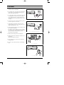
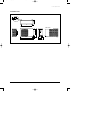
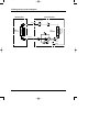
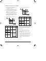
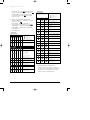
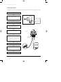
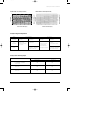
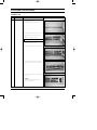
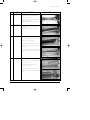
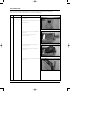
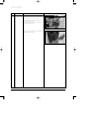
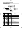
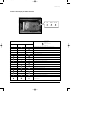
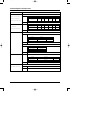
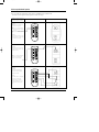
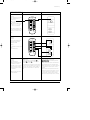
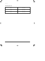
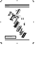
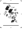
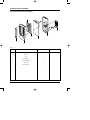
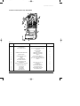
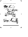
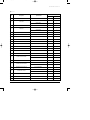
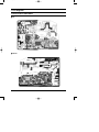
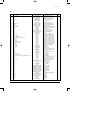
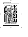
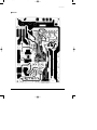
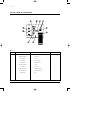
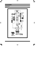
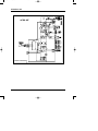
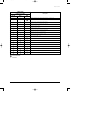
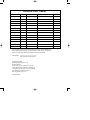
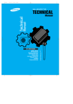
DB98_08728A(1)_CO
12/20/02 3:27 PM
Page 3
ROOM AIR CONDITIONER
INDOOR UNIT
OUTDOOR UNIT
SH12VCD
SH09VCD
SH12VCDX
SH09VCDX
SERVICE
Manual
AIR CONDITIONER
CONTENTS
1. Precautions
2. Product Specifications
3. Operating Instructions and
Installation
4. Disassembly and Reassembly
5. Troubleshooting
6. Exploded Views and Parts List
7. PCB Diagrams
8. Wiring Diagrams
DB98_08728A(1)_SM_1
12/20/02 3:24 PM
Page 1-1
1. Precautions
1. Warning: Prior to repair, disconnect the power
cord from the circuit breaker.
2. Use proper parts: Use only exact replacement
parts. (Also, we recommend replacing parts
rather than repairing them.)
3. Use the proper tools: Use the proper tools and
test equipment, and know how to use them.
Using defective tools or test equipment may
cause problems later-intermittent contact, for
example.
Fig. 1-1 Avoid Dangerous Contact
4. Power Cord: Prior to repair, check the power
cord and replace it if necessary.
5. Avoid using an extension cord, and avoid
tapping into a power cord. This practice may
result in malfunction or fire.
6. After completing repairs and reassembly, check
the insulation resistance.
Procedure: Prior to applying power, measure
the resistance between the power cord and the
ground terminal. The resistance must be
greater than 30 megaohms.
Fig. 1-2 No Tapping and No Extension Cords
7. Make sure that the grounds are adequate.
8. Make sure that the installation conditions are
satisfactory.
Relocate the unit if necessary.
9. Keep children away from the unit while it is
being repaired.
10. Be sure to clean the unit and its surrounding
area.
Fig. 1-3 No Kids Nearby!
Fig. 1-4 Clean the Unit
Samsung Electronics
1-1
DB98_08728A(1)_SM_1
12/20/02 3:24 PM
Page 1-2
MEMO
1-2
Samsung Electronics
DB98_08728A(1)_SM_1
12/20/02 3:24 PM
Page 2-1
2. Product Specifications
2-1 Table
Model(Indoor/Outdoor)
Item
Power Source
Capacity
Cooling
Performance
Energy efficiency ratio
Air Flow
Moisture removal
Noise level Indoor(Hi/Mid/Low)
Noise level Outdoor
Capacity
Energy efficiency ratio
Air Flow
Noise level Indoor(Hi/Mid/Low)
Noise level Outdoor
Available voltage range
Running amperes
Cooling Power input
Power factor
Running amperes
Electrical
Heating Power input
Rating
Power factor
Starting current
Fuse capacity
Power cord
Cable-connector
Type
Com- Model name
pressor Oil/Quantity
Safety devices
Model name
Indoor
Running capacitor
Fan
motor
Model name
Outdoor
Running capacitor
Narrow tube : Liquid
Refrigerant tube
Wide tube : Gas
Cooling
Capillary tube
Heating
Refrigerant to charge (R22)
Additional Refrigerant (R22)
Indoor unit : W x H x D
Dimension
Outdoor unit : W x H x D
Indoor unit
Weight
Outdoor unit
Heating
Remark : Test condition
Cooling test
Heating test
Samsung Electronics
ø-V-Hz
W
Btu/h
Btu/wh
m3/min
\/h
dBA
W
Btu/h
Btu/wh
m3/min
dBA
V
A
W
%
A
W
%
A
AxV
AxV
mm3 x G
CC
µF x VAC
µF x VAC
mmxMT
mmxMT
mm
mm
gr
gr/m
mm
mm
Kg
Kg
SH12VCD/SH12VCDX
SH09VCD/SH09VCDX
1-220 / 240-50
3510(2340~4100)
12000(8000~14000)
9.0(11~7.7)
7.8
1.9
39 / 37 / 35
52
3800(2550~4980)
13000(8700~17000)
9.3(11.9~7.5)
8.3
39 / 37 / 35
53
187~264
5.9(3.2~8.2), MAX12A↓
1330(720~1820)
97.1(96.3~96.5)
6.1(3.3~10.0), MAX12↓
1400(730~2260)
99.8(96.2~98.3)
12↓
3.15 x 250 / 20 x 250
15 x 250
1.5 x 4
Single Rotary
48A135RV2EL
SUN ISO4GSD-T / 410
204CT
AMPFS-022WTVA
1.2 x 450
AMASS-020WTVB
1.7 x 450
OD 6.35 x 5
OD 12.7 x 5
1-220 / 240-50
2630(1640~3010)
9000(5600~10300)
8.6(10.8~7.8)
6.5
1.5
38 / 36 / 34
52
3310(1900~4100)
11300(6500~14000)
9.8(12.0~9.1)
7.1
38 / 36 / 34
53
187~264
4.6(2.5~5.8), MAX12↓
1040(520~1315)
98.3(90.4~98.6)
5.2(2.6~6.7), MAX12↓
1152(545~1530)
94.5(90.4~99.3)
12↓
3.15 x 250 / 20 x 250
15 x 250
1.5 x 4
Single Rotary
44B092QV2EL
SUN ISO4GSD-T / 360
204CT
AMPFS-022WTVA
1.2 x 450
AMASS-020WTVB
1.7 x 450
OD 6.35 x 5
OD 9.52 x 5
1.7 x 800
ID1.5 x 1000
780
30
790 x 245 x 165
750 x 530 x 245
8
42
670
20
790 x 245 x 165
750 x 530 x 245
8
39
Indoor room
DB27˚C / WB19˚C
DB20˚C / - -
Remark
JAPAN SUN OIL
More 5m
Outdoor room
DB35˚C / WB24˚C
DB7˚C / WB6˚C
2-1
DB98_08728A(1)_SM_1
12/20/02 3:24 PM
Page 2-2
2-2 Dimensions
2-2-1 Indoor Unit
(Front view)
245
Air
in
790
165
Air out
115
(Remote control)
45
22
Installation plate
2-2
Samsung Electronics
DB98_08728A(1)_SM_1
12/20/02 3:24 PM
Page 2-3
P roduct Specifications
2-2-2 Outdoor Unit
256
10
10
600
(Front view)
Samsung Electronics
532
443
(Rear view)
720
145 55
765
245
2-3
DB98_08728A(1)_SM_1
12/20/02 3:24 PM
Page 2-4
2-3 Refrigerating Cycle Block Diagram
INDOOR UNIT
OUTDOOR UNIT
Capillary tube
T1
2-way valve
Heat
exchanger
(Evaporator)
Propeller fan
Cross fan
Liquid side
Heat
exchanger
(Condenser)
T2
Gas side
3-way valve
4-way valve
Cooling
Compressor
Heating
Gas leak check point
2-4
Samsung Electronics
DB98_08728A(1)_SM_1
12/20/02 3:24 PM
Page 2-5
3. Operating Instructions and Installation
3-1 Operating Instructions
3-1-1 The Feature of Key in remote controller
NO
FUNCTION OF KEY
FEATURE OF KEY
Power On/Off button to start and stop airconditioner or timer set up.
1
(UP)
Temp. up button. To increase the temperature by the pressing
the temperature button.
(DOWN)
Temp. down button. To decrease the temperature by the pressing
the temperature button.
2
3
Each time you press this button,
MODE is changed in the following order.
: Auto Mode
: Fan Only
: Cool Mode
: Heat Mode
: Dry Mode
Press
until the appearance. the air conditioner cools or heats
the room as quickly as possible.
After 30minutes, the airconditioner is reset automatically to the previous mode.
4
Press
until the appearance. the sleep timer can be used when
you are cooling or heating your room to switch the air conditioner off
automatically after a period of six hours.
5
6
Each time you press this button,
FAN SPEED is changed in the following order.
Adjust air flow vertically.
7
The ON Timer enables you to switch on the air conditioner automatically
after a given period of time that is from 30 minutes to 24 hours.
To cancel, press the
(Set/Cancel) button.
8
The Off Timer enables you to switch off the air conditioner automatically
after a given period of time that is from 30 minutes to 24 hours.
To cancel, press the
(Set/Cancel) button.
9
Samsung Electronics
To select the 5 way function with the remote control, press the (5 way)
button one or more times until the desired mode is selected.
Each time you press the (5 way) button, each 5 way indicator on the indoor unit lights
up in order.
3-1
DB98_08728A(1)_SM_1
12/20/02 3:24 PM
Page 2-6
Operating Instructions and Installation
3-1-2 Name & Function of Key in remote controller
1. AUTO CHANGEOVER FUNCTION :
*To operate in the “Auto change over” mode,
set the MODE on “AUTO”.
*According to the outdoor and indoor temperatures while starting the operation, one of
the modes from the cooling, dehumidifying
and heating is selected automatically to
operate.
*The operation mode shall be set again if the
other condition different from that of the
operating conditions(cooling, heating, dehumidifying mode) is kept for 60 minutes during the change-over operation.
1) Mode selection for operation start
2) Mode selection during the operation
Outdoor
temperature
Indoor
temperature
Operation
Wind
Set temperature
type
volume
31˚C over
29˚C over 31˚C less
21˚C over 27˚C over 29˚C less Cooling
25˚C over 27˚C less
21˚C over
25˚C less
18˚C over
21˚C less
All area
18˚C less
27˚C over
18˚C less
Outdoor
temperature
Indoor
temperature
Operation
type
Set temperature
31˚C over
29˚C over 31˚C less
21˚C over 27˚C over 29˚C less Cooling
25˚C over 27˚C less
21˚C over
25˚C less
18˚C over
21˚C less
23˚C over
18˚C less
27˚C over
18˚C over
21˚C less
23˚C less
18˚C less
27˚C less
3-2
Wind
volume
28˚C
27˚C
Automatic
26˚C
25˚C
to be set automatically by controller
Dehumid- according to the
fying indoor temperature at the operation start.
to be set automatically by controller
according to the
indoor temperaHeating ture at the operation start.
23˚C
21˚C
28˚C
27˚C
Automatic
26˚C
25˚C
to be set automatically by controller
Dehumid- according to the
fying indoor temperature at the operation start.
21˚C over 23˚C less Heating
21˚C less
23˚C
21˚C
2. COOL MODE : The unit operates according to the difference between the setting
and room temperature.(setting Temp.:
18°C~30°C)
3. HEAT MODE : The unit operates according to the difference between the setting
and room temperature.(setting Temp.:
16°C~30°C)
*Prevention against cold wind : For about
3~5 minutes after initial operation (thermo
control or “de-ice”), the indoor fan will
either not operate or operate very slowly,
then switch to the selected fan speed. This
period is to allow the indoor unit's heatexchanger to prewarm until emitting
warm air.
Samsung Electronics
DB98_08728A(1)_SM_1
12/20/02 3:24 PM
Page 3-1
Operating Instructions and Installation
*High temperature release function : The
outdoor unit and compressor ON/OFF is
controlled for safety operation when heat
exchanger of indoor unit is over heated.
*De-ice : Deicing operation is controlled
by outdoor unit's heat exchanger temperature and accumulating time of compressor's operation.
De-ice ends by sensing of the processing
time by de-ice Condition.
4. DRY MODE :
*According to the difference between the
set temperature (Ts) and indoor temperature (Tr), the operation frequency of compressor is controlled as each area.
(Cooling area/COMPor ON/OFF
area/Monitoring area)
➟ Cooling area : same as the cool mode
➟ COMPor ON/OFF area : repeat of
COMPor frequency 36[Hz] for 4 minutes
operation/0[Hz](off) for 6 minutes
➟ Monitoring area : COMPor off.
5. TURBO MODE : This mode is available in
AUTO, COOL, HEAT, DRY, FAN MODE.
When this button is pressed at first, the
air conditioner is operated in “powerful”
state for 30 minutes regardless of the set
temperature, room temperature.
When this button is pressed again, or
when the operating time is 30 minutes,
turbo operation mode is canceled and
returned to the previous mode.
*But, if you press the TURBO button in
DRY or FAN mode, it is changed into
AUTO mode automatically.
6. SLEEP MODE : Sleep mode is available
only in COOL or HEAT mode.
The operation will stop after 6 hours.
*In COOL mode : The setting temperature
is automatically raised by 1°C each 1hour
When the temperature has been raised by
total of 2°C, that temperature is maintained.
Samsung Electronics
*In HEAT mode : The setting temperature
is automatically droped by 1°C each
1hour.
When the temperature has been droped by
total of 2°C, that temperature is maintained.
7. FAN SPEED : Manual (3 step), Auto (4
step)
Fan speed automatically varies depending
on the difference between setting and the
room temperature.
8. COMPULSORY OPERATION :
For operating the air conditioner without
the remote controller, the tact key in
indoor unit can be used.
When started with this key, the mode is
set on “AUTO”.
The operating is the same function as
AUTO MODE in the remote controller.
Each time you press this key, 5WAY
function is changed in the following order;
STD(standard) ➝ NATURE ➝
POWER(High-speed) ➝ Saving(PowerSaving) ➝ SILENCE
❊ STD(standard)(
) : General operation
Mode
❊ NATURE(
) : The unit is operated
according to health
pattern control
❊ POWER(
) : The unit is operated in
powerful state
❊ SAVING(
) : The unit is operated in
power saving state
❊ SILENCE(
) : The unit is operated
quitely
Each mode has Auto(Cool or Heat) operation
designed in advance.
9. SWING : BLADE-H is rotated vertically by
the stepping motor.
*Memory louver : When ON/OFF button
is pressed at stop state, the BLADE-H
returns to its original location which is
operating state before stop.
3-3
DB98_08728A(1)_SM_1
12/20/02 3:24 PM
Page 3-2
Operating Instructions and Installation
*Swing Set : Press the
button under the
remote control is displayed on LCD the
and the blades move up and down. If the
one more time press the
button, blade
location is stop.
Outdoor unit
Description
LAMP of inverter PBA
Yellow
10. 24-Hour ON/OFF Real Setting Timer. :
The air conditioner is turned ON at a specified time using
.
OFF TIMER : The air Conditioner is
turned OFF at a specified time using
.
*ON TIMER : Only timer LED lights on.
*OFF TIMER : Both timer and operation
LED lights on.
Blue
Red
X
X
X
X
X
X
X
X
Trouble of option setting
X
Indoor unit
TIMER STD NATURE POWER SAVING SILENCE
X
X
X
X
X
X
X
X
X
X
X
X
X
X
3-4
X
X
X
X
X
X
X
X
X
X
X
X
X
X
X
X
X
X
X
X
X
X
X
X
X
X
X
X
X
X
Description
: Lamp on
: Lamp flickering
X : Lamp off
Indoor unit room temperature
sensor error(open or short)
Indoor unit heat exchanger temperature sensor error(open or
short)
Indoor fan motor mal function
EEPROM error
option error
Outdoor unit temperature sensor
error (open or short)
- outdoor temp-sensor
- deice temp-sensor
- OLP temp-sensor
- discharge temp-sensor
- heatsink temp-sensor
Abnormal communication
(Indoor - Outdoor unit)
Abnormal increase of operation
current
Abnormal increase of discharge
and OLP temperature
Over current of IPM circuit
Trouble of the PTC circuit of the
outdoor
Trouble of AC current
sensor(open/short) and Leakage
of refrigerant (R-22)
Normal operation and communication (Indoor-Outdoor unit)
Abnormal communication
(Indoor-Outdoor unit)
Trouble of the control power of
the outdoor
Abnormal communication
(Sub-Main micom)
No zero-crossing signal
11. SELF Diagnosis
LAMP of Display Monitor
: Lamp on
: Lamp flickering
X : Lamp off
X
X
Abnormal increase of discharge
temperature
Abnormal increase of OLP temperature
Abnormal increase of operation
current
Over current of IPM circuit
X
Over voltage of IPM circuit
X
Over voltage and current of PFC
circuit
Trouble of DC link voltage circuit
X
X
Trouble of discharge temp-sensor
(open/short)
Trouble of outdoor temp-sensor
(open/short)
Trouble of de-ice temp-sensor
(open/short)
Trouble of OLP temp-sensor
(open/short)
Trouble of AC current sensor
(open/short) and Leakage of
refrigerant(R-22)
12. BUZZER SOUND : Whenever the
ON/OFF button is pressed or whenever
change occurs to the condition which is set
up or select, the compulsory operation
mode, buzzer is sounded "beep".
Samsung Electronics
DB98_08728A(1)_SM_1
12/20/02 3:24 PM
Page 3-3
3-2 Installation
3-2-1 Selecting Area for Installation
Select an area for installation that is suitable to the customer's needs.
3-2-1(a) Indoor Unit
1. Make sure that you install the indoor unit
in an area providing good ventilation. It
must not be blocked by an obstacle affecting the airflow near the air inlet and the
air outlet.
2. Make sure that you install the indoor unit
in an area allowing good air handling and
endurance of vibration of the indoor unit.
3. Make sure that you install the indoor unit
in an area where there is no source of heat
or vapor nearby.
4. Make sure that you install the indoor unit
in an area from which hot or cool air is
spread evenly in a room.
5. Make sure that you install the indoor unit
in an area away from TVs, audio units,
cordless phones, fluorescent lighting fixtures and other electrical appliances (at
least 1 meter).
(Fix the unit firmly if it is mounted in a
high place.)
3. Make sure that you install the outdoor
unit in area providing good ventilation
and which is not dusty. It must not be
blocked by any obstacle affecting the airflow near the air inlet and the air outlet.
4. Make sure that you install the outdoor
unit in area free from animals or plants.
5. Make sure that you install the outdoor
unit in area not blocking the traffic.
6. Make sure that you install the outdoor
unit in area easy to drain condensed water
from the indoor unit.
7. Make sure that you install the outdoor
unit in area which provides easy connection
within the maximum allowable length of a
coolant pipe(15 meters).
Note
1. Add 20 grams of refrigerant (R-22) for every 1 meter
if the pipe length exceeds the standard pipe length
of 5 meters.
2. Maintain a height between the indoor and outdoor
units.
6. Make sure that you install the indoor unit
in an area which provides easy pipe connection with the outdoor unit, and easy
drainage for condensed water.
8. Make sure that you install the outdoor
unit in an area which is large enough to
accommodate the measurements.
7. Make sure that you install the indoor unit
in an area which is large enough to accomodate the measurements shown in figure
on the next page.
3-2-1(c) Remote Control Unit
3-2-1(b) Outdoor Unit
1. Make sure that you install the outdoor
unit in area not exposed to the rain or
direct sun light.
(Install a separate sunblind if exposed to
direct sun light.)
2. Make sure that you install the outdoor
unit in area allowing good air moment,
not amplifying noise or vibration, especially to avoid disturbing neighbours.
1. Make sure that you install the remote control unit in an area free from obstacles
such as curtains etc, which may block signals from the remote control unit.
2. Make sure that you install the remote control unit in an area not exposed to
direct sunlight, and where there is no
source of heat.
3. Make sure that you install the remote control unit in an area away from TVs, audio
units, cordless phones, fluorescent lighting
fixtures and other electrical appliances (at
least 1 meter).
Caution
It is harmful to the air conditioner if it is used in the following environments: greasy areas (including areas near
machines), salty areas such as coast areas, areas where sulfuric gas is present such as hot spring areas. Contact your
dealer for advice.
Samsung Electronics
3-5
DB98_08728A(1)_SM_1
12/20/02 3:24 PM
Page 3-4
Operating Instructions and Installation
3-2-2(a) Refrigerant Refill
• Refill an air-conditioner with refrigerant when refrigerant has been leaked at installing or using.
1. Purge air(for new installation only).
2. Turn the 3-way valve clockwise to close,
connect the pressure gauge(low
pressure side) to the service valve, and
open the 3-way valve again.
Press this ON/OFF
Switch for 5sec.
And then the
Airconditioner
operating on rating
speed.
3. Connect the tank to refill with Refrigerant
4. Set the unit to Low pressure checking mode.
* Press the ON/OFF switch for 5 second.
*All lamps blink on the indoor unit.
Suspension hook
5. Check the pressure indicated by the
pressure gauge(low pressure side).
* Refer to Low pressure graph.
High
pressure
gauge
Compound
gauge
Hand
wheel
6. Open the refrigerant tank and fill with refrigerant until the rated pressure is reached.
* It is recommended not to pour the
refrigerant in too quickly, but gradually
while operating a pressure valve.
Finger tight
fittings
For mounting
other and of
hose when
not in use
Connected to
high pressure
side
Charging
line
7. Stop operation of the air conditioner.
R-22
8. Close the 3-way valve, disconnect the
pressure gauge, and open the 3-way
valve again.
9. Close the cap of each valve.
3-6
Samsung Electronics
DB98_08728A(1)_SM_1
12/20/02 3:25 PM
Page 3-5
Operating Instructions and Installation
• MODEL NAME : SH09VCD(SH09VCDX)
• MODEL NAME : SH12VCD(SH12VCDX)
6.5
5
4.5
4
3.5
20
25
30
35
40
6
5.5
5
4.5
4
45
20
Outdoor inlet air DB temp.(˚C)
25
30
35
40
Indoor Inlet air DB temp.(˚C)
5.5
32.4
30.6
28.8
27.0
24.0
21.5
6.5
Low Pressure
Low Pressure
6
Indoor Inlet air DB temp.(˚C)
7
32.4
30.6
28.8
27.0
24.0
21.5
45
Outdoor inlet air DB temp.(˚C)
3-2-2(b) Refrigerant Adjustment
Class
For installation
Connection
Pipe Length
5m
(standard)
Air-Purge
Method
Refrigerant
Adjustment
Refer to the
detailed Air-Purge
Procedure
Unnecessary
For service
Air-Purge
Method
Add 20g of refrigerant
(R-22) for every 1m.
6~15m
Purge air using a
vaccum pump
or an additional
refrigerant cylinder.
Refrigerant
Quantity
refer to
specification sheet
Add 20g of refrigerant
(R-22) for every 1m.
3-2-2(c) Flare unt fixing torque
Outter diameter
Torque (kg-cm)
Fixing Torque
Final Torque
ø 6.35 (9000Btu, 12000Btu)
(Liquid Side)
160
200
ø 9.52 (9000Btu)
(Gas Side)
300
350
ø 12.7 (12000Btu)
(Gas Side)
500
550
Samsung Electronics
3-7
DB98_08728A(1)_SM_1
12/20/02 3:25 PM
Page 3-6
4. Disassembly and Reassembly
Stop operation of the air conditioner and remove the power cord before repairing the unit.
4-1 Indoor Unit
No
1
Parts
Front Grille
Procedure
Remark
1) Stop the air conditioner operation and
block the main power.
2) Seperate tape of front panel upper.
3) Contract the second finger to the left, and
right handle and pull to open the inlet
grille.
4) Take the left and right filter out.
*Taking off the deodorizing filter.
5) Loosen one of the right fixing screw and
seperate the terminal cover.
6) Loosen three fixing screws of front grille.
7) Pull the upper left and right of discharge
softly for the outside cover to be pulled
out.
8) Pull softly the lower part of discharge and
push it up.
Caution;
Assemble the front panel and fix the
hooks of left and right.
4-1
Samsung Electronics
DB98_08728A(1)_SM_1
12/20/02 3:25 PM
Page 3-7
Disassembly and Reassembly
No
Parts
Procedure
2
Ass’y Tray Drain.
1) Do “1”above
2) Take all the connector of PCB upper side
out.
(Inclusion Power cord)
3) Separate the outdoor unit connection wire
from the terminal block.
4) If pulling the Main PCB up. it will be taken
out.
3
Electrical Parts
(Main PCB)
1) Do “1”, “2” above
Separate the drain hose from the extension
drain hose.
2) Pull tray drain out from the back body.
4
Heat Exchanger
1) Do “1” and “2”, “3” above
Remark
2) Loosen two fixing earth screws of right side.
3) Separate the connection pipe.
4) Separate the holder pipe at the rearside.
5) Loosen the three fixing screws of right and
left side.
6) Lifting the heat exchanger up a little to push
the up side for separation from the indoor
unit.
5
Fan Motor and
Cross Fan
1) Do “1”, “2”, ”3”, “4” above.
2) Loosen the fixing two screws and separate
the motor holder.
3) Loosen the fixing screw of fan motor.
(By use of M3 wrench)
4) Separate the fan motor from the fan.
5) Separate the fan from the left holder bearing.
Samsung Electronics
4-2
DB98_08728A(1)_SM_1
12/20/02 3:25 PM
Page 3-8
4-2 Outdoor Unit
Take care of the electrical shock by contact on the charging parts before the discharge
after power off. (If takes approximately 2 minutes to discharge.)
No
1
Parts
Procedure
Remark
Common Work 1) Loosen the fixing screw and separate the
&
Cover-Valve.
Ass’y-control Out
2) Separate the Cable-Connector Wire from the
Terminal-Block.
3) Loosen five fixing screws and separate the
Cabi-Upper.
4) Loosen five fixing screws from the
Ass’y-Control Out.
5) Separate the Terminal-Housing from the
Ass’y-Control Out.
6) Separate the Ass’y-Control Out from the
outdoor unit.
7) Loosen seven fixing screws and separate the
Cabi-Side.
4-3
Samsung Electronics
DB98_08728A(1)_SM_1
12/20/02 3:25 PM
Page 3-9
Disassembly and Reassembly
No
Parts
2
Fan-Motor
Procedure
Remark
1) Loosen Four fixing screw of the GuardFan.
2) Remove the nut flange (Turn to the right to
remove, as it is a left hand screw)
3) Separate the fan.
4) Loosen four fixing screws to separate the
motor.
3
Heat Exchanger
Samsung Electronics
1) Do “1” above.
2) Loosen three fixing screws of Ass’y-Frame
and Partition.
3) Disassemble the inlet and outlet pipe by
welding.
4) Separate the heat exchanger.
4-4
DB98_08728A(1)_SM_1
12/20/02 3:25 PM
Page 3-10
Disassembly and Reassembly
No
Parts
Procedure
4
Compressor
1) Do “1” above.
2) Open the terminal cover of compressor and
unscrew the connection terminal.
3) Disassemble the inlet and outlet pipe of
compressor by welding.
4) Disassemble the inlet and outlet pipe of
condenser by welding.
Remark
5) Loosen the three bolts of the lower part.
6) Separate the compressor.
4-5
Samsung Electronics
DB98_08728A(1)_SM_1
12/20/02 3:25 PM
Page 3-11
5. Troubleshooting
Since the inverter air conditioner is equipped with Electrical control circuits at both Indoor &
outdoor unit, the trouble shooting shall be performed according to the error mode.
Inside the controller of the outdoor unit (inverter), the large capacity of electrolytic condenser
so that it takes the time to discharge after the power off since the electrical charge remains
(the charging voltage DC 340V).
Take care of the electrical shock by contact on the charging part before the discharge after the
power off. (It takes approximately 2 minutes to discharge).
5-1 Basic items for trouble shooting
1) Is the power source proper?
The power source shall be in the range of the rated voltage ±10%. If it is out of this range, it
may cause the abnormal operation.
2) Is the connection made between the indoor and outdoor unit?
The connection between indoor and outdoor unit shall be performed with 4 wire. (connection
cable of indoor and outdoor unit + ground wire).
3) The phenomena as follows are not out of order.
NO
Phenomena
1 The operation is not done.
Cause and reason
Is the power off or the power unplugged?
Does it stop because it is the completion time?
• Unplug and plug again the power source for 2 minutes.
•
•
2 The wind comes out but the
heating/cooling is not
performed.
•
3 The remote controller does
not operate.
•
4 The wind volume is not
adjusted.
•
5 The temperature is not set.
•
Is the filter clogged with dust or dirty?
• Is there any direct light on the outdoor unit or any obstacle against it?
• Is the selected temperature too high? Lower the selected temperature lower than the
current one (during cooling).
• Is the selected temperature too low? Raise the desired temperature than the
current one (during heating).
• Is the “Fan only Mode” operation?
Is the battery run out?
Is the battery inserted in the wrong way(+, -)?
• Is the detection part of the indoor unit blocked?
• Does it interfered with the radio of neon sign?
•
Is the operation selected among one of Auto / Dry / Turbo / Sleeping?
• The temperature setting is not required since the wind volume set automatically.
• Check again at the state of Cooling / Fan only / Heating.
Is the operation selected among the Dry / Turbo / Sleeping / Fan only Mode.
Since the temperature is automatically set, the temperature setting is not required.
• Check again at the cooling/heating state.
• The standard temperature ±2˚C during the automatic operation.
•
6 The operation lamp continues
to be flickering.
•
7 The immediate operation
starts without control of
remote controller when
plugged
•
Samsung Electronics
Push the Operation / Stop button.
• Unplug and plug the power source.
It is the case that the auto restart function works.
# Auto restart function is the convenient function where the operation state is memorized
in the Memory IC during the blackout and the operation restarts when the power comes
back.
5-1
DB98_08728A(1)_SM_1
12/20/02 3:25 PM
Page 3-12
5-2 The first determination method of troubled part
5-2-1 Error mode display of indoor unit
POWER indicator
NATURE indicator
STANDARD indicator
Remote Control
Sensor
On/Off & 5 Way
Selection button
TIMER indicator
SILENCE indicator
SAVING indicator
LAMP of Display Monitor
TIMER
X
Description
STD
NATURE
POWER
SAVING
SILENCE
X
X
X
X
X
X
X
X
X
X
X
X
X
X
X
: LAMP ON
: LAMP FLICKERING
X : LAMP OFF
Indoor unit room temperature sensor error(open or short)
Indoor unit heat exchanger temperature sensor error
(open or short)
Indoor fan motor mal function
EEPROM error
Option error
Outdoor unit temperature sensor error(open or short)
- outdoor temp-sensor
X
X
X
X
- deice temp-sensor
- OLP temp- sensor
- discharge temp-sensor
- heatsink temp-sensor
X
X
X
X
X
X
X
X
5-2
X
X
X
X
X
Abnormal communication (Indoor - Outdoor unit)
X
X
\Abnormal increase of operation current
X
X
Abnormal increase of discharge and OLP temperature
X
X
Over current of IPM circuit
X
X
Trouble of the PTC circuit of the outdoor
X
X
Trouble of AC current sensor (open/short) and Leakage of
refrigerant(R-22)
Samsung Electronics
DB98_08728A(1)_SM_1
12/20/02 3:25 PM
Page 3-13
Troubleshooting
5-2-2 Error mode display of outdoor unit board
GREEN
GREEN
YELLOW
LED3
LED2
LED1
Description
LAMP of inverter PBA
YELLOW
RED
: LAMP ON
: LAMP FLICKERING
X : LAMP OFF
RED
Normal operation and communication (Indoor-Outdoor unit)
X
X
X
X
X
X
Abnormal communication(Indoor-Outdoor unit)
X
Trouble of the control power of the outdoor
X
Abnormal communication (Sub-Main micom)
No zero-crossing signal
X
Trouble of option setting
X
Abnormal increase of discharge temperature
Abnormal increase of OLP temperature
X
X
Abnormal increase of operation current
Over current of IPM circuit
X
Over voltage of IPM circuit
X
Over voltage and current of PFC circuit
Trouble of DC link voltage circuit
X
X
Trouble of discharge temp-sensor(open/short)
Trouble of outdoor temp-sensor(open/short)
Trouble of deice temp-sensor(open/short)
Trouble of OLP temp-sensor(open/short)
Trouble of AC current sensor(open/short) and Leakage of
refrigerant(R-22)
Samsung Electronics
5-3
DB98_08728A(1)_SM_1
12/20/02 3:25 PM
Page 3-14
5-3 Sequence of trouble shooting for inverter aircon
OPERATION START
• The indoor unit does not work even
though the power is plugged.
•There is no sound “DING”
•The lamp is not on the display.
The indoor unit does not work when
operated by the remocon.
Check the indoor unit control board. (5-3-1)
Checking the Remocon. (5-3-2)
Check the control board and the display board
of indoor unit.(5-3-2)
The lamp of the indoor display is flickering and the indoor unit stops several
minutes after the indoor unit starts.
Timer lamp(
) flickering
Standard(
), Timer(
) lamp flickering
Nature(
) lamp flickering
Timer(
), Nature(
) lamp flickering
Check the error mode by confirming the lamp
flickering of indoor unit display.
→ Check of the indoor temperature sensor (5-3-3)
→ Check of the indoor heat exchanger (5-3-3)
→ Check of indoor unit fan motor (5-3-4)
Check the indoor unit
→ Check the lines of the indoor and outdoor
communication (5-3-5)
Check of the
Communication line
) lamp flickering → Check of the outdoor unit temperature sensor
: Discharge temperature sensor (5-3-6)
: Comp top OLP temperature sensor (5-3-6)
: Deice temperature sensor (5-3-7)
: Outdoor temperature sensor (5-3-7)
POWER(
) flickering
→ Check of the abnormal increase protection
of the operation Current (5-3-8)
Timer(
), POWER(
) lamp
→ Check of the instantaneous over-current protection
flickering
mode of IPM circuit (5-3-9)
Nature(
), POWER lamp(
)
→ Check the abnormal increase of the comp
flickering
discharge gas temperature and OLP protection
mode.(5-3-10)
Standard(
5-4
), Nature (
Check of the Outdoor unit
Samsung Electronics
DB98_08728A(1)_SM_1
12/20/02 3:25 PM
Page 3-15
Troubleshooting
5-3-1 Check of indoor unit control board
Unplug the power cord and plug it after 5 seconds.
Press the on/off switch located in indoor unit inside to operate the air conditioner.
•If the air conditioner operates, check the remocon and indoor unit display board.
•If the air conditioner does not operate, check according to the sequence of the followings:
Check sequence of indoor unit control board
Step 1 : Check whether two wires of power cord (Sky-blue, brown) are connected correctly to
the terminal block.
•Sky -blue : connected to “N”
•Brown : connected to “L”
Step 2: Check whether the wire connected to the terminal block is connected correctly to the
control board.
(Control board)
(Terminal block)
JN
RY71
RY71
JC
SKY-BLU
N
L
1
2
BRN
ORG
BLK
SKY-BLU
(N1)
Step 3 : Check whether the fuse (F701)(F702) on the control board is normal. (5
[A]/250[V]:F701) (1[A]/250[V] : F702)
• If the fuse is broken, replace it with the new one.
Step 4 : check the output of SMPS on the control board.
• Input power AC187~AC264V—-IC 02 Input: DC 12V
IC 02 Output : DC 5V
5-3-2 Display board and remocon check of indoor unit
Check whether the connection wire of Display board is correctly connected to CN91
connector.
Check the voltage of remocon battery. - the voltage of one battery shall be higher than about
1.4 V, and then the remocon operates normally.
Check whether the neon sign is on and the 3 wave long fluorescent lamp is on around the
indoor unit. - After putting all lamps of the indoor out and then operate it by remocon. If it
operates with the remocon, it is the abnormality due to the interference from the light of
lamps. (Aircon unit is normal).
5-3-3 Check the indoor temperature sensor and indoor heat exchanger temperature sensor.
Take out the thermistor connected to the connector (CN41) of control board of indoor unit
and measure the resistance between two wires and if it is same as follows: it is normal but if
not, replace it.
Ambient temperature
(°C)
15°C
20°C
25°C
30°C
35°C
40°C
Resistance of
thermistor [KΩ]
14.68
12.09
10
8.31
6.94
5.83
Samsung Electronics
5-5
DB98_08728A(1)_SM_1
12/20/02 3:25 PM
Page 3-16
Troubleshooting
5-3-4 Check of indoor unit fan motor
Check whether the wire of fan motor is connected to the connector of control board (CN42,
CN71) of indoor unit.
Check whether the error mode displays after the strong revolution for approximately 15
seconds since aircon is on.
→ In case the error mode displays after the fan motor is rotating for 15 seconds → Defect of
HALL IC of fan motor and Control board
→ In case that the error mode displays without running of fan motor after 15 seconds. →
Operate with the pin of SSR(SS71) short of indoor unit control board and then if the fan
motor does not run, it is the fan motor defect.
If it rotates, it is the defect of control board (SS71, IC05, IC04).
5-3-5 Check of communication line between the indoor unit and outdoor unit
(Communication error mode)
1) Check of connection
Check whether the cable wire connecting the indoor unit with outdoor unit is correctly
connected to the (N1), 1, 2 terminal. (If the wire is connected reversely, the communication
error occurs)
If the cable connecting the indoor unit and outdoor unit is longer than 20m, error mode
occurs (shorten the cable length).
(Check of indoor unit)
Check whether the connection wire of the terminal block and control board of indoor unit is
correct.
(Control board)
JN
RY71
RY71
JC
(Terminal block)
SKY-BLU
SKY-BLU
N
L
1
2
BRN
ORG
BLK
(N1)
(Check of outdoor unit)
Check whether the connection wire of the terminal block and control board of outdoor unit is
correct.
(Control board)
#1 of CN31
N
L
(Terminal block)
BLK
SKY-BLU
BRN
2
(N1)
1
2) Check of power supply to the outdoor unit
After operation of aircon, select the turbo mode and approximately 3minutes later, check
whether the red color lamp of control board (to be seen if the top cover of outdoor unit) is on.
→ If the red lamp (LED 3) is not on, check the power part of control board of outdoor unit.
♦Check the connection of reactor.
→ If the red lamp (LED3) is on and green lamp is flickering, it is normal.
5-6
Samsung Electronics
DB98_08728A(1)_SM_1
12/20/02 3:25 PM
Page 3-17
Troubleshooting
5-3-6 Check of discharge temperature sensor and comp top OLP temperature sensor.
Connector of outdoor unit control board
(PIN#3,4 of CN51 - discharge temperature sensor), (PIN#1,2 of CN52-OLP Temperature
sensor)
Measure the resistance between two wires and if it is same as follows, it is normal but if not,
replace.
Ambient temperature
(°C)
Resistance of
thermistor [KΩ]
0°C
10°C
20°C
30°C
40°C
50°C
553
362
242
166
165
82
5-3-7 Check the deice temperature sensor and outdoor temperature sensor
Connector of outdoor unit control board
(PIN#1,2 of CN51 - outdoor temperature sensor),(PIN#3,4 of CN52-deice Temperature sensor)
Measure the resistance between two wires and if it is same as follows, it is normal but if not,
replace it.
Ambient temperature
(°C)
Resistance of
thermistor [KΩ]
15°C
20°C
25°C
30°C
35°C
40°C
14.68
12.09
10
8.31
6.94
5.83
5-3-8 Check of operation current abnormal increase mode
The operation abnormal current mode is the protection control for the safe operation by
detecting the operation current of inverter aircon by the current sensor on the control board.
If the operation current abnormal increase occurs,
♦The ventilation is not good because the outdoor unit is installed wrong (the ambient temperature is higher than 50 °C)
→ Reinstall the outdoor unit so that the good ventilation can be made.
♦If the Refrigerant is overcharged.
→ Check the amount of Refrigerant.
♦If the comp is locked.
→ Replace the comp.
♦If the comp is operating without the revolution of fan motor.
→ Check the fan motor connector, replace the fan motor.
♦If the protection cover is operating with bending to the outdoor.
→ Take out the protection cover.
♦If two outdoor units are operating face to face. (the bad ventilation is made)
→ Reinstall the outdoor unit for the good ventilation.
♦The air circulation is bad due to the attachment of falling leaves
→ Take away the leaves for the good ventilation.
Samsung Electronics
5-7
DB98_08728A(1)_SM_1
12/20/02 3:25 PM
Page 3-18
Troubleshooting
5-3-9 Check of instantaneous over-current protection of IPM circuit.
Inverter instantaneous over-current protection mode is the mode to be actuated in order to
prevent the damage of elements from the peak current of IPM circuit elements.
In case that the inverter circuit instantaneous over-current protection mode actuates, check
the following items.
(Condition of installation)
♦The ventilation is not good because the outdoor unit is installed wrong (the ambient
temperature is higher than 50 (°C) )
→ Reinstall the outdoor unit so that the good ventilation can be made.
♦In case that the operation is made with the cover bent of the outdoor unit.
→ Take out the cover.
♦If two outdoor units are operating face to face, (the bad ventilation is made)
→ Reinstall the outdoor unit for the good ventilation.
♦The air circulation is bad due to the attachment of falling leaves.
→ Take away the leaves for the good ventilation.
♦If the Refrigerant is overcharged.
→ Check the amount of Refrigerant.
(Unit defect)
♦If the comp is locked.
→ Replace the comp.
♦If the comp is operating without the revolution of fan motor.
→ Check the fan motor connector and replace the fan motor.
♦In case the parts of the control board is damaged.
→ Replace simultaneously the inverter control board.
5-3-10 Check of the comp discharge gas temperature and OLP temperature abnormal rise.
If the comp discharge gas temperature and OLP temperature rises higher than a certain level,
it protects the circuit.
If the comp discharge gas temperature and OLP temperature rises abnormally, check the
following items.
(Condition of installation)
♦The ventilation is not good because the outdoor unit is installed wrong (the ambient
temperature is higher than 50 (°C) )
→ Reinstall the outdoor unit so that the good ventilation can be made.
♦In case that the operation is made with the cover bent of the outdoor unit.
→ Take out the cover.
♦If two outdoor units are operating face to face, (the bad ventilation is made)
→ Reinstall the outdoor unit for the good ventilation.
♦The air circulation is bad due to the attachment of falling leaves
→ Take away the leaves for the good ventilation.
♦If the refrigerant is insufficient.
→ Fill up the amount of refrigerant.
(Unit defect)
♦If the comp is locked.
→ Replace the comp.
♦If the comp is operating without the revolution of fan motor
→ Take out the protection cover.
→ Check the fan motor connector and replace the fan motor.
5-8
Samsung Electronics
DB98_08728A(1)_SM_1
12/20/02 3:25 PM
Page 4-1
5-4 Fault Diagnosis of Major Parts
Diagnosis
Parts
♦ Indoor ”Temp.Sensor”
Measure resistance with a tester.
♦ Indoor “Heat ex. Sensor”
Normal
♦ Outdoor “Temp.Sensor”
♦ Outdoor “Deice Temp. Sensor”
Abnormal
♦ Outdoor “Discharge
Normal
Temp.Sensor”
♦ Outdoor “OLP Temp.Sensor”
Abnormal
Indoor Fan Motor
Ambient temperature
15°C
20°C
25°C
30°C
35°C
40°C
Resistance of
thermistor[KΩ]
14.68
12.09
10
8.31
6.94
5.83
0°C
10°C
20°C
30°C
40°C
50°C
553
362
242
166
165
82
∞, OΩ … open or short
Ambient temperature
Resistance of
thermistor[KΩ]
∞, OΩ … open or short
Measure resistance between terminals (CN72) with a tester
Normal
At ambient temperature (10°C ~ 30°C)
between
Red, Blue
Red, Yellow
Abnormal
Voltage
410±10%
325±10%
Main
Sub
∞, OΩ … open or short
Measure the voltage between ground and signal wire of the fan motor
Normal
Outdoor Fan Motor
between
Gray, Orange
Yellow, Orange
Voltage
0.5V~4.5V
5V
Abnormal
Abnormal if voltage does not change from 0V to 5V.
Normal
At ambient temperature (10°C ~ 30°C)
between
Black, Red
Black, White
Abnormal
Stepping Motor
(UP/DOWN swing motor)
Samsung Electronics
Resistance
275±10%
350±10%
Main
Sub
∞, OΩ … open or short
Measure resistance between red wire and each terminal.
Normal
Approx. 380Ω at ambient temperature (20°C ~30°C)
Abnormal
∞, OΩ … open or short
5-9
DB98_08728A(1)_SM_1
12/20/02 3:25 PM
Page 4-2
5-5 Set up the Model option
❈ If you make the replacement of the ASS’Y CONTROL-IN or MAIN PCB ,
Be sure to be set up the model option as follow the steps
Remote controller operation
method as per the step
Applicable key
Display status
1st step
Method)
! Remove the battery of
remote controller
@ Press the temperature
raise/down key simultaneously
# Insert the battery again
(Result)
If the screen of remocn displays as shown in the right,
go to the second step
2nd step
Method)
If the first digit of LCD is 0
on the remocon screen, go
to the 3rd step.
❊ If it is 1, press the mode
key once to change to 0
and go to the 3rd step.
3rd step
Method)
Press the marked key to
input the option number.
example) 021E31
Result)
Go to 4th step if it displays
as shown in the right
(The number increases
from 1~9, and A, b, C, d, E,
F whenever pressing the
key.)
5-10
Samsung Electronics
DB98_08728A(1)_SM_1
12/20/02 4:02 PM
Page 4-3
Troubleshooting
Remote controller operation
method as per the step
Applicable key
Display status
4th step
Method)
After completion of 3rd step,
and if the MODE KEY is
pressed once,
! 1~3 steps are saved
internally
@ If the first number at the
time is “1”, it is correct
and so go to 5th step
❊ If pressing mode key and
the first digit becomes 0, the
screen of 1~3 steps can be
seen.
5th step
Method)
Pressing the marked key to
input the option number.
example) 142285
Result)
If it displays as shown in the
right
go to the 6th step
6th step
Method)
When pressing the
operation ON/OFF key with
the direction of remote
controller for set, the sound
“Ding, or Diriring is heard
and then the input of option
is completed.
❊ Refer to the right side if
the error appears.
Samsung Electronics
ERROR MODE
1. When the lamps of (STANDARD( ),
NATURE( ), TIMER( ) is flickering →
failute of option input
After removing the set power cord and insert
it again, pressing the operation on/off key to
retry and if the condition is same, EPROM is
deffcective or misinsertted. So replace the
PCB.
2. When all lamps of indoor unit
(
) are flickering with the
sound of Dididiring,
→ The current option input is different from
that of already input one: Check the option
number correctly and if it is correct, press the
key once more to input the option. (check
correctly)
→ If the option is not input at the time and
all lamps are continuously flickering ; since it
is the case that the option number is out of
the input range, check the option number
again and do again the steps from 1 - 6steps
5-11
DB98_08728A(1)_SM_1
12/20/02 3:25 PM
Page 4-4
Troubleshooting
<Table of the option code>
5-12
MODEL
OPTION CODE
SH12VCD
007315-10123F
SH09VCD
007d08-1010Fb
Samsung Electronics
DB98_08728A(1)_SM_1
12/20/02 3:25 PM
Page 4-5
MEMO
Samsung Electronics
5-13
DB98_08728A(1)_SM_1
12/20/02 3:25 PM
Page 4-6
6. Exploded Views and Parts List
6-1 Indoor Unit
20
20-6
20-6-1
20-1
20-4
20-5
20-3
16
20-2
19
13
13-2
13-3
13-4
17
13-1
14
15
11
18
12
10
8
22
24
25
21
9
6
5
7
4
23
3
2
1
You can search for the updated part code
number through the ITSELF.
URL : http://itself.sec.samsung.co.kr
6-1
Samsung Electronics
DB98_08728A(1)_SM_1
12/20/02 3:25 PM
Page 4-7
Exploded Views and Parts List
■
Parts List
Q’TY
No.
CODE NO
Description
SH12VCD
SH09VCD
1
DB64-00354A
GRILLE-AIR INLET
1
1
2
DB63-00064A
GUARD-AIR FILTER
2
2
3
DB95-00287G
ASS´Y-CLEANER FILTER
1
1
4
DB63-00067A
COVERTER-TERMINAL
1
1
5
DB92-00248G
ASSY PANEL-FRONT
1
1
6
DB67-00051A
SPACER-EVAP LOW
1
1
7
DB67-00032A
SPACER-EVAP UP
1
1
8
DB63-00083A
COVER U-BEND
1
1
9
DB94-00040F
ASSY-CROSS FAN
1
1
10
DB60-20011A
BOLT-SPECIAL
1
1
11
DB31-00033A
MOTOR-FAN-IN
1
1
12
DB32-00020A
THERMISTOR-WIRE ASSY
1
1
13
DB93-00960D
ASSY CONTROL IN
1
1
13-1
DB93-00951A
ASSY PCB MAIN
1
1
13-2
DB65-00076A
TERMINAL BLOCK
1
1
13-3
DB61-00219A
HOLDER-CLAMP IN
1
1
13-4
DB93-01601A
ASSY DISPLAY
1
1
14
DB94-00056G
ASSY BACK BODY
1
1
15
DB94-00104A
ASSY-HOLDER MOTOR
1
1
16
DB61-00165A
HOLDER-PIPE
1
1
17
DB39-00146A
CONNECT WIRE- DISPLAY
1
1
18
DB39-00147A
CONNECT WIRE-PCB
1
1
19
DB70-00036A
PLATE-HANGER
1
1
20
DB94-00058N
ASSY TRAY DRAIN
1
1
20-1
DB94-00062E
ASSY DRAIN-HOSE
1
1
20-2
DB66-00127A
BLADE-H
1
1
20-3
DB66-00128A
BLADE-V,A
3
3
20-4
DB66-00128B
BLADE-V,B
6
6
20-5
DB63-00082A
SCREEN-SAFETY WIRE
1
1
20-6
DB95-20138A
ASSY-MOTOR STEPPING
1
1
20-6-1
DB31-10129A
MOTOR-STEPPING
1
1
20-7
DB93-01558A
ASSY DISPLAY-CENTER
1
1
21
DB61-40251A
HOLDER-SENSOR
1
1
22
DB67-60030A
SPRING-SENSOR
1
1
23
DB96-01248A
ASSY CYCLE IN
1
-
DB96-01247C
ASSY CYCLE IN
-
1
24
DB94-40003A
RUBBER BEARING
1
1
25
DB93-00251L
ASSY REMOCON
1
1
Samsung Electronics
6-2
DB98_08728A(1)_SM_1
12/20/02 3:25 PM
Page 4-8
9
13
12
14
17
15
16
10
11
6-3
3
1
2
4
6
5
8-1
7
8
18
19
21
20
21-1
23
22
6-2 Outdoor Unit
Samsung Electronics
DB98_08728A(1)_SM_1
12/20/02 3:25 PM
Page 5-1
Exploded Views and Parts List
■
Parts List
No.
CODE NO
Description
Q’TY
Specification
SH12VCDX
SH09VCDX
1
DB63-00104B
GUARD-FAN
HSWR
1
1
2
DB60-30004A
NUT-FLANGE
2C SM20C M6 NTR
1
1
3
DB67-50063A
PROPELLER-FAN
AS+G/F,ø405
1
1
4
DB31-10058E
MOTOR-FAN OUT
AMASS-020WTVB
1
1
5
DB90-00241P
ASS’Y-FRAME
ASS’Y
1
0
DB90-00241N
ASS’Y-FRAME
ASS’Y
0
1
DB94-00160B
ASS’Y-PARTITION
ASS’Y
1
0
DB94-00160A
ASS’Y-PARTITION
ASS’Y
0
1
6-1
DB33-00021A
REACTOR
12A,21mH
1
1
7
DB90-00627A
CABI-UPPER
SECC-P
1
1
8
DB93-00962B
ASS’Y-CONTROL OUT
ASS’Y
1
0
DB93-00962A
ASS’Y-CONTROL OUT
ASS’Y
0
1
DB93-00953B
ASS’Y-MAIN PCB
ASS’Y
1
0
DB93-00953A
ASS’Y-MAIN PCB
ASS’Y
0
1
DB63-00380B
FELT COMP BOTTOM
FELT
1
0
DB63-00380A
FELT COMP BOTTOM
FELT
0
1
DB72-00211A
CLOTH COMP SIDE
FELT
1
0
DB72-00162A
CLOTH COMP SIDE
FELT
0
1
11
DB72-00658A
CLOTH COMP UPPER
FELT
1
1
12
48A135RV2EL
COMPRESSOR
48A135RV2EL
1
0
44B092QV2EL
COMPRESSOR
44B092QV2EL
0
1
DB73-00070A
GROMMET-ISOLATOR
NR
3
0
DB73-00067A
GROMMET-ISOLATOR
NR
0
3
14
DB60-30029A
NUT-WASHER
HEX 2C MB ZPC
3
3
15
DB63-20003A
GASKET
EPDM
1
1
16
DB63-10034A
COVER-TERMINAL
NYLON
1
1
17
DB32-10043F
THERMISTOR-OLP
204CT/103AT
1
1
18
DB60-30018A
NUT-FLANGE
M5,SM20C
1
1
19
DB99-00187A
ASSY-4WAY VALVE
ASS’Y
1
0
DB99-00168A
ASSY-4WAY VALVE
ASS’Y
0
1
DB99-00186A
ASS’Y-CAPI TUBE
ASS’Y
1
0
DB99-00169A
ASS’Y-CAPI TUBE
ASS’Y
0
1
DB96-01588A
ASS’Y-CONDENSER
ASS’Y
1
0
DB96-10502A
ASS’Y-CONDENSER
ASS’Y
0
1
21-1
DB32-10040D
THERMISTOR-OUT
ASS’Y
1
1
22
DB64-00433A
CABI-SIDE
SECC-P
1
1
23
DB64-00400A
HANDLE-CABI RH
PP
1
1
6
8-1
9
10
13
20
21
Samsung Electronics
6-4
DB98_08728A(1)_SM_1
12/20/02 3:25 PM
Page 5-2
6-3 Remote Control & PCB Box
6-3-1 ASS'Y Remote Control : (DB93-00251L)
3
7
6
4
5
1
2
■
Parts List
No
6-5
Description
Q’TY
1
INLAY LCD
1
2
CASE TOP
1
3
LCD
1
4
KEY RUBBER
1
5
ASS’Y PCB REMOCON
1
6
CASE LOW
1
7
BATTERY COVER
1
Remark
Samsung Electronics
DB98_08728A(1)_SM_1
12/20/02 3:25 PM
Page 5-3
Exploded Views and Parts List
6-3-2 ASS’Y-Control IN(Indoor unit) : DB93-00960D
■
Parts List
No
Description
Specification
Q’TY
1
2
3
HOLDER CONTROL
ASSY MAIN PCB
ASSY TERMINAL BLOCK
ABS, UL94-V0
1
1
2
4
1
5
4
CONNECTOR WIRE FAN MOTOR
5
6
7
8
9
10
11
12
13
BRACKET EARTH
CONNECTOR WIRE EARTH
SCREW
CREW
HOLDER CLAMP IN
SEAL-PANEL FRONT RH
SEAL-H/CONTROL FRONT
MF CAPAITOR
CONNECTOR WIRE MF CAPACITOR
14
15
16
17
18
CONNECTOR WIRE EARTH
LEAD WIRE(N)
LEAD WIRE(L)
LEAD WIRE(C)
ASSY DISPLAY PC
Samsung Electronics
UL1015 AWG#16, ORG/SKY-BLUE/BRN
ASTRO1010
P.B.T+CF30%(BLK)
C2680-1/2H
SMP250-05(1), SMT-250(5)
SMP200-05(1), YMT-200(5)
SGCC-M
UL1015 AWG#16, GRN+YEL
WP, TH, +, M4, L8, ZPC(WHT), T.C
PH, +, M3, L22, ZPC(YEL), SWRCH10A
SGCC-M
1200nF, 450V, 39.6 x 16 x 27
ST730619
UL1015 AW#22, WHT
UL1015 AWG#20, GRN+YEL
UL1015 ASG#16, ORG
UL1015 AWG#16, SKY=BLUE
UL1015 AWG#16, BLK
2
2
1
1
1
1
1
1
2
2
1
1
1
1
1
6-6
DB98_08728A(1)_SM_1
12/20/02 3:25 PM
Page 5-4
Exploded Views and Parts List
6-3-3 ASS’Y-Control-Out(Outdoor unit) - 9K : DB93-00962A / 12K : DB93-00962B
APPLY SILICONE SEALANT
ASSY TERMINAL BLOCK DIAGRAM
CONNECT THIS TO LOWER PART OF TERMINAL BLOCK
ISOMETRIC VIEW
6-7
Samsung Electronics
DB98_08728A(1)_SM_1
12/20/02 3:25 PM
Page 5-5
Exploded Views and Parts List
■
Parts List
Q’TY
Description
No.
1
CASE CONTROL BASE
2
HEAT SINK
3
SCREW-MACHINE
4
PCB-ASSY
Specification
DB93-00962A
DB93-00962B
RESIN-ABS
1
1
DB62-00774A
1
-
DB62-01050A
-
1
M4 x 16 WSP PH+
2
2
DB93-00953A
1
-
DB93-00953B
-
1
5
SCREW-MACHINE
M3 x 16 WSP PH+
2
2
6
SCREW-MACHINE
M4 x 16 WSP PH+
2
2
7
SCREW-TAPPING
M3 x 8 2S PH+
1
1
8
SCREW-TAPPING
M3 x 14 SWP PH+
1
1
9
ASSY TERMINAL BLOCK
CBF-HARNESS
1
1
10
SCREW-MACHINE
M4 x 25 WSP PH+
1
1
11
RUBBER CLAMP
NBR
1
1
12
HOLDER WIRE
RESIN-ABS
1
1
13
SCREW-MACHINE
M4 x 16 WSP PH+
2
2
14
COVER
RESIN-ABS
1
1
UL1015 AWG#16/RED
1
1
15
CONNECTOR WIRE COMP
TR25-12G5/3T
1
1
UL1015 AWG#16/WHT
1
1
UL1015 AWG#16/SKY BLUE
1
1
LSA13024/ENAMAL 18T
1
1
UL1015 AWG#16/BLU
1
1
UL1015 AWG#16/GRN, YEL
1
1
TR-22-1-13/2T
1
1
16
CONNECTOR WIRE REACTOR
17
CONNECTOR WIRE POWER
18
CONNECTOR WIRE RUN CAP.
19
CONNECTOR WIRE AC
20
FOAMLEX
165 x 30 x T2
1
1
21
MICA
18.4 x 23.3 (Hole : ø3.6)
1
1
*
RUN CAPACITOR
1.7uF/ 400V
1
1
Samsung Electronics
6-8
DB98_08728A(1)_SM_1
12/20/02 3:25 PM
Page 5-6
7. PCB Diagrams
7-1 ASS’Y PCB IN : DB93-00951A
■ TOP
■ BOTTOM
7-1
Samsung Electronics
DB98_08728A(1)_SM_1
12/20/02 3:25 PM
Page 5-7
PCB Diagrams
■
Parts List
No
1
2
3
4
5
6
7
8
9
10
11
12
13
14
15
16
17
18
19
20
21
22
23
24
25
26
27
28
29
30
31
32
33
34
35
36
37
38
39
40
41
42
43
44
45
46
47
48
49
50
51
52
53
54
55
56
57
58
59
60
61
62
63
Design Location
D701,702,703
D101
BD71
ZD11
ZD12
ZD71
CD11
Q201,401,602
Q603
Q301,302,601
Q901 ~ 904
IC05,06
IC04
IC51
IC03
IC01
IC02
VA71,72,73
R606
R202 ~ R205
R206,601,602,902
R201,207,208,301,401,403,607,905
R102 ~ 104
R106,107
R503,504
R101,303,603,703,901
R105,302,604,605
R501,502
R510,511
R701,706,707
R704,705
R702
R402
XC71
C106
C702
C703
C301,510,511,903
C203,204,401,705
C103,107,109,110,112,201,202,302,500,501,502, 901
XC72
C111
C601,701
C101,102
X301
SS71
F702
F701
F701
CN72
CN71
CN42
CN41
CN91
CN61
ST11
DSA1
PC01
PC31,32
PC02
BZ61
FT72
RY71
Samsung Electronics
Description
DIODE-RECTIFIER
DIODE-RECTIFIER
DIODE-BRIDGE
DIODE-ZENER
DIODE-ZENER
DIODE-ZENER
DIODE-TVS
TR-SMALL SIGNAL
TR-SMALL SIGNAL
TR-SMALL SIGNL
TR-DIGITAL
TR-ARRAY
IC-MCU
IC-EEPROM
IC-VOLTAGE COMP
IC-PWM CONTROLLLER
REGULATER
VARISTOR
R-CHIP
R-CHIP
R-CHIP
R-CHIP
R-CHIP
R-CHIP
R-CHIP
R-CHIP
R-CHIP
R-CHIP
R-CHIP
R-CARBORN
R-CARBORN
R-CARBORN
R-CHIP
C-CERAMIC
C-AL
C-CERAMIC
C-CERAMIC
C-CHIP
C-CHIP
C-CHIP
C-FILM
C-AL
C-AL
C-AL
RESONATOR-CERAMIC
SSR
FUSE
FUSE-HOLDER
FUSE
CONNECTOR-HEADER
CONNECTOR-HEADER
CONNECTOR-HEADER
CONNECTOR-HEADER
CONNECTOR-HEADER
CONNECTOR-HEADER
TRANS SWITCHING
POSISTOR
PHOTO-COUPLER
PHOTO-COUPLER
PHOTO-COUPLER
BUZZER
FILTER
RELAY-POWER
Specification
MRA4005,600V,1A,SMA,TP
UG2B, 100V, 2A, DO-204AC,TP
DF06S, 600V, 1A, SMD-4,TP
BZX84C3V/6, 350mW,SOT-23,T
BZX84-C11, 6V, 35MW, S
INR4749,24V/1W
ST02D-200,200W,DO
2SC2412K,NPN,200mW,SOT-2
MMST2907,PNP,200mW,SOTDTC114EKA,PNP
DTA114EKA,PNP,200MW,10K/10K
ULN2003AFW,NPN,1W,SOP-16
uPD780034
93LC56,128*16Bit,SOP
KA7533,TO-92,30,SINGLE
TNY255P,DIP,8P,300MIL
KA78L05
470V,4500A,17*12mm,BK
560OHM,5%,1/10W,DA,TP,2012
100KOHM,5%,1/8W,DA,TP,3216
10KOHM,5%,1/10W,DA,TP,2012
1KOHM,5%,1/10W,DA,TP,2012
220KOHM,5%,1/8W,DA,TP,3216
220OHM,5%,1/10W,DA,TP,2012
330OHM,5%, 1/10W,DA,TP,2012
4.7KOHM,5%,1/10W,DA,TP,2012
470OHM, 55,1/10W,DA,TP,2012
6.8KOHM,1%,1/10W,DA,TP,2012
47KoHM,5%,1/10W,TP,2012
82KOHM,2W
10KOHM,2W
100KoHM,1/10W
6.8KOHM,5%,1/10W,DA,TP,2012
DISC,2.2nF,20%,400V,Y5V,TP,12
1000uF,10%,25V
10nF,+8—20%,50V,Y5V,TP1
4.7nF,275V
CL21B102KBNC
CL21B103KBNC
CL21B104KBNC
100nF,10%,275V,BK,18*6*12,15
470uF,20%,16V,GP,TP,10*12.5,5
47uF,20%,50V,GP,TP,6.3*11,5
6.8uF,20%,450V,GP,TP,10*16,T
10MHz,0.5%,TP,10*5
12VDC,2A,1mS
250V,1A,TIME-LAG
FUSE-HOLDER
250,5A
YW396-03AV,WHT
YW396-05AV,WHT
SMW250-03,BLU
SMW200-04,WHT
SMW200-12,WHT
SMW200-05,WHT
DC12V
DSA-332M,2pF,MAX,100MOHM
TLP181GB
TLP181
TLP620GR
CBE2220BA
LS403110
UKH-12S
Q’TY
3
1
1
1
1
1
1
2
1
3
4
2
1
1
1
3
1
4
4
8
3
2
5
5
2
1
2
3
2
1
1
1
1
2
4
11
1
1
1
2
1
1
1
1
1
1
1
1
1
1
1
1
1
1
2
1
1
1
7-2
DB98_08728A(1)_SM_1
12/20/02 3:25 PM
Page 5-8
7-2 ASS’Y PCB Control-Out : DB93-00953A
■ TOP
7-3
Samsung Electronics
DB98_08728A(1)_SM_1
12/20/02 3:25 PM
Page 5-9
PCB Diagrams
■ BOTTOM
Samsung Electronics
7-4
DB98_08728A(1)_SM_1
12/20/02 3:25 PM
Page 5-10
PCB Diagrams
■
Parts List
No
Design Location
1
2
3
4
5
6
7
8
9
10
11
12
13
C101,C102,C103(7k,9k)
C101,C102,C103(12k)
C115
C408,C409,C410
C110,C201,C415
C107,C108,C109,C112
CABLE(JU;JV;JW=RED;BLU;YEL)
CABLE(REACTOR01;02=YEL;WHT)
CABLE(DCN01/DCN02)
CABLE(PC01;PC02)
C303
C302,C506
C401,C402,C403,C404,C405,C406,
C407
C701,C702
C202,C501,C502,C503,C504,C505,
C507,C508,C509,C703,C704,C706
C203
C305,C306
C106,C111,C116,C204,C705,C802
C414
C412
C113,C114,C411,C803
C104,C105,C304
C005,C006,C007
C001,C002
C301
C413
C004
C003
Running capacitor(Main case+ screw)
CABLE (L;N=BRN;BLU)
FT00
FT01
L101
L001
CN51
CN52
CN02,CN31
CN01
X501
X701
D301,D103,D104,D105,D106
D101
D201
BD01
ZD21
ZD31
D102,D401,D402,D403
ZD22
FUSE
FUSE CLIP
H/S(PFC)
IC51
IC83
IC41
IC81
MICOM
IC15,IC21,IC31,IC32,IC54
IC11
IC16
14
15
16
17
18
19
20
21
22
23
24
25
26
27
28
29
30
31
32
33
34
35
36
37
38
39
40
41
42
43
44
45
46
47
48
49
50
51
52
53
54
55
56
57
58
59
7-5
Description
Specification
Q’TY
C-AL
C-AL
C-AL
C-AL
C-AL
C-AL
CBF-HARNESS
CBF-HARNESS
CBF-HARNESS
CBF-HARNESS
C-CERAMIC,CHIP
C-CERAMIC,CHIP
C-CERAMIC,CHIP
RADIAL,560UF,105˚,20%,400V,2PIN,BK,35x50mm
RADIAL,680uF,105˚,20%,400V,2PIN,BK,35x50mm
RADIAL,RG 450V 10UF 12.5*20 TP
RADIAL,RZ 35V 22uF 6.3x11 TP
RADIAL,RZ 35V 47uF 6.3x11 TP
RADIAL,WD 25V 220uF 8x11.5 TP
HA01, #16, 270,280,290mm,RED,BLU,YEL(COMP)(CORE #1)
HA02, #16, 270,270mm,WHT,YEL(REACTOR)
HA04, #16, 140mm,BLU(DC-)
HA05, #20, 140mm,WHT(CON)
CL10B102KBNC
CL10B103KBNC
CL10C101JBNC
3
3
1
3
3
4
1
1
1
2
1
2
7
C-CERAMIC,CHIP
CL10C220JBNC
2
C-CERAMIC,CHIP
C-CERAMIC,CHIP
C-CERAMIC,CHIP
C-CERAMIC,CHIP
C-CERAMIC,CHIP
C-CERAMIC,CHIP
C-CERAMIC,CHIP
C-CERAMIC,DISC
C-CERAMIC,DISC
C-CERAMIC,DISC
C-FILM,MPET
C-FILM,MPP
C-FILM,MPPF
C-FILM,MPPF
C-FILM,MPPF
COIL CHOKE ASS’Y
COIL CHOKE
COIL CHOKE
COIL CHOKE
COIL-CHIP
CONNECTOR-HEADER
CONNECTOR-HEADER
CONNECTOR-HEADER
CONNECTOR-HEADER
CRYSTAL-RESONATOR
CRYSTAL-RESONATOR
DIODE
DIODE
DIODE
DIODE-BRIGE
DIODE-ZENER
DIODE-ZENER
DIODE-ZENER
DIODE-ZENER
FUSE
FUSE-CLIP
HEAT SINK
IC-MASK
IC-LOGIC
IC-LOGIC
IC-LOGIC
IC-MICOM
IC-PHOTO-COUPLER
IC-PWM CONTROLLER
IC-REG
CL10F104ZANC
CL21B102KBNC
CL21B103KBNC
CL21B104KBNC
CL21B222KBNC
CL21B223KBNC
CL31F105ZANC
RADIAL,SC E 222M 10FF7
RADIAL,SCE 103Z 14FF7
RADIAL,SCE 472M 14FF7
RADIAL,5TY2ARB103KAN TP
RADIAL,PC2J104K 630V TP
RADIAL,330nF,10%,275V,TP,26x8.5x18m
RADIAL,680nF,10%,275V,BK,31x11x21
RMES-45H015UA
(LSA15009 ASS’Y, —mH,43X32X28mm,18Turn,CABLE)+C54
LS615014,—mH,38.5x38x30mm, 20Turn, 4PIN
LS615014S,—mH, 38.5X38X30mm,15Turn ,6PIN
RADIAL,10mH(DR6.5*7.5)
FCI 3216 R47K (0.47uH)
SMAW250A-04,RED,YENHO
SMAW250A-04,WHT,YENHO
YAW396A-03AV,WHT,YENHO
YAW396A-05AV,WHT,YENHO
CST 4MHZ
HC-49/S,12.288MHz
ES1D,D0-214AC, 200V
FEP30JP,FORMING
US1G,D0-214AC, 400V
GS1B2560,FORMING
AXIAL,1N4749A
AXIAL,1N4751A
AXIAL,1N4937
MMBZ5232B
65TL 250V,20A
FC61B
27X17.5X40
S3C9434XZ0-SKB4
74HCT00D,SOP-14
LM324D
ULN2003ADR
TMP88PH47F(MASK),QFP
TLP181(GRH-TLP),SOP,TP
TOP222P
KA78L05AZTA(0.1A Positive Vol Reg)
12
1
2
6
1
1
4
3
3
2
1
1
1
1
1
1
1
1
1
1
1
1
2
1
1
1
5
1
1
1
1
1
4
1
1
2
1
1
1
1
1
1
5
1
1
Samsung Electronics
DB98_08728A(1)_SM_1
12/20/02 3:25 PM
Page 5-11
PCB Diagrams
■
Parts List
No
Design Location
60
61
62
63
64
65
66
67
68
69
70
71
72
73
74
75
76
77
78
79
80
81
82
83
IC17
Q801
Q002
Q001
Q201,Q202,Q301,Q302,Q802
Q803
IC14
IC52,IC71
IPM(7k,9k)
IPM(12k)
LED2
LED3
LED1
PCB
R801
R003
R411
R501,R504
R502,R503
R205,R904,R905,R906
R204
R505
R303, R304
R305,R401,R402,R403,R404,R405
R406,R407,R506,R508,R702
R306
R101,R102
R803
R810
R113
R109
R805
R108
R106
R207,R806,R807
R507,R701
R414
R413
R802
R412
R408,R409,R410
R107
R203,R302,R804
R415
R105
R110,R111,R112
R001, R002
R004
RV01,RV02
RV03
R005
R202
R201
R301
R104
DSS
DSA
PT01
PT02
VA02,VA05,VA06,VA07
VA01,VA04
84
85
86
87
88
89
90
91
92
93
94
95
96
97
98
99
100
101
102
103
104
105
106
107
108
109
110
111
112
113
114
115
116
117
118
119
Samsung Electronics
Description
Specification
Q’TY
IC-REG
IC-TR
IC-TR
IC-TR
IC-TR-DIGITAL
IC-TR-IGBT
IC-VOL REF
IC-VOL
IPM
IPM
LED_GRN
LED_RED
LED_YEL
PCB
R-CEMENT(S)
R-CEMENT(S)
R-CEMENT(S)
R-CHIP
R-CHIP
R-CHIP
R-CHIP
R-CHIP
R-CHIP
R-CHIP
KA78M05TU(0.1A Positive Vol Reg)
BC847B,NPN, SOT-23
KTA1715
KTC2814
KRC102S,NPN,200mW,10K-10K,SOT
IRG4BC30F(004).TO-220AB, IR
KA431DTF(3-Terminal Adjustable Reg)
RN5VT45(46)CA,SOT-23-5
PS21244-E, MIT,600V,15A
PS21245, MIT,600V,20A
SM4433(FORMING)
SA4433(FORMING)
SY4433(FORMING)
FR4,GREEN, 220X140mm, 15/20A-MISTU
3RJ 0.045ohm(10%,3W,CB,BK,12x8x25mm)
5RJ 200ohm(5%,5W,CB,BK,13x9x25.5mm)
7RJ 0.015ohm(10%,7W,CA,BK,35x9.5xmm)
MCR03EZH F1802, 18Kohm, 1/10W, 1%, 1608
MCR03EZH F2402, 24Kohm, 1/10W, 1%, 1608
MCR03EZH J102, 1.0Kohm, 1/8W, 5%, 1608
MCR03EZH J203, 20Kohm, 1/10W, 5%, 1608
MCR03EZH J331, 330ohm, 1/10W, 5%, 1608
MCR03EZH J471, 470ohm, 1/8W, 5%, 1608
MCR03EZH J472, 4.7Kohm, 1/10W, 5%, 1608
1
1
1
1
5
1
1
2
1
1
1
1
1
1
1
1
1
2
2
4
1
1
2
11
R-CHIP
R-CHIP
R-CHIP
R-CHIP
R-CHIP
R-CHIP
R-CHIP
R-CHIP
R-CHIP
R-CHIP
R-CHIP
R-CHIP
R-CHIP
R-CHIP
R-CHIP
R-CHIP
R-CHIP
R-CHIP
R-CHIP
R-CHIP
R-CHIP
R-CHIP
R-CHIP
RELAY
RELAY-POWER
R-METAL OXIDE(S)
R-METAL OXIDE(S)
R-METAL OXIDE(S)
R-METAL OXIDE(S)
R-METAL OXIDE(S)
SURGE-ABSORBER
SURGE-ABSORBER
THERMISTER-PTC
TRANS-PULSE
VARISTER
VARISTER
MCR03EZH J561, 560ohm, 1/10W, 5%, 1608
MCR100EZH J184, 180kohm, 1W, 5%, 6432
MCR100EZH J222, 2.2Kohm, 1W, 5%, 6432
MCR10EZH F1002, 10Kohm, 1/8W, 1%, 2012
MCR10EZH F1502, 15Kohm, 1/8W, 1%, 2012
MCR10EZH F1801, 1.8Kohm, 1/8W, 1%, 2012
MCR10EZH F2201, 2.2Kohm, 1/8W, 1%, 2012
MCR10EZH F6801, 6.8Kohm, 1/8W, 1%, 2012
MCR10EZH J102, 1.0Kohm, 1/8W, 5%, 2012
MCR10EZH J103, 10Kohm, 1/8W, 5%, 2012
MCR10EZH J105, 1.0Mohm, 1/8W, 5%, 2012
MCR10EZH J202, 2.0Kohm, 1/8W, 5%, 2012
MCR10EZH J203, 20Kohm, 1/8W, 5%, 2012
MCR10EZH J221, 220ohm, 1/8W, 5%, 2012
MCR10EZH J222, 2.2Kohm, 1/8W, 5%, 2012
MCR10EZH J330, 33ohm, 1/8W, 5%, 2012
MCR10EZH J332, 3.3Kohm, 1/8W, 5%, 2012
MCR10EZH J472, 4.7Kohm, 1/8W, 5%, 2012
MCR10EZH J473, 47Kohm, 1/8W, 5%, 2012
MCR10EZH J6R8, 6.8ohm, 1/8W, 5%, 2012
MCR18EZH F4703, 470Kohm, 1/4W, 1%, 3216
MCR50EZH F4703, 470Kohm, 1/2W, 1%, 5025
MCR50EZH J101, 100ohm, 1/2W, 5%, 5025
F3AA012E
UKH-12S,12VDC
AXIAL,MOR 1/4TSJ 100ohm, 5%, 1/4W, AA TP
AXIAL,MOR 2TSJ 100Kohm ,5%,2W,AA,TP
AXIAL,MOR 2TSJ 47Kohm,,5%,2W,AA,TP)
AXIAL,MOR 2TSJ 5.6Kohm,5%,2W,AA,TP)
MOR 3TSJ 47Kohm,5%,3W,AA,TP)
AXIAL,300V,DSS-301
AXIAL,500V,DSA-501
J512Q24E270M265
PT_20A , 1.4mH
470V,0.6W,50A,14MM,INR14D471K
470V,0.6W,50A,14MM,INR20D471K
1
2
1
1
1
1
1
1
1
3
2
1
1
1
1
3
1
3
1
1
3
2
1
2
1
1
1
1
1
1
1
1
1
1
4
2
7-6
DB98_08728A(1)_SM_1
12/20/02 3:25 PM
Page 5-12
PCB Diagrams
7-3 ASS’Y DISPLAY : DB93-01601A
■ PART LIST
7-7
No
Description
1
PCB-DISPLAY
2
MODULE REMOCON
3
TACT SWITCH
4
Specification
Q’TY
FR-1, T1.6
1
KSM-713TH5
1
KPT-1105A
1
C-CERAMIC
CA 0A 50V 102K
1
5
C-CERAMIC
CA 0A 50V 104Z
1
6
DIODE SWITCHING
1N4148
1
7
R-CARBON
470 1/2W 5%
3
8
CONNECTOR WAFER
SMAW200-05(WHT)
1
9
C/W DIS & MODULE
UL1007 AWG/26/11
1
10
HOLDER-LED
HIPS
1
Samsung Electronics
DB98_08728A(1)_SM_1
12/20/02 3:25 PM
Page 5-13
8. Wiring Diagrams
8-1 Indoor Unit
Samsung Electronics
8-1
DB98_08728A(1)_SM_1
12/20/02 3:25 PM
Page 5-14
8-2 Outdoor Unit
CODE NO. : DB98-03527A
8-2
Samsung Electronics
DB98_08728A(1)_SM_1
12/20/02 3:25 PM
Page 5-15
Wiring Diagrams
ERROR MODE
Description
LAMP of inverter PBA
YELLOW
BLUE
RED
Normal operation and communication(Indoor - Outdoor unit)
X
X
X
X
X
X
Abnormal communication(Indoor - Outdoor unit)
X
Trouble of the control power of the outdoor
X
Abnormal communication(Sub-Main micom)
No zero-crossing signal
X
Trouble of option setting
X
Abnormal increase of discharge temperature
Abnormal increase of OLP temperature
X
X
Abnormal increase of operation current
Over current of IPM circuit
X
Over voltage of IPM circuit
X
Over voltage and current of PFC circuit
Trouble of DC link voltage circuit
X
X
Tourble fo discharge temp-sensor(open/short)
Trouble of outdoor temp-sensor(open/short)
Trouble of deice temp-sensor(Open/short)
Trouble of OLP temp-sensor(open/short)
Trouble of AC current sensor(open/short) and Leakage of refrigerant (R-22)
: LAMP ON
: LAMP FLICKERING
X : LAMP OFF
Samsung Electronics
8-3
DB98_08728A(1)_SM_1
12/20/02 3:25 PM
Page 5-16
MEMO
8-4
Samsung Electronics
DB98_08728A(1)_SM_1
12/20/02 3:25 PM
Page 5-17
MEMO
Samsung Electronics
8-5
DB98_08728A(1)_SM_1
12/20/02 3:25 PM
Page 5-18
MEMO
8-6
Samsung Electronics
DB98_08728A(1)_SM_1
12/20/02 3:25 PM
Page 5-19
UPDATE LOG SHEET
Application date
Page
Part#
Note(Cause & Solution)
Use this page to keep any special servicing information. (Service Bulletin, etc.)
If only parts number changes, Just change parts number directly on parts list.
And if you need more information, please see the service website.
Itself Solution
Integrated technology supporting electronic library
http://itself.sec.samsung.co.kr
Copyright © 2002
By Samsung Electronics Co., Ltd.
All rights reserved.
This manual may not, in whole or in part, be
copied, photocopied, reproduced, translated, or
converted to any electronic or machine readable
from without prior written permission of
Samsung Electronics Co., Ltd.
Printed in Korea.
S/Bulletin#
DB98_08728A(1)_CO
12/20/02 3:27 PM
Page 2
ELECTRONICS
© Samsung Electronics Co., Ltd. Dec. 2002.
Printed in Korea.
Code No. DB98-08728A(1)