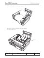
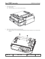
1
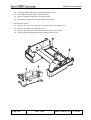
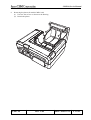
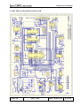
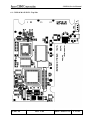
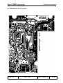
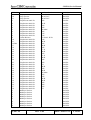
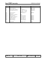
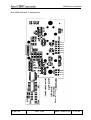
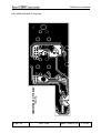
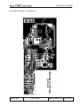
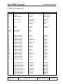
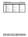
CMP-10 Service Manual
CMP-10
SERVICE MANUAL
PRODUCT NAME:
TERRITORY:
REVISION:
DATE:
CMP-10
TD
1.0
2002.07.25
DESIGNED:
APPROVED:
APPROVALS:
R&D Department
QC Department
Manufacturing Department
Marketing Department
CMP-10
Rev. 1.00
:
:
:
:
Date: 2002.07.25
P 1/41
CMP-10 Service Manual
REVISION
Rev. No.
Date
Rev. 1.0
July 24, 2002
CMP-10
Comment
Newly issued
Rev. 1.00
Date: 2002.07.25
P 2/41
CMP-10 Service Manual
INTRODUCTION
This manual describes the disassembly, reassembly, and maintenance procedures of Citizen Mobile Printer
CMP-10. It is intended for field maintenance men.
1. FEATURES
This small, portable line thermal printer is designed for various types of Personal Data Assistance (PDAs)
devices, notebook computers, mobile phones etc. Its abundant built-in features allow you to widely use this
printer for different applications.
Prior to using it, read and understand this manual thoroughly.
(1)
(2)
(3)
(4)
(5)
(6)
(7)
(8)
(9)
Small, lightweight, you can carry it everywhere
High speed and low noise, owing to line thermal print
Long-life printing head and high reliability, owing to the simple mechanism
Easy paper-loading, owing to clamshell mechanism
Built-in input buffer - 64 K
Capable of printing a bar code (Special command)
Capable of IrDA communication
Capable of using magstripe reader
Interfaces to Pocket PC and PALM OS devices
CMP-10
Rev. 1.00
Date: 2002.07.25
P 3/41
CMP-10 Service Manual
2. GENERAL SPECIFICATIONS
Feature
1. Printing system
2. Printing speed
3. Printing head
4. Emulation
5. Characters
6. Characters per line
7. Dot matrix
8. Bar code type
9.
10.
11.
12.
13.
14.
15.
Paper feed system
Paper width
Paper thickness
Recommended paper
Paper roll maximum diameter
Minimum core diameter
Interfaces
16. IrDA Interface
17. Serial interface
18. Input buffer
19. Mag stripe reader
20. LED color
CMP-10
Parameters
Direct thermal printing
50 mm/sec
Total dots: 384
Dot density: 8 dots/mm
Printing width: 48 mm
ESC/POS commands + Unique commands
(with some unique functions)
ASCII Code, Alphanumeric characters,
International characters, Windows Code page
FONT A: 32 characters/line, FONT B: 42 characters/line
FONT A: 12H × 24V, FONT B: 19H × 16V
UPC-A/E, JAN(EAN)13/8 columns, ITF, CODE39,
CODE128, CODABAR
Friction feed
58 ±0.5 mm
60 - 65 µm
TF50-KS-E2D (Nippon Paper)
40 mm (CMP-10-40), 50 mm (CMP-10-50)
8 mm
IrDA version 1.0
Serial interface (by special cable - option)
Mode: Infrared transceiver mode
Transport wave: Wave length - 850 to 900 nm
Communication speed: 9600, 19200, 38400, 57600,
115200 bps
Data length: 8 bits
Start bit: 1 bit
Stop bit: 1 bit
Parity: none
Communication: Half duplex
Flow control: IrDA standard
Communication distance: Max. 80 cm
Speed: 1200, 2400, 4800, 9600, 19200, 57600, 115200 bps
Interface: Bidirectional serial communication
Signal level: RS-232C
Data lenght: 8 bits
Start bit: 1 bit
Stop bit: 1 bit
Parity: None
Flow control: Xon/Xoff only
Connector: Motorola Star Tac
64 KB
Track 1, 2, 3
Power LED: GREEN and RED
Charge LED: GREEN and RED
Rev. 1.00
Date: 2002.07.25
P 4/41
CMP-10 Service Manual
Feature
21. Operation switches
22. Sensors and error monitoring
23. Power consumption
24. Battery
25. Battery charging time
26. Maximum lines printed with
fully charged battery
27. Power supply monitoring
28. AC Adapter
29. Operating Environment
30. Storage Environment
31. Reliability
32. Safety standard and EMI
33.Dimensions
34. Weight
35. Options
CMP-10
Parameters
Power switch 1, LF switch 1
Paper end sensor, Open cover sensor,
Head temperature, Low battery
Idle - approximately 2W
When printing - approximately 15W
Battery type: Li-ion battery pack
Cell Voltage: 3.7 V
Number of cells: 2
Battery pack voltage: 7.4 V
Battery pack capacity: 2000 mAh
Approximately 3 hours by main unit + AC adapter
40,000 lines
(At temperature 20°C, standard setting, alphanumeric
slide pattern printing. The number of lines may be changed
by such condition as temperature, etc.)
Auto Power OFF (programmable - from 1 to 60 sec.)
Low battery monitoring included.
Model: 10AD-JU (for Japan, USA, and Canada)
10AD-E (Europe)
Input voltage 90 V - 264 V AC
Output voltage 9.0 V DC 1.0 A
Temperature: 5 – 40°C
Humidity: 35 – 80% RH (No dew condensation)
Temperature: –20 – 60°C
Humidity: 10 – 90% RH (No dew condensation)
Print head: 50,000,000 pulses or 50km
(Normal temperature, 12.5% density, rated energy)
Mechanism: 15,000,000 lines
UL, C-UL, TUV, GS, CE Marking
FCC Class B, VCCI Class B
116 (W) × 104 (D) × 63 (H) mm
(50 mm paper cover + Mag stripe reader)
Approx. 370 g (with battery and belt clip without paper)
Serial Cable, Mag Stripe card reader (Factory option)
Rev. 1.00
Date: 2002.07.25
P 5/41
CMP-10 Service Manual
3. DISASSEMBLY AND REASSEMBLY
In case of maintenance work, observe the following:
CAUTION
(1) If the printer functions properly, do not disassemble, reassemble, or adjust it. Particularly, do not loosen
each set screw unless required.
(2) After inspecting the printer, be sure to confirm that it is free from error.
(3) Never try to print without setting the printing paper in the printer. Confirm that it is properly set.
(4) In case of maintenance work, be careful not to leave the used parts or screws in the printer.
(5) When handling the thermal head or control board, do not wear the gloves which will easily cause static
electricity. Prior to handling it, discharge static electricity from your body. Also, never conduct
maintenance work in a place where the printer will be easily electrified.
(6) When disassembling and reassembling, check the cords and boards for any damage, and do not cable or
fix them in an inappropriate manner by force.
(7) Never carry out maintenance work with the power turned on.
3.1 Disassembly Procedure
1.
Prior to Disassembly
(1) Disconnect all the cables from the the main body. For your safety, unplug a power cord from a
plug socket.
(2) Open the paper cover.
CMP-10
Rev. 1.00
Date: 2002.07.25
P 6/41
CMP-10 Service Manual
(3) Remove the paper roll from the paper magazine.
(4) Unscrew the screw on the bottom of the paper magazine.
(5) Close the paper cover.
Screw
CMP-10
Rev. 1.00
Date: 2002.07.25
P 7/41
CMP-10 Service Manual
2.
Removing the battery cover
(1) Press the marked area on the battery cover and lift the cover.
3.
Removing the battery
(1) Open the battery cover as shown above.
(2) Take out the battery pack.
(3) Disconnect the battery pack from the connector.
(4) Remove the battery pack from the battery compartment.
CMP-10
Rev. 1.00
Date: 2002.07.25
P 8/41
CMP-10 Service Manual
(5) Remove two M3 × 10 (BT) screws.
4.
Removing the back cover
(1) Turn the printer downward.
(2) Push the front cover at the places shown on the drawing and lift the back cover.
(3) Remove the back cover.
CMP-10
Rev. 1.00
Date: 2002.07.25
P 9/41
CMP-10 Service Manual
5.
Removing the paper cover
(1) Lift the printer.
(2) Take out the paper cover as shown on the drawing.
6.
Removing the Main PCB and Operational Panel
(1) Unscrew the three screws with which the Main PCB is fixed to the plastic case as shown on the
drawing.
CMP-10
Rev. 1.00
Date: 2002.07.25
P 10/41
CMP-10 Service Manual
(2)
(3)
(4)
(5)
7.
Lift up the Main PCB together with the operational panel.
Disconnect the printer cables and Buzzer cable.
Remove the Main PCB and the operational panel.
Disconnect the Operational panel from the Main PCB.
Removing the printer
(1) Unscrew the four screws which are fixing the printer to the plastic case.
(2) Remove the module from the plastic case.
(3) Unscrew the two screws which fix the printer to the plastic carrier.
(4) Pull the printer forward and detach it from the plastic carrier.
CMP-10
Rev. 1.00
Date: 2002.07.25
P 11/41
CMP-10 Service Manual
8.
Removing the platen (for model CMP-10-40)
(1) Unscrew the screws as shown on the drawing.
(2) Detach the platen.
CMP-10
Rev. 1.00
Date: 2002.07.25
P 12/41
CMP-10 Service Manual
9.
Removing the Operational Panel PCB
(1) Unscrew the two screws and detach the Operational Panel PCB from the plastic panel.
3.2 Reassembly Procedure
Reassemble the disassembled parts in the reverse order of the disassembly procedure described in 3.
CAUTION:
1. Route the cables very carefully so that they will not be caught.
• The flat cable should be located on the board side.
2. Tighten the screws firmly, but avoid tightening them too hard.
3. Use only the attached screws. There are several kinds of screws used. If they are unscrewed, be sure
to put them back in their original places.
4. After reassembly, be sure to check prior to turning on the power.
CMP-10
Rev. 1.00
Date: 2002.07.25
P 13/41
CMP-10 Service Manual
4. TROUBLESHOOTING
4.1 Troubleshooting Procedure
If the printer has a trouble, confirm its phenomenon, determine a defective part according to 4.2 Troubleshooting
Guide, and then, repair it in the specified manner.
• Phenomenon
Find a corresponding trouble phenomenon in this column. If there multiple corresponding phenomena,
confirm taking all of them into account.
This allows you to determine a hidden defective part.
• Cause
Possible causes are listed as many as possible in this column. Project a trouble cause and determine it by
the check method described in the next column.
• Check Method
Check methods are listed in this column to determine the relevant trouble cause.
• Repair Method
Repair the defective part in the manner described in this column.
Efficient troubleshooting is enabled without making a erroneous judgment by repairing in the above-mentioned
procedure.
4.2 Troubleshooting Guide
The following table lists the check methods and repair methods based on possible phenomena and causes.
AC Adapter Failure
Phenomenon
Charging LED is not
shining though DC
adapter is connected.
Cause
The AC cord is not
connected to Power inlet.
Check Method
—
The voltage is abnormal.
Use a voltmeter to
(It is slightly higher than the measure a supply
rating in the no-load state) voltage.
The AC adapter was
—
connected to another
device in the past.
CMP-10
Rev. 1.00
Repair Method
Connect the AC cord to
the specified plug
socket, etc.
Replace the AC
adapter.
Replace the AC
adapter.
Date: 2002.07.25
P 14/41
CMP-10 Service Manual
Power Supply Failure
Phenomenon
The power cannot be
turned on.
(POWER lamp not
illuminated)
Cause
Check Method
The AC adapter is not
—
connected.
Check if the battery
Battery pack is not
connected.
pack is connected.
Battery pack is discharged. Connect the AC adapter
and check that the
charge LED is blinking.
The fuse is gone.
Check whether or not
the non-specified power
supply was used in the
past.
Check whether or not
the specified fuse is
used.
Others
Check whether or not
the specified power
supply is used.
Check whether or not
the operation panel
board is connected.
The fuse blows out
The printer mechanism or The power is turned on
immediately if replaced. control board is defective. by disconnecting the
It blows out during
cable of the printer
operation.
mechanism.
(Does not operate)
(F2 blows out)
The phenomenon
remains unchanged
after the abovementioned check.
The motor or driver of the The power is turned on
printer mechanism is
by disconnecting the
defective.
motor cable.
(Does not operate)
The phenomenon
remains unchanged
after the abovementioned check.
CMP-10
Rev. 1.00
Repair Method
Connect the specified
AC adapter.
Connect proper battery
pack.
Charge the battery
pack.
Use the specified AC
adapter.
Use the specified fuse.
Use the specified AC
adapter.
Replace the cable of the
operation panel board.
Connect the connector.
Replace the printer
mechanism.
Replace the control
board.
Replace the printer
mechanism.
Replace the motor
driver or control board.
Date: 2002.07.25
P 15/41
CMP-10 Service Manual
Phenomenon
No printing
Thin printing color
Missing dots
Missing dots in specific
section
CMP-10
Cause
Faulty battery pack
Check Method
Check whether or not
the specified Battery
pack is used.
Battery pack is discharged. Connect the AC adapter
and check that the
charge LED is shining.
Faulty mounting and
Check mounting and
connection of printer
connection of the printer
mechanism
mechanism.
The printer operates
Check whether or not
properly except not printing the specified paper is
used, and whether or
not the specified paper
is set inside.
Faulty printer mechanism
—
The head is heated due to
continuous print, etc.
Faulty battery pack
Wait for some time.
Check whether or not
the specified battery
pack is used.
Battery pack is discharged Connect the AC adapter
and check that the
charge LED is blinking.
Non-recommended paper Set print density higher
with the proper
command.
Faulty thermal head
—
Faulty printer mechanism
connection
Repair Method
Use the specified
Battery pack.
Charge the battery
pack.
Mount the printer
mechanism properly.
Set the specified paper
properly.
Replace the printer
mechanism.
Reset automatically.
Use specified battery
pack.
Charge the battery
pack.
Replace with the
recommended paper or
its equivalent.
Replace the thermal
head.
Connect the printer
mechanism cable
properly.
Check whether or not
the printer mechanism
cable is connected
properly.
Foreign substance adhered Check the thermal head Dip a cotton swab or
to the thermal head or
and platen roller for any soft cloth in ethyl
platen roller
alcohol and wipe off the
foreign substance.
foreign substance.
Faulty thermal head
—
Replace the thermal
head.
Faulty connection of printer Check whether or not
Connect the printer
mechanism
the printer mechanism
mechanism cable
cable is connected
properly.
properly.
Faulty thermal head
Replace the thermal
—
head.
Rev. 1.00
Date: 2002.07.25
P 16/41
CMP-10 Service Manual
Phenomenon
Low print quality
Too much ink blot
Blurred characters
Cause
Faulty printing paper
Check Method
Check whether or not
the specified printing
paper is used.
Faulty battery pack
Check whether or not
the specified battery
pack is used.
Foreign substance adhered Check the thermal head
to the thermal head or
and platen roller for any
platen roller
adhered foreign
substance.
Faulty printing paper
Check whether or not
the specified printing
paper is used.
Worn platen roller
The platen roller is worn
out and slips easily.
Repair Method
Replace with the
recommended paper or
its equivalent.
Use the specified
battery pack.
Dip a cotton swab or
soft cloth in ethyl
alcohol and wipe off the
foreign substance.
Replace with the
recommended paper or
its equivalent.
Replace the platen roller
unit.
* If the printer continues to print for a long time, the printed characters become thicker. If printing is
suspended and restarted, print concentration will change slightly. Print density becomes lower if used at
a low temperature.
* Paper Feed Failure
Phenomenon
Cause
Faulty
connection
of motor
A printing paper feed
motor does not work or connector
malfunctions.
Faulty battery pack
Faulty motor body
The printing paper is not Faulty paper feed
fed or fed unproperly.
Foreign substance in the
gear
Broken gear
Faulty motor body
CMP-10
Rev. 1.00
Check Method
Check the motor
connector for its
connection.
Check whether or not
the specified battery
pack is used.
Use a tester or
oscilloscope to measure
a supply voltage and
waveform.
Check whether or not
the printing paper is
jamming or torn and
caught in a paper path.
Check the motor gear
for any foreign
substance.
Check whether or not
the motor gear is
broken.
Use a tester or
oscilloscope to measure
a supply voltage and
waveform.
Repair Method
Connect the connector
properly.
Use the specified
battery pack.
If the supply voltage
and waveform are
normal, replace the
motor (printer
mechanism).
Remove unnecessary
printing paper and set
properly.
Remove the foreign
substance.
Replace the motor
(printer mechanism).
If the supply voltage
and waveform are
normal, replace the
motor (printer
mechanism).
Date: 2002.07.25
P 17/41
CMP-10 Service Manual
* PE Sensor Failure
Phenomenon
Cause
PE is always detected. Faulty sensor
PE is not detected.
Faulty sensor
Foreign substance caught
by the sensor
Sensor exposed to the
direct sunshine or strong
light
Check Method
Use a tester to check
whether or not a supply
voltage and signal are
normal.
—
Check for any foreign
substance.
Check operation,
avoiding the direct
sunshine or strong light.
Repair Method
Replace the PE sensor.
Replace the PE sensor.
Remove the foreign
substance.
Use in a place free
from the direct sunshine
or strong light.
* If PE is not detected with no printing paper set, the printer will print even if the paper is not set, causing a
trouble to the printer head, etc. If printing is performed in this condition, replace the platen roller and head.
* Others (Operational Failure Included)
Phenomenon
At power-on, the
CHARGE and ON
lamps remain
illuminated.
At power-on, the
ERROR lamp blinks.
Kanji is not printed.
Cause
Faulty control board
Faulty memory
No Kanji ROM
Faulty Kanji ROM
Erroneous printing or
malfunctioning.
The printer is used in a
noisy place
A printer body or
internal temperature is
high.
Bad working environment
CMP-10
Rev. 1.00
Check Method
—
—
Check whether or not
the printer is for
overseas use.
—
Check whether or not
there is any noise
emitting object around
the printer.
Check the working
environment and
installation site.
Repair Method
Replace the control
board.
Replace the memory or
control board.
Replace the control
board with one for
domestic use or attach
the Kanji ROM.
Replace the Kanji
ROM.
Change the place.
Move the printer to a
well-ventilated place
within the specified
temperature range.
Date: 2002.07.25
P 18/41
CMP-10 Service Manual
5. ASSEMBLY DRAWING
CMP-10
Rev. 1.00
Date: 2002.07.25
P 19/41
CMP-10 Service Manual
POS
1
2
3
4
5
6
7
8
9
10
11
12
13
14
15
16
17
18
19
CMP-10
Name
Cover Front
Button
Printer base
Paper cover 40 mm
Cover back
Lamella
Rubber foot
Belt clip
Screw M3 × 6
Strap hook
RS connector cover
Main PCB
Screw M2.5 × 8
OP Panel PCb
Battery cover
OP Panel
LiION Battery
Screw M2.5 × 6
Screw M2 × 6.5
Rev. 1.00
Quantity
1
1
1
1
1
1
2
1
2
2
1
1
4
1
1
1
1
10
2
Date: 2002.07.25
P 20/41
CMP-10 Service Manual
6. ELECTRICAL DIAGRAM OF MAIN PCB
CMP-10
Rev. 1.00
Date: 2002.07.25
P 21/41
CMP-10 Service Manual
6.1 CMP-10 MAIN PCB - Top Side
CMP-10
Rev. 1.00
Date: 2002.07.25
P 22/41
CMP-10 Service Manual
6.2 CMP-10 MAIN PCB - Bottom Side
CMP-10
Rev. 1.00
Date: 2002.07.25
P 23/41
CMP-10 Service Manual
6.3 CMP-10 MAIN PCB - Top Side
CMP-10
Rev. 1.00
Date: 2002.07.25
P 24/41
CMP-10 Service Manual
6.4 CMP-10 MAIN PCB - Bottom Side
CMP-10
Rev. 1.00
Date: 2002.07.25
P 25/41
CMP-10 Service Manual
7. MAIN PCB - PARTS LIST
No.
U1
U2
U3
U4
U5
Name
Interface IC
Battery charging IC
A/D Converter
CMOS IC
CMOS IC
Part Number
SP232ECT
MM1433BV
TLC0832
CD4066
CD4066
Manufacturer
SIPEX
MITSUMI
TI
FAIRCHILD
FAIRCHILD
U6
1 Mbit SRAM
K6T1008C2E-GB70 /5V
SAMSUNG
U7
U8
U9
U10
U11
U12
U13
IrDA Controller
CPU
Flash ROM
Flash ROM
8 BIT LATCH
Voltage Regulator
CMOS IC
Reset IC
U14
Motor controller IC
TOIM4232
W78E516B PLCC
W29EE011P-90 PLCC
M29C400
74HCT573CDR
LM2931ADT50
CD4066
SP690ACN (SMD)
MAX690ACS
SP703ACN
LB1838M
VISHAY
WINBOND
WINBOND
ST
TI TI, PHLPS,
ON SEMI, NS
FAIRCHILD
SIPEX
MAXIM
SIPEX
SANYO
Q1
Q2
FET Transistor
PNP Transistor
Q3
X’TAL
IRFR9014 D-Pak
KTA1504
2SA1162-GR
40 MHz/HC49S
IR
KEC
TOSHIBA
SUNNY
Q4
NPN Transistor
Q5
Transistor
Q6
Q7
X’TAL
PNP Transistor
KTC3875
2SC2712-GR
KTA1715
2SA715
3.6864 MHz/HC49S
KTA1504
2SA1162-GR
KEC
TOSHIBA
KEC
HITACHI
SUNNY
KEC
TOSHIBA
Q8
NPN Transistor
Q9
PNP Transistor
Q10
NPN Transistor
KTC3875
2SC2712-GR
KTA1504
2SA1162-GR
KTC3875
2SC2712-GR
KEC
TOSHIBA
KEC
TOSHIBA
KEC
TOSHIBA
CMP-10
Rev. 1.00
Date: 2002.07.25
P 26/41
CMP-10 Service Manual
No.
D1
D2
D3
D4
D5
D6
D7
D8
D9
D10
D11
D12
D13
D14
D15
D16
D17
C1
C2
C3
C4
C5
C6
C7
C8
C9
C10
C11
C12
C13
C14
C15
C16
C17
C18
C19
C20
C21
C22
C23
C24
C25
C26
C27
C28
Name
Fast Recovery Diode
Fast Recovery Diode
Fast Recovery Diode
Diode
Fast Recovery Diode
Diode
Diode
Diode
Diode
Diode
Diode
Diode
Diode
Diode
Diode
Diode
Diode
Chip capacitor
Ceramic capacitor
Chip capacitor
Chip capacitor
Chip capacitor
Chip capacitor
Chip capacitor
Chip capacitor
Chip capacitor
Chip capacitor
Chip capacitor
Chip capacitor
Chip capacitor
Chip capacitor
Chip capacitor
Electrolytic capacitor
Electrolytic capacitor
Chip capacitor
Chip capacitor
Electrolytic capacitor
Chip capacitor
Chip capacitor
Chip capacitor
Chip capacitor
Chip capacitor
Chip capacitor
Chip capacitor
Chip capacitor
CMP-10
Part Number
SR240
SR240
SR240
LL4148
SR240
LL4148
LL4148
LL4148
LL4148
LL4148
LL4148
LL4148
LL4148
LL4148
LL4148
LL4148
LL4148
1 µF/16 V
100 nF/50 v
1 µF/16 V
1 µF/16 V
GRM
1 µF/16 V
10 nF/50 V
100 nF/50 v
100 nF/50 v
15 pF/50 V
15 pF/50 V
100 nF/50 v
5 pF/50 V
5 pF/50 V
100 nF/50 v
100 µF/10 V
100 µF/10 V
100 nF/50 v
100 nF/50 v
1000 µF/10 V
100 nF/50 V
100 nF/50 V
100 nF/50 V
100 nF/50 V
100 nF/50 V
100 nF/50 V
100 nF/50 V
100 nF/50 V
Rev. 1.00
Manufacturer
DAESAN
DAESAN
DAESAN
DAESAN
DAESAN
DAESAN
DAESAN
DAESAN
DAESAN
DAESAN
DAESAN
DAESAN
DAESAN
DAESAN
DAESAN
DAESAN
DAESAN
WALSIN
WALSIN
WALSIN
WALSIN
MURATA
WALSIN
WALSIN
WALSIN
WALSIN
WALSIN
WALSIN
WALSIN
WALSIN
WALSIN
WALSIN
SAMWHA
SAMWHA
WALSIN
WALSIN
WALSIN
WALSIN
WALSIN
WALSIN
WALSIN
WALSIN
WALSIN
WALSIN
WALSIN
Date: 2002.07.25
P 27/41
CMP-10 Service Manual
No.
C29
C30
C31
R1
R2
R3
R4
R5
R6
R7
R8
R9
R10
R11
R12-R16
R17
R18
R19
R20
R21
R22
R23
R24
R25
R26
R27
R28
R29
R30
R31
R32
R33
R34
R35
R36
R37
R38
V1
V2
V3
V4
V5
V6
V7
V8
Name
Chip capacitor
Chip capacitor
Chip capacitor
Chip Resistor 0805 5%
Chip Resistor 0805/5%
Chip Resistor 0805/5%
Chip Resistor 0805/5%
Chip Resistor 0805/5%
Chip Resistor 0805/5%
Chip Resistor 0805/5%
Chip Resistor 0805/5%
Carbon Resistor
Chip Resistor 0805/5%
Chip Resistor 0805/5%
Chip Resistor 0805/5%
Chip Resistor 0805/5%
Chip Resistor 0805/5%
Chip Resistor 0805/5%
Chip Resistor 0805/5%
Chip Resistor 0805/5%
Chip Resistor 0805/5%
Chip Resistor 0805/5%
Chip Resistor 0805/5%
Chip Resistor 0805/5%
Chip Resistor 0805/5%
Chip Resistor 0805/5%
Chip Resistor 0805/5%
Chip Resistor 0805/5%
Chip Resistor 0805/5%
Chip Resistor 0805/5%
Chip Resistor 0805/5%
Chip Resistor 0805/5%
Chip Resistor 0805/5%
Chip Resistor 0805/5%
Chip Resistor 0805/5%
Chip Resistor 0805/5%
Chip Resistor 0805/5%
Multilayer Varistor
Multilayer Varistor
Multilayer Varistor
Multilayer Varistor
Multilayer Varistor
Multilayer Varistor
Multilayer Varistor
Multilayer Varistor
CMP-10
Part Number
100 nF/50 V
100 nF/50 V
100 nF/50 V
10 K
130 K
10 K
10 K
150 Ohm
10 K
33 K
33 K
0.3 Ohm/1 W/5%
33 K
100 K
10 K
100 K
10 K
4.7 K
100 K
10 K
2.2 K
100 K
10 K
10 K
1K
100 K
10 K
100 K
220 Ohm
10 K
10 K
100 K
100 K
10 K
10 K
10 K
1K
Rev. 1.00
Manufacturer
WALSIN
WALSIN
WALSIN
YAGEO
YAGEO
YAGEO
YAGEO
YAGEO
YAGEO
YAGEO
YAGEO
YAGEO
YAGEO
YAGEO
YAGEO
YAGEO
YAGEO
YAGEO
YAGEO
YAGEO
YAGEO
YAGEO
YAGEO
YAGEO
YAGEO
YAGEO
YAGEO
YAGEO
YAGEO
YAGEO
YAGEO
YAGEO
YAGEO
YAGEO
YAGEO
YAGEO
YAGEO
WALSIN
WALSIN
WALSIN
WALSIN
WALSIN
WALSIN
WALSIN
WALSIN
Date: 2002.07.25
P 28/41
CMP-10 Service Manual
No.
V9
F1
F2
L1
Name
Multilayer Varistor
Fuse F-1206(1A)
Fuse F-1206(3.5A/20V~)
Ferite bead 2012 0,1uH
CN1
CN2
CN3
CN4
CN5
CN7
CN8
CN9
3 Pin Connector
Power jack
STAR TAC Connector
2 Pin Connector
24 Pin FPC Connector
12 PIN connector
6 Pin Connector
9 Pin Connector
PCB
PCB MAIN
CMP-10
Part Number
(1 A)
(2.5 A/20 V~)
25 MHZ/~50 OHM,
100 MHz/~75 Ohm
Molex 5267-03
Manufacturer
WALSIN
BEL FUSE
BEL FUSE
SAMWHA
MOLEX
6008
Molex 53398-02
Molex 52610-24
Molex 79107-12
Molex 79107-06
Molex 53398-09
MOLEX
MOLEX
MOLEX
MOLEX
MOLEX
CMP-10 V2.0
JND
Rev. 1.00
Date: 2002.07.25
P 29/41
CMP-10 Service Manual
8. PANEL PCB - Top View
CMP-10
Rev. 1.00
Date: 2002.07.25
P 30/41
CMP-10 Service Manual
8.1 PANEL PCB ASS’Y - Bottom View
CMP-10
Rev. 1.00
Date: 2002.07.25
P 31/41
CMP-10 Service Manual
8.2 PANEL PCB ASS’Y - Top View
CMP-10
Rev. 1.00
Date: 2002.07.25
P 32/41
CMP-10 Service Manual
8.3 PANEL PCB ASS’Y - Bottom View
CMP-10
Rev. 1.00
Date: 2002.07.25
P 33/41
CMP-10 Service Manual
9. PANEL PCB - PARTS LIST
No.
U1
U2
U3
Name
INFRARED TRANCEIVER
F2F2000
Analog switch IC
Part Number
TFDU4100
F2F2000
CD4066
Manufacturer
VISHAY
ZEPETRONIC
FAIRCHILD
Q1
NPN Transistor
Q2
NPN Transistor
2SA1162-GR
KTA1504
2SA1162-GR
KTA1504
TOSHIBA
KEC
TOSHIBA
KEC
D1
D2
Diode
Diode
LL4148
LL4148
DAESAN
DAESAN
LED1
LED2
Bicolor LED
Bicolor LED
TBD
TBD
R1
R2
R3
R4
R5
R6
R7
R8
R9
R10
R11
R12
R13
R14
R15
R16
R17
R18
Chip Resistor 0805
Chip Resistor 0805
Chip Resistor 0805
Chip Resistor 0805
Chip Resistor 0805
Chip Resistor 0805
Chip Resistor 0805
Chip Resistor 0805
Chip Resistor 0805
Chip Resistor 0805
Chip Resistor 0805
Chip Resistor 0805
Chip Resistor 0805
Chip Resistor 0805
Chip Resistor 0805
Chip Resistor 0805
Chip Resistor 0805
Chip Resistor 0805
10 k/5%
10 k/5%
10 k/5%
100 Ohm/5%
1 k/5%
100 Ohm/5%
1 k/5%
2 k/5%
2,2 M/5%
4.7 k/5%
24 k/5%
2.2 M/5%
1 k/5%
220 Ohm/5%
10 k/5%
2.7 k/5%
10 k/5%
10 k/5%
YAGEO
YAGEO
YAGEO
YAGEO
YAGEO
YAGEO
YAGEO
YAGEO
YAGEO
YAGEO
YAGEO
YAGEO
YAGEO
YAGEO
YAGEO
YAGEO
YAGEO
YAGEO
C1
C2
C3
C4
C5
C6
C7
C8
C9
Chip Capacitor 0805
Chip Capacitor 0805
Chip Capacitor 0805
Chip Capacitor 0805
Chip Capacitor 0805
Chip Capacitor 0805
Chip Capacitor 0805
Chip Capacitor 0805
Chip Capacitor 0805
100 nF/20%
1 µF/20%
10 nF/20%
1 nF/20%
100 nF/20%
100 nF/20%
100 nF/20%
1 nF/20%
22 nF/20%
WALSIN
WALSIN
WALSIN
WALSIN
WALSIN
WALSIN
WALSIN
WALSIN
WALSIN
CMP-10
Rev. 1.00
Date: 2002.07.25
P 34/41
CMP-10 Service Manual
No.
C10
C11
Name
Chip Capacitor 0805
Chip Capacitor 0805
Part Number
10 nF/20%
10 nF/20%
Manufacturer
WALSIN
WALSIN
CN1
N2
CN3
CN4
Magnetic head
12 pin Molex
6 pin Molex
MAGNETIC HEAD
Molex 87049-1016
Molex 87049-0616
MOLEX
MOLEX
SW1
SW2
TACT SWITCH
TACT SWITCH
SKHCAD301A
SKHCAD301A
ALPS ELECTRIC
ALPS ELECTRIC
PCB
PANEL PCB
CMP-10 V2.0
JND
CMP-10
Rev. 1.00
Date: 2002.07.25
P 35/41
CMP-10 Service Manual
BATTERY SPECIFICATION
1. Scope
This Product Specification (‘Specification’ hereinafter) covers the requirements for the rechargeable lithiumion battery Pack manufactured and supplied by Samsung SDI Co., Ltd. to Japan CBM Corporation for its
product “2S¡¿1P Soft Pack”. The battery pack contains lithiumion battery, safety device, a protection
circuit module.
2.
Description and Model
2.1 Description
2.2 Battery
2.3 Battery Pack Model
Rechargeable Lithium-ion battery pack
ICR18650-20
P21R04-03-S01
3.
Ratings
3.1
3.2
3.3
3.4
Nominal Capacity 2000 mAh (0.2 C Discharge)
Nominal Voltage
7.4 V
End Voltage
5.5 V
Charging Method
CC-CV
(Constant-Voltage with Limited current)
3.5 Charging Voltage
3.6 Charging Current
Standard charge
Rapid charge
3.7 Max. Charge current
3.8 Max. Discharge current
3.9 Internal Resistance
3.10 Weight
3.11 Operating Temperature
Standard charge
Standard discharge
3.12 Storage Temperature
–20 ~ 20ºC
–20 ~ 45ºC
–20 ~ 60ºC
3.13 Storage Humidity
CMP-10
8.4 V
1000 mA/3 Hr
2000 mA/2.5 Hr
2000 mA
2000 mA
< 280 m Ohm
About 90.0 g
0 to 45oC
–20 to 60oC
< 1 Year
< 3 Months
< 1 Month
20 ~ 85 % RH (not condensed)
Rev. 1.00
Date: 2002.07.25
P 36/41
CMP-10 Service Manual
4. Outline Dimension
Refer to attached drawing.
5. Appearance
Any critical cosmetic damage must not be found from the appearance of the products.
6.
Standard Test Condition
6.1 Test Sample Condition
The battery pack used for the test shall be new and delivered no more than one month before.
6.2 Environmental Condition
Unless otherwise specified, all tests stated in this specification are conducted at temperature 25 ±5ºC
and humidity 65 ±20% and charged state.
6.3 Test Equipment Condition
The grade of voltmeter and ammeter used in the test shall be higher than class 0.5, a high impedance
type.
7.
Characteristics
7.1 Standard Charge
“Standard charge” means charging the battery pack with a charge current.
1000 mA with constant voltage of 8.4 V with 3.0Hr cutoff
7.2 Initial Capacity
“Initial capacity” is defined as the initial discharge capacity of the battery pack, which is measured with
discharge current of 400 mA with 5.5 V cutoff within 1 hour after the standard charge.
The Initial Discharge Capacity shall be more than 95%.
7.3 Cycle Life
Cycle life is defined by the discharge capacity after 300 Cycles.
Each cycle has a period of
charge with initial current 2000 mA to 8.4 V
rest Capacity 10 minutes
discharge with 2000 mA with 5.5 V cutoff
rest Capacity 30 minutes
Discharge Capacity after 300 cycles > 80% (Initial Capacity).
CMP-10
Rev. 1.00
Date: 2002.07.25
P 37/41
CMP-10 Service Manual
7.4 Initial Internal Impedance
This means AC impedance of the battery pack measured at 1 kHz after standard charge.
Initial internal impedance < 280 m Ohm
7.5 Discharge Capacity with Temperature
This means relative value of discharge capacity at various temperature compared with the discharge
capacity at 25 ±5ºC (100%)
Conditions are:
Standard charge
Discharge current 400mA with 5.5V cutoff
Relative Discharge Capacity
at
80%
0ºC
100%
25ºC
95%
40ºC
7.6 Storage Characteristics
Remaining capacity of the battery pack which was stored at 25 ±5ºC for 30 days is measured by
discharge capacity.
Conditions are :
Standard charge before storage
Discharge current 400 mA with 5.5 V cutoff
Remaining Capacity (after the storage) >80%.
8.
Function of Protection Circuit Module (hereinafter PCM)
8.1 Overcharge Protection
4.35 ±0.025 V/cell
8.2 Overdischarge Protection
2.30 ±0.080 V/cell
8.3 Overcurrent Protection
2 ~ 6.5 A (Ave. 4.25 A) depending upon pack voltage, with reset when load is removed or pack is
recharged.
8.4 Power Dissipation
Run:
Shut down:
CMP-10
15 µA
0.1 µA
Rev. 1.00
Date: 2002.07.25
P 38/41
CMP-10 Service Manual
9.
Safety Test
9.1 Overcharge Test
Test method:
Apply charge voltage 12 V with current 1.0 C to the battery pack.
Criteria:
PCM shall operate and stop charging. Capacity > 87%
No damage such as leakage, flame, fire was allowed.
9.2 External Short Circuit Test
Test method:
Short-circuit the battery pack with 8.4 V charged, by connecting positive and negative terminals
of the battery pack with a resistor less than 100 m Ohm 20 times every second.
Criteria:
PCM shall operate and stop discharging. OCV > 7.2V
No damage such as leakage, flame, fire was allowed.
9.3 Overdischarge Test
Test method:
Discharge the battery pack with current 1.0 C for 12 hours.
Criteria:
PCM shall operate and stop discharging. Capacity > 87%
No damage such as leakage, flame, fire was allowed.
10. Mechanical Characteristics
10.1 Vibration Test
Test method:
This means the endurance of the battery pack against vibration.
Frequency and amplitude:
10 Hz → 55 Hz → 10 Hz / 0.8 mm
Sweep speed :
1 ±0.055 Hz/min
Criteria:
No leakage , OCV > 7.2V, Internal impedance < 320 m Ohm
CMP-10
Rev. 1.00
Date: 2002.07.25
P 39/41
CMP-10 Service Manual
11. Shipment
The battery pack shall be shipped in a 40~60% charged state.
12. Caution and Prohibition
Before using and handling the battery pack, see carefully attached
“Handling Instruction for Lithium Ion Rechargeable Battery Pack”.
13. Others
13.1 Storage for a Long Term
If the battery pack is kept for a long term (3 months or more), it is strongly recommended that the
battery pack be preserved at dry and low temperature atmosphere.
CMP-10
Rev. 1.00
Date: 2002.07.25
P 40/41
CMP-10 Service Manual
Handling Instruction for Lithium Ion Rechargeable Battery Pack
SAFETY INSTRUCTIONS
Please follow the warnings and precautions listed below to avoid possible hazards from the improper use of
batteries and to ensure correct and safe use of them. The following notes should be put in an appropriate and
effective location in each end-use product and its instruction manual.
Warning
1. Do not short-circuit the battery, as it may generate heat.
To avoid short-circuiting, do not let the battery come in contact with metal objects at any time, especially
when transporting.
2. Do not put the battery into a fire, as it may swell or explode. Do not use near any type of heat source.
When battery leaks electrolyte or emit a strange smell, discontinue use and move battery away from
the heat source.
3. Cover terminals with insulating tape before proper disposal.
4. Do not solder the battery directly. Heat applied during soldering may damage the safety vent in the
battery’s positive cover.
5. Do not alter or disassemble the battery. Do not take off the battery’s cover or jacket.
6. Do not deform the battery by applying pressure. Do not throw, hit or drop the battery. Do not subject
the battery to mechanical shocks.
7. Do not submerge the battery in water, or any type of liquid.
Do not expose the battery to any type of water, such as rain or moisture, as it might heat, corrode, or
not function occasionally.
8. Do not connect the battery reversed in positive (+) and negative (−) terminals. Do not charge the
battery with polarities reversed, as it may swell or explode.
9. Do not use any chargers not specified by manufacturer .
Do not charge the battery under conditions not specified, as it may leak electrolyte, heat or explode.
10. Do not use the battery with other makers’ batteries, different types and or models of batteries such as
dry batteries, nickel-metal hydride batteries, or nickel-cadmium batteries. Do not use old and new Liion batteries together, as they might leak electrolyte, heat or explode.
11. Do not mistreat the battery, or use the battery in applications not recommended by manufacturer.
12. Do not let electrolyte come into contact with skin, eyes, or clothing. If contact with skin or eyes occurs,
immediately seek help from a doctor.
13. Keep the battery out of reach of babies and children to avoid any accidents.
14. Do not put batteries in a microwave oven or pressure cooker.
15. Although rechargeable, the battery has a limited life-span. Replace when usage time between charges
become short.
16. Do not store at or use in temperatures above 60ºC.
17. Do not short-circuit the cells when open the carton.
18. If there are any problems of the battery, immediately keep the battery at safe place and contact to Japan
CBM Corporation.
CMP-10
Rev. 1.00
Date: 2002.07.25
P 41/41