1
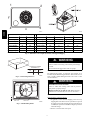
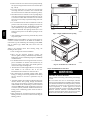
3. Attach each of the 4 metal rigging brackets under the panel
rain lip (See Fig. 5). Use the screws removed in step 2 above
to secure the brackets to the unit.
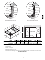
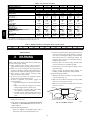
1” (25mm) MIN.
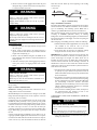
WARNING
TRAP
OUTLET
2” (50mm) MIN.
PROPERTY DAMAGE HAZARD
Failure to follow this warning could result in personal
injury/death or property damage.
C99013
Fig. 8 -- Condensate Trap
Rigging bracket MUST be under the rain lip to provide
adequate lifting.
!
Step 7—Install Duct Connections
The design and installation of the duct system must be in accordance
with the standards of the NFPA for installation of non--residence
type air conditioning and ventilating systems, NFPA 90A or
residence type, NFPA 90B and/or local codes and ordinances.
WARNING
PROPERTY DAMAGE HAZARD
Select and size ductwork, supply--air registers, and return air grilles
according to ASHRAE (American Society of Heating,
Refrigeration, and Air Conditioning Engineers) recommendations.
The unit has duct flanges on the supply-- and return--air openings on
the side of the unit.
Failure to follow this warning could result in personal
injury/death or property damage.
Do not strip screws when re--securing the unit. If a screw is
stripped, replace the stripped one with a larger diameter screw
(included).
When designing and installing ductwork, consider the following:
Rigging/Lifting of Unit
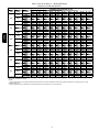
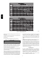
1. All units should have field--supplied filters or accessory filter
rack installed in the return--air side of the unit.
Recommended sizes for filters are shown in Table 1.
1. Bend top of brackets down approximately 30 degrees from
the corner posts.
2. Avoid abrupt duct size increases and reductions. Abrupt
change in duct size adversely affects air performance.
2. Attach straps of equal length to the rigging brackets at
opposite ends of the unit. Be sure straps are rated to hold the
weight of the unit (See Fig. 5).
IMPORTANT: Use flexible connectors between ductwork and
unit to prevent transmission of vibration. Use suitable gaskets to
ensure weather--tight and airtight seal. When electric heat is
installed, use fireproof canvas (or similar heat resistant material)
connector between ductwork and unit discharge connection. If
flexible duct is used, insert a sheet metal sleeve inside duct. Heat
resistant duct connector (or sheet metal sleeve) must extend 24--in.
from electric heater element.
3. Attach a clevis of sufficient strength in the middle of the
straps. Adjust the clevis location to ensure unit is lifted level
with the ground.
4. After unit is securely in place detach rigging straps. Remove
corner posts, screws, and rigging brackets then reinstall
screws.
!
WARNING
3. Size ductwork for cooling air quantity (cfm). The minimum
air quantity for proper electric heater operation is listed in
Table 2. Heater limit switches may trip at air quantities below
those recommended.
UNIT FALLING HAZARD
Failure to follow this warning could result in personal
injury/death or property damage.
4. Seal, insulate, and weatherproof all external ductwork. Seal,
insulate and cover with a vapor barrier all ductwork passing
through conditioned spaces. Follow latest Sheet Metal and
Air Conditioning Contractors National Association
(SMACNA) and Air Conditioning Contractors Association
(ACCA) minimum installation standards for residential
heating and air conditioning systems.
When straps are taut, the clevis should be a minimum of 36
inches above the unit top cover.
After the unit is placed on the roof curb or mounting pad, remove
the top crating.
Step 6—Connect Condensate Drain
NOTE: When installing condensate drain connection be sure to
comply with local codes and restrictions.
5. Secure all ducts to building structure. Flash, weatherproof,
and vibration--isolate duct openings in wall or roof
according to good construction practices.
Model 50SD disposes of condensate water through a 3/4 in. NPT
fitting which exits through the base on the evaporator coil access
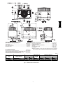
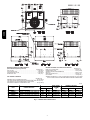
side. See Fig. 2 & 3 for location.
CONFIGURING UNITS FOR DOWNFLOW (VERTICAL)
DISCHARGE
Condensate water can be drained directly onto the roof in rooftop
installations (where permitted) or onto a gravel apron in ground
level installations. Install a field--supplied condensate trap at end of
condensate connection to ensure proper drainage. Make sure that
the outlet of the trap is at least 1 in. lower than the drain pan
condensate connection to prevent the pan from overflowing (See
Fig. 8). When using a gravel apron, make sure it slopes away from
the unit.
!
WARNING
ELECTRICAL SHOCK HAZARD
Failure to follow this warning could result in personal injury
or death.
Before performing service or maintenance operations on the
system, turn off main power to unit and install lockout tag.
Connect a drain tube using a minimum of 3/4 --in. PVC or 3/4 --in.
copper pipe (all field--supplied) at the outlet end of the 2--in. trap. Do
not undersize the tube. Pitch the drain tube downward at a slope of
at least 1--in. for every 10 ft of horizontal run. Be sure to check the
1. Open all electrical disconnects and install lockout tag before
starting any service work.
7
50SD
!
drain tube for leaks. Prime trap at the beginning of the cooling
season start--up.