1
CA22, 23, 31, 41 & 51
All models include
RCA inputs
High Level input
Continuos variable low pass and/or high
pass crossover
Bass boost feature (only on CA23 & CA41)
Remote turn on / off
Automatic remote turn on/ off on high level
input without connecting any remote wire
Electronic protection circuitry against
short-circuit, DC offset and thermal overload.
Bridgeable design to direct full power to
one or two subwoofers etc.
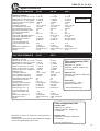
CA22
2 x 60 Watt RMS / 2 x 100 Watt max in 2 ohm
1x 200 Watt RMS bridged
CA23
2 x 135 Watt RMS / 2 x 200 Watt max in 2 ohm
1 x 400 Watt RMS bridged
CA31
2 x 65 Watt RMS / 2 x 90 Watt max in 2 ohm
1 x 170 Watt RMS bridged
1 x 170 W RMS on sub channel
CA41
4 x 70 Watt RMS / 4 x 125 Watt max in 2 ohm
2 x 200 Watt RMS bridged
CA51
4 x 50 Watt RMS / 4 x 80 Watt max in 2 ohm
2 x 150 Watt RMS bridged
1 x 170 Watt RMS on sub channel
All above RMS power ratings with 4 ohm load
at 13,8 Volt DC.
Installation
Before you begin installation
Before you begin you need to read the manual, to have
some tools, cables and other material available. There
is one such list of material on the following page.
Amplifier location
Important
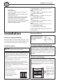
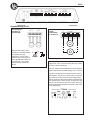
Allow air circulation around the amplifier.
The DLS Performance series of amplifiers have a
compact design that allows great flexibility in
mounting. You can mount it under a seat or in the
trunk.
When you select a location, do remember that the
amplifier generates a lot of heat.
Choose a location where air can circulate freely
around the amplifier. Do not cover the amplifier
with carpets or hide behind trim panels.
Do not mount the amplifier in an inverted or upside
down position.
Check all locations and placements carefully
before making any cuts, drilling any holes or making any connections.
This is the best way to
mount the amplifier to get
the best cooling.
2
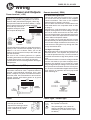
Disconnect Battery
Before starting the installation, always disconnect
the negative terminal of
the battery.
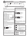
DLS logo on amplifier cooling flange
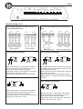
The DLS logo on top of the amplifier is attached
with two 1 mm hex. screws. The logo can be removed and twisted 90 or 180 degrees, and then
screwed back in wanted position. The logo can be
mounted in four different ways to match your installation.
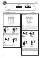
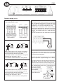
Removal of side flanges
In order to fasten the amplifier to the surface and
connect speaker and power cables, the flanges on
the sides must be removed. This is done by
loosening the hex screws on top of the amplifier.
Use a 3 mm hex key.
Remove
these
screws using a 3
mm hex. key for
removal of side
flange. Remount
after fastening the
amplifier
and
connection of the
speaker and power
cables.