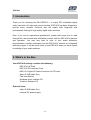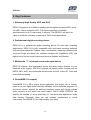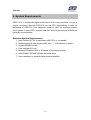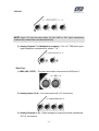
1
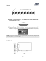
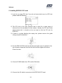
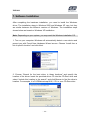
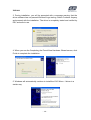
ESP1010
Second Edition Jan., 2005
Index
1.
2.
3.
4.
5.
Introduction
What’s in the Box
Key Features
System Requirements
Exterior Features
2
2
3
4
5
1. Rack
5
2. PCI Card
7
3. I/O Cable
8
6. Hardware Installation
9
1. Preparation for hardware installation
9
2. Installing the ESP1010 PCI card
10
7. Software Installation
8. ESP1010 Panel
11
16
1. File
16
2. Config
17
3. DirectWIRE 3.0
17
4. Control Panel
17
5. Mixer Panel
20
6. About
20
9. Configuring ESP 1010
21
1. Windows Multimedia Setup
21
2. 5.1 Surround Sound for DVD Player Applications
21
3. ASIO 2.0 Applications
22
4. Sonar
24
5. WaveLab 4.0
24
10. DirectWIRE 3.0
25
1. What is DirectWIRE?
25
2. DirectWIRE Panel
25
3. DirectWIRE Examples
27
11. Specifications
12. Warranty
29
31
-1-
ESP1010
1. Introduction
Thank you for choosing the ESI ESP1010 – a unique PCI multimedia digital
audio card with a full size rack-mount interface. ESP1010 has been designed to
provide many powerful functions that will satisfy both beginners and
professionals looking for high quality digital audio solutions.
Even if you are an experienced professional, please take some time to read
through this user manual and familiarize yourself with the ESP1010’s features
and operation. You may also want to refer to your audio software’s
documentation to better understand how the ESP1010’s features are integrated
with the program. It will be much easier to use ESP1010 when you have a good
knowledge of your audio software.
2. What’s in the Box
Your ESP1010 package contains the following:
· ESP1010 19” Rack
· ESP1010 PCI Interface Card
· MIDI I/O, Digital I/O Cable Connector for PCI card
· 44pin D-SUB cable (2m)
· This User Manual
· Windows driver software CD
· Tracktion Software CD
Optional items:
· 44pin D-SUB cable (5m)
· external DC power supply
-2-
ESP1010
3. Key Features
1. Extremely High Quality ADC and DAC
ESP1010 supports up to 96kHz sampling rate for digital recording (ADC) and a
full 24Bit / 96kHz resolution DAC. Full duplex operation is available
simultaneously for all 10 inputs and 10 outputs. The ESP1010 will prove its
value in multitrack recording, mastering or DVD Audio applications.
2. Professional digital recording device
ESP1010 is a professional digital recording device for hard disk recording
applications. ESP1010 is fully compatible with multi-track recording software
such as Sonar/Cakewalk, Cubase, Logic, and Nuendo; mastering software such
as Sound Forge and Wave Lab; software samplers like GigaStudio, EXS, and
Halion and of course virtual instruments such as Reason and Reaktor.
3. Multimedia / 7.1 channels surround sound device
ESP1010 delivers ultra high-quality sound and adds unique features to your
Windows audio system. ESP1010 supports all popular audio formats such as
MPEG, MP3, WAV, and multimedia formats such as DVD, Video CD, Flash and
Internet Broadcasting.
4. DirectWIRE 3.0 support
DirectWIRE 3.0 is ESI’s unique driver application that allows you to virtually
patch all of your digital audio internally between various software programs. In
this latest version, support for patching hardware inputs and mixing multiple
audio streams at the inputs has been added. With E-WDM, ESP1010 can
simplify the hassles of wiring externally for inter-driver/inter-application audio
data transfer. Especially when you use software synthesizers or virtual
instruments, DirectWIRE 3.0 will help simplify your setup.
-3-
ESP1010
4. System Requirements
ESP1010 is a multimedia digital audio device with many functions, not just a
simple soundcard. Although ESP1010 has low CPU dependability, to take full
advantage of ESP1010, your computer needs to meet the minimum system
requirements. A faster CPU, a faster hard disk, and a higher amount of RAM are
generally recommended.
Minimum System Requirements
1. Intel Pentium III CPU or equivalent AMD CPU or compatible
2. Motherboard with Intel chipsets (BX, i8xx, ..), VIA chipsets or others
3. At least 256MB of RAM
4.
5.
6.
7.
One available PCI slot
Microsoft Windows 2000 or Windows XP operating system
Ultra DMA66/100 and 5400rpm hard disk drive
Active speakers or speakers with powered amplifier
-4-
ESP1010
5. Exterior Features
1. Rack
- Front Part 1) MIC. +48V
①(In1~2) –XLR MIC input 1 ~2 ports
②(+48V) – Phantom power switch
WARNING: To use the +48V Phantom power supply, you need to connect an
optional external power supply to the ESP1010 rack.
WARNING: To prevent loud clicking via your monitor speakers, do not connect
your microphone while Phantom power is turned on.
WARNING: To prevent loud clicking via your monitor speakers, please turn off
the “MIX OUT” button on ESP1010 software panel when you connect an
external device to the inputs, especially a microphone.
2) Analog Inputs (1~4) - line input ports for Input 1~4.
-5-
ESP1010
NOTE: Input 1/2 can be used either via the XLR or 1/4” input connectors,
however they cannot be used simultaneously.
3) Analog Outputs 7~8 (Headphone outputs) – Two 1/4” TRS phone jack
type headphone connectors for output 7 / 8.
- Rear Part 1) MIDI (IN2, OUT2) – The input and output connectors for MIDI port 2.
2) Analog Inputs (5~8) – Line input ports with 1/4" connectors.
3) Analog Outputs (1~8) – Eight analog line output ports with unbalanced
TS 1/4” connectors.
-6-
ESP1010
4) D-SUB – Connect to 44pin D_SUB cable (Do not use any cable except
the original cable by ESI).
5) External Power – DC9~12V 300mA. You must connect an external DC
adaptor if using +48V Phantom power. Please always check the polarity.
NOTE: To prevent damage to your equipment, do not use a DC adaptor with
less than 300mA or more than 12V..
2. PCI Card
-7-
ESP1010
1) D-Sub Connector – Connects ESP1010 PCI card with the Rack
2) Cable Connector – Connects with included MIDI I/O and coaxial digital
I/O cable
3) Digital Optical Output – Digital output via optical connector
3. I/O Cable
1) Connector – Connects to ESP1010 PCI card’s cable connector
2) DIG I/O - Coaxial digital (S/PDIF) input and output connectors
3) MIDI I/O - MIDI connectors for input and output of MIDI port 1
-8-
ESP1010
6. Hardware Installation
ESP1010 requires multiple installation steps:
· PCI card installation, rack connection
· Driver installation
After the hardware installation is finished, you can start connecting external
devices such as microphones, amplifiers, a mixer, MD- or DAT-players, etc. to
the unit.
1. Preparation for hardware installation
The ESP1010 PCI card and other components in the computer could easily be
damaged by electrical shocks. You need to use an anti-static device that can
discharge the static electricity of your body to avoid potential static damage to
the cards.
1) ESP1010 PCI card is packaged in an anti static plastic pouch. Do not
open the pouch until you’re ready to install the card.
2) Turn off the computer and remove the power cable from your computer’s
power supply.
3) Remove the cover. Make sure that you have an available PCI slot in your
motherboard to install ESP1010. Please refer to your computer’s user
manual on how to remove the cover.
4) To avoid possible static shock to the computer parts, discharge it by
touching the computer case or something grounded. We recommend
you to use an anti-static device such as an anti-static wrist band.
5) When you need to hold the ESP1010 PCI card, please hold it on the
edge of the card. Do not grab the card by touching the board.
-9-
ESP1010
2. Installing ESP1010 PCI card
1) Look for an empty PCI slot. If you do not know which one is a PCI slot,
please read the following:
2) The PCI slot is the most common and is used for a wide range of
devices from the soundcard to the modem. Usually, the PCI slot is the
white-colored slot. It should not be too hard to find the PCI slot for
ESP1010.
3) If there is a guide blocking the empty slot, please remove the guide
using a proper screwdriver.
4) Put the ESP1010 PCI card into the slot and make sure it is placed in the
slot correctly. Insert the card into the slot and then tighten the screw.
Close the case.
5) Connect D-SUB cable from PCI card to Rack box.
6) Connect the I/O cable’s connector to the ESP1010 PCI card.
- 10 -
ESP1010
7. Software Installation
After completing the hardware installation, you need to install the Windows
driver. The installation steps in Windows 2000 and Windows XP vary, but they
are similar between the different versions of Windows. The installation steps
shown below are based on Windows XP installation.
Note: Depending on your system, you may need the Windows installation CD.
1. Turn on your computer. Windows will automatically detect a new device and
prompt you with Found New Hardware Wizard screen. Choose “Install from a
list or specific location” and click Next.
2. Choose “Search for the best driver in these locations” and specify the
location of the driver. Insert the provided driver CD into the CD-Rom drive and
select “Include this location in the search” and click Browse to find the driver’s
location. For example, it is D:\ESI\driver\esp1010\, if D:\ is your CD-Rom drive.
- 11 -
ESP1010
3. During installation, you will be prompted with a message warning that the
driver software has not passed Windows Logo testing. Select Continue Anyway
and proceed with the installation. The driver is completely tested and verified by
ESI, and safe to use.
4. When you see the Completing the Found New Hardware Wizard screen, click
Finish to complete the installation.
5. Windows will automatically continue to install the 1010 Wave -1 driver in a
similar way.
- 12 -
ESP1010
6. If asked again, choose “Search for the best driver in these locations” and
specify the location of the driver. Select “Include this location in the search” and
click Browse button to find the driver’s location. For example, it is
D:\ESI\esp1010\, if D:\ is your CD-Rom drive.
7. During installation, you will again be prompted with the Windows Digital
Signature warning screen. Once again, select Continue Anyway and proceed
with the installation.
8. Once the installer has finished copying the files. You will see the Installation
Complete screen. Click Finish.
- 13 -
ESP1010
9. After you complete both driver installations, you should restart your computer.
10. After restarting Windows, you will see the ESP1010 panel icon in your
system tray (lower right corner of your desktop). Click on the icon to open the
ESP1010 panel.
11. Go to Device Manager, check the devices under ‘Sound, video and game
controllers’. You will see the 1010 Controller and 1010 Wave -1 if you have
completed the installation process correctly. Your ESP1010 is ready to use.
NOTE: There is another way to install driver easily under Windows 2000 and
XP. Just launch “autoinst.exe” from the driver directory. Just press “ Continue
Anyway” button on the “ Windows Digital Signature warning screen” during
Installation. The whole driver package will be installed automatically.
- 14 -
ESP1010
12. Go to Control Panel → Sounds and Audio Device Properties → Audio tab.
You can choose each stereo device or multi device for your propose on Sound
playback or Sound recording as default device (e.g. used to playback the
Windows system sounds). And also you can choose the defailt MIDI port.
NOTE: You can see 2 MIDI devices on MIDI Music Playback item of Sounds
and Audio devices properties. “1-1010 MIDI 1” device is for I/O cable which
connected PCI card. And “2-1010 MIDI 2” device is for Rack MIDI interface.
- 15 -
ESP1010
8. ESP1010 Panel
The ESP1010’s driver software provides a simple yet powerful interface with
your computer. The panel gives you a multi-channel software mixer for ten
playback channels from your audio software and the input channels from the
hardware inputs.
The ESP1010 panel is installed in your system when you complete the driver
installation. To open the panel, double click the
in the system tray.
icon, which is the ESI logo,
While the ESP1010 panel gives you great deal of control, you may find that the
default settings work just fine for your needs. Just to be safe, though, we’ll cover
all the features of the panel in detail.
The ESP1010 panel features pull down menus for configuration.
1. File
1) Close Windows (ALT-F4): Closes the ESP1010 panel window. Note that
this does not shut down the panel. You may open the panel again by
clicking the
icon in the system tray.
2) Exit: Shuts down the ESP1010 panel completely.
- 16 -
ESP1010
2. Config
1) Mouse Wheel: Configures the mouse wheel for volume change
adjustment. Default value is ±1.5dB per step. You can configure the
steps to your preference.
Configuration
Step 1
Step 2
Step 3
Step 4
Change/Step
±1.5dB
±3.0dB
±6.0dB
±12.0dB
2) Latency: Configures the latency setting for ESP1010. Generally, for
multi-track recording we recommend higher latency for stability. For
software synthesizers, we recommend lower latency. The optimal latency
setting will depend on your application and your computer system.
3) Factory Default: Allows you to revert back to the factory default setting
for all configurations.
4) Always On Top: This enables the ESP1010 panel to be always
displayed on the top.
5) Clone 4-way from Out 1,2: This enables same signal output from
output 1,2 to whole channels.
3. DirectWIRE 3.0
Clicking this menu will open the DirectWIRE 3.0 screen. DirectWIRE 3.0 is a
unique feature of the E-WDM driver that transfers digital audio data internally
within different applications. MME, Multi-MME, ASIO and GSIF indicate the
different drivers supported by ESP1010. The numbers along the column
designate the channel number of the inputs and outputs.
Please refer to Section 10, Using DirectWIRE 3.0 on page 25 for more detailed
instructions and examples on using DirectWIRE 3.0.
4. Control Panel
You can come back to the panel control screen by clicking this menu. It is also
the default screen you see when you first launch the panel. Basic functions of
ESP1010 are controlled from this screen.
1) INPUT: You can change the input signal level on all channels by clicking
and dragging the fader bar. The number on the bottom shows the relative
amount in dB. Clicking this number enables you to mute the channel.
- 17 -
ESP1010
You can control gain from -60dB to +15dB (0.5dB per step) on input ch
1/2. Input 1/2 allows you enable +12V phantom power when using a
micrpphone. To use it, you must change the input level to “M”
(microphone) from “L” (line input). After selecting “M”, you can select “12”
(12V) on each channel for phantom power. Note: if your microphone
requires 48V phantom power, you can enable that on the hardware when
an optional external power supply is connected to the ESP1010 rack. It is
not recommended to enable both +12V and +48V phantom power
simultaneously.
2) OUTPUT: You can change the output monitoring level for all channels
(1~8, S/PDIF) by clicking and dragging the fader bar. The number on the
bottom shows the relative amount in dB. Clicking this number enables
you to mute the channel.
- 18 -
ESP1010
H·P: The signal from channel 1/2 can be sent to the headphone outputs.
MIX OUT: Send out the mixer signal to output 1/2 and/or the S/PDIF
output. Please refer to section 5 on page 20, for more information on the
Mixer Panel. You can send the mix to the headphones as well, when H P
is enabled.
S/PDIF PRO/CON: ESP1010 can transmit digital information in either of
two formats, Pro (professional / IEC60958 Type I) and Con (consumer /
IEC60958 Type II).
3) MASTER: You can adjust all input / output monitoring levels by clicking
and dragging the fader in the master control panel. Again the number on
the bottom shows you the relative monitoring level in dB. Clicking this
number enables you to mute the channel.
LINK: You can control volume of left and right channels independently by
deselecting this button.
4) S / R: You can configure the sampling rate in this panel.
Auto: Automatically sets the sampling rate to your audio file’s sampling
rate.
22~96: You can set the sampling rate manually from 22kHz to 96kHz.
5) MASTER CLOCK: Allows you to choose the digital clock source for
- 19 -
ESP1010
ESP1010.
INT: Sets the ESP1010’s internal clock as the master clock. This is the
recommended default setting.
EXT: When ESP1010 receives digital data from an external digital device
through S/PDIF coaxial digital input, the ‘LOCKED’ indicator will tell you
that ESP1010 is receiving the data. You can then select EXT to use the
incoming digital audio data as the clock source. The external device
becomes the master and ESP1010 becomes the slave.
5. Mixer Panel
Clicking this menu opens the mixer screen of ESP1010 panel.
You can control panning, mixing and mute within this screen.
6. About
You can check the version information of the current driver.
- 20 -
ESP1010
9. Configuring ESP1010
ESP1010 is a premium multimedia audio device for professional audio. It is
simple to configure ESP1010 for use in games to DVD surround sound. You can
also configure ESP1010 for hard disk recording using professional digital audio
software. This chapter includes the setup guide for some common applications.
ESP1010 supports applications that use WDM, MME, ASIO, GSIF and Direct
Sound.
NOTE: Only the basic setup options for the applications are shown in this
chapter. For more detailed setup options please refer to the manual of your
software.
1. Windows Multimedia Setup
To configure ESP1010 for multichannel Windows multimedia applications:
Go to Control Panel → Sounds and Audio Device Properties → Audio tab.
Select “6-1010 Multi-10ch” driver as your playback device.
2. 5.1 Surround Sound for DVD Player Applications
To configure ESP1010 for 5.1 channel surround sound DVD player:
Go to Control Panel → Sounds and Audio Device Properties → Audio tab.
Select “6-1010 Multi-10ch” driver as your playback device.
NOTE: You must check that the DMA access is enabled for your DVD-Rom
drive settings. If not, you may get drop-outs during DVD playback.
Set speaker configurations in your software DVD player to “6 Speaker.” You’re
ready to enjoy DVD with 5.1 channel surround sound.
This is an example of 5.1 channel surround sound route for ESP1010. The
order may vary for different versions of Windows.
ESP1010
Output
Speaker
1
2
3
4
Front
Front
Center
Woofer
- 21 -
5
6
Surround Surround
ESP1010
Left
Right
Left
Right
Some applications like PowerDVD 5.0 supports 8 channel surround speaker
outputs as shown below. However, most of DVD titles only have 5.1 surround
sounds. You can enjoy Dolby Digital DVD with just 6 speaker setting.
3. ASIO 2.0 Applications
1. Tracktion
After launching Tracktion from Mackie (included on a separate CD), go to
Settings → Audio Devices → Wave Device. Select “ASIO 2.0 – ESI1010” as
ASIO device.
- 22 -
ESP1010
2. Nuendo or Cubase SX / SL / SE
After launching Nuendo or Cubase, go to Device → Device Setup → VST
Multitrack. Select “ASIO 2.0 – ESI1010” as ASIO device and “ESI1010 Clock”
as Audio clock source.
3. Logic
After launching Logic, go to Options>Preference > Audio Driver 2 and check
“ASIO”. Select “ASIO 2.0 – ESI 1010” as ASIO device.
- 23 -
ESP1010
4. Sonar
Sonar either supports ASIO (recommend, from Sonar 2.2 and newer) or
WDM/KS. You can select the driver type under Options → Audio Options→
Advanced. If you use ASIO, select “ASIO 2.0 – ESI 1010” as ASIO device. If
you use WDM/KS, you can select the MME devices “1-1010 1/2 ~ 7/8ch” or the
“Multi-10 ch” WDM device.
- 24 -
ESP1010
5. WaveLab 4.0
After launching WaveLab, go to Options → Preferences → Audio Card.
Choose one of “MME-WDM 1-1010 “1/2ch ~ 7/8ch as Playback and Record
device. WaveLab supports ASIO2.0 driver also.
10. DirectWIRE 3.0
1. What is DirectWIRE?
DirectWIRE is a 100% purely digital wire!
DirectWIRE is a driver technology, developed by ESI, which can be used for
routing audio streams internally within applications using E-WDM Audio MIDI
drivers, exclusively developed by ESI.
With the DirectWIRE router, an application can record from other application’s
audio outputs without external wiring or any loss of data while they are running
at the same time.
DirectWIRE also allows you to easily rip any audio stream in real time by
transferring data through DirectWIRE from MP3s, live On-line Broadcasts, OnDemand content, and more.
- 25 -
ESP1010
2. DirectWIRE Panel
Click on DirectWIRE on the ESP1010 panel. The DirectWIRE panel window as
shown below will appear.
The number along the row represents the number of the input or output port.
The columns represent inputs and outputs (on and off) of the respective drivers.
Patch the virtual cables from one point to another as you drag your mouse.
INPUT column is a new feature of DirectWIRE 3.0. It's used to route signals
from the card's hardware inputs. With ESP1010, from INPUT 1 to 8 are identical
to the each left and right channels of the analog input signal. And INPUT 9 and
10 are the left and right channels of the digital input.
MME column represents general application's I/O:
Ex.) WinAmp, WaveLab (non ASIO mode), Cakewalk, Audition, Vegas, etc.
WDM column represents Multi-MME application’s I/O:
Ex.) SONAR (WDM/KS mode), PowerDVD, WinDVD, etc.
ASIO column represents ASIO application’s I/O:
Ex.) Cubase, Logic, Reason, Nuendo, SONAR (ASIO mode), Samplitude, etc.
GSIF column represents GSIF applications like GigaStudio.
NOTE: Some applications support multiple driver modes.
- 26 -
ESP1010
3. DirectWIRE Examples
NOTE: Please setup DirectWIRE before you start your audio applications.
1) Recording from WinAmp(MME) to WaveLab(MME)
Caution; If you want to record what's played back in Winamp, but don't
want to hear the sound, you should click the OUT button in the MME
section so that it changes to “OUT”
2) Recording from WinAmp(MME) to SONAR(WDM)
3) Recording from WinAmp(MME) to Cubase, Logic, Nuendo(ASIO)
- 27 -
ESP1010
4) Recording from GigaStudio(GSIF) to SONAR(WDM)
5) Recording from GigaStudio(GSIF) to Cubase(ASIO)
6) Let's say you want to quickly dub some vocal over an audio track. It's
very simple with DirectWIRE 3.0. You just have to make connections
similar to these.
- 28 -
ESP1010
11. Specifications
<Analog Audio>
1. Analog Inputs
1) Connector Type:
1/4" female TRS-type, balanced or unbalanced (ch 1~8)
2) Peak level:
0dBFS @ +6.5dBV (-10dBV nominal)
3) Impedance:
10k ohms minimum
4) Att. & Gain Control:
-60dB ~ +15dB (0.5dB step size) *ch1, 2ch only
2. Analog Ouputs
1) Connector Type:
1/4" female TS-type, unbalanced (ch 1~8)
2) Peak level:
+6.2dBV @ 0dBFS (-10dBV nominal)
3) Impedance:
100 ohms
4) Attenuation Control:
-60dB ~ 0dB (0.5dB step size)
3. Mic Preamplifier
1) Peak level:
0dBFS @ -40dBV
2) Gain Adjustment:
Gain +31dB up + -60 ~ +15dB (0.5dB step size)
3) +12V phantom power supply from PCI Card
+48V phantom power supply from RACK (XLR connector only)
4. Headphone Amplifier
1) Load Impedance Range:
32-300 ohm (for the best performance)
2) Output Power:
125mW @ 32ohm per channel
<Digital Audio>
- 29 -
ESP1010
1. Internal 20ch /36-bit Digtal Mixer(Input 10ch/Output 10ch)
2. Sample rate supports:
(22.05,24)*,32,44.1,48,88.2,96kHz : *analog only
3. A/D Converter
1) Signal to Noise Ratio:
107dB (A-weighted) @ fs=48kHz
2) Dynamic Range:
107dB (-60dBFS with A-weighted) @ fs=48kHz
3) S/(N+D)(-1dB):
100dB @ fs=48kHz
4) Interchannel Isolation:
-110dB
5) Resolution:
24-Bit
4. D/A Converter
1) Signal to Noise Ratio:
112dB (A-weighted) @ fs=44.1kHz
2) Dynamic Range (S/N):
112dB (60dBFS with A-weighted) @ fs=44.1kHz
3) THD+N:
-94dB @ fs=44.1kHz
4) Interchannel Isolation:
-100dB
5) Resolution:
24-Bit / 96kHz
5. Digital Input
1) Connector Type:
RCA (provided via I/O cable)
2) Format:
IEC-60958 Consumer (S/PDIF coaxial)
3) Sampling Rate:
44.1,48,88.2,96kHz
4) Resolution:
24-Bit
6. Digital Output
1) Connector Type:
RCA (provided via I/O cable), Optical (on board)
2) Format:
IEC-60958 Consumer (S/PDIF coaxial)
3) Sampling Rate:
44.1,48,88.2,96kHz
4) Resolution:
24-Bit
<MIDI>
7. MIDI I/O
1) 2-in, 2-out; 32 MIDI channels in and out
2) Connector Type:
MIDI1-
Standard MIDI 5-pin DIN (provided via I/O cable)
MIDI2-
Standard MIDI 5-pin DIN (provided via Rack)
- 30 -