1
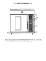
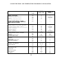
RANGE TOP CONVECTION OVEN
MODEL OC-4T
INSTRUCTIONS
Installation
Operation
Maintenance
WELLS MANUFACTURING COMPANY
P.O. BOX 280 VERDI, NEVADA 89439 (702) 345-0444
FAX (702) 345-0569
ITEM NO. 48818 - 10/93
Date 8/03/00
WELLS MANUFACTURING COMPANY
PARTS LIST: SP12S
ILLUS.
# PART NO.
ELEMENTS:
501120
501450
50293
502991
63866
63872
68882
68884
68885
PAGE
1 RKPSTD04
SERV PART OC-4T OC-4TC OC-4HC
DESCRIPTION
ELEM HC-125 225
ELEM (FRENCH PLATE) 2KW 240V
ELEM 240V 2600W HOT PLATE
KIT OC4HC CONVERTS TO OC4T CI
ELEM 208V 2500W CTR 4IN SP
ELEM 208V 2500W INNER 2.5IN SP
ELEM RANGE 480V 2600W
ELEM 480V CTR OC-4T
ELEM 480V INNER OC-4T
CONTROLS (THERMOSTATS & INFINITE SWITCHES):
50562
INFINITE SWITCH INF-240-277
67438
CONTROL TEMP/TIME 5-PROG OC-1
68889
SWITCH INFINITE 240V PILOT DTY
KNOBS:
68705
KNOB RANGE (INF SW) OC-4T
SWITCHES (ROCKER & TOGGLE):
65651
SWITCH DPDT 250V 15A ON/OFF
65657
SWITCH FAN 2 SPD
MISC. ELECTRICAL:
501122
51157
54769
54871
57465
60877
63880
63932
65180
65239
65655
65847
67550
68862
69823
83439
MISC. MECHANICAL:
500872
LIGHT HOT SURFACE HC 240V
LIGHT SIGNAL RED 240V
FUSEHOLDER HPA-EE 10A 240V
FUSE SC-10 34768 BOX OF 4
TERM BLOCK MAIN 85AMP
LIGHT SIGNAL WHITE 250V
RELAY DPDT M4200-2
MOTOR 2SP 1/4HP 208/240V OVEN
SNAP DISC THERMOSTAT M4200/OC1
PROXIMITY SWITCH ASSY OVENS
RELAY MERC 2 POLE 208/240V 35A
RELAY MERC SINGLE POLE 20A
PROBE ASSY TEMP OC-1
TRANSFORMER 480 TO 240X.5KVA
CAPACITOR MOTOR START 440V
VALVE SOLENOID SINGLE
LABEL HOT SURFACE IEC STD 417
Date 8/03/00 WELLS MANUFACTURING COMPANY PAGE 2 RKPSTD04
PARTS LIST: SP125
SERV PART OC-4T OC-4TC OC-4HC
ILLUS.
# PART NO.
MISC. MECHANICAL:
501110
501124
503252
63767
63768
63785
63787
63797
63804
63817
63834
63860
63886
63887
63896
63899
63900
63912
63946
63948
64591
65050
65598
65647
68703
HARDWARE:
500102
51040
51053
51731
54285
55487
60329
60680
60821
61048
61244
63889
ACCESSORIES:
21330
21372
21373
21376
21705
21950
22226
22445
DESCRIPTION
CERAMIC GLASS HC-225 2256
CREME CLEANING HC-125 225
GASKET CLOSE CELL, OVEN POT OC
DOOR ASSY W/WINDOW OC-1
DOOR OUTER WRAP M4200
SUPPORT OVEN RACK M4200
REED SWITCH BRACKET M4200
WHEEL BLOWER M4200
TRIM FR LOWER M4200
DOOR GSKT TOP & BOT M4200
GASKET ELEM M4200/OC-1
BRKT DOOR HINGE TOP M4200
WINDOW ASSY M4200
PIN DOOR HINGE TOP M4200
BRKT DOOR HINGE BTM M4200
COVER DOOR PIN M4200-2
SLEEVE DOOR HINGE BTM M4200
PIN DOOR HINGE BOTTOM M4200
HANDLE & LATCH ASSY M4200
MAGNET PERMANENT
PLATE MTG MAGNET M4200
GRIP HANDLE M4200
LEG ADJUST 6lN OC-1
SHIELD PROX SWITCH OC-1
DECAL OC-4T
STRAIN RELIEF CONVECT OVENS
GROMMET INSULATION 7/8D
NUT KEP 8-32 PK100
SCREW TRS PHL 8-32X11/16
SCREW FLT 8-32X3/8 LG 100DPK50
SCREW TRS PHL 8-32X5/16 PK 50
SCREW RND PHL NI 6-32X7/8 PK10
NUT KEP SS 10-32 PK10
SCREW FLT SS 10-32 X 1 1/2
BOLT HEX 1/4X20-3/4
BUSHING INSULATOR 1 3/8IN
CLIP RACK SUPPORT M4200
CASTER SET CONVECTION OVEN
CASTER SWIVEL W/BRAKE M4200
CASTER SWIVEL W/0 BRAKE M4200
RACK OVEN M4200
DRIP TRAY H-63/65
RACK OVEN M4200 10 EA
LEG KIT OVEN, S/S SET OF 4 PCS
SCAPER CLEANING CERMAIC HP
WARRANTY STATEMENT
All commercial cooking equipment manufactured by WELLS is warranted against defects
in materials and workmanship for a period of one year from the date of original
installation or 18 months from the date of shipment from our factory, whichever comes
first and is for the benefit of the original purchaser only, except that;
a.
with respect to the stainless steel fry pots for gas fryers, model
number WFG-40-2, the stainless steel fry pot is warranted to be free from
defects that could cause shortening leaks for five years from date of
purchase, except that after one year replacement of fry pot only is
covered at 75% of list price of kettle assembly. Fry kettle includes new
shrouds, insulation, flue vent, burners, thermostats and attaching
hardware; travel and labor not included. Fry pots which fail due to
abuse are not covered by standard or five year warranty items include
but not limited to firing of burners without shortening or other
cleaning solution in the fry kettle at proper level.
b.
with respect to Lite Line Products, warranty is one year parts and labor
on carry—in portable models.
THIS WARRANTY IS THE COMPLETE AND ONLY WARRANTY, EXPRESSED OR IMPLIED IN LAW OR
FACT, INCLUDING BUT NOT LIMITED TO, WARRANTIES OF MERCHANTABILITY OR FITNESS FOR ANY
PARTICULAR PURPOSE, AND/OR FOR DIRECT, INDIRECT OR CONSEQUENTIAL DAMAGES IN
CONNECTION WITH WELLS’ PRODUCTS. This warranty is void if it is determined that upon inspection by an
authorized service agency that the equipment has been modified, misused, misapplied, improperly
installed, or damaged in transit or by fire, flood or act of God. It also does not
apply if the serial nameplate has been removed or service is performed by
unauthorized personnel. The prices charged by Wells for its products are based upon
the limitations in -this warranty. Seller’s obligation under this warranty is limited
to the repair of defects without charge by a WELLS’ factory authorized service agency
or one of its sub—service agencies and is limited to a 60 mile radius to the nearest
authorized service agency or one of its sub—service agencies. This service will be
provided on customer’s premises for non—portable models. Portable models (a device
with a cord and plug) must be taken or shipped to the closest authorized service
agency, transportation charges prepaid for service. In addition to restrictions
contained in this warranty, specific limitations are shown in the Service Policy and
Procedure Guide. WELLS’ authorized service agencies are located in principal cities.
This warranty is valid in the United States and Canada and void elsewhere. Please
consult your classified telephone directory, your foodservice equipment dealer or
write the Factory Service Department, Wells Manufacturing Company, P.O. Box 280,
Verdi, Nevada 89439, phone (702) 345—0444, for information and other details
concerning warranty.
—
3
SHIPPING CLAIM PROCEDURE:
For your protection, please note that equipment in this shipment was carefully
inspected and packed by skilled personnel before leaving the factory. The
transportation company assumes full responsibility for safe delivery upon acceptance
of this shipment.
IF SHIPMENT ARRIVES DAMAGED:
1.
VISIBLE LOSS OR DAMAGE: Be certain this is noted on freight bill or express
receipt and signed by person delivering.
2.
FILE CLAIM FOR DAMAGES INKEDIATELY: Regardless of extent of damage.
3.
CONCEALED LOSS OR DAMAGE: If damage is unnoticed until merchandise is
unpacked, notify transportation company or carrier immediately, and file
“concealed damage” claim with them. This should be done within (15) days of
date of delivery is made to you. Be sure to retain container f or inspection.
We cannot assume responsibility for damage or loss incurred in transit. We will,
however, be glad to furnish you with the necessary documents to support your claim.
ELECTRICAL SPECIFICATION INFORMATION:
OC-4T Range top Convection Oven:
*
Voltage: 208V, 240V or 480V three phase only.
AMPS THREE
VOLTS
240
L1
36.8
39.2
480
19.3
19.3
208
4
RENA CORD SET
PHASE
L2
36.8
39.2
L3
34.8
37.4
18.3
15-60P
15—60P
L16—30P
KILOWATT
OVEN
HOTPLATE
5.0
5.6
5.6
8.0
10.4
10.4
TOTMI
13.0
16.0
16.0
WELLS RANGE TOP OVEN MODEL NO. OC-4T
CONTROLS AND FUNCTIONS
1. INFINITE SWITCHES (4 pcs) - Control corresponding range top element from "OFF" to "HIGH" heat
2. RANGE TOP ELEMENT SIGNAL LIGHT (4 PCS) WHITE - These are indicator lights that stays "ON"
continuously when the infinite switch is turned other than the "OFF" position.
3.
OVEN POWER LIGHT (RED) This light indicator is “ON” whenever power is
available for the oven elements and/or oven blower motor.
4.
HEAT ON LIGHT (WHITE) This light indicator comes “OW’ simultaneously with the
oven elements.
5.
OVEN POWER SWITCH A three (3) position rocker switch. The top position will
bring power available to oven elements and blower motor. Middle position, will
turn power “OFF” to the oven only. Bottom position, will turn the power
available to the blower motor continuously.
6.
FAN SPEED SWITCH This turns the blower motor to high or low speeds.
7.
TIME & TEMPERATURE (SOLID STATE) CONTROL Controls oven temperature, and
equipped with Audio Alarm when a timing cycle is lapsed. Refer to operating
instructions on page 9 for details.
6
-
-
-
-
-
FOR YOUR SAFETY
Wells “Prospector” Ovens are equipped with a grounded four— prong electrical
plug. This four-prong plug is part of a system that will protect you in the
event of an electrical problem in the appliance. Be sure the four—prong plug
is plugged into a matching four-prong socket. DO NOT cut or break off the
large fourth prong in this plug, or the protective system will not work.
IMPORTANT
Make sure incoming voltage is the same as unit is rated for. An electrical
specification plate specifying rated voltage, wattage, HZ and phase of unit
is attached to the oven.
Plugging oven into greater voltage than unit is rated for may cause severe
damage to the thermostat, infinite control, elements and other components.
Plugging oven into less voltage than unit is rated for may cause significant
decrease in performance.
CAUTION
DO NOT SPLASH OR POUR WATER ONTO CONTROL PANELS OR WIRING.
7
INSTALLATION INSTRUCTIONS:
CAUTION:
1.
2.
3.
4.
5.
6.
7.
8.
Installation should be done by a qualified service technician.
Remove Oven carefully from carton.
IMPORTANT: Read all installation instructions carefully BEFORE starting installation.
Carefully place the oven on its side, and thread legs or casters into the matching
threaded holes on the bottom of the oven. Place the two casters with brakes at
the front of the unit, and the remaining two at -the- rear.
Raise the oven to an upright position, and adjust the feet to level the oven
from front to back and side to side.
For field wired range, install field wiring box below the level of the top
elements.
It is the responsibility of the installer to comply with local codes.
Plug unit into a grounded three phase receptacle.
THAT INCOMING VOLTAGE IS THE SAME AS UNIT IS RATED FOR.
Any installation not matching the specification discussed in this manual will
void the oven’s warranty.
OPERATING INSTRUCTIONS FOR 8 KEY SOLID STATE CONTROL:
Manual Cook Mode:
1.
2.
3.
4.
5.
Rotate “Temp’1 knob to the desired cooking temperature (range
100° to 500°F). A clockwise rotation will increment the temperature in 5F
intervals. Counterclockwise rotation will decrement the temperature display.
The oven will start heating as soon as the set temperature is higher than the
oven temperature. The temperature digits will flash and display the set
temperature until the oven reaches the set temperature. Upon reaching the set
temperature, these digits become static.
The oven may be turned of f without placing the main power switch in the of f
position by rotating the “TEMP” knob counterclockwise until zero degrees is
shown in the display.
Rotate “Time” knob to the desired cooking time (range 5 seconds to 12 hours).
A clockwise rotation will increment time and a counterclockwise rotation
decrement time. The time display digits and colon will flash when time is set,
but the timer is not started.
To start the timer, press the “Start Timer” key. The timer digits become
static during the countdown period but the colon continues to flash.
At the end of the time cycle, an audible alarm will sound. By pressing the
“Cancel” key, the audible alarm will be shut off.
8
Program Cook Mode:
1.
Five programmable keys are provided f or presetting a time and temperature f
or each “PGM” key. To set the program, press and hold the appropriate “PGM”
key
(1—5) and turn the “Time” and “Temp” knobs to the desired time and temperature.
When the “PGM” key is released, the displayed time and temperature is stored
in memory.
2.
The program for any “PGM” key may be recalled and displayed by momentarily
pressing the “PGM” key.
3.
To start a cook cycle, press the appropriate “PGM” key and the “Start Timer”
key. Once the cook cycle has started, the program keys and rotary “Time” and
“Temp” knobs are locked out to prevent accidental re—programming.
4.
The actual oven temperature can be recalled by pressing the “Actual Temp” key.
5.
At the end of the cook cycle, an audible alarm will sound. Press the “Cancel”
key to shut of f the audible alarm.
Temperature Offset Mode:
A user preference offset mode is provided when you feel oven cooks is too hot or too
cold. This mode can be used to adjust oven controlling temperature by +1- 35F in 50
increments. This adjustment affects the entire cooking range.
ACCESS:
1.
Set the time digits of the control to 00:00.
2.
Set the temperature between 400° and 500°F.
3.
Push and hold the start/timer key for 5 seconds.
4.
Turn either rotary dial until desired off—set is
displayed.
5.
Push the actual temp key to exit.
Preheat Instructions:
1.
Set the ON-OFF-FAN switch to the ON position. The red light will indicate that
the power is on.
2.
Turn -the thermostat knob to the desired temperature. The yellow light will
indicate that the heating elements are on.
3.
When the yellow light goes off, the oven has reached the desired temperature
and is ready for use.
CLEANING INSTRUCTIONS:
1.
Turn temperature control knob to the OFF position.
CAUTION:
Make sure the oven has cooled down to 150° F or below before
attempting to wipe the appliance clean.
2.
Wipe entire unit down using a clean cloth/sponge and soap/detergent with hot
water. For burned—on foods or sauce spillage, use an abrasive cleanser and
apply with stainless steel wool sponge.
IMPORTANT:
Always rub in the direction of the polish lines or grain of
the metal.
3.
This same procedure may be applicable to darkened areas caused by oxidation.
4.
Rinse unit with clean water and dry with a soft, clean cloth.
9
SUGGESTED TIMES AND TEMPERATURES FOR BAKING AND ROASTING
Temperature
(°F)
TIME
(MINUTES)
NUMBER OF
RACKS
BREAD PRODUCTS
Hamburger Rolls
Bread-1 pound Loaves
Rolls
Baking Soda Biscuits
300
325
300
400
15
34
16
7
3
3 (12 loaves)
5 (60 rolls)
3
PIZZA*ORDER WELLS PIZZA
PLATE KIT FOR BEST RESULTS
WHEN BAKING PIZZA!
450
7.
3
300
350
350
300
350
715
300
17
50
40
15
12
75
19
5
5 (10 pies)
5 (15 pies)
5
5
3
5(10 cakes)
400
300
400
30
9—10
9
40
2 1/2-3 hr.
5 (55 patties)
5(200)
5
2 (4 roasts)
350
450
350
400
15
9
20
7
5
5
5
5
310
350
350
400
450
400
350
400
450
3 3/4 hrf.
30—35
30
4
40
3035
30
30-35
25
5
5
5
PRODUCT
PASTRIES
Sheet Cake (2 1/2 lbs. Per pan)
Frozen Fruit Pies (46oz.)
Frozen Fruit Pies(26oz.8”diameter)
Sugar Cookies
Danish Rolls
Fruit Cakes
Cake-1 pound
MEATS
Hamburger Patties (5 per lb. –well done)
Hot Dogs
Baked Stuffed Pork Chops
Roast Beef (10 lb. roast)
FISH
Fish Sticks
Lobster TaiIs
Halibut Steaks (Frozen 5oz)
Baked Shrimp (Stuffed)
Turkey, Roiled (18 lb. rolls)
Chicken (2~ lb. quartered)
Chicken (Breasts)
Melted Cheese Saudviches
Idaho Potatoes (120)
Beef Pot Pies
Macaroni & Cheese
Turkey Pot Pies
TV Dinners
10
9
9
9
9
9
9(27)
WELLS MANUFACTURING COMPANY
SERVICE POLICY AND PROCEDURE GUIDE
ADDITIONAL WARRANTY EXCLUSIONS
1.
Resetting the safety thermostats, circuit breakers, overload protectors, or
fuse replacements unless warranted conditions are the cause.
2.
All problems due to operation at voltages other than specified on equipment
nameplates - conversion to correct voltage must be the customer's
responsibility.
3.
All problems due to electrical connections not made in accordance with
electrical code requirements and wiring diagrams supplied with the equipment.
4.
Calibration of heat controls after the first sixty (60) days on original
components.
Replacement of items subject to normal wear to include such items
as knobs, light bulbs, baskets, grids, mechanical timers and thermocouples.
Normal maintenance functions including lubrication, adjustments of airflow,
thermostats, door mechanisms, microswitches, burners and pilot burners and
replacement of fuses and indicating lights are not covered by warranty.
5.
All fry pots welded in the field.
6.
Deterioration of aluminum vessels due to insertion of food product or use of
abrasive cleaners is not covered by warranty.
7.
Full use, care, and maintenance instructions are supplied with each machine.
Those miscellaneous adjustments noted are customer responsibility. Proper
attention will prolong the life of the machine.
8.
Travel mileage is limited to sixty (60)
Agency or one of its sub-service agencies.
miles
from an Authorized Service
9.
All labor shall be performed during regular working hours. Overtime premium
will be charged to the buyer.
10.
All genuine Wells replacement parts are warranted for ninety (90) days from
date of purchase on non-warranty equipment. This parts warranty is limited only
to replacements of the defective part. Any use of non-genuine Wells parts
completely voids any warranty.
11.
Installation, labor, and job check-outs are not considered warranty.
11