1
User’s Manual
ToolBox for MOSCAD™
IP Gateway
Version 5.50
68P02958C00-B
MOTOROLA and the Stylized M Logo are registered in the U.S.
Patent and Trademark Office. All other product or service names
are the property of their respective owners.
COPYRIGHT © 2003 MOTOROLA ALL RIGHTS RESERVED
COMMERCIAL WARRANTY (STANDARD)
Motorola radio communications products are warranted to be free from defects in material and workmanship for a period of
ONE (1) YEAR, (except for crystals and channel elements which are warranted for a period of ten (10) years), from the date
of shipment. Parts, including crystals and channel elements, will be replaced free of charge for the full warranty period but
the labor to replace defective parts will only be provided for one Hundred-Twenty (120) days from the date of shipment.
Thereafter purchaser must pay for the labor involved in repairing the product or replacing the parts at the prevailing rates
together with any transportation charges to or from the place where warranty service is provided. This express warranty is
extended by Motorola Communications and Electronics Inc., 1301 E. Algonquin Road, Schaumburg, Illinois 60196, to the
original purchaser only, and only to those purchasing for purpose of leasing or solely for commercial, industrial, or
governmental use.
THIS WARRANTY IS GIVEN IN LIEU OF ALL OTHER WARRANTIES EXPRESS OR IMPLIED WHICH ARE
SPECIFICALLY EXCLUDED, INCLUDING WARRANTIES OF MERCHANTABILITY OR FITNESS FOR A PARTICULAR
PURPOSE. IN NO EVENT SHALL MOTOROLA BE LIABLE FOR INCIDENTAL OR CONSEQUENTIAL DAMAGES TO
THE FULL EXTENT SUCH MAY BE DISCLAIMED BY LAW.
In the event of a defect, malfunction or failure to conform to specifications established by seller, or if appropriate, to
specifications accepted by Seller in writing, during the period shown, Motorola, at its option, will either repair or replace the
product or refund the purchase price thereof, and such action on the part of Motorola shall be the full extent of Motorola’s
liability hereunder.
This warranty is void if:
a.
the product is used in other than its normal and customary manner;
b.
the product has been subject to misuse, accident neglect or damage;
c.
unauthorized alterations or repairs have been made, or unapproved parts used in the equipment.
This warranty extends only to individual products, batteries are excluded, but carry their own separate limited warranty.
Because each radio system is unique, Motorola disclaims liability for range, coverage, or operation of the system as a whole
under this warranty except by a separate written agreement signed by an officer of Motorola.
Non-Motorola manufactured products are excluded from this warranty, but subject to the warranty provided by their
manufacturers, a copy of which will be supplied to you on specific written request.
In order to obtain performance of this warranty, purchaser must contact its Motorola salesperson or Motorola at the address
first above shown, attention Quality Assurance Department.
This warranty applies only within the United States.
COMPUTER SOFTWARE COPYRIGHTS
The Motorola products described in this instruction manual may include copyrighted Motorola computer programs stored in
semi conductor memories or other media. Laws in the United States and other countries preserve for Motorola certain
exclusive rights for copyrighted computer programs including the exclusive right to copy or reproduce in any form the
copyrighted computer program. Accordingly, any copyrighted Motorola computer programs contained in the Motorola
products described in this instruction manual may not be copied or reproduced in any manner without the express written
permission of Motorola. Furthermore, the purchase of Motorola products shall not be deemed to grant either directly or by
implication, estoppel, or otherwise, any license under the copyrights, patents or patent applications of Motorola, except for
the normal non-exclusive, royalty free license to use that arises by operation of law in the sale of a product.
Contents
Introduction .......................................................................................................................................... 1-1
Scope of the Manual .............................................................................................................................................. 1-1
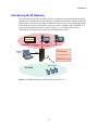
Introducing the IP Gateway ................................................................................................................................... 1-2
IP Gateway Applications ....................................................................................................................................... 1-3
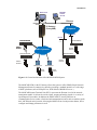
MOSCAD NFM Overview .................................................................................................................................... 1-4
IP Gateway System Overview ............................................................................................................. 2-1
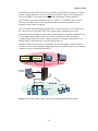
SCADA System ..................................................................................................................................................... 2-1
MDLC Over IP..................................................................................................................................................2-4
MDLC via Terminal Server...............................................................................................................................2-4
MDLC via Astro IP ...........................................................................................................................................2-5
MDLC Over Private DataTac............................................................................................................................2-6
SCADA Interface ..............................................................................................................................................2-7
MOSCAD NFM System ...................................................................................................................................... 2-10
MOSCAD RTU ................................................................................................................................................... 2-12
MOSCAD Toolbox.............................................................................................................................................. 2-12
IP Gateway for TCP/IP........................................................................................................................................ 2-13
IP Gateway Toolbox ............................................................................................................................................ 2-14
IP Gateway Web Server....................................................................................................................................... 2-14
IP Gateway Redundancy...................................................................................................................................... 2-15
HealthCheck Mechanism ..................................................................................................................................... 2-15
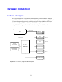
Hardware Installation.......................................................................................................................... 3-1
Hardware description............................................................................................................................................. 3-1
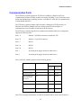
Communication Ports ............................................................................................................................................ 3-2
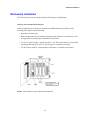
Mechanical Installation.......................................................................................................................................... 3-4
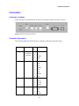
Connectors ............................................................................................................................................................. 3-6
Connector Locations.......................................................................................................................................... 3-6
Connector Description....................................................................................................................................... 3-6
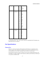
Port Specifications................................................................................................................................................. 3-7
Ethernet Port...................................................................................................................................................... 3-7
IP Gateway Toolbox Port.................................................................................................................................. 3-8
RS-232/RS-485 Communication Ports.............................................................................................................. 3-8
Power Supply......................................................................................................................................................... 3-9
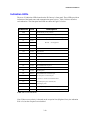
Indication LEDs................................................................................................................................................... 3-10
LEDs Combinations............................................................................................................................................. 3-11
Software Installation ............................................................................................................................ 4-1
Introduction ........................................................................................................................................................... 4-1
IP Gateway Toolbox - Functions and Features ...................................................................................................... 4-2
Prerequisites .......................................................................................................................................................... 4-2
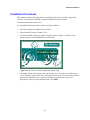
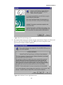
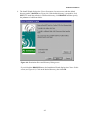
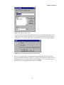
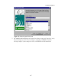
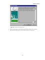
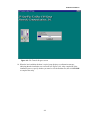
Installation Procedures........................................................................................................................................... 4-3
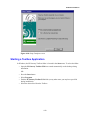
Starting a Toolbox Application............................................................................................................................ 4-10
Entering the Password ......................................................................................................................................... 4-11
Changing the Session Password........................................................................................................................... 4-11
i
March 2003
Contents
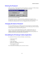
Uninstalling the IP Gateway Toolbox Application .............................................................................................. 4-11
IP Gateway Toolbox ............................................................................................................................. 5-1
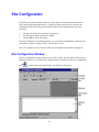
General Concept .................................................................................................................................................... 5-1
Site Configuration ................................................................................................................................ 5-2
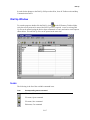
Site Configuration Window ................................................................................................................................... 5-2
ToolBar ............................................................................................................................................................. 5-3
SiteIDBar .......................................................................................................................................................... 5-3
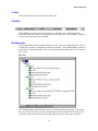
WorkSpaceBar .................................................................................................................................................. 5-3
OutPutBar.......................................................................................................................................................... 5-6
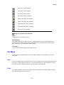
Icons ...................................................................................................................................................................... 5-7
File Menu............................................................................................................................................................... 5-8
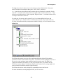
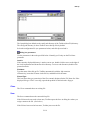
New ................................................................................................................................................................... 5-8
Open .................................................................................................................................................................. 5-9
Save WorkSpace ............................................................................................................................................. 5-10
Save as............................................................................................................................................................. 5-10
Close WorkSpace ............................................................................................................................................ 5-11
Download ........................................................................................................................................................ 5-11
Upload............................................................................................................................................................. 5-13
Abort Upload/Download ................................................................................................................................. 5-14
View Last Upload Information........................................................................................................................ 5-14
Preview Current File ....................................................................................................................................... 5-15
Print................................................................................................................................................................. 5-15
Print Setup....................................................................................................................................................... 5-15
Recent Workspaces ......................................................................................................................................... 5-15
Exit .................................................................................................................................................................. 5-15
CPU Menu ........................................................................................................................................................... 5-16
View Menu .......................................................................................................................................................... 5-16
ToolBar ........................................................................................................................................................... 5-16
WorkSpaceBar ................................................................................................................................................ 5-16
OutPutBar........................................................................................................................................................ 5-16
StatusBar ......................................................................................................................................................... 5-16
SiteIDBar ........................................................................................................................................................ 5-16
Tools Menu.......................................................................................................................................................... 5-16
Options ............................................................................................................................................................ 5-16
Window Menu ..................................................................................................................................................... 5-17
Close................................................................................................................................................................ 5-17
Close All.......................................................................................................................................................... 5-17
Cascade ........................................................................................................................................................... 5-17
Tile Vertically ................................................................................................................................................. 5-18
Tile Horizontally ............................................................................................................................................. 5-18
Help Menu ........................................................................................................................................................... 5-18
Help Topics ..................................................................................................................................................... 5-18
About Site Configuration ................................................................................................................................ 5-18
Port Parameters.................................................................................................................................................... 5-18
Port 2 ............................................................................................................................................................... 5-18
Port 3 ............................................................................................................................................................... 5-21
Port 4 ............................................................................................................................................................... 5-26
IP Port ............................................................................................................................................................. 5-27
ii
Contents
Terminal Server............................................................................................................................................... 5-32
Advanced Parameters .......................................................................................................................................... 5-39
Physical layer .................................................................................................................................................. 5-39
Link Layer ....................................................................................................................................................... 5-43
Transport Multiplex Layer .............................................................................................................................. 5-45
Message-Oriented Service (Frame Sequence) ................................................................................................. 5-45
MDLC Network Layer .................................................................................................................................... 5-46
MDLC Session Logical Channels ................................................................................................................... 5-47
MDLC Mini-session Applications................................................................................................................... 5-48
MDLC and User Port Heaps ........................................................................................................................... 5-50
General System Parameters ............................................................................................................................. 5-51
System Parameters........................................................................................................................................... 5-56
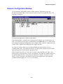
Network Configuration ...................................................................................................................... 5-58
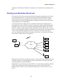
Routing of Data Frames ....................................................................................................................................... 5-58
Routing over Alternative Direct Link .................................................................................................................. 5-59
Network Configuration Window.......................................................................................................................... 5-59
Icons .................................................................................................................................................................... 5-61
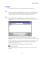
File Menu............................................................................................................................................................. 5-62
New ................................................................................................................................................................. 5-62
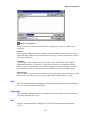
Open ................................................................................................................................................................ 5-62
Close................................................................................................................................................................ 5-63
Save................................................................................................................................................................. 5-63
Save As............................................................................................................................................................ 5-63
Print................................................................................................................................................................. 5-64
Page Setup....................................................................................................................................................... 5-64
Exit .................................................................................................................................................................. 5-64
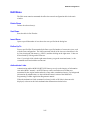
Edit Menu ............................................................................................................................................................ 5-65
Delete Rows .................................................................................................................................................... 5-65
Sort Rows ........................................................................................................................................................ 5-65
Insert Rows...................................................................................................................................................... 5-65
Define Up To................................................................................................................................................... 5-65
Authenticate Links........................................................................................................................................... 5-65
Authentication Options.................................................................................................................................... 5-68
Edit Links Costs .............................................................................................................................................. 5-69
Tools Menu.......................................................................................................................................................... 5-69
View As Text .................................................................................................................................................. 5-69
Download ........................................................................................................................................................ 5-70
Font ................................................................................................................................................................. 5-71
View Menu .......................................................................................................................................................... 5-71
Toolbar ............................................................................................................................................................ 5-71
Status bar......................................................................................................................................................... 5-71
Download window........................................................................................................................................... 5-71
Window Menu ..................................................................................................................................................... 5-71
Cascade ........................................................................................................................................................... 5-72
Tile .................................................................................................................................................................. 5-72
Arrange Icons .................................................................................................................................................. 5-72
Help Menu ........................................................................................................................................................... 5-72
Contents........................................................................................................................................................... 5-72
How to Use Help ............................................................................................................................................. 5-72
iii
Contents
About............................................................................................................................................................... 5-72
MDLC Links Configurator................................................................................................................ 5-73
The MDLC Links Configurator Window............................................................................................................. 5-73
Icons .................................................................................................................................................................... 5-75
File Menu............................................................................................................................................................. 5-76
New ................................................................................................................................................................. 5-76
Open ................................................................................................................................................................ 5-76
Close................................................................................................................................................................ 5-76
Save................................................................................................................................................................. 5-76
Save As............................................................................................................................................................ 5-77
Save All........................................................................................................................................................... 5-77
Print................................................................................................................................................................. 5-77
Activate ........................................................................................................................................................... 5-78
Activate Default .............................................................................................................................................. 5-78
Exit .................................................................................................................................................................. 5-78
Help Menu ........................................................................................................................................................... 5-78
Contents........................................................................................................................................................... 5-78
About............................................................................................................................................................... 5-78
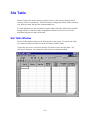
Site Table ............................................................................................................................................. 5-79
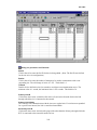
Site Table Window .............................................................................................................................................. 5-79
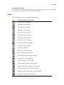
Icons .................................................................................................................................................................... 5-82
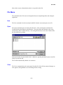
File Menu............................................................................................................................................................. 5-83
New ................................................................................................................................................................. 5-83
Open ................................................................................................................................................................ 5-83
Close................................................................................................................................................................ 5-83
Save................................................................................................................................................................. 5-84
Save As............................................................................................................................................................ 5-84
Print................................................................................................................................................................. 5-84
Download ........................................................................................................................................................ 5-84
Abort ............................................................................................................................................................... 5-85
Exit .................................................................................................................................................................. 5-85
Edit Menu ............................................................................................................................................................ 5-85
Cut................................................................................................................................................................... 5-85
Copy ................................................................................................................................................................ 5-85
Paste ................................................................................................................................................................ 5-85
Insert Site ........................................................................................................................................................ 5-85
Insert Group of Sites ....................................................................................................................................... 5-85
Delete Site ....................................................................................................................................................... 5-87
Delete Group of Sites ...................................................................................................................................... 5-87
Change Retries Value ...................................................................................................................................... 5-87
Change Timeout Value.................................................................................................................................... 5-88
Change Primary Link ID Value....................................................................................................................... 5-88
Change Primary Link Validity Value .............................................................................................................. 5-89
Change Secondary Link ID Value................................................................................................................... 5-89
Change Secondary Link Validity Value .......................................................................................................... 5-90
Sort By Site ID ................................................................................................................................................ 5-90
Default Center ................................................................................................................................................. 5-90
iv
Contents
View Menu .......................................................................................................................................................... 5-91
Toolbar ............................................................................................................................................................ 5-91
Table bar ......................................................................................................................................................... 5-91
Site bar ............................................................................................................................................................ 5-91
Status bar......................................................................................................................................................... 5-91
Window Menu ..................................................................................................................................................... 5-91
Cascade ........................................................................................................................................................... 5-91
Tile .................................................................................................................................................................. 5-91
Arrange Icons .................................................................................................................................................. 5-92
Help Menu ........................................................................................................................................................... 5-92
Contents........................................................................................................................................................... 5-92
How to Use Help......................................................................................................................................... 5-92
About .......................................................................................................................................................... 5-92
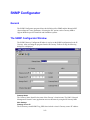
SNMP Configurator ........................................................................................................................... 5-93
General ................................................................................................................................................................ 5-93
The SNMP Configurator Window....................................................................................................................... 5-93
Icons .................................................................................................................................................................... 5-94
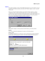
File Menu............................................................................................................................................................. 5-95
New ................................................................................................................................................................. 5-95
Open ................................................................................................................................................................ 5-95
Save................................................................................................................................................................. 5-95
Save As............................................................................................................................................................ 5-95
Download ........................................................................................................................................................ 5-95
Upload............................................................................................................................................................. 5-98
Exit .................................................................................................................................................................. 5-99
Help Menu ........................................................................................................................................................... 5-99
Contents........................................................................................................................................................... 5-99
Using Help ...................................................................................................................................................... 5-99
About ….......................................................................................................................................................... 5-99
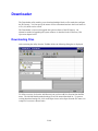
Downloader ....................................................................................................................................... 5-100
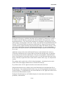
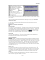
Downloading Files............................................................................................................................................. 5-100
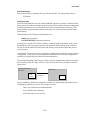
Downloading system software ........................................................................................................................... 5-105
Erasing Configuration ................................................................................................................................... 5-107
Icons .................................................................................................................................................................. 5-107
File Menu........................................................................................................................................................... 5-108
New ............................................................................................................................................................... 5-108
Open .............................................................................................................................................................. 5-109
Save............................................................................................................................................................... 5-110
Save As.......................................................................................................................................................... 5-110
Close.............................................................................................................................................................. 5-111
Open System File .......................................................................................................................................... 5-111
Download ...................................................................................................................................................... 5-112
Abort ............................................................................................................................................................. 5-112
Print............................................................................................................................................................... 5-112
Print Setup..................................................................................................................................................... 5-112
Recent System Files ...................................................................................................................................... 5-112
Recent Download Files.................................................................................................................................. 5-112
Exit ................................................................................................................................................................ 5-112
v
Contents
Edit Menu .......................................................................................................................................................... 5-113
Download This session.................................................................................................................................. 5-113
Rename Session............................................................................................................................................. 5-113
Add Session................................................................................................................................................... 5-113
Copy Session ................................................................................................................................................. 5-113
Paste Session ................................................................................................................................................. 5-113
Cut Session.................................................................................................................................................... 5-113
Delete ............................................................................................................................................................ 5-113
View Menu ........................................................................................................................................................ 5-113
Toolbar .......................................................................................................................................................... 5-114
Status bar....................................................................................................................................................... 5-114
Directory bar ................................................................................................................................................. 5-114
Download bar ................................................................................................................................................ 5-114
Help Menu ......................................................................................................................................................... 5-114
Contents......................................................................................................................................................... 5-114
How to Use Help ........................................................................................................................................... 5-114
About............................................................................................................................................................. 5-114
Dial Up ............................................................................................................................................... 5-115
Modem Connections .......................................................................................................................................... 5-115
Parameter Settings ............................................................................................................................................. 5-116
Dial Up Window................................................................................................................................................ 5-117
Icons .................................................................................................................................................................. 5-117
File Menu........................................................................................................................................................... 5-118
New ............................................................................................................................................................... 5-118
Open .............................................................................................................................................................. 5-118
Close.............................................................................................................................................................. 5-119
Save............................................................................................................................................................... 5-119
Save As.......................................................................................................................................................... 5-120
Print............................................................................................................................................................... 5-120
Merge ............................................................................................................................................................ 5-121
Exit ................................................................................................................................................................ 5-121
Edit Menu .......................................................................................................................................................... 5-122
Cut................................................................................................................................................................. 5-122
Copy .............................................................................................................................................................. 5-122
Paste .............................................................................................................................................................. 5-122
Insert Row ..................................................................................................................................................... 5-122
Delete Current Row....................................................................................................................................... 5-122
Sort ................................................................................................................................................................ 5-122
View Menu ........................................................................................................................................................ 5-122
Toolbar .......................................................................................................................................................... 5-122
Status bar....................................................................................................................................................... 5-122
Phone Menu....................................................................................................................................................... 5-122
Dial Up .......................................................................................................................................................... 5-123
Hang Up ........................................................................................................................................................ 5-123
Window Menu ................................................................................................................................................... 5-123
Cascade ......................................................................................................................................................... 5-123
Tile ................................................................................................................................................................ 5-123
Arrange Icons ................................................................................................................................................ 5-123
Help Menu ......................................................................................................................................................... 5-123
vi
Contents
Contents......................................................................................................................................................... 5-123
How to Use Help ........................................................................................................................................... 5-123
About Dial Up ............................................................................................................................................... 5-123
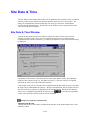
Site Date & Time .............................................................................................................................. 5-124
Site Date & Time Window ................................................................................................................................ 5-124
Icons .................................................................................................................................................................. 5-125
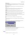
Site Menu........................................................................................................................................................... 5-126
New ............................................................................................................................................................... 5-126
Close.............................................................................................................................................................. 5-126
Exit ................................................................................................................................................................ 5-126
Actions Menu..................................................................................................................................................... 5-126
Get................................................................................................................................................................. 5-126
Set.................................................................................................................................................................. 5-126
Sync............................................................................................................................................................... 5-126
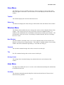
View Menu ........................................................................................................................................................ 5-127
Toolbar .......................................................................................................................................................... 5-127
Status bar....................................................................................................................................................... 5-127
Window Menu ................................................................................................................................................... 5-127
New Window................................................................................................................................................. 5-127
Cascade ......................................................................................................................................................... 5-127
Tile ................................................................................................................................................................ 5-127
Arrange Icons ................................................................................................................................................ 5-127
Help Menu ......................................................................................................................................................... 5-127
Contents......................................................................................................................................................... 5-127
How to Use Help ........................................................................................................................................... 5-128
About Site Date ............................................................................................................................................. 5-128
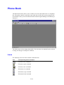
Phone Book........................................................................................................................................ 5-129
Icons .................................................................................................................................................................. 5-129
File Menu........................................................................................................................................................... 5-130
New ............................................................................................................................................................... 5-130
Open .............................................................................................................................................................. 5-131
Close.............................................................................................................................................................. 5-132
Save............................................................................................................................................................... 5-132
Save As.......................................................................................................................................................... 5-132
Print............................................................................................................................................................... 5-133
Merge ............................................................................................................................................................ 5-133
Download ...................................................................................................................................................... 5-134
Exit ................................................................................................................................................................ 5-134
Edit Menu .......................................................................................................................................................... 5-134
Cut................................................................................................................................................................. 5-134
Copy .............................................................................................................................................................. 5-134
Paste .............................................................................................................................................................. 5-134
Insert Row ..................................................................................................................................................... 5-134
Delete Row.................................................................................................................................................... 5-134
Sort Table...................................................................................................................................................... 5-134
View Menu ........................................................................................................................................................ 5-134
Toolbar .......................................................................................................................................................... 5-134
Status bar....................................................................................................................................................... 5-135
vii
Contents
Window Menu ................................................................................................................................................... 5-135
Cascade ......................................................................................................................................................... 5-135
Tile ................................................................................................................................................................ 5-135
Arrange Icons ................................................................................................................................................ 5-135
Help Menu ......................................................................................................................................................... 5-135
Contents......................................................................................................................................................... 5-135
How to Use Help ........................................................................................................................................... 5-135
About............................................................................................................................................................. 5-135
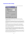
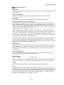
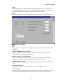
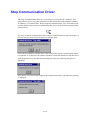
Communication Setup...................................................................................................................... 5-136
Stop Communication Driver ........................................................................................................... 5-139
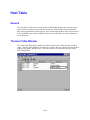
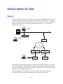
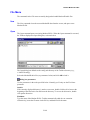
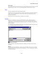
Host Table ......................................................................................................................................... 5-140
General .............................................................................................................................................................. 5-140
The Host Table Window.................................................................................................................................... 5-140
Icons .................................................................................................................................................................. 5-141
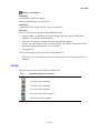
File Menu........................................................................................................................................................... 5-142
New ............................................................................................................................................................... 5-142
Open .............................................................................................................................................................. 5-142
Save............................................................................................................................................................... 5-143
Save As.......................................................................................................................................................... 5-143
Close.............................................................................................................................................................. 5-144
Print............................................................................................................................................................... 5-144
Exit ................................................................................................................................................................ 5-144
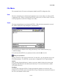
Edit Menu .......................................................................................................................................................... 5-144
New Host....................................................................................................................................................... 5-144
Delete Host.................................................................................................................................................... 5-144
Copy Host...................................................................................................................................................... 5-144
Paste Host...................................................................................................................................................... 5-144
Action Menu ...................................................................................................................................................... 5-145
Upload........................................................................................................................................................... 5-145
Download ...................................................................................................................................................... 5-145
Help Menu ......................................................................................................................................................... 5-145
Help Topics ................................................................................................................................................... 5-145
About............................................................................................................................................................. 5-145
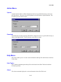
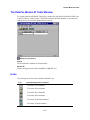
DataTac Modem ID Table ............................................................................................................... 5-146
General .............................................................................................................................................................. 5-146
The DataTac Modem ID Table Window ........................................................................................................... 5-147
Icons .................................................................................................................................................................. 5-147
File Menu........................................................................................................................................................... 5-148
New ............................................................................................................................................................... 5-148
Open .............................................................................................................................................................. 5-148
Save............................................................................................................................................................... 5-149
Save As.......................................................................................................................................................... 5-149
Close.............................................................................................................................................................. 5-150
Print............................................................................................................................................................... 5-150
Exit ................................................................................................................................................................ 5-150
viii
Contents
Edit Menu .......................................................................................................................................................... 5-150
New ............................................................................................................................................................... 5-150
Delete ............................................................................................................................................................ 5-150
Action Menu ...................................................................................................................................................... 5-151
Upload........................................................................................................................................................... 5-151
Download ...................................................................................................................................................... 5-151
Help Menu ......................................................................................................................................................... 5-151
Help Topics ................................................................................................................................................... 5-151
About............................................................................................................................................................. 5-151
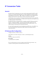
IP Conversion Table......................................................................................................................... 5-152
General .............................................................................................................................................................. 5-152
IP Gateway Site Configuration .......................................................................................................................... 5-152
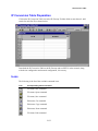
IP Conversion Table Preparation....................................................................................................................... 5-153
Icons .................................................................................................................................................................. 5-153
File Menu........................................................................................................................................................... 5-154
New ............................................................................................................................................................... 5-154
Open .............................................................................................................................................................. 5-155
Close.............................................................................................................................................................. 5-155
Save............................................................................................................................................................... 5-155
Save As.......................................................................................................................................................... 5-155
Print............................................................................................................................................................... 5-156
Download ...................................................................................................................................................... 5-156
Upload........................................................................................................................................................... 5-156
Abort ............................................................................................................................................................. 5-156
Exit ................................................................................................................................................................ 5-156
Edit Menu .......................................................................................................................................................... 5-156
Cut................................................................................................................................................................. 5-156
Copy .............................................................................................................................................................. 5-156
Paste .............................................................................................................................................................. 5-156
View Menu ........................................................................................................................................................ 5-157
Toolbar .......................................................................................................................................................... 5-157
Tablebar ........................................................................................................................................................ 5-157
Sitebar ........................................................................................................................................................... 5-157
Statusbar........................................................................................................................................................ 5-157
Window Menu ................................................................................................................................................... 5-157
Cascade ......................................................................................................................................................... 5-157
Tile ................................................................................................................................................................ 5-157
Arrange Icons ................................................................................................................................................ 5-157
Help Menu ......................................................................................................................................................... 5-158
About IP Conv. Table.................................................................................................................................... 5-158
SW Diagnostics & Loggers .............................................................................................................. 5-159
SW Diagnostics and Loggers Window .............................................................................................................. 5-159
Error Logger Tool.............................................................................................................................................. 5-160
Software Diagnostics Tool................................................................................................................................. 5-161
Icons .................................................................................................................................................................. 5-162
File Menu........................................................................................................................................................... 5-162
New ............................................................................................................................................................... 5-163
Open for Editing............................................................................................................................................ 5-163
ix
Contents
Save As.......................................................................................................................................................... 5-164
Select Central File ......................................................................................................................................... 5-165
Close Central File.......................................................................................................................................... 5-165
Print............................................................................................................................................................... 5-165
Print Setup..................................................................................................................................................... 5-165
Recent Error Logger Files ............................................................................................................................. 5-165
Recent Diagnostics Files ............................................................................................................................... 5-165
Edit Menu .......................................................................................................................................................... 5-166
Undo.............................................................................................................................................................. 5-166
Cut................................................................................................................................................................. 5-166
Copy .............................................................................................................................................................. 5-166
Paste .............................................................................................................................................................. 5-166
Delete ............................................................................................................................................................ 5-166
Find ............................................................................................................................................................... 5-166
Replace.......................................................................................................................................................... 5-166
Clear View..................................................................................................................................................... 5-166
Loggers Menu.................................................................................................................................................... 5-166
Error Logger.................................................................................................................................................. 5-166
Diagnostics .................................................................................................................................................... 5-167
Start ............................................................................................................................................................... 5-176
Device List .................................................................................................................................................... 5-176
Abort ............................................................................................................................................................. 5-177
View Menu ........................................................................................................................................................ 5-177
Toolbar .......................................................................................................................................................... 5-177
Status bar....................................................................................................................................................... 5-177
Site bar .......................................................................................................................................................... 5-177
Loggers Bar ................................................................................................................................................... 5-177
Device Bar..................................................................................................................................................... 5-178
Window Menu ................................................................................................................................................... 5-178
Cascade ......................................................................................................................................................... 5-178
Tile ................................................................................................................................................................ 5-178
Arrange Icons ................................................................................................................................................ 5-178
Fonts.............................................................................................................................................................. 5-178
Help Menu ......................................................................................................................................................... 5-178
Contents......................................................................................................................................................... 5-178
How to Use Help ........................................................................................................................................... 5-178
About............................................................................................................................................................. 5-178
Advanced Features ............................................................................................................................... 6-1
HealthCheck Mechanism ..................................................................................................................... 6-2
General .................................................................................................................................................................. 6-2
MDLC Infrastructure ............................................................................................................................................. 6-2
Mechanism............................................................................................................................................................. 6-2
Disabled HealthCheck....................................................................................................................................... 6-3
HealthCheck Setup ................................................................................................................................................ 6-3
Setting up the Site Table ................................................................................................................................... 6-3
Site Configuration ............................................................................................................................................. 6-4
HealthCheck Diagnostics....................................................................................................................................... 6-4
x
Contents
Adding Terminal Server Ports ............................................................................................................ 6-6
General .................................................................................................................................................................. 6-6
Site Configuration for Terminal Server ................................................................................................................. 6-7
Configuring Terminal Server to work with IP Gateway ........................................................................................ 6-8
Configuration .................................................................................................................................................... 6-8
Wiring ............................................................................................................................................................... 6-9
Example: EQUINOX ELS16 Terminal Server Wiring and Configuration ............................................................ 6-9
General .............................................................................................................................................................. 6-9
Wiring ............................................................................................................................................................... 6-9
Configuration .................................................................................................................................................. 6-10
Example: Setting 14 Ports (port 3 to 16) of ELS16 to the IP Gateway: .......................................................... 6-12
IP Gateway Redundancy ................................................................................................................... 6-16
Redundant IP Gateway Configurations................................................................................................................ 6-16
Site Configuration................................................................................................................................................ 6-17
IP Gateway Web Operation .............................................................................................................. 6-18
General ................................................................................................................................................................ 6-18
Site Map .......................................................................................................................................................... 6-18
Security ........................................................................................................................................................... 6-19
Accessing the Web Server ................................................................................................................................... 6-20
The Tools............................................................................................................................................................. 6-22
Downloading System Software using the Web Server .................................................................................... 6-22
Retrieving Errors using the Web Server.......................................................................................................... 6-23
Retrieving Software Diagnostics using the Web Server .................................................................................. 6-24
Setting SNMP Configuration using the Web Server ....................................................................................... 6-25
Sending Email to the Web Server Administrator ............................................................................................ 6-26
IP Gateway Telnet Application ......................................................................................................... 6-27
General ................................................................................................................................................................ 6-27
Telnet User Interface ........................................................................................................................................... 6-27
Connecting to the IP Gateway ......................................................................................................................... 6-27
Telnet Command Summary............................................................................................................................. 6-28
Example Output............................................................................................................................................... 6-31
APPENDIX A: RS232 Adapter Cables ............................................................................................ A-1
Connection to a Computer or Terminal ................................................................................................................ A-1
Connection to a Modem........................................................................................................................................ A-2
Connection to a Radio .......................................................................................................................................... A-2
RTU-to-RTU Connection Using MDLC Protocol through RS232....................................................................... A-4
RTU-to-RTU Synchronous Communication Using Port 3, 4............................................................................... A-5
APPENDIX B: Remote ToolBox Modem Setup ...............................................................................B-1
Hayes ACCURA 144 + FAX 144......................................................................................................................... B-1
Motorola OnlineSURFR 28.8 ............................................................................................................................... B-4
Motorola OnlineSURFR 33.6 ............................................................................................................................... B-7
Motorola OnlineSURFR 56K ............................................................................................................................... B-8
UDS V.3225 ......................................................................................................................................................... B-9
xi
Contents
USRobotics Sportster 14400 Fax........................................................................................................................ B-12
USRobotics Sportster 28800 Fax........................................................................................................................ B-15
USRobotics Sportster 56K Fax........................................................................................................................... B-18
Intel SatisFAXtion Modem/400e........................................................................................................................ B-19
Software Diagnostics Output.............................................................................................................. C-1
TRANSPORT MUX DEVICE = TRNINT ........................................................................................................ C-1
HEAP DEVICE = HP_F_TX, HP_F_RX, HP_UF_A, HP_UF_U.................................................................... C-3
ADAPTER DEVICE = COM1A,RTU1A, LIN1A,… ....................................................................................... C-5
TRANSPORT DEVICE = TRANS1, TRANS2,... ............................................................................................ C-6
MTE...................................................................................................................................................................... C-9
LINK................................................................................................................................................................... C-10
NETWORK STOCK (NSTOCK).................................................................................................................... C-13
NETWORK (NETWRK) .................................................................................................................................. C-14
MINISESSION (EVNT , STCL) ..................................................................................................................... C-15
HDLC (RAD1P, RAD2P,...)............................................................................................................................. C-19
UART ................................................................................................................................................................. C-26
RADIO CHANNEL (RAD1C , RAD2C,…) ...................................................................................................... C-38
TRUNK CHANNEL .......................................................................................................................................... C-42
RS232 CHANNEL ............................................................................................................................................. C-46
MODEM CHANNEL ......................................................................................................................................... C-50
TIMERS (10__MS , 100_MS , 1__SEC , 1__MIN) ........................................................................................ C-55
RS485 ................................................................................................................................................................. C-55
FLASH MEMORY (FLASHDB, FLSEXT1).................................................................................................... C-59
LDIALER (DIL2D , DIL 3D)........................................................................................................................... C-61
(ML_DL) ............................................................................................................................................................ C-62
TOPLC (PLC1L, PLC2L, PLC3L)..................................................................................................................... C-63
FRAME - SEQ.................................................................................................................................................... C-64
BURST - SEQ .................................................................................................................................................... C-65
PHONE BOOK LEVEL = 0 PHNBK ............................................................................................................ C-65
TIMER EVENT.................................................................................................................................................. C-66
STBLA (SITE TABLE)...................................................................................................................................... C-67
POOLMNGR...................................................................................................................................................... C-67
OCOMM LEVEL = 0...................................................................................................................................... C-69
FSKADP (OCOMC)........................................................................................................................................... C-73
GPS..................................................................................................................................................................... C-79
TCP/IP ................................................................................................................................................................ C-82
GAUART DEVICE = COMxA, RTUxA, LINxA........................................................................................... C-84
SITTBL .............................................................................................................................................................. C-87
IPLINK
LINxL .............................................................................................................................................. C-88
SLIP
LINxSlp ................................................................................................................................................ C-93
IPLINK
LINxL ............................................................................................................................................ C-101
DMAP27 DEVICE = RADxD........................................................................................................................ C-113
MPT1327 (PHYSICAL MODULE) DEVICE = RADxP.............................................................................. C-115
IMAP27 ............................................................................................................................................................ C-122
DESx................................................................................................................................................................. C-125
AUSYNC.......................................................................................................................................................... C-126
TMAUTH ......................................................................................................................................................... C-128
REQMNG......................................................................................................................................................... C-129
HELTHCH (HEALTH CHECK)...................................................................................................................... C-131
xii
Contents
LNKHNDL....................................................................................................................................................... C-131
DOCTOR.......................................................................................................................................................... C-132
Error Messages ................................................................................................................................ C-133
Error Logger Messages..................................................................................................................................... C-133
xiii
Introduction
Scope of the Manual
This manual provides instructions for IP Gateway installation and operation, as well as
detailed instructions for the setup of its configuration. In addition, this manual provides the
user with an overview of the MOSCAD system including a few examples that show SCADA
control centers and NFM Manager which are integrated into the MOSCAD system via the IP
Gateway.
Additional applicable manuals are:
•
MOSCAD Programming Toolbox, System Overview Manual, 68P02956C45
•
MOSCAD Programming Toolbox, System Setup and Diagnostics Tools Manual,
68P02956C50
•
MOSCAD Programming Toolbox, Application Programmer Manual, 68P02956C55
•
MDLC Gateway for TCP/IP Application Programming Interface – User’s Manual,
68P02951C05
•
MOSCAD NFM Manual, 68P02958C45
•
MOSCAD RTU Service Manual, 68P02991G90
IP Gateway System and ToolBox Software Version Policy
The version numbers of the ToolBox and system software are updated according to additional
features and improvements.
Compatibility (at source level) between the ToolBox and the IP Gateway is assured only if the
version number of the ToolBox Software is later than the version number of the Gateway
system software.
A version number is composed of two numbers, as in the following example: V1.61. The onedigit number to the left of the decimal point describes a major modification of the software,
while the two-digit number to the right of the decimal point describes a minor modification.
In this manual, some headings of major subjects are marked by the following annotation:
≥ Va.b.
For example, ≥ V1.61 indicates that the marked subject is supported by a Gateway whose
system software version number is at least 1.61.
1-1
Introduction
Introducing the IP Gateway
The IP Gateway for SCADA and NFM systems is a smart unit, based on the Motorola 68360
microprocessor and includes on-board memory, communication channels, indicator LEDs and
other circuits. It provides the SCADA and NFM software with access to the MOSCAD system,
based on the seven layers of the MDLC protocol, in order to exchange data with the RTUs. A
typical example of the IP Gateway is shown in Figure 1-1; a SCADA control center is
connected via the IP Gateway to a radio link of the MOSCAD system.
SCADA
Computer
Work Stations
TCP/IP on Ethernet
MOSCAD
ToolBox
IP Gateway
RS232
Your gateway into the
MOSCAD world
MDLC on Radio
MOSCAD
RTU
RTU
RTU
Figure 1-1: MOSCAD System with IP Gateway, General View
1-2
Introduction
A system with multiple vendors SCADA control center is shown in Figure 1-2. The MDLC
communicates with any SCADA computer which supports the TCP/IP network (UNIX, VMS,
Windows/NT, Windows/95, OS/2 etc.).
NFM Central
MOSCAD
ToolBox
(over IP)
Ethernet
TCP/IP
IP Gateway
IP Network
MDLC over IP
Ethernet
MDLC over RS485
MDLC over Radio
RTU
RTU
RTU
RTU
Figure 1-2: IP Gateway with Multiple Vendors SCADA Control Center
The SCADA control center, which includes workstations and a SCADA computer, exchanges
data with the MOSCAD system via the IP Gateway, which serves as a Gateway from the
TCP/IP world to the MDLC world. There are many SCADA packages which already have the
Gateway Interface driver implemented, some as direct access to the IP Gateway, and some as
OPC server.
IP Gateway Applications
The IP Gateway uses the TCP/IP LAN Protocol for exchanging data application messages with
the SCADA software. The IP Gateway API (Application Programming Interface) source
library allows SCADA developers to quickly and easily connect to the MOSCAD world. The
IP Gateway API, which is part of the IP Gateway product line, allows SCADA driver
developers to quickly and easily build the IP Gateway Interface (driver), which serves as a
communication interface with the MOSCAD world.
Data exchange between the SCADA (client) and the IP Gateway (server) is carried out using
"peer -to-peer" communication over the LAN. The IP Gateway can support multiple
connections that are initiated from multiple SCADA computers.
The implementation of the IP Gateway interface in the SCADA software allows the SCADA
to perform the following:
•
Poll a MOSCAD RTU in order to get data and COS (Change-of-State) events from the
RTU tables.
1-3
Introduction
•
Send commands to the MOSCAD RTU and download parameters to its local process.
•
Send commands via broadcasts to any required group of RTUs.
•
Download parameters (set-points) to the RTU local process.
•
Receive spontaneous reports (by contention) from RTUs (both burst and event
transmission).
•
Receive time-tagged events logged in the RTUs (1 msec resolution).
•
Adjust the RTU clocks (1 sec resolution).
•
Synchronize the RTU clocks (1 msec resolution), using an external CPU with GPS.
•
Support redundant IP Gateway configuration.
•
Set the Gateway mode (Primary/Secondary).
•
Retrieve Gateway status.
•
Retrieve RTU links status.
MOSCAD NFM Overview
The MOSCAD NFM system provides communication providers with a solution for
supervising and controlling the operation of conventional and trunked radio, analog and digital
cellular, microwave radio and wireline telecommunication systems.
The MOSCAD NFM system provides the Network Management Center (NMC) with access to
the communication and environmental devices and gives the operator and the system manager
the tools needed to identify and fix faults within the communication system.
Figure 1-3 describes the general architecture of the MOSCAD NFM, which includes control
center workstations and computers that exchange data with the IP Gateway, allowing the NMC
to monitor and control non-SNMP devices at the communication sites.
1-4
Introduction
NFM Central
MOSCAD
ToolBox
(over IP)
Ethernet
SNMP
TCP/IP
IP Gateway
(Proxy MIB)
IP Network
Ethernet
Ethernet
MOSCAD NFM RTU
MOSCAD NFM RTU
SNMP
Network
Elements
Network
Elements
MDLC Network
MOSCAD NFM RTU
MOSCAD NFM RTU
Network
Elements
Network
Elements
MOSCAD RTU
MOSCAD RTU
Network
Elements
Network
Elements
Figure 1-3: General Architecture of the MOSCAD NFM System
The MOSCAD NFM via the IP Gateway allows the system to offer SNMP (Simple Network
Management Protocol) connectivity, therefore providing a standard interface to a wide range
of NMC platforms (such as HP/OpenView, SUN/Solstice, IBM/NetView etc.).
The MOSCAD Remote Terminal Unit (RTU) represents the Element Level of the network
management model. It collects the various inputs, outputs and analog signals via a variety of
input/output (I/O) modules. In addition, the MOSCAD RTU serially interfaces to
communication devices (radio, cellular and telecommunication) and is able to emulate (speak)
their ASCII based native protocol, allowing the MOSCAD to not only monitor alarms, but to
configure and change parameters as well.
1-5
IP Gateway System Overview
SCADA System
The complete control system is comprised of the SCADA control center (or centers)
communicating with MOSCAD RTUs over various communication links, such as:
•
•
•
•
•
•
conventional radio
trunked radio
data radio, dial-up lines
leased lines,
microwave, fiber optic links
combined networks
The communication system is used for transmitting alarms, status and telemetry, calculated
data diagnostics and error logging information from the MOSCAD RTUs to the central facility
computer and vice versa. It is also used for downloading, monitoring and debugging the
application program at the sites.
The system may be relatively simple, comprising several RTUs and a single control center, or
a more complicated hierarchical system, where several sub-control-centers communicate with
lower, parallel and higher hierarchies. The RTUs may also communicate with each other
and/or with any other hierarchy in the system.
The MOSCAD system uses the MDLC protocol, based on the seven layers of the OSI model
published by ISO, and adapted for SCADA communications. It provides network support,
multiple logical channels per physical port, allowing each RTU to simultaneously run several
communication sessions, such as data exchange, on-line monitoring, diagnostics, etc.
The MOSCAD system is supplied with a Toolbox, which is a software package that runs on an
IBM PC (or compatible). All RTU functions such as configuration, database and process
definition, downloading, monitoring, hardware and software diagnostics, etc. are defined by
means of the MOSCAD Programming Toolbox.
Figure 2-1 describes a typical MOSCAD radio system. The IP Gateway includes one Ethernet
port for connection to the SCADA computer and 3 serial ports for communicating via MDLC
protocol to the MOSCAD devices. In this particular case, one MDLC port is connected to the
MOSCAD Programming Toolbox and the second MDLC port is connected to a radio for
communicating with the RTUs.
2-1
System Overview
SCADA
Computer
Work Stations
TCP/IP on Ethernet
MOSCAD
ToolBox
IP Gateway
RS232
Your gateway into the
MOSCAD world
MDLC on Radio
MOSCAD
RTU
RTU
RTU
Figure 2-1: SCADA Control Center with Radio-Based MOSCAD System
2-2
System Overview
The IP Gateway allows the SCADA center to conduct a large number of sessions via a large
number of logical channels in spite of a single physical RS-232 port. The IP Gateway also
serves as an MDLC router between the MOSCAD Programming Toolbox and RTUs.
The Toolbox may be connected either locally to an RTU or via the MDLC port of the IP
Gateway to any RTU in the system. All programming and monitoring functions can be
performed either locally or remotely.
Note: The MOSCAD Programming Toolbox that is connected locally to one of the RTUs in
the system can service any other RTU in the system via the communication network.
Figure 2-2 describes multiple SCADA control centers which are connected to the IP Gateway
via a 10 Mbps Ethernet LAN. In this case, multiple TCP/IP logical links are used for
communicating with the IP Gateway, which is connected via multiple MOSCAD CPUs to
multiple MDLC links (Radio link, Line link, Dial-up link etc.).
Multiple SCADA control centers can simultaneously perform multiple sessions with the IP
Gateway in order to send commands and polling requests to the RTUs and to receive data and
contention reports from the MOSCAD RTUs.
SCADA
Computer
SCADA
Computer
Work Stations
TCP/IP on Ethernet
MOSCAD
ToolBox
RS232
MDLC on RS485
Leased
Line
Wire Line
MOSCAD
MDLC on Radio
Dial up Modem
RTU
RTU
RTU
RTU
RTU
RTU
RTU
RTU
Figure 2-2: SCADA Control Center with Multiple Links-Based MOSCAD System
2-3
System Overview
MDLC Over IP
MOSCAD RTUs and IP Gateways can use IP (Internet Protocol) technology to interface to
advanced radio infrastructure (e.g. digital ASTRO IP conventional systems) and to standard
private IP networks. Most benefits of the MDLC protocol are preserved. MDLC and IP
networks can be integrated in the same system, as networking properties are preserved.
MOSCAD MDLC applications need not be modified as the lower layers of the protocol
support IP.
MDLC packets to be transmitted are enveloped inside IP datagrams and sent between remote
RTUs or between an IP Gateway and an RTU.
An IP Gateway can act as a gateway between the field and the SCADA Central to extract the
enveloped frames from the IP message. A ToolBox can be connected to one of the RTUs or to
the IP Gateway, either locally or over IP network.
Each RTU/IP Gateway is assigned a Site ID. In addition, each RTU/IP Gateway with an IP
interface is assigned an IP address. An IP conversion table which maps Site IDs to IP
addresses is created in the ToolBox and downloaded to the RTUs and IP Gateway. This
enables routing over the IP network to the proper destination.
Two variations of MDLC over IP exist, MDLC via Terminal Server and MDLC via Astro IP.
MDLC via Terminal Server
If the RTUs are on a Local Area Network (LAN), each can be connected to a Terminal Server
attached to the Ethernet. The Terminal Server converts the RS232 to the Ethernet LAN and
enables communication with an IP Gateway, or between RTUs.
In the diagram below, a typical configuration is shown, with RTUs attached via SLIP (Serial
Line IP) port to a Terminal Server, which is in turn attached to Ethernet.
2-4
System Overview
SCADA Central
Ethernet
LINE 1
IP Gateway
ToolBox
(over IP)
IP Gateway
(Proxy MIB)
RS232
IP Network
Ethernet
MDLC Network
Terminal Server
MOSCAD
Programming
ToolBox
(over IP)
LINE 1
LINE 1
Terminal Server
LINE 1
LINE 1
RS232
MOSCAD
RTU IP1
MOSCAD
RTU IP2
MOSCAD
RTU IP3
MOSCAD
RTU IP4
Figure 2-3: Typical Configuration, MDLC via Terminal Server
MDLC via Astro IP
RTUs can be connected via SLIP connection to an ASTRO radio, which is part of an IP
network.
In the diagram below, a typical configuration is shown, with RTUs attached via SLIP over
RS232-E to ASTRO SPECTRA radios which support IP data capability. A ToolBox is
connected to one of the RTUs through either Port 2 or Port 3. The IP Gateway on Ethernet
acts as a gateway, translating between the IP and MDLC protocols.
2-5
System Overview
SCADA Central
Ethernet
IP Cloud
LINE 1
IP Gateway
ToolBox
(over IP)
RS232
IP Gateway
RNC
ASTRO RF
System
MOSCAD
Programming
ToolBox
(over IP)
IP Network
ASTRO Spectra Radio
ASTRO Spectra Radio
LINE 1
SLIP
Connection
LINE 1
SLIP
Connection
RS232
MOSCAD
RTU
MOSCAD-L
RTU
Figure 2-4: Typical Configuration, MDLC via Astro IP
MDLC Over Private DataTac
MOSCAD RTUs can communicate over Private DataTac systems (RDLAP) with SCADA
centrals and with other RTUs. All MDLC features are preserved except for clock
synchronization.
RTUs are connected to RDLAP (DataTac) radios (e.g. VRM 500, 600, 650, 660, and TRM
660) via RS232. An RTU sends a message (MDLC), through the radio to the Radio Network
Controller (RNC). The RNC encapsulates the MDLC message and send it over IP to the IP
Gateway. The IP Gateway then extracts the MDLC message from the IP envelope and
transmits it to the appropriate destination. If the destination is another RTU over Private
DataTac, the IP Gateway must support the reflector feature, which enables it to “reflect” the
message back over RDLAP (DataTac).
2-6
System Overview
SCADA Central
Host
Computer
Ethernet
IP Cloud
LINE 1
RS232
IP Gateway
with
Reflector
IP Gateway
ToolBox
(over IP)
RNC
RF System
Private DataTAC Radio
Private DataTAC Radio
MOSCAD
Programming
ToolBox
(over IP)
RS232
RS232
RS232
MOSCAD
RTU
MOSCAD-L
RTU
Figure 2-5: Typical Configuration, MDLC via Private DataTac radios.
The picture above shows a typical system which supports MDLC communication over RDLAP
(DataTac) radios. Note that the IP Gateway is configured as RDLAP (DataTac) reflector. A
host computer attached to the Ethernet can receive TCP/IP applications from non-MOSCAD
terminals on existing RDLAP (DataTac) systems, if required. A MOSCAD Programming
ToolBox can be connected to one of the RTUs, and can access another RTU by using its Site
ID and Link ID. ToolBox can also be attached to one of the serial ports of the IP Gateway.
SCADA Interface
Client-Server environment
The SCADA application for the IP Gateway is based on a client-server approach.
The IP Gateway application acts as a server while the SCADA Interface acts as a client. In
such a relationship, the SCADA Interface must establish the connections with the IP Gateway
needed for communicating with the MOSCAD RTUs.
After the connections have been established, the SCADA Interface can send data, commands,
and polling requests to the field RTUs. It can also establish a special connection that enables
2-7
System Overview
receipt of data transmissions initiated by the field RTUs (so called burst/RTU event data,
contention data or Change-Of-State [COS] messages).
A specialized routine, API CONNECT, allows the SCADA Interface to establish the most
fitting mode of communication with the IP Gateway, based on the existing SCADA
communication mode.
Channels and Channel types
The SCADA Interface must establish at least one connection toward the IP Gateway server.
These connections are called channels and are used to transfer messages from the SCADA
center toward both the Gateway and the RTUs in the field. The client application can open
different types of channels to best serve its SCADA Interface process.
The two basic channel types are:
•
Regular
•
Spontaneous
A Regular channel enables asynchronous sending/receiving of data and requests. It uses
amailbox mechanism for mapping the request messages to their replies.
A Spontaneous channel allows receiving burst data (Spontaneous COS messages) and RTU
events - i.e. transmissions initiated by the field RTUs. This feature almost eliminates the need
for the SCADA application to poll data since every change in one of the telemetry field
variables can immediately be transmitted to the SCADA application.
MOSCAD System - RTU definitions
To make the MOSCAD field system definition transparent to the SCADA client application
and to correctly parse the data received from the MOSCAD system, the API builds an internal
data structure defining the types and numbers of the field RTUs. To do so, it uses two external
system definition files (in ASCII format).
This automatic system definition done by the API routines hides the field system structure
from the SCADA application and eliminates the need for any application modifications when
working with different MOSCAD systems. Moreover, new RTUs can be added to the system
at run time using the appropriate API routine.
Primary/Secondary Gateway Modes
The IP Gateway supports a redundant configuration. There are two modes of operation:
Primary and Secondary. The initial mode of operation is defined by the startup process of the
IP Gateway. At any other time, the SCADA can change the mode of operation flexibly by
calling the appropriate API set mode routine. The API also supplies a routine for checking the
current mode of operation. This functionality of the IP Gateway provides redundant gateway
operation, which minimizes the risk of communication failure.
2-8
System Overview
Communicating with the IP Gateway
Once a channel has been established with the IP Gateway, the SCADA interface can issue
requests to the IP Gateway. The request categories are Send routines, Receive routines, Data
Analysis routines and Management routines.
Typical API sequence calls are the following:
Connect
/* Establish Connection to Gateway. */
Poll
/* Send a polling request. */
Receive
/* Receive MDLC communication (answer) buffer. */
Get_next_message
/* Extract one message from the MDLC communication buffer. */
Get_next_data_entity /* Get one data entity from the message buffer. */
Troubleshooting
The IP Gateway handles the communication with the SCADA in the REQMNG device.
Diagnostics on this device can help when troubleshooting the SCADA connectivity.
For more information on the REQMNG device, see the Software Diagnostics Output section.
2-9
System Overview
MOSCAD NFM System
A typical network management system can be divided into three main levels:
•
•
•
Network Management Level
Element Manager Level
Element Level
The following section provides a brief description of the MOSCAD NFM components that
allow managing and supporting these network management levels.
Figure 2-6 shows a typical MOSCAD NFM configuration including all network management
levels. It describes the MOSCAD NFM architecture that includes NMC computers and
workstations that monitor and control - via the IP Gateway and the NFM RTUs - non-SNMP
devices at the communication sites.
In this configuration, the end devices at the communication sites serve as a NE (Network
Element) and the NFM RTU serves as an Element Manager that monitors and controls multicommunication and environmental devices at the site. The IP Gateway allows monitoring and
controlling devices - via the NFM RTU - that are installed at multiple communication sites.
The NMC allows monitoring and controlling of all devices in the network via multiple IP
Gateways.
The NMC application can use the SNMP protocol and the IP Gateway MIB to Auto-discover
the IP Gateway, the communication sites as well as the devices and their objects.
By using this MIB, the NMC application can poll the devices and their objects (NEs and their
objects) in order to refresh its database and to display unsolicited events (Traps ) in the Alarm
Manager application. By using the TELNET application in the host, the operator can access
via the IP Gateway and the NM RTU any communication devices that have an RS-232 port
with interactive interface.
The MOSCAD NFM product can be integrated either with the Motorola PRN (Private Radio
Network) architecture or with a third party communication/telecommunication system via an
IP Gateway that gives the NMC applications access to the equipment and environmental
devices at the sites.
2-10
System Overview
Network Management Center
System Support Center
Telnet
Work Station
TCP/IP on Ethernet
MOSCAD
ToolBox
Terminal Server
RS232
1
...
32
Communication Site MDLC
SC
RS485
EMU
...
EMU
EMU
MDLC Network
ENVIRONMENTAL
SENSORS
DEVICE DEVICE
W
X
LEGEND
Device
Application
Site
Concentrator
SC
EMU
Element
Management
Unit
Communication Site MDLC
SC
Communication Site MDLC
SC
RS485
RS485
EMU
...
ENVIRONMENTAL
SENSORS
EMU
EMU
DEVICE DEVICE
Y
Z
EMU
...
ENVIRONMENTAL
SENSORS
EMU
DEVICE DEVICE
Y
Z
Figure 2-6: MOSCAD NFM System Architecture with TELNET Application
2-11
EMU
System Overview
MOSCAD RTU
The MOSCAD RTU is a smart modular unit designed to operate as a stand-alone controller or
as part of a system having any number of RTUs, control centers and sub-centers connected
through a communication network with any number of links and nodes.
The MOSCAD RTU must be configured and loaded with the appropriate application using the
MOSCAD Programming Toolbox.
The MOSCAD RTU is a microprocessor-based unit, which basically consists of a CPU
module and various I/O and communication modules. A wide range of I/O and communication
modules makes the MOSCAD system flexible to meet most application requirements.
For further details on the MOSCAD RTU, refer to the MOSCAD Owner’s Manual and the
MOSCAD Service Manual.
MOSCAD Toolbox
The MOSCAD Programming Toolbox software package allows the system engineer to define
and maintain the MOSCAD system according to user needs and requirements. The following
main functions may be performed by means of the MOSCAD Programming Toolbox:
1.
Editing the RTU user program including the following:
•
Site Configuration according to hardware and port configuration
•
Network Configuration according to network configuration
•
Application database
•
Application process
2.
Preparing project documentation for the user
3.
Automatically creating a central file to be used later during RTU database creation in the
SCADA control center
4.
Downloading Site Configuration to the MOSCAD RTU via the RS-232 port of the unit
5.
Performing the following functions on any MOSCAD RTU either via local connection or
via the communication network:
•
Uploading Site Configuration and related data
•
Downloading Application Program and Network Configuration
•
Real-time symbolic (graphic) monitoring and debugging of the application (both
database and process)
•
Updating time and date at RTU sites
2-12
System Overview
•
Testing all hardware modules, including software calibration of analog inputs and
outputs
•
Retrieving time-tagged events (of down to 1mSec resolution) logged in the RTUs
•
Synchronizing the RTU real-time clock
•
Retrieving errors logged in the RTUs (hardware or software malfunctions)
•
Capturing the data packets on the communication links and analyzing the protocol
seven layer
•
System software diagnostics by object entity names
The definition of the RTU application program allows the system engineer to build the RTU’s
database in a tabular form as a set of tables. The same tables used for the RTU database
definition are the basis for process programming, I/O link definition, automatic central
database definition, real-time monitoring of RTU operation, etc.
Once the database is built, the RTU programming process is carried out by using the symbolic
Motorola Advanced Ladder Diagram Language.
IP Gateway for TCP/IP
The IP Gateway hardware is based on the 68360 Motorola microprocessor, which is a smart
CPU with Ethernet and an I/O controller. It includes support for TCP/IP over an Ethernet port
(10Base-T and AUI connectors) for communication with the SCADA, and three serial ports
for communication with the Toolbox and with the MOSCAD RTUs.
The IP Gateway includes 22 LEDs, located on its front panel which indicate hardware status
and communication port activity. In case of a malfunction, see the Indication LEDs section in
the Hardware Installation section of this manual.
Two Ethernet connectors give support for connection to either a Twisted-Pair Ethernet cable
(via 8-pin RJ45 connector) or a Thick-Wire Ethernet cable (via 15-pin AUI connector). To
connect a Thin-Wire coaxial cable to the IP Gateway, a Thin-Wire to AUI connector unit
which allows connecting the coaxial cable to the AUI port, should be used (not supplied).
The IP Gateway software provides MDLC services to the SCADA control center applications.
The MDLC application layer is used for receiving events, status and telemetry calculated data
from the MOSCAD RTUs to the SCADA central applications. It is also used to send controls
and process parameters from the SCADA central to the MOSCAD RTUs. The IP Gateway
software includes the TCP/IP driver for communicating with the SCADA computers and the
MDLC driver for communicating with the MOSCAD RTUs as well as with the MOSCAD
Programming Toolbox.
2-13
System Overview
IP Gateway Toolbox
The IP Gateway Toolbox is a software package, which runs on an IBM PC (or compatible),
and allows the user to build the configuration for the MDLC and TCP/IP drivers. It also
enables the user to download it to the IP Gateway hardware.
The IP Gateway Toolbox features the following:
•
Microsoft Windows Man Machine Interface (MMI).
•
Graphical User Interface (GUI). Each Toolbox module is represented by an icon, enabling
friendly user access.
•
Receiving errors logged in the system from the IP Gateway and the RTUs.
•
Receiving communication diagnostics from the RTUs and operation diagnostics from the IP
Gateway.
•
Setting IP Gateway or RTU time and date.
•
Downloading of user selected definitions/configurations to the IP Gateway.
•
Erase Flash and System Download – enables the user to erase and download specific
system partitions.
•
Links Configurator – enables the user to change the number of links assigned to each
medium.
The IP Gateway Toolbox allows the user to set, modify and download the following four basic
groups of parameters:
•
TCP/IP driver (IP address)
•
IP Gateway configuration (IP Gateway Site ID and Link ID)
•
MDLC Network configuration (system-wide MDLC routers)
•
MDLC Sites Table (system-wide Site ID and Link IDs)
IP Gateway Web Server
The IP Gateway, version 4.0 and higher, includes a built-in Web Server. The Web server
enables users to perform certain Toolbox operations and to convey site information to and
from the technicians, regardless of where they are located, over the World Wide Web.
The IP Gateway Toolbox utilities available through the Web Server enable the user to
remotely perform the following operations:
•
Provide reports on the status of each device in the current IP Interface or Gateway, as well
as historical and statistical data on the device activities.
2-14
System Overview
•
Remotely define SNMP and Motorola SSC parameters.
•
Erase the IP Interface/Gateway Flash memory and downloads a new system.
IP Gateway Redundancy
To minimize the risk of a SCADA control center single point of failure and to ensure high
availability for its applications, a redundant IP Gateway can be configured. When one
IP Gateway is not available, a second, redundant IP Gateway can be used. To increase the
availability of the LAN network, dual Ethernet segments can be used, and each IP Gateway
can be connected to a different segment.
In a redundant IP Gateway system configuration, one IP Gateway acts as the primary unit.
The primary IP Gateway communicates properly over MDLC communication and over the
SCADA channels. There is bi-directional transfer of both SCADA application messages and
IP Gateway management messages. The secondary IP Gateway transfers IP Gateway
management messages only. (It does not send or receive any MDLC messages, since it is
logically disconnected from the link.)
HealthCheck Mechanism
The IP Gateway system includes a HealthCheck mechanism which manages the MDLC
connectivity to the sites. Associated with each site are two links, through which the site can be
reached. A background mechanism in both the IP Gateway and the MOSCAD units constantly
verifies which links are available.
The HealthCheck mechanism uses the site table as the basis for its operations. As the
IP Gateway identifies which links are available, it can reduce communication overhead by
routing frames destined to sites through their operational links.
2-15
Hardware Installation
Hardware description
The IP Gateway hardware is based on the 68360 Motorola processor, which is a dedicated
smart CPU with Ethernet and I/O controller. In addition to the communication capabilities, the
IP Gateway has powerful processing capabilities, using 32 Mbytes (8 Mbytes X 32 bit) of
DRAM and 1 Mbyte (256 Kbyte X 32 bit) of FLASH memory.
A simplified block diagram of the IP Gateway hardware is provided in Figure 3-1.
INDICATIONS
FRONT PANEL
LEDs
ETHERNET
TRANSCEIVER
INDICATIONS
DRAM
1M X 32 BIT
CPU
68360
PORT 1A
PORT 1B
RS-232
TRANSCEIVER
PORT 1C
RS-232
TRANSCEIVER
PORT 2A
RS-485
TRANSCEIVER
PORT 2B
FLASH MEMORY
256K X 32 BIT
1M X 32 BIT
RS-232
TRANSCEIVER
PORT 3
PLUG-IN BOARD
MODEM
TRANSCEIVER
PLUG-IN BOARD
Figure 3-1: IP Gateway, Simplified Block Diagram
3-1
PORT 4
Hardware Installation
Communication Ports
The IP Gateway includes support for TCP/IP over 10 Mbits/sec Ethernet LANs for
communication with the SCADA, and three serial ports for MDLC over various links (radio,
dialup and dedicated lines, multidrop wireline, serial RS-232 or RS-485) for communication
with the MOSCAD RTUs.
The IP Gateway supports multiple logical channels running the TCP/IP protocol over
Ethernet, thus allowing multiple processes running on the SCADA computer, to
simultaneously access a number of functions in the IP Gateway.
The IP Gateway software supports four communication channels that can be configured to
support the following links:
Port 1 A
-
Ethernet - 8-pin RJ45 connector, twisted-pair (TP)
Port 1 B
-
Ethernet - 15-pin AUI connector
Port 1 C
-
RS-232
Port 2 A
-
RS-485
Port 2 B
-
RS-232
Port 3
-
According to the plug-in board (see table below)
Port 4
-
According to the plug-in board (see table below)
Ports 3 and 4 are available with one of the following options:
For ...
Plug-in
Model/Option Board
Factory
Field
Installed
Installed
VHF/UHF Conventional
FSK
V356
FRN 5614
VHF/UHF Conventional
DFM
V390
FRN 5546
UHF + Single-site trunking
DPSK
V370
FRN 5708
Serial Port
RS-232
V345
FRN5724
Line Modem 2400 bps
Dial-up/Dedicated
V226
FRN 5639
Multi-site UHF/860MHz
trunking radio
V404
Line Modem 1200 bps
Dial-up/Dedicated
V219
FRN 5669
V285
Note: The same plug-in boards that are used for the MOSCAD are used in the IP Gateway.
3-2
Hardware Installation
The third and fourth channels can be connected via plug-in board to various communication
media:
Radio:
VHF or UHF, conventional or trunked radio, that support the following
characteristics:
•
FSK up to 2.4 kbps
•
DPSK @ 1.2 kbps
•
DFM @ up to 4.8 kbps
Wireline:
Supports the following modem and their characteristics:
•
Leased 2 or 4 wire, up to 2.4 kbps, Sync and Async
•
V.22, V.22 bis, Bell 212, Bell 102
•
Multidrop 2-wire, up to 1.2 kbps, Sync
•
Dial-up, up to 2.4 kbps, Async, V.22, V.22 bis, Bell 212
•
RS-232 Async, up to 57.6 kbps
3-3
Hardware Installation
Mechanical Installation
The IP Gateway unit can be supplied with the following two configurations:
Gateway with communication interface
In this configuration, the Gateway is mounted in an NEMA4 housing, suitable for wall
mounting and composed of the following:
•
Stand-alone Gateway unit
•
Radio unit applicable for the required frequency range and power, or alternatively, line
unit applicable for interfacing to dedicated or dial-up lines.
•
A 110V AC power supply + charger (produces +12V DC for the Gateway’s logic board
and charges the battery); a 220V AC power supply is available as an option.
•
12V DC battery rated for 5 Ah operation (10Ah battery is available as an option).
Figure 3-2: IP Gateway with Communication Interface
3-4
Hardware Installation
Stand-alone Gateway unit
The IP Gateway desk-top unit without radio, PS/Charger and box, to be placed on a desk or
installed in the central facility by the user. The user must supply 12V DC.
Figure 3-3: Stand-alone IP Gateway
3-5
Hardware Installation
Connectors
Connector Locations
Eight connectors are located on the IP Gateway rear panel as shown in Figure 3-4 below:
Figure 3-4: IP Gateway Rear Panel
Connector Description
The following table lists the IP Gateway’s connectors and their connection points:
Connector
Type/Usage
Pin
No.
Power
4 pin Male
Connector/
AC Power
1
Relay
2
Vin
3
P.GND
4
GND
1
TXD
2
RXD
3
CTS
4
P.GND
5
CD
6
RTS
7
CNTRL
8
DTR
1
+12V
2
DO_/rI_
3
DO / RI
4
P.GND
1
TXD
2
RXD
3
CTS
4
P.GND
Port 2B
Port 2A
Port 1C
RS-232
RS-485
RS-232
Signal Name
3-6
Hardware Installation
Port 1B
Port 1A
AUI /
Ethernet
RJ45 /
Ethernet
5
CD
6
RTS
7
CNTRL
8
DTR
1
GND
2
COL+
3
DO+
4
GND
5
DI+
6
GND
7
N.C
8
GND
9
COL-
10
DO-
11
GND
12
DI-
13
+12V
14
GND
15
N.C
1
TD+
2
TD-
3
RD+
4
N.C
5
N.C
6
RD-
7
N.C
8
N.C
For connection of Port 3 and 4, refer to the J4 connector in the MOSCAD CPU Module in the
MOSCAD RTU Service Manual.
Port Specifications
Ethernet Port
Ethernet is a local area network (LAN) that allows the IP Gateway to communicate with
various computers and workstations at 10 Mbps. The connectivity of the IP Gateway to the
LAN infrastructure can be either twisted-pair, thick or thin-wire (coaxial) cable.
The IP Gateway includes two types of connectors for connection with the Ethernet port: AUI
and 10BaseT. Use either an RJ45 or AUI connector to connect your IP Gateway via either port
1A or port 1B, to Ethernet LAN.
3-7
Hardware Installation
Use the “Thin-Wire to AUI” unit for connecting the IP Gateway to “Thin-Wire LAN” (coaxial
media.
A unique Ethernet port address is assigned by Motorola at the factory. This address is on a
sticker, placed on the Gateway main board (but you don’t need to know it to run the Gateway).
The IP address for the IP Gateway should be assigned by the network administrator and has to
be set via the IP Gateway Toolbox. Like the Ethernet address, the IP address should be a
unique number.
IP Gateway Toolbox Port
Connect Port 2B of the IP Gateway to the IP Gateway Toolbox. Use the FLN6457 adapter to
connect the PC serial ports (COM1 or COM2) to the Gateway.
IP Gateway/MOSCAD
Toolbox (PC)
IP Gateway
COM1 or
COM2
FLN6457
Port 2B
Figure 3-5: IP Gateway Toolbox Connection
If the RS-485 port (Port 2A) is required for communication with the field, use Port 3 for the
connection with the IP Gateway Toolbox. To introduce this change, connect the IP Gateway
Toolbox to Port 2B and use the Site Configuration program to change the default
configuration. Port 2A will now serve for communication over RS-485 with the field, and Port
3 will serve for communication over RS-232 with the PC.
After downloading the new configuration, you can use the IP Gateway Port 3 for connection to
the IP Gateway Toolbox (PC Port, COM1/COM2).
Always use Port 2B in order to erase and download a new Gateway software version (CODE)
or to erase and download the default configuration (CON) via your PC. Use this port also to
download a new Gateway configuration to your updated Gateway software, via your IP
Gateway Toolbox.
RS-232/RS-485 Communication Ports
For various radio or line communication configurations, first install the designated plug-in
board on Port 4 and run the Site Configuration program from your IP Gateway Toolbox in
order to configure the proper plug-in board.
Use an RS-232 MOSCAD cable, FLN6457A, to connect the IP Gateway (Port 2B or Ports 3
or 4) to the MOSCAD CPU.
Use an RS-485 MOSCAD Cable, FKN4400A, to connect the IP Gateway via Port 2A to the
MOSCAD CPUs for communication with the MOSCAD environment.
3-8
Hardware Installation
Power Supply
The IP Gateway with connection interface is powered by the MOSCAD 12V power supply
(10.8 ÷ 15.1V DC). Connect a four-wire power cable - FKN4411A - from this power supply to
POWER on the rear panel.
The stand-alone Gateway is powered from an external +12V DC power supply.
3-9
Hardware Installation
Indication LEDs
There are 22 indication LEDs located on the IP Gateway’s front panel. These LEDs provide an
indication of the board status and communication ports activity. Table 3-4 below describes
each indication. The front panel and LEDs are shown in Figure 3-6 below.
Indication
Port
Description
PWR
The IP Gateway is DC powered.
RST
A hardware or software reset is being executed.
DIAG
An ERROR Message is pending in the Error-Logger.
TX
Port 1
CM
Port 1
RX
Port 1
TX
Port 2
Data Transmission
CM
Port 2
Busy Channel
RX
Port 2
Data Reception
TX
Port 3
Data Transmission
CM
Port 3
Busy Channel
RX
Port 3
Data Reception
TX
Port 4
Data Transmission on port 4
CM
Port 4
Busy Channel - port4
RX
Port 4
Data Reception
TX
Ethernet
RS-232 - Not supported
Data Transmission on Ethernet port
RX
Data Reception on Ethernet port
COL
A collision is sensed on the Ethernet lines.
TP
The twisted pair port is selected (J6).
LI
Link integrity is ok.
POL
A reverse polarity is sensed on the reception line.
JAB
A jabber condition is sensed on the twisted pair lines.
Table 3-4: List of Indications
Note: When reverse polarity is detected on the reception lines (High and Low), the indication
POL is lit, but the reception is not disabled.
3-10
Hardware Installation
Figure 3-6: IP Gateway Indication Panel
LEDs Combinations
A combination of lighted LEDs indicates a malfunction in the CPU. The nature of the
malfunction is indicated by the LEDs which light simultaneously with the DIAG LED, as
detailed below:
(DIAG LED is on):
• (1) CM LED is on: RAM test has failed.
3-11
Hardware Installation
• (2) RX LED of Port 4 is on: ROM test has failed.
• (3) CM and RX LEDs are on: FLASH memory test has failed.
• (4) TX4 LED is on: Create software module has failed.
• (5) CM4 and TX3 LEDs are on: Real time clock has failed.
• (6) RX3 and TX3 LEDs are on: Internal clock has failed.
• (7) CM3, RX3, and TX3 LEDs are on: Hardware breakpoint has failed.
• (8) MON LED is on: XTAL rate change has failed.
• (9) CM3 and MON LEDs are on: User request has failed.
• (10) RX3, CM3, and MON LEDs are on: The current site configuration was downloaded
by a previous version of the Programming Toolbox.
• (11) TX and CM LEDs of Port 4 are on: Creating of Heap failed.
3-12
Software Installation
Introduction
The IP Gateway Toolbox software which is delivered with the IP Gateway unit, allows the
system engineer to define and maintain the MDLC and TCP/IP parameters according to system
requirements and user needs. It runs on a PC, under the Windows environment and provides
the user with access to the following programs:
•
•
•
•
•
•
•
•
•
•
•
•
•
Site Configuration
Sites Table Configuration
Network Config
MDLC Links Configurator
Host Table
SW Diagnostics & Loggers
Phone Book
Dial Up
DataTac Modem ID Table
SNMP Configuration
IP Conversion Table
Site Date and Time
Downloader
Each of these programs may be selected from the IP Gateway Toolbox Main Menu:
4-1
Software Installation
IP Gateway Toolbox - Functions and Features
a.
The following configurations for the MDLC and TCP/IP can be edited:
•
•
•
•
•
•
•
•
b.
IP Gateway Site Configuration, according to hardware and port configuration
MDLC Network Configuration, according to system-wide network configuration
MDLC Sites Table (system-wide Site IDs and Link IDs)
Host Table for manager registration
Phone Book for dial-up modem support
Data Tac (RNC) Modem ID Table
IP Conversion Table
SNMP Configuration
Downloading Site Configuration, Network Configuration, MDLC Site Tables, IP
Gateway Configuration and TCP/IP Driver Configuration to the IP Gateway via the
RS-232 port.
c.
Retrieving errors logged in the IP Gateway (hardware or software malfunctions)
d.
IP Gateway or MOSCAD RTU software diagnostics by object entity names
Prerequisites
Before installing the IP Gateway Toolbox application, make sure that your computer (IBM PC
or compatible) has the following minimum configuration:
Hardware
•
•
•
•
Pentium 100 or better
CD-ROM drive
Hard disk - the IP Gateway Toolbox requires at least 20 Mbytes on your disk
32 Mbytes RAM
Software
•
Microsoft Windows Operating System
4-2
Software Installation
Installation Procedures
This document outlines the instructions for installing the IP Gateway Toolbox Application
software. An installation CD-ROM is supplied with the IP Gateway Toolbox.
Follow the instructions on the screen.
To install the IP Gateway Toolbox software, proceed as follows:
1. Insert the installation CD-ROM in the CD drive.
2. Select Install IP Gateway Toolbox V5.50.
3. The Install Wizard displays the product’s Splash Logo (see Figure 4-1) and the setup
program prepares the InstallShield(r) for installation.
Figure 4-1: IP Gateway Toolbox Application Splash Logo
4. The Install Wizard starts with the Welcome Dialog screen (see Figure 4-2). Make sure to
exit all Windows applications before continuing with the setup. If you have other Toolbox
applications running, be sure to stop the communications driver after you quit all
applications. After reviewing the instructions, click NEXT.
4-3
Software Installation
Figure 4-2: Welcome Dialog screen
5. The Install Wizard displays the Software License Agreement (see Figure 4-3). Please read
the text in this screen carefully, then click YES if you want to accept the license
agreement and continue with the installation.
Figure 4-3: Software License Agreement screen
4-4
Software Installation
6. The Install Wizard displays the Choose Destination Location screen with the default
directory path C:\Itbox550 (see Figure 4-4). If the default directory is acceptable, click
NEXT. To install the software in a different directory, click BROWSE and then specify
the pathname of a different folder.
Figure 4-4: Destination Drive and Directory Dialog screen
If you clicked the BROWSE button, the Installation Wizard displays the Choose Folder
screen (see Figure 4-5). Click on the desired directory, then click OK.
4-5
Software Installation
Figure 4-5: Choose Folder screen
If you specified a non-existing destination directory, the Install Wizard inquires if you
want to create this directory (see Figure 4-6). If you answer Yes, the Wizard creates a
new directory. If you answer No, you are prompted to specify a new destination path.
Figure 4-6: Create New Destination Directory screen
7. The Select Program Folder screen suggests that you install the Toolbox icons in the
IP Gateway Toolbox folder (see Figure 4-7). If you wish to install the Toolbox icons in a
different folder, select a program folder from the Folders list, or, if you wish to create a
new folder, type a new program folder name. Click NEXT.
4-6
Software Installation
Figure 4-7: Select Program Folder screen
8. The Installation Wizard displays the Confirm Your Settings screen (see Figure 4-8). Verify
that your settings are correct. If your settings are incorrect, click BACK to make the
necessary changes. If your settings are correct, click NEXT to start the installation.
4-7
Software Installation
Figure 4-8: Confirm Your Settings screen
9. While the Setup program copies the IP Gateway Toolbox software files, a program
indicator displays the progress of the file transfer progress (see Figure 4-9).
4-8
Software Installation
Figure 4-9: File Transfer Progress screen
10. When the last installation diskette is copied, setup displays a confirmation message
indicating that the installation was successful (see Figure 4-10). After completion of the
installation process, specify whether you want to view the Readme file, then click FINISH
to complete the setup.
4-9
Software Installation
Figure 4-10: Setup Complete screen
Starting a Toolbox Application
In Windows, the IP Gateway Toolbox folder is located in the Start menu. To select the folder:
•
Open the IP Gateway Toolbox 5.50 icon created automatically on the desktop during
installation.
OR
•
Press the Start button
Select Programs
Find the IP Gateway Toolbox 5.50 folder (or any other name you may have specified
during installation).
Select the desired tool from the Toolbox.
•
•
•
4-10
IP Gateway Toolbox
General Concept
The Windows-based IP Gateway Toolbox software which is delivered with the IP Gateway
unit, allows the system engineer to define and maintain the IP Gateway parameters. For
communication over the IP network, the IP Gateway requires that a unique Gateway IP address
be set, as well as other optional TCP/IP parameters. For communication with the MOSCAD
RTUs, the IP Gateway requires that the type of the communication links be selected, as well as
the routing topology and other optional MDLC configuration parameters.
When you start the IP Gateway Toolbox, the main IP Gateway Toolbox screen appears with
the following icons:
Each icon represents a program that allows you to define, modify and save the subconfiguration or to retrieve diagnostics reports from the Gateway.
5-1
Site Configuration
The IP Gateway system operates with a very wide range of communication boards which
satisfy most application requirements. To make the system operation more efficient, the
configuration of the IP Gateway unit should be defined. Site configuration involves the
following:
•
•
•
The ports of the IP Gateway and their parameters.
Site ID (logical address) and system address.
The IP Address of the IP Gateway
Once the configuration is downloaded to the site, it is ready to communicate with the devices
connected to its ports (Computer, RTU, Terminal Server, etc.).
Note: CPU modules received from the factory are configured to the default configuration.
Site Configuration Window
The Site Configuration window allows you to define, modify, and save the IP Gateway ports
and their parameters. To start the Site Configuration tool, double-click the Site Configuration
icon
in the IP Gateway Toolbox folder. The following will appear:
5-2
Site Configuration
ToolBar
The Toolbar displays the icons described under Icons.
SiteIDBar
The SiteIDBar is used to specify the IP Gateway to which the site configuration will be
downloaded and from which a site configuration can be uploaded. For SiteIDBar parameters,
see the Download and Upload commands.
WorkSpaceBar
The WorkSpaceBar becomes available when you create a new site configuration file, open an
existing file, or upload a configuration from the IP Gateway. The WorkSpaceBar provides an
index into the various parameters of the site configuration and enables you to view or modify
their values.
Port Tab
The WorkSpaceBar Port tab contains a treeview of the three IP Gateway ports. The items in
this treeview provide access to screens and parameters which define how each of the ports is
connected to the communication network and which devices are connected to each port.
5-3
Site Configuration
The highest level item in the treeview is the workspace name and below that is the project
name. The third level contains the three ports – Port 2, Port 3, and Port 4.
A ‘+’ sign before an item indicates that it contains other levels and can be expanded. Singleclick the ‘+’ (or double-click the item name) to expand it and access the next level. A ‘-’ sign
before an item indicates that it is fully expanded. Single-click the ‘-’ (or double-click the item)
to collapse it and hide its sublevels.
For each port, four screens can be opened: Type, User, Advanced Physical Layer, and
Advanced Link Layer. Double-click on a screen name to open the screen in the client area.
For more information about the port parameters and their settings, see Port Parameters below.
IP Port Tab
The IP Port tab contains a treeview of the Application Definition for the IP Port and the
parameters for Port 1 and Terminal Server ports. As with the Port tab, the highest level item in
the treeview is the workspace name and below that is the project name. The third level
contains the definitions for DataTac, TCP/IP, and Terminal Server. By default, only the
TCP/IP item can be defined. To define the DataTac and Terminal Server settings, right-click
on the item and select Define from the right-click menu.
The IP Port tab treeview can be collapsed or expanded the same as the Port tab.
For more information, on configuring the IP Port, see IP Port below.
5-4
Site Configuration
Advanced Tab
The WorkSpaceBar Advanced tab contains a treeview of the port parameters and the advanced
parameters of the site configuration. As with the other tabs, the highest level item in the
treeview is the workspace name and below that is the project name. The next level in the
treeview contains a variety of parameters.
The items under the project are displayed according to context.
Items preceded by a ‘+’ or ‘-’ sign can be collapsed, expanded and opened, as described under
the Port tab. Items not preceded by a ‘+’ or ‘-’ sign can be opened by double-clicking on the
item name.
For more information, see Advanced Parameters below.
5-5
Site Configuration
SCADA Tab
The WorkSpaceBar SCADA tab contains a treeview of the SCADA system parameters.
As with the other tabs, the highest level item in the treeview is the workspace name and below
that is the project name. Items preceded by a ‘+’ or ‘-’ sign can be collapsed, expanded and
opened, as described under the Port tab.
The next level in the treeview contains SCADA system parameters. Two screens of General
and Gateway parameters can be opened. Double-click on a screen name to open the screen in
the client area.
For more information about the SCADA system parameters and their settings, see System
Parameters below.
OutPutBar
The OutPutBar displays information about the site configuration file and the download/upload
process. The OutPutBar appears on the Site Configuration by default, but can be closed by
clicking on the ‘x’ in the upper left-hand corner. To redisplay, check OutPutBar on the View
menu.
5-6
Site Configuration
Information Tab
This tab lists the version of the IP Gateway Toolbox version under which the configuration
was created (e.g. V5.50), and the corresponding unit type (IP Gateway).
Download Tab
This tab is used to display information about the download of the site configuration to the IP
Gateway. For more information, see the Download command below. (File menu)
Upload Tab
This tab is used to display information about the upload of the site configuration from the IP
Gateway. For more information, see the Upload command below. (File menu)
Preview Tab
A summary of the current site configuration file will be displayed in this tab, when the
Preview Current File command is executed. (File menu)
Icons
The following is the list of the available command icons in the toolbar.
Icon
Corresponding menu command
File menu, New command
File menu, Open command
File menu, Save command
View menu, WorkSpaceBar command
View Menu, OutPutBar command
File menu, Download command
File menu, Upload command
File Menu, Abort Upload/Download command
5-7
Site Configuration
File Menu, Preview Current File command
Help Menu, About Site Configuration command
File Menu
The commands in the File menu are mainly designed to handle configuration files.
New
The New command (Site Configuration, File menu) opens a new site configuration file. After
this command is activated, the following dialog box is shown. Enter a project name and hit
OK.
Dialog box parameters
Project Name
The name of the site configuration file.
Location
The folder in which the site configuration file will be created. By default, site configuration
files are stored under C:\Itbox550\config.
5-8
Site Configuration
Open
The Open command (Site Configuration, File menu) opens an existing site configuration file.
After the command is activated, the ToolBox displays the Open dialog box, as shown below.
Initially, the Open dialog box defaults to the config sub-directory of the ToolBox directory
(e.g., C:\Itbox550\config), where the ToolBox stores configuration files by default. After the
first execution of the Site Configuration utility, the Open dialog box defaults to the directory
of the last opened configuration file.
Select the configuration file (see parameters below) and click OK to load it.
Dialog box parameters
Use the parameters in the order specified below.
Look in
If the currently displayed directory is not the correct one, open the Look in list and locate the
directory. To access sub-directories, double-click parent directories.
File Name
Type the name of the configuration file. Site Configuration automatically adds the extension.
Alternatively, locate the file name in the file list, and double-click the name.
Files of Type
This box shows the type (extension) of the files currently displayed in the File Name list.
There are three file types in the drop-down list: Workspace (.ifw), Project (.ifp), and Config
File (.cfg).
5-9
Site Configuration
The IP Gateway Toolbox recognizes and opens configuration files saved with previous
ToolBox versions. If you open an older configuration file, a message box, like the one
illustrated below, is displayed:
!
•
To keep the older format, click the V3.50 button. In the Site Configuration menus,
new features will appear dimmed, but the configuration can be changed using the
enabled features (those are the features that exist in the older version of the ToolBox).
After saving the updated file, you can still open and modify it using the older version
of the ToolBox.
•
To upgrade the configuration file to take advantage of the new ToolBox features,
click the V5.50 button.
IMPORTANT
If you click V5.50, you will not be able to load the file with an older version of
ToolBox.
Save WorkSpace
The Save WorkSpace command stores the current configuration.
Save as
The Save as command saves the current configuration under another name.
After activating this command, ToolBox displays the Save As dialog box, as shown below.
5-10
Site Configuration
Dialog box parameters
Use the parameters in the order specified below.
Save in
If the currently displayed directory is not the correct one, open the Look in list and locate the
directory. To access sub-directories, double-click parent directories.
File Name
Type the name of the configuration file. Site Configuration automatically adds the extension.
Alternatively, locate the file name in the file list.
Save as Type
This box shows the type (extension) of the files currently displayed in the File Name list.
There is only one file type in the drop-down list. Config File (.cfg).
Close WorkSpace
The Close WorkSpace command clears the current configuration data from the screen and
workspacebar.
Download
The Download command is used to download a site configuration file to the IP Gateway (to be
stored in the FLASH memory). You can download to the IP Gateway directly connected to the
ToolBox computer, or to a remote IP Gateway.
This command also enables you to change the Site ID and system address of the IP Gateway
unit.
Before activating the Download command:
•
Make sure that you have opened the correct configuration file - the one that contains
the configuration for the IP Gateway you are communicating with. Use the Open
command to open a configuration file.
5-11
Site Configuration
•
Ensure that the OutPutBar is displayed.
•
Ensure that the SiteIDBar is displayed and the address is configured properly.
•
Ensure that the ToolBox computer is ready to communicate.
Use the SiteIDBar to specify the IP Gateway to which the site configuration file is to be
downloaded.
SiteIDBar parameters
Local
If the ToolBox computer is locally connected to the IP Gateway, make sure that this parameter
is selected. Note: New site ID (default=1) will be used.
Remote
If you want to configure a remote site, click this parameter.
Site ID, Link ID
If you want to configure a remote site, specify its Site ID, open the Link ID drop-down list and
select the appropriate link ID.
New Site ID
To specify a new site, change the site ID and the system address of the IP Gateway. Enter the
appropriate values in the Site ID field. The default is 1.
The site ID defines the unit’s logical address, and it may range from 1 to 65,287.
System Address
To specify a new site, change the site ID and the system address of the IP Gateway. Enter the
appropriate value in the System Address field. The default is 0.
The system address is the physical base address assigned to the whole system, and may range
from 0 to 65,535. The base address is used in broadcast transmissions.
The physical address of each IP Gateway is automatically allocated by ToolBox and by the
control center in the form of <system address> + k where k is the logical address (Site ID) of
the unit. For example, if the system address is 100, then the IP Gateway addresses may be 101,
102, …, 100+n. If two systems share the same communication radio (over one frequency) and
the first system contains N sites, then the system address of the second system must be defined
as N+50 (50 addresses reserved).
After specifying the IP Gateway in the SiteIDBar, click on the Download icon or select
Download from the File menu. The ToolBox will ask you to specify the communication
password. After the correct password is entered, ToolBox will begin downloading the
configuration file. The download information and status will be displayed in the OutPutBar
Download Tab. At the end of the download operation, the IP Gateway will perform a cold
restart and build the software object entities according to the user’s definitions. Once a unit
has been reconfigured and restarted, the port used for configuration may no longer be defined
as RS232 Local Computer port. In this case, connect the ToolBox to another port, defined as
Computer port, in order to proceed with your work. For a local connection to the ToolBox,
there must be at least one port defined as RS232 Local Computer port.
5-12
Site Configuration
If none of the ports is defined as RS232 Local Computer, ToolBox access will be permitted
through any port, provided it is defined as MDLC. If there is no such port, access will be
denied. You may reset the configuration of the IP Gateway using the 'Erase Configuration'
operation in the Downloader application.
Upload
The Upload command is used to read the site configuration from the IP Gateway into the
ToolBox. You can upload from the IP Gateway directly connected to the ToolBox computer,
or from a remote IP Gateway.
Before you activating the Upload command:
•
Make sure that the OutPutBar is displayed.
•
Make sure that the SiteIDBar is displayed and the address is configured properly.
•
Make sure that the ToolBox computer is ready to communicate.
Use the SiteIDBar to specify the IP Gateway to which the site configuration file is to be
uploaded.
SiteIDBar parameters
Local
If the ToolBox computer is locally connected to the IP Gateway, make sure that this parameter
is selected.
Remote
If you want to upload the configuration of a remote site, click this parameter.
Site ID, Link ID
If you want to upload the configuration of a remote site, specify its Site ID, open the Link ID
drop-down list and select the appropriate link ID. If a configuration created with an earlier
version of ToolBox is uploaded, a message box appears which is similar to the one that
displays when you activate the Open command for an older configuration. See details in Open,
earlier in this chapter.
After specifying the IP Gateway in the SiteIDBar, click on the Upload icon or select Upload
from the File menu. The ToolBox will ask you to specify the communication password. After
the correct password is entered, ToolBox will begin uploading the configuration file. The
upload information will be displayed in the OutPutBar Upload Tab. After the upload
operation ends successfully, the ToolBox displays useful status information in the Upload
Information dialog box, as illustrated below.
5-13
Site Configuration
The information includes details such as the number of times the FLASH memory of that
specific IP Gateway has been burnt (the FLASH memory may be burnt 10,000 times). The
version numbers of the IP Gateway and ToolBox are also displayed. Another important piece
of information displayed in this window is about the configuration of the specific IP Gateway the version number of ToolBox that was used when programming the configuration.
The version numbers of ToolBox and IP Gateway system software are updated when
additional features and improvements are added.
Compatibility between ToolBox and the IP Gateway is assured only if the version number of
ToolBox software is higher than the version number of the IP Gateway system software.
The version number is composed of two numbers, as follows: Va.b. Note that a is a one-digit
number and b is a two-digit number (for example, V1.34).
The number to the left of the decimal point describes a major modification of the software,
while the number to the right of the decimal point describes a minor modification.
Abort Upload/Download
The Abort Upload/Download command stops the upload or download process.
View Last Upload Information
The View Last Upload Information command displays information about the most recent
upload. See Upload above.
5-14
Site Configuration
Preview Current File
The Preview Current File command displays the main settings of the current configuration file.
The current file information is displayed in the OutPutBar Preview tab.
Print
The Print command prints the contents of the current configuration file to your standard
system printer, as defined in Print Setup.
To print the contents of the current configuration file to a postscript (.prn) or text file, check
the Print to File box in the Print dialog. The following dialog box will appear, as shown
below.
To select the desired output format, click on Text File or Postscript File.
To specify the output file name, type in the name (.e.g gwcfg.txt, gwcfg.prn) or browse using
the Browse button.
To print the file, click OK. To cancel, click Cancel.
Print Setup
The Print Setup command enables the user to define or modify the page setup and printer to be
used. If no printer is set up, see Windows Help or your system administrator.
Recent Workspaces
The Recent Workspaces command enables the user to easily access the five most recently used
configuration files. Select the desired file name from the Recent Workspaces sub menu and
Site Configuration will open this configuration file.
Exit
The Exit command (Site Configuration, File menu) closes Site Configuration. If you have
made changes in the currently loaded configuration file and have not saved it yet, ToolBox
displays a message box where you can decide to save the latest changes (Yes) or to close the
file without retaining the changes (No).
5-15
Site Configuration
CPU Menu
The CPU menu displays the IP Gateway type. It cannot be modified by the user.
View Menu
The commands in the View menu are mainly designed to handle the display of the control
bars. The following views are available to the user. Click on an entry to select it, and a check
mark will appear on the menu. The associated view is then displayed.
ToolBar
When checked, this command displays the ToolBar of icons, usually at the top of the screen.
WorkSpaceBar
When checked, this command displays the WorkSpaceBar with its treeview and tabs, usually
on the left side of the screen.
OutPutBar
When checked, this command displays the OutPutBar, usually towards the bottom of the
screen.
StatusBar
When checked, this command displays the StatusBar, at the bottom of the screen.
SiteIDBar
When checked, this command displays the SiteIDBar, usually towards the top of the screen.
Tools Menu
The command in the Tools menu is designed to handle the settings of the program.
Options
This command is used to set the fonts and colors of the texts displayed in the program. After
activating this command, the dialog box looks as shown below.
5-16
Site Configuration
Window Menu
The commands in the Window menu are designed to handle the display of the windows and
the style of these windows.
Close
This command closes the current active window. If you have made changes in the currently
active window and have not yet saved the workspace, Site Configuration asks if you want to
save the changes. To save the changes, click on Yes. To close the window without applying
the changes, click on No.
Close All
This command closes all the open windows. If you have made changes in any active windows
and have not yet saved the workspace, Site Configuration asks for each window if you want to
save the changes. To save the changes, click on Yes. To close the window without applying
the changes, click on No.
Cascade
This command arranges the various screens in cascade style.
5-17
Site Configuration
Tile Vertically
This command arranges the various screens in vertically tiled style.
Tile Horizontally
This command arranges the various screens in horizontally tiled style.
Help Menu
The Help menu enables the user to view the version information and help files which relate to
the Site Configuration tool.
Help Topics
This command opens the help files which describe the Site Configuration tool and other
IP Gateway Toolbox utilities.
About Site Configuration
This command displays the version information for the Site Configuration tool.
Port Parameters
The Port parameters define the communications ports of the site, regarding their connection to
the communication network and the devices connected to them. The ports parameters
windows can be opened from the Port tab or Advanced Tab of the WorkSpaceBar. For
information on opening the windows, see WorkSpaceBar.
Port 2
Port 2 can be configured as RS232 or RS485.
Port 2 parameters are grouped as follows:
•
Port Type. The Port Type window displays the type of communication used by the port.
The communication type is established by means of a set of parameters. Double-click the
Type item in the WorkSpaceBar Port tab to display the Port Type parameters window.
•
User parameters. Double-click the User item in the WorkSpaceBar Port tab to display the
User parameters window.
•
Advanced Physical Layer parameters. Double-click the Advanced Physical Layer item
in the WorkSpaceBar Port tab to display the Advanced Physical Layer parameters
window.
•
Advanced Link Layer parameters. Double-click the Advanced Link Layer item in the
WorkSpaceBar Port tab to display the Advanced Link Layer parameters window.
5-18
Site Configuration
Port Type for Port 2
The Port Type parameters window is displayed with the default setting. To change the Port
Type, select an option in the first box. Other parameters become available as you select
options in subsequent boxes. You have reached the last parameter when the message “Port
Type selection is completed” is displayed, as shown below:
ToolBox requires you to select a value for each parameter. After selecting the required values,
click on the OK
or Apply
icon to save the selection. Until the changes are applied,
the screen header will reflect the previous values, but will be marked as “(Modified)”. Until
the changes are applied, all other related screens will use the previous Port Type values. If you
try to apply the changes or save the WorkSpace without selecting a value in a drop-down list,
an appropriate message is displayed which tells you to complete the entries. To exit the screen
without applying the changes, click on the Cancel
click the on the Default
icon. To revert to the default values,
icon.
When you finish setting the Port Type parameters, the parameters you have selected will
appear beside Port 2 in the WorkSpaceBar Port tab.
!
IMPORTANT
If you change the Port Type parameter setting, all parameter values that have
been previously modified return to their default.
The following is a description of the different combinations.
Not Used
Means that the specific port is not used. This definition saves RAM memory (about 2Kb) that
can be used by the application.
RS232, Async, Local Computer (MDLC)
For connection to ToolBox or central, using the MDLC protocol.
RS232, Async, RTU-to-RTU (MDLC)
For local connection to another RTU in asynchronous mode, via RS232, using the MDLC
protocol (it can also be used for communicating with the ToolBox).
5-19
Site Configuration
RS232, Sync, RTU-to-RTU (MDLC)
For local connection to another RTU in synchronous mode, via RS232.
RS485, RTU Multi-drop (MDLC)
For local connection between two or more RTUs in asynchronous mode, via RS485.
User Parameters for Port 2
A description of the User parameters follows.
Link name
Contains the logical name of the link that the port is connected to. The link name is
automatically selected according to the Port Type parameters. For example, if the connection
type is Local Computer, then ToolBox automatically selects COMPUTER1 as link name. If
relevant, you can open the drop down list and select another name.
Data speed
If data speed is applicable to the port type parameters selected earlier, this parameter defines
the communication data speed of the selected media. The default is 9600. The IP Gateway
supports baud rates of up to 57,600.
Description
Enter your own description of the communications link (up to 40 characters).
Default Routing
Ensures RTU “mobility”. The Default Routing parameter allows you to define the IP Gateway
as one that can be switched from one base station to the other by changing the radio frequency
(RadioX) or switching physical lines (LineX), but without changing the Link ID and the
MDLC network settings.
The choices are:
Choice
Description
None
This feature is not used.
To Slave(s)
1) If the IP Gateway serves as base station to a central
connected to it, then one of the ports must be defined as To
Master/Cntrl. All others must be set to None.
2) If the base station is the one that handles the data sent by the
IP Gateways, then one of its ports must be defined as To
Slave(s). This is the port through which the IP Gateway
communicates with the slaves.
To Master/Cntrl
If the IP Gateway is used as “slave”, then one of the ports
should be defined as To Master/Cntrl, and its Link ID must be
RadioX or LineX.
5-20
Site Configuration
Advanced Physical and Link Layer Parameters for Port 2
When one of the advanced parameters windows is displayed, you can use the following
functions:
•
After changing a parameter, you can restore all changes to their default, by clicking the
Default
•
icon.
Modified parameters appear against red background the next time you access the
parameter list.
For more details, see Advanced Parameters in this chapter.
Port 3
Port 3 is a plug-in port designed for various radio or line communications, for example:
•
•
•
•
•
Radio
Line
RS-232
Microwave
Not used
For details on the selection method and options, see Port 2.
Port Type for Port 3
For details on the selection method, options, and possible combinations, see Port 2. The
following is a description of the additional combinations that apply to Port 3 and Port 4 only.
Radio, Conventional, radio type, max. number of repeaters, modem
Direct FM modulation for conventional radio. For all parameters that appear italicized above,
open the drop-down list and select the corresponding value. If you cannot find the requested
value on the list (like a radio type), select the “General” parameter (for example, General
Radio).
Radio, Trunking, radio type, trunk system, modem
Trunked radio. For all parameters that appear italicized above, open the drop-down list and
select the corresponding value. If you cannot find the requested value on the list (like a radio
type or trunk system), select the “General” parameter (for example, General Radio).
Line, Multi-Drop Half-Duplex
For multi-drop half-duplex wire line communication, using the Line Modem board.
Line, Full Duplex (2w/4w), Sync
For full-duplex (2w/4w), synchronous wire line communication, using the Line Modem board.
Line, Full Duplex (2w/4w), Async
For full-duplex (2w/4w), asynchronous wire line communication, using the Line Modem
board.
Line, Dial-up, Async
For asynchronous wire line communication using the dial-up Line Modem board.
5-21
Site Configuration
Microwave, Full-Duplex, Sync
For full-duplex, synchronous microwave communication, using the Line Modem board.
Microwave, Full-Duplex, Async
For full-duplex, asynchronous microwave communication, using the Line Modem board.
Microwave, Half-Duplex
For half-duplex microwave communication, using the Line Modem board.
5-22
Site Configuration
User Parameters for Port 3
A description of the User parameters follows.
Link name
Contains the logical name of the link that the port is connected to. The link name is
automatically selected according to the Port Type parameters. For example, if the medium is
Radio, then ToolBox automatically selects RADIO1 as link name. If relevant, you can open
the drop down list and select another name.
Data Speed
If data speed is applicable to the port type parameters selected earlier, this parameter defines
the communication data speed of the selected media. The default is 9600. The IP Gateway
supports baud rates of up to 57,600.
Modulation
Defines the type of modulation, the data speed, and the communication standard. The various
available options for the three types of line interfaces are detailed in the following table.
Type of Modem →
↓ Modulation
Full-
Multi-Drop
Duplex
Half-Duplex
Dial-Up
Microwave
Microwave
Full-Duplex
Half-Duplex
2W/4W
FSK 300 bps,
CCITT V.21
FSK 300 bps,
BELL 103
DPSK 600 bps,
CCITT V.22
√
-
-
√
-
√
-
-
√
-
√
-
√
√
-
√
√
-
√
√
√
-
√
√
-
√
√
-
√
√
√
-
√
√
-
ASYNC 10 bits
DPSK 600 bps,
CCITT V.22
SYNC
DPSK 1200 bps,
CCITT V.22 &
BELL 212,
ASYNC 10 bits
DPSK 1200 bps,
CCITT V.22 &
BELL 212,
SYNC
QAM 2400 bps,
V.22 bis
ASYNC 10 bits
5-23
Site Configuration
Type of Modem →
↓ Modulation
Full-
Multi-Drop
Duplex
Half-Duplex
Dial-Up
Microwave
Microwave
Full-Duplex
Half-Duplex
2W/4W
QAM 2400 bps,
V.22 bis, SYNC
√
-
-
√
-
Default Routing
Ensures IP Gateway “mobility”. The Default Routing parameter allows you to define the IP
Gateway as one that can be switched from one base station to the other by changing the radio
frequency (RadioX) or switching physical lines (LineX), but without changing the Link ID
and the MDLC network settings.
The choices are:
Choice
Description
None
This feature is not used.
To Slave(s)
1) If the IP Gateway serves as base station to a central
connected to it, then one of the ports must be defined as To
Master/Cntrl. All others must be set to None.
2) If the base station is the one that handles the data sent by
the IP Gateways, then one of its ports must be defined as To
Slave(s). This is the port through which the IP Gateway
communicates with the slaves.
To Master/Cntrl
If the IP Gateway is used as “slave”, then one of the ports
should be defined as To Master/Cntrl, and its Link ID must
be RadioX or LineX.
Description
Enter your own description of the communications link (up to 40 characters).
Advanced Physical and Link Layer Parameters for Port 3
After clicking one of the advanced parameters tabs, you can use the following functions:
•
•
After changing a parameter, you can restore all changes to their default, by clicking the
Default icon.
Modified parameters appear against red background the next time you access the
parameter list.
Parameters are reviewed in Advanced Parameters in this chapter.
Zones in Port 3
For details about zones, see the MOSCAD Programming ToolBox System Overview manual.
5-24
Site Configuration
The Zones button appears in the Definition of Port 3 Parameters dialog box when the selected
port type parameters involve zone definitions. Click the Zones button to open the Define
Zones dialog box, shown below.
Dialog box parameters
Unused zones
Click the zone(s) on the left list that you want to select.
Selected zones
Click the zone(s) you want to remove from the current definition.
Add
Click this button to select the zone marked on the left list. The zone name moves to the right
list.
To mark zones non-sequentially, hold CTRL down and click the zones you want. To mark
successive zones, click the first, hold down SHIFT and click the last.
Remove
Click this button to remove a zone from the selected zones (right list).
For details about the marking method, see Add.
5-25
Site Configuration
Port 4
Port 4 is also a plug-in port like Port 3, designed for various radio or line communications, for
example:
•
•
•
•
•
Radio
Line
RS-232
Microwave
Not used
For details on the selection method and options, see Port 3.
Port Type for Port 4
For details on the selection method, options, and possible combinations, see Port 3. The
following is a description of the additional combinations that apply to Port 3 and Port 4 only.
Radio, Conventional, radio type, max. number of repeaters, modem
Direct FM modulation for conventional radio. For all parameters that appear italicized above,
open the drop-down list and select the corresponding value. If you cannot find the requested
value on the list (like a radio type), select the “General” parameter (for example, General
Radio).
Radio, Trunking, radio type, trunk system, modem
Trunked radio. For all parameters that appear italicized above, open the drop-down list and
select the corresponding value. If you cannot find the requested value on the list (like a radio
type or trunk system), select the “General” parameter (for example, General Radio).
Line, Multi-Drop Half-Duplex
For multi-drop half-duplex wire line communication, using the Line Modem board.
Line, Full Duplex (2w/4w), Sync
For full-duplex (2w/4w), synchronous wire line communication, using the Line Modem board.
Line, Full Duplex (2w/4w), Async
For full-duplex (2w/4w), asynchronous wire line communication, using the Line Modem
board.
Line, Dial-up, Async
For asynchronous wire line communication using the dial-up Line Modem board.
Microwave, Full-Duplex, Sync
For full-duplex, synchronous microwave communication, using the Line Modem board.
Microwave, Full-Duplex, Async
For full-duplex, asynchronous microwave communication, using the Line Modem board.
Microwave, Half-Duplex
For half-duplex microwave communication, using the Line Modem board.
User Parameters for Port 4
See User Parameters for Port 3.
5-26
Site Configuration
Advanced Physical and Link Layer Parameters for Port 4
After clicking one of the advanced parameters tabs, you can use the following functions:
•
•
After changing a parameter, you can restore all changes to their default, by clicking the
Default icon.
Modified parameters appear against red background the next time you access the
parameter list.
Parameters are reviewed in Advanced Parameters in this chapter.
Zones in Port 4
For details about zones, see the Zones in Port 3 section above.
IP Port
The IP Port (Port 1) supports the following applications:
•
•
•
DataTAC
TCP/IP
Terminal Server
One or more applications can be defined. By default, only TCP/IP is selected, as shown below.
To define either DataTac or Terminal Server, right click on the item in the treeview and select
Define from the right-click menu.
Note: The TCP/IP option cannot be removed from the Selected applications. However, the
Media in the TCP/IP Port Type can be set to Not Used.
Port Type for TCP/IP Port 1
Currently the only option for TCP/IP Port 1 besides NOT USED is:
Ethernet, TCP/IP, MDLC Over IP
User Parameters for TCP/IP Port 1
A description of the User parameters follows.
IP Gateway IP Address
IP address of the IP Gateway. For information on this and other IP Addresses in the
configuration, see your network administrator.
Default Router IP Address
Range: 000.000.000.001-255.255.255.254
Net Mask Address
Range: 000.000.000.001-255.255.255.255
5-27
Site Configuration
Link Layer Parameters for TCP/IP Port 1
The following parameters relate to the MDLC Over IP technology. The range of possible is
specified in < > symbols. The default is specified in square brackets (for example: [80]). You
can change this default.
Link name <LINE 1-LINE 29>
[LINE 1]
All RTUs and IP Gateways use the same line.
IP port number <1-65535>
[2002]
This number is common to all RTUs and IP Gateways connected to the link. This number
identifies the MDLC.
It is important that this number not be in use as specified by the TCP/IP standard RFC0960.
Maximum rows in conversion table <0-255>
[255]
Maximum number of sites with which the RTU can communicate.
TX to failed RTU every <> min <0-30>
[0]
0 is DISABLE.
Periodic check of failed RTU
[Disable]
This option cannot be enabled in MDLC Over IP. Not applicable for IP Gateway.
TCP/IP Allocations/Settings
To tune the advanced TCP/IP and Gateway parameters, one must be familiar with the TCP/IP
drivers, and the internal mechanism of the Gateway. Therefore, it is recommended not to
change these parameters unless it is necessary, and you are aware of the consequences. If you
enter an incorrect range, Toolbox displays a dialog box with the valid parameter range.
Clock service interval (MS) <30-100>
[30]
Time in ms between clock service.
Boot Delay (Sec) <0-255>
[255]
Boot time
Max Sockets <0-100>
[50]
Maximum number of sockets
Max UDP TX Packets <2-20>
[4]
Maximum number of packets on UDP sending queue
Max UDP RX Packets <2-20>
[4]
Maximum number of packets on UDP receive queue
Max TCP TX Packets <2-30>
[10]
Maximum number of packets on TCP sending queue
Max TCP RX Packets
[2048]
Possible values: 2048, 4096
Maximum number of packets on TCP receive queue
5-28
Site Configuration
TCP connect retries <5-20>
[6]
Maximum number of retries to create TCP connection
Max waiting connections on socket <1-100>
[5]
Maximum number of waiting connections
TCP RX window size <2-16>
[2]
Initial size in MSS for TCP receive window
Max packets for row sockets <5-20>
[10]
Maximum number of incoming Ethernet packets
ARP cache entries <8-200>
[8]
The number of ARP cache entries
ARP cache lifetime (Min) <5-200>
[15]
The ARP cache time to live value in minutes
ARP ask timeout (Sec) <10-500>
[250]
The ARP ask timeout interval in seconds
Router ask timeout (Sec) <10-2000>
[1000]
Router ASK timeout interval in seconds
Default cache lifetime (Sec) <10-600>
[60]
Time to live for router cache entries
Socket close-up delay (Sec) <10-1000>
[240]
Time to wait before closing socket
ICMP heap threshold <500-16000>
[2048]
Minimum heap size
Use of router daemon
[No]
Values: No
Work as a router. Only "No" is currently available.
Allow router auto-learn
[No]
Possible values: No, Yes
Allow IP router to learn Gateway.
Max TCP/IP threads <50-250>
[50]
Minimum number of threads using TCP/IP
Heap size (KB) <64-4096>
[2048]
Heap size in Kbytes
Printout buffer size (KB) <1-1024>
[10]
Length of buffer for debug printouts
5-29
Site Configuration
Printout format buffer size (Bytes) <256-1024>
[524]
Length of buffer for debug sprint (C++ function)
Port Type for DataTAC Port 1
Currently the only option for DataTAC Port 1 is:
DataTAC
User Parameters for DataTAC Port 1
A description of the User parameters follows.
Link name
The logical name of the link that the port is connected to. The link name is automatically
selected according to the port type parameters. If relevant, you can open the drop-down list
and select another name.
RNC IP address
IP Address of the RNC box. Default: 000.000.000.001-255.255.255.254
Group ID <0xEF000000-0xEFFFFFFF>
[0xEF (11111)]
No. of retries to declare RNC failure <0-8>
[2]
Default routing
See Default Routing under User Parameters for Port 2 for the choices.
Physical Parameters for DataTAC Port 1
Idle interval between RX frames and end reception <200-3000>
[200]
The interval of time after RX frames have been received to wait for an end frame.
Interval to wait for a frame to be received <5000-10000>
[8000]
The interval of time to wait for a frame.
Link Layer Parameters for DataTAC Port 1
This section reviews the parameters through which you can control the functioning of the Link
Layer.
Link type
[Standard]:
Not supported yet. Select the Standard link type to establish a link that requires ACKs.
Otherwise select Fast Link (no ACK).
5-30
Site Configuration
TX queue size <2^3-2^9>
[2^6]:
This is the maximum number of MDLC frames that can be placed in the transmission queue
before a transmission process starts.
Number of ACK buffers <5-50>
[40]:
The reception process of the Data Link layer prepares an ACK for each received data frame,
and is capable of issuing, in a single ACK message, up to 57 ACKs for data frames that arrived
in uninterrupted sequence. This parameter determines the number of ACK buffers in which
ACKs are prepared and moved to transmission before the “Cannot get ACK buffers” message
is issued to the Error Logger. This message means that the acknowledging side is unable to
move to ACK transmission because of heavy reception traffic, or because it cannot access a
channel for transmission.
Number of TX retries <0-9>
[2]:
The number of times the Data Link layer retransmits a data frame for which ACK was not
received.
Number of TX retries upon BUSY ACK <0-9>
[2]:
The number of times the Data Link layer retransmits a data frame for which BUSY ACK was
received (BUSY ACK is issued when all Data Link layer boxes of the switching node on are
full).
Interval between TX retries upon BUSY ACK <10-100> *100mSec.....
[40]:
The interval of time that should elapse before a data frame for which BUSY ACK was
received, is retransmitted.
Number of TX broadcast (Group call) retries <0-9>
[0]:
The number of retries for broadcast frames. Since broadcast frames are not acknowledged,
specify a value greater than 0 to increase the chances of the frames reaching their destination.
A broadcast that activates a momentary operation (not latch!) is likely to reactivate the
operation if the number of TX broadcasts is greater than 0.
Interval between broadcast (Group call) retries <10-100>*100mSec
[40]:
The period of time that should elapse between retries of broadcast frames (if the previous
parameter is not 0).
Force 'Local response'
[Force]:
It is possible to conduct a session based on Site ID/Link ID using Local if the port is of
Computer/Rslink type. Normally the port is defined for Local Response if the medium is not
“multidrop”. In any case, “local response” can be forced on a port if it is not “multidrop”. The
default value is based on the port type. It is recommended to leave the default as is.
Clock synchronization delay <0-250> mSec
[100]:
The delay (applied to the channel) between the end of a transmission and the beginning of
reception, for clock synchronization purposes. The default depends on the selected medium.
However, the user can change it.
5-31
Site Configuration
Max. number of addressable sites in a transmission <1-4>
[4]:
Maximum number of units the Data Link layer is capable of addressing in a single
transmission. For “private conversation”, specify 1.
TX to failed RTU <0:DISABLE 0-30> Min
[5]:
A period of time after which a failed link will be considered as being back in order, provided
the value of the next parameter (“Periodic check...”) is Disable. Or, the period of time after
which the Network layer issues a control frame to check the link, if the value of the next
parameter is Enable.
Periodic check of failed RTU
[Disable]:
The valid values are:
Enable
Network will send a control frame in order to check whether the link is still in
“failed” status. The frame is issued if the link has been in “failed” status for the
period of time specified in the previous parameter.
Disable
The link is considered to be back in order after the period of time specified in the
previous parameter.
Interval between FULL DUPLEX TX retries <10-100> *100mSec
[80]:
The period of time that should elapse before a retry takes place in Full Duplex. New data
frames cannot be sent to the retried unit.
Terminal Server
The Ports Overview displays the total number of ports defined in the system and allows you to
add new ports, and to modify or delete existing ports.
By default, the Terminal Server item in the workspace treeview has no items beneath it. To
open the Ports Overview screen, first select Define from the right-click menu on the Terminal
Server item. The Ports Overview item will appear under Terminal Server.
Double-click on the Ports Overview item. The Ports Overview screen will appear.
New terminal server ports can be added. See Insert One Port and Insert Group of Ports
below. Once the ports have been added, click on OK or Apply. New Terminal Server Port
items will appear in the workspace under the Terminal Server item. User, advanced physical
layer and advanced link layer parameters can be set for the new ports.
To delete items defined under the Terminal Server node, select Delete from the right-click
menu on the Terminal Server. All servers will be deleted.
Ports Overview
To modify the parameters of a particular Terminal Server Port in the Ports Overview screen,
click in the field and enter the changes.
5-32
Site Configuration
Terminal Server IP address
This column displays the 32-bit IP address parameter of the Terminal Server connected to the
current port.
Range: 000.000.000.001-255.255.255.254
TCP Port ID
This column displays the TCP Port ID of the current port.
Link ID
This column displays the Link Name (ID) of the current port.
Description
This column is used to enter free format text in user application terminology.
Five icons appear at the top of the Ports Overview screen in addition to the standard icons.
Insert One Port
Use the Insert One Port button
to define a new port which will be connected to a
Terminal Server. Click Insert One Port. Toolbox adds a blank row below the insertion point,
with default values for:
Terminal Server IP Address
default value 000. 000. 000. 000
TCP PORT ID
default value 2001
LINK ID
defaults to the first free (unused) Link ID
After the port is inserted, the default value for the Terminal Server IP Address must be
modified.
The TCP PORT ID must be modified only if the Terminal Server IP Address to which it will
be defined already has a TCP PORT ID with the same value.
To save the changes, click on OK or Apply. A new Terminal Server Port item will appear in
the workspace under the Terminal Server item. User, advanced physical layer and advanced
link layer parameters can be set for the new port.
Terminal Server IP address
Double-click this cell to change the default address to the IP address of the Terminal Server
that the specific port is connected to.
5-33
Site Configuration
Range: 000.000.000.001-255.255.255.254
If you accidentally type an IP address which has already been assigned to an existing Port, the
following message appears when you try to Save or enter Advanced parameters:
If you accidentally type an invalid address or don’t change the default address, the following
message appears:
TCP Port ID
Double-click this cell to change the default value to the corresponding four-digit TCP Port ID.
The TCP Port IDs must be unique in the same Terminal Server IP address. Default value is
2001.
Link ID
This column is used to assign a communications link to the port. Select the appropriate Link
ID from the drop-down list box. Possible values are RSlink(x) and LINE(x), where (x) is a
specific RSlink number or a LINE number.
The total number of items listed, reflects the configuration in the MDLC Links Configurator
utility.
This field defaults to the first available (unused) Link ID in the drop-down list box.
Description
Double-click this column to enter a description of the port (up to 40 characters).
Insert Group of Ports
Use the Insert Group of Ports button
to insert a group of ports linked to the same IP
address group. The following screen is displayed:
5-34
Site Configuration
For Terminal with Server IP address
Range: 000.000.000.001-255.255.255.254
User Free Link-IDs starting from
This field defaults to the first available Link ID and generates consecutive, unique Link IDs.
Use Free Port-IDs starting from
This field defaults to Port ID 2001 and generates a Port ID for each inserted port in sequential
order.
Number of Ports to insert (up to xx)
where xx = total number of available ports
Click to enter the number of ports you want to insert.
Minimum: 1
Maximum: total number of available ports
Default: 5
Click OK to accept the values and to return to the Terminal Server Ports screen.
Toolbox inserts the newly created ports after the insertion point with specified values for the
TCP Port ID and the Link ID.
To save the changes, click on OK or Apply. A new Terminal Server Port item will appear in
the workspace under the Terminal Server item for each port. User, advanced physical layer
and advanced link layer parameters can be set for the new ports.
Terminal Server IP address
As defined in the Insert group of Terminal Server Ports screen.
TCP Port ID
The TCP Port ID defaults to the next available TCP Port ID.
5-35
Site Configuration
Link ID
The Link ID defaults to the next available Link ID.
Description
Defaults to a blank field. You may enter an up to 40-character port description.
Copy One Port
Use the Copy One Port button
to create a new Terminal Server Port with the same
properties to belong to the same group of Terminal Server IP addresses as the existing Port and
to retain the same Advanced Parameters as the existing Terminal Server Port.
From the Terminal Server Ports screen, select an existing port with properties similar to the
one you want to create. Click Copy One Port.
Toolbox copies the new port after the insertion point. The copied Port is identical to the source
Port, except for the TCP Port ID and Link ID. To save the changes, click on OK or Apply. A
new Terminal Server Port item will appear in the workspace under the Terminal Server item.
User, advanced physical layer and advanced link layer parameters can be set for the new port.
Terminal Server IP address
Same as the source port.
TCP Port ID
The TCP Port ID is not copied since Toolbox automatically assigns the next available TCP
Port ID.
Link ID
The Link ID is not copied since Toolbox automatically assigns the next available Link ID.
Description
Same as the source port. Can be modified.
Copy Group of Ports
Use the Copy Group of Ports button
to create a new Terminal Server Port with the same
properties (belong to the same group of IP addresses (Terminal Server) as the existing Port and
to retain the same Advanced Parameters) as the existing Terminal Server Port. From the
Terminal Server Ports screen select an existing port with properties similar to the one you
want to create. Click Copy Group of Ports. The following screen appears:
5-36
Site Configuration
For Terminal with Server IP address
Uses the IP address of the Terminal Server Port selected in the Terminal Server Ports screen.
Range: 000.000.000.001-255.255.255.254
User Free Link-IDs starting from
This field defaults to the first available Link ID and generates consecutive, unique Link IDs.
Use Free Port-IDs starting from
This field defaults to Port ID 2001 and generates a Port ID for each inserted port in sequential
order.
Number of Ports to insert (up to xx)
where xx = total number of available ports
Click to enter the number of ports you want to insert.
Range: 1- Maximum (total number of available ports)
Default: 5
Click OK to accept the values and to return to the Terminal Server Ports screen.
Toolbox copies the new ports after the insertion point. The copied Ports are identical to the
source Port, except for the TCP Port ID and Link ID. To save the changes, click on OK or
Apply. A new Terminal Server Port item will appear in the workspace under the Terminal
Server item for each new port. User, advanced physical layer and advanced link layer
parameters can be set for the new ports.
TCP Port ID
The TCP Port ID is not copied since Toolbox automatically assigns the next available TCP
Port ID.
Link ID
The Link ID is not copied since Toolbox automatically assigns the next available Link ID.
5-37
Site Configuration
Description
Same as the source port. Can be modified.
Toolbox copies the new ports after the insertion point. The copied ports are identical to the
source port, except for the TCP Port ID and Link ID.
Delete Ports
Use the Delete Ports button
to delete one or more of the Terminal Server Ports.
Select the Terminal Server Port to be deleted from the Terminal Server Ports screen and click
the Delete Ports button.
To select successive Terminal Server Ports, click the first Terminal Server Port address and
press the SHIFT key while you click the last Terminal Server Port address, or click-hold-anddrag.
To delete all ports, defined under the Terminal Server node, select Delete from the right-click
menu on the Terminal Server. All servers will be deleted.
User Parameters for Terminal Server Port 1
A description of the User parameters follows.
Terminal Server IP address
This column displays the 32-bit IP address parameter of the Terminal Server connected to the
current port.
Range: 000.000.000.001-255.255.255.254
TCP ID of Port
This column displays the TCP Port ID of the current port.
Link Name
This column displays the Link Name (ID) of the current port.
Description
This column is used to enter free format text in user application terminology.
Advanced Physical Parameters for Terminal Server Port 1
For a description of the Advanced Physical parameters, see Physical Parameters for DataTAC
Port 1 above.
Advanced Link Parameters for Terminal Server Port 1
For a description of the Advanced Link parameters, see Link Layer Parameters for DataTAC
Port 1 above.
5-38
Site Configuration
Advanced Parameters
This section reviews all of the ToolBox advanced configuration parameters. Throughout the
ToolBox, advanced parameters are displayed according to context. For example, when you
click the Advanced tab in the WorkSpaceBar in Site Configuration, ToolBox shows only those
parameters that are applicable to the selected configuration. For details on opening the
Advanced parameters windows, see WorkSpaceBar Advanced Tab.
Some of the parameters listed here are applicable to the new version only. If you open an older
configuration file and decide not to change the version, ToolBox grays (hides) those
parameters that cannot be used in that version.
For each parameter, ToolBox dialog boxes provide three values: the minimum, the maximum
and the default. The range is specified between < > symbols. For example, <1-200> means that
the value can be a number between 1 through 200. You can specify a value greater than the
maximum value, in which case the system only issues a warning message. Exceeding the range
may consume additional memory and may cause unexpected or incorrect behavior in the RTU.
The default is automatically entered in the parameter field and appears between square
brackets (for example: [80]). You can change this value.
The default value provided in the parameter specifications below, is one of the possible values.
The default changes according to Port Type.
Physical layer
This section reviews the parameters through which you can control the functioning of the
Physical Layer.
Number of idles to announce 'End of RX' <1-200>
and NOT more than <10-2000> mSec
[80]:
[500]:
In UART communications without a channel access mechanism, a period of silence notifies all
layers above Physical that reception has ended. This period is calculated in terms of idles
which are converted to time as a function of the data speed. The system uses this value or the
value specified in the second field (and NOT more...), whichever is the smallest.
The value is equivalent to the time required to receive 1.5 frames (as defined in the MDLC
advanced parameter Unformatted adapter buffer size). The system uses this value or the value
specified in the second field, whichever is the greatest.
The parameter has no meaning when a channel access mechanism is used (such as RS-485 and
Darcom radio).
Interval between Link TX retries <100-6000>
[500]:
The interval of time that should elapse before a data frame for which no ACK was received, is
retransmitted.
Number of bits for staggering <2-8>
[4]:
This parameter is related to the slotted access mechanism used by the channel access sub-layer
of MDLC. A value of n means that an RTU will wait at most 2n free slots before transmitting.
5-39
Site Configuration
Max. time waiting for TX-grant <100-900000> mSec
[900000]:
The period of time the system will wait for channel access, from the time it requests a channel.
Max. TX-data duration <1000-60000> mSec
[30000]:
The maximum time during which data can be transmitted. After this period of time
transmission stops even if it has not yet ended.
Channel-holding tail <0-1000> mSec
[0]:
The period of time during which the PTT should be held pressed at the end of data
transmission or between frames. Enter 0 to ignore this feature.
Busy-channel TX-override delay <0-30000> mSec
[0]:
The maximum waiting time for a channel. After this time-out, the system accesses a channel
whether or not it is free.
TX-warm-up time <10-1000> mSec
[200]:
The period of time during which the PTT should be held pressed before a predetermined
preamble is transmitted and before data transmission begins.
Disconnect time <100-500> mSec
[200]:
In a trunked system, the period of time that should elapse between releasing the PTT and until
the radio is ready for reception.
Channel request PTT active time <500-1000> mSec
[500]:
In a trunked system, the maximum period of time during which the PTT should be held
pressed in order to access a channel.
Channel request cycle time <5000-10000> mSec
[5000]:
In a trunked system, the PTT pressing time cycle until a channel is accessed.
Channel monitor time resolution <10-1000> mSec
[0]:
The size of a time slot in the slotted channel access mechanism of MDLC.
TX-holdoff time <0-30000> mSec
[0]:
This is the minimum period of time during which a channel must be free before transmission
can resume. If another unit transmitted during this time, the current unit does not have to hold
transmission.
Minimum time to retry Time <0-30000> mSec
[0]:
The minimum period of time that should elapse between the end of a transmission and its first
retry, and between retries.
Pulse Dialing 'break' time <60-70> mSec
[61]:
In pulse dialing, the ON (“make”) and OFF (“break”) times should be defined. This parameter
defines the OFF time.
61
US standard
5-40
Site Configuration
67
European standard
Hanging up an unused line by INITIATOR after <1-60> Sec
[20]:
A period of quiet time at the end of which the initiator of the conversation hangs up the phone.
Hanging up an unused line by RESPONDER after <1-120> Sec
[120]:
A period of quiet time at the end of which the responder hangs up the phone.
Number of dial retries <1-10>
[3]:
The number of times the number will be redialed (in addition to the first time) in order to
establish communications with a unit.
Interval between retries <1-30> Sec
[7]:
Interval of time between a failure to establish communications (BUSY, NO ANSWER) and
the next dialing. However, if a line is busy and another line is available, the attempt is renewed
through the other line without delay.
Number of rings for answer <1-255>
[2]:
Number of rings to wait for the called party to answer.
Wait for data carrier <1-255> *100mSec
[250]:
A waiting period between the end of dialing and the reception of the connection signal from
the answering modem. After this period, the attempt is considered to be a failure.
Lost carrier to hang-up delay <1-255> *100mSec
[20]:
The period of time during which disconnection is delayed after the carrier is lost.
Wait for dial tone <1-255> *100mSec
[50]:
The amount of time the calling device should wait until it gets the dial tone.
Wait time after hang-up <1-255> *100mSec
[35]:
The minimum time that should elapse between two attempts to obtain a line.
Number of dial tone retry <1-20>
[3]:
Number of retries to obtain a line.
Blind dialing
[NO]:
The valid values are:
NO
Wait for the dial tone
YES
Dial after a pre-defined period of time (blind dialing).
HDLC 'RTS' control
[AUTO]:
The valid values are:
AUTO
RTS runs automatically before the transmission and terminates after the
transmission
5-41
Site Configuration
ON
RTS is always ON.
This parameter is for old boards that do not react fast enough to RTS.
Minimum number of flags between HDLC frames <0-15>
[0]:
Number of HDLC flags between frame transmissions. For old OEM equipment, specify a large
value.
Minimum TX time <0-2000> mSec
[1000)]:
Minimum transmission time. If the actual data transmission takes less than the specified value,
the unit will continue to transmit until this time elapses. Smartzone trunked systems work
more efficiently with a minimum TX time of 1000 mSec. Specify 0 to ignore this parameter.
Time before long warm-up <0-3000> mSec
[1600]:
In Smartzone trunked systems, this parameter specifies on channel/free channel condition
which, if exceeded, requires a longer warm-up. Specify 0 to ignore this parameter.
Long warm-up <0-2500> mSec
[1000)]:
If a positive value was specified in the previous parameter, specify here the long warm-up
time. 1000 is advisable in Smartzone.
Time resolution in control channel <50-1000> mSec
[50]:
In a trunked system, this parameter specifies the size of a time slot when the radio is on the
control channel.
First warm-up delay <10-2500>
[350]:
This field defines the delay (in msec) from the moment that PTT has been pressed until data
transmission starts on the first time in a session.
Tx Hold off time <0-10000>
[0]:
The minimum interval between two consecutive transmissions of data (not relevant for
acknowledgment messages).
Consequent warm-up delay <10-2500> mSec
[350]:
This field defines the delay (in msec) from the moment that PTT has been pressed until data
transmission starts, on subsequent sessions (after the first; see previous parameter). The value
should be greater than the First Warm-up Delay, because the first time the Trunking system
perfoms part of the warm-up by itself.
Channel monitor time resolution <10-2500> mSec
[200]:
Defines the interval from the moment PTT has been pressed in an RTU until the other RTUs
sense it. This interval depends on the type of the radio used – the quicker the channel monitor's
response, the shorter this interval. The RTU uses this parameter to prevent collisions on the
channel when several RTUs have messages to transmit by contention.
This interval is used (automatically) as follows: each RTU is assigned a priority level as a
function of the data message it wants to transmit (new data, acknowledgment, retry, etc.) and
in some cases, as a function of its address. When the RTU wants to transmit that message, it
first checks whether the communications channel is free or not. If the channel is free, the RTU
5-42
Site Configuration
will start transmitting only after a delay that is equal to this parameter multiplied by the RTU's
priority level. If in the meantime the channel has been taken by a higher-priority RTU, the
whole process is repeated when the channel is free again.
For example, let's assign the time resolution T. When the RTU accesses the channel, it starts
transmitting only after a delay that is a factor of T. When the RTU accesses the channel for the
first time, the delay is (n+4)×T, where n represents the 4 less significant bits in the address. When
an RTU sends an acknowledgment to another RTU, it will start transmitting only after a delay of
0 to 3T. If a collision occurs because two RTUs have been addressed with the same 4 less
significant bits, then the address bits are shifted automatically, and the RTU starts transmitting
after a different delay.
Channel monitor override delay: <0-3200> 100 mSec
[0]:
Defines the delay after which the RTU will transmit its message even if the communications
channel is busy. The default value of 0 means that this feature is disabled (i.e., the RTU will
not transmit if the channel is busy).
Data repeat mode: <Yes / No>
[No]:
Not used.
For future use. To implement the store and forward feature by hardware. It is applicable in
case the piggyback modem is DFM, FSK, or COS.
Minimum time to retry: <0-2500> mSec
[0]:
The minimum time (in msec) that the RTU will wait before retransmitting an unacknowledged
message.
Link Layer
This section reviews the parameters through which you can control the functioning of the Link
Layer.
Link type
[Standard]:
Not supported yet. Select the Standard link type to establish a link that requires ACKs.
Otherwise select Fast Link (no ACK).
TX queue size <2^3-2^9>
[2^6]:
This is the maximum number of MDLC frames that can be placed in the transmission queue
before a transmission process starts.
Number of ACK buffers <5-50>
[8]:
The reception process of the Data Link layer prepares an ACK for each received data frame,
and is capable of issuing, in a single ACK message, up to 57 ACKs for data frames that arrived
in uninterrupted sequence. This parameter determines the number of ACK buffers in which
ACKs are prepared and moved to transmission before the “Cannot get ACK buffers” message
is issued to the Error Logger. This message means that the acknowledging side is unable to
move to ACK transmission because of heavy reception traffic, or because it cannot access a
channel for transmission.
5-43
Site Configuration
Number of TX retries <0-9>
[2]:
The number of times the Data Link layer retransmits a data frame for which ACK was not
received.
Number of TX retries upon BUSY ACK <0-9>
[2]:
The number of times the Data Link layer retransmits a data frame for which BUSY ACK was
received (BUSY ACK is issued when all Data Link layer boxes of the switching node on are
full).
Interval between TX retries upon BUSY ACK <10-100> *100mSec...
[40]:
The interval of time that should elapse before a data frame for which BUSY ACK was
received, is retransmitted.
Number of TX broadcast (Group call) retries <0-9>
[0]:
The number of retries for broadcast frames. Since broadcast frames are not acknowledged,
specify a value greater than 0 to increase the chances of the frames reaching their destination.
A broadcast that activates a momentary operation (not latch!) is likely to reactivate the
operation if the number of TX broadcasts is greater than 0.
Interval between broadcast (Group call) retries <10-100>*100mSec
[40]:
The period of time that should elapse between retries of broadcast frames (if the previous
parameter is not 0).
Force 'Local response' (1 to 1, NO address)
[Force]:
It is possible to conduct a session based on Site ID/Link ID using Local if the port is of
Computer/Rslink type. Normally the port is defined for Local Response if the medium is not
“multidrop”. In any case, “local response” can be forced on a port if it is not “multidrop”. The
default value is based on the port type. It is recommended to leave the default as is.
Clock synchronization delay <0-50> mSec
[0]:
The delay (applied to the channel) between the end of a transmission and the beginning of
reception, for clock synchronization purposes. The default depends on the selected medium.
However, the user can change it.
Max. number of addressable sites in a transmission <1-4>
[4]:
Maximum number of units the Data Link layer is capable of addressing in a single
transmission. For “private conversation”, specify 1.
TX to failed RTU <0:DISABLE 0-30> Min
[0]:
A period of time after which a failed link will be considered as being back in order, provided
the value of the next parameter (“Periodic check...”) is Disable. Or, the period of time after
which the Network layer issues a control frame to check the link, if the value of the next
parameter is Enable.
Periodic check of failed RTU
[Disable]:
The valid values are:
5-44
Site Configuration
Enable
Network will send a control frame in order to check whether the link is still in
“failed” status. The frame is issued if the link has been in “failed” status for the
period of time specified in the previous parameter.
Disable
The link is considered to be back in order after the period of time specified in the
previous parameter.
Interval between FULL DUPLEX TX retries <10-100> *100mSec
[50]:
The period of time that should elapse before a retry takes place in Full Duplex. New data
frames cannot be sent to the retried unit.
Transport Multiplex Layer
Number of MASTER logical channels <64-64>
[64]:
Number of logical channels in the MDLC protocol capable of initiating communication via a
session oriented channel. Do not change this value.
Number of SLAVE logical channels - <0-7>
[4]:
Number of MDLC logical channels that can be accessed through one or more masters
simultaneously.
Message-Oriented Service (Frame Sequence)
Stop transmitting 'Reset ack' after <5-10000> Sec
[100]:
The period of time during which a Reset ACK should be transmitted to a unit that is expected
to return a void frame at Transport Multiplex level for each Reset ACK. After the period of
time specified here, the unit stops sending Reset ACKs in order to identify another reset
situation, should it occur.
Max. allowed delay for a duplicate frame <5-200> Sec
[30]:
A frame that is received again during this period of time is considered a duplicate, and
discarded. If it arrives after this time, it is considered to be a new frame.
'Hole declaration' time out <1-30000> Sec
[30]:
The period of time during which frames that failed to arrive as part of a chain are allowed to
be retried at Data Link level. This timeout is calculated as a function of the number of retries
and the data speed.
Allowed reception range from 'Expected frame' <4-128>
[16]:
The gap that will cause the unit to move to synchronization at Transport Multiplex level. For
example if the value is 16 and frame x+16 arrives while x was expected, synchronization will
take place.
Max. range to declare 'Duplicate frame' <4-128>
[16]:
The allowed interval between retried frames. For example, if the value is 16 and x-16 arrived
while x is expected, the unit moves to perform synchronization as in the previous parameter.
5-45
Site Configuration
Send broadcast reset after restart <YES/NO>
[YES]:
Specify YES to broadcast to all units defined after Reset Load in order to synchronize at
Transport Multiplex level.
Restart declaration time out <5-200> Sec
[30]:
Time interval between two Restart control frames at Transport Multiplex level.
Time out for URGE transmission after hole detection <0-3000> Sec.
[15]:
The period of time after which an “urge” frame will be issued if a gap formed at Transport
Multiplex level. A response to the urge frame means that the gap will never be filled since all
Data Link layer retries have already been exhausted.
Size of TX queue <30-200>
[160]:
Since Transport Multiplex consumes buffers for transmission, the number of buffers is limited
via this parameter in order to prevent HP-Tx from being emptied completely.
No. of retries for 'URGE frame' <0-9>
[0]:
The number of times an urge frame will be retransmitted.
Terminal emulation (application) support
[Yes]:
Support for terminal emulation within the application. The valid values are Yes/No.
Health-check (application) support
[Yes]:
Support for health check within the application. The valid values are Yes/No.
MDLC Network Layer
Network Layer
System configuration stock size <1-50>
[1]:
Number of paths the Network layer is allowed to learn. This parameter is for future use. In
the current version, Network can learn only one path even if a different value is specified.
General Communication
Addr. range response for 'All RTU simulation' <Site ID +- Range> [0]:
Assigning alternate addresses to an RTU. If the basic address is X and the range is Y, then the
unit responds to all calls in the range of {X,X+1,...,X+Y}. If the range is -Y, the unit responds
to all calls in the range of {X-Y, X-Y+1, ..., X}.
This parameter is for field simulation in laboratory conditions and for the Dual CPU
mechanism.
5-46
Site Configuration
MDLC Session Logical Channels
Application layer
Application manager work space <2000-6000>
[4100]:
The workspace allocated to MDLC applications (for the transmission and reception of data
frames). The end-user is not expected to modify this parameter as it is reserved for the
software engineer’s development needs. It enables the engineer to accurately determine the
memory requirements of the MDLC applications.
Stack size of application manager task <1000-20000>
[10000]:
The size of the stack to be allocated for the MDLC application manager task.
Presentation Layer
Encryption/Compression buffer length <0-100>
[0]:
For future use.
Transport Layer
Number of retries to declare TX FAIL <1-5>
[3]:
Number of retries at session oriented logical channel level after which the Transport Layer
declares that transmission to destination site has failed.
Number of retries to declare 'Logical channel BUSY' <1-10>
[5]:
When the source site sends frames to a destination site and receives a “logical channel busy”
signal (because the channels are busy transmitting data from other applications that already
accessed them), it retries as many times as determined in this parameter. After this pre-defined
number of retries, the source site declares the channel as being “busy”.
Number of transmitted frames in one burst <2-32>
[4]:
Number of MDLC frames that are sent in a single burst after which the Transport Layer waits
for ACK from the destination site before it sends the next burst.
Number of entries in transmit queue <5-32>
[8]:
Number of MDLC frames the Transport Layer is capable of receiving from upper layers
(Application, Presentation and Session) for transmission. When this number is reached, the
Transport Layer signals to the application to stop sending frames until it makes room for more
frames. This number should be equivalent to twice the size of a burst or more.
Number of entries in receive queue <5-32>
[10]:
The number of MDLC frames the receiving site is capable of handling on their way to the
upper layers. This number should be equivalent to twice the size of a burst or more.
Number of entries in temporary queue <5-32>
[6]:
The number of MDLC frames the receiving site is capable of handling on their way from the
lower layers (Data Link Reception, Network, Transmission Multiplex).
5-47
Site Configuration
Task suspension between transmitted frames <0-1000> mSec
[50]:
A delay that can be inserted between transmissions of frames in order to optimize CPU
allocation to other processes (especially to processes that have a priority level which is lower
than that of the application).
Interval between TX retries <1-1000> Sec
[15]:
The interval of time that should elapse between two retries at Source/Destination level. This
period of time starts after the Data Link layer finalizes the transmission of a frame (that is,
after it received an appropriate ACK or exhausted all retries for a frame that was not
acknowledged).
Interval between 'Logical channel BUSY' retries (1-1000) Sec
[10]:
The waiting time between retries if the receiving end issued a BUSY signal (because all of its
logical channels were busy).
Delay after last received frame for partial ACK (1-1000) Sec
[5]:
If the called unit receives only some of the frames that were supposed to arrive in one burst, it
will wait a certain period of time, defined in this parameter, before it issues a partial ACK at
Source/Destination level.
Interval before starting 'IS SESSION ON' checks <1-1000> Sec
[50]:
The period of time that should elapse before the “is session on” check takes place. See next
parameter.
Number of 'IS SESSION ON' checks <(-1)-20>...(-1)=forever
[3]:
If a period of silence is detected in the channel at source/destination level, a special
mechanism checks whether the logical channel is still available. This parameter determines the
number of times the channel will be checked for availability. In any case, the first “is session
on” check will not take place before the timeout defined in the previous parameter.
Interval between 'IS SESSION ON' checks <1-1000> Sec
[120]:
The interval of time between two “is session on” checks. See previous parameter.
MDLC Mini-session Applications
General
Period of time that a message is waiting in mail-box <5-255> sec. [10]:
The amount of time that a data frame will remain in the receive buffer. If the application does
not retrieve it during that time, the data frame will be deleted.
RTU To RTU
RTU-to-RTU Number of boxes <1-31>
[8]:
The number of boxes allocated at any given time for handling data frames in RTU-to-RTU
communication (received, transmitted, waiting for answer, empty).
5-48
Site Configuration
Data frames are the information stored in Txbuf in case of transmission, and in Rxbuf in case
of reception.
RTU-to-RTU Number of TX retries <0-20>
[1]:
The number of retries that should take place at source/destination level if an answer was not
received for a transmission via SndFrm (and not via TxFrm).
RTU-to-RTU Interval between TX retries <1-1000> Sec
[60]:
The interval of time that should elapse between retries. This period of time starts after the Data
Link layer of the MDLC protocol finalizes the transmission of a frame (that is, after it received
an appropriate ACK or exhausted all retries at From/To level).
RTU-to-RTU Password <Enable/Disable>
[Enable]:
Enables the user to add a communication password to data frames. The value of this parameter
must be identical in both the transmitting and receiving side.
RTU-to-RTU Authentication <Enable/Disable>
[Enable]:
For future use.
Event and Burst
Event and Burst Number of boxes <1-31>
[8]:
The number of boxes allocated at any given time for transmitting data frames via the Burst and
TxEvnt functions.
Event and Burst Number of TX retries <0-20>
[1]:
Number of retries to be performed by the RTU towards the central unit, if it does not receive
“Application Data-Ack from central” to Burst or TxEvnt calls. If the value of the “Application
Data-Ack from central” is NO, this parameter is irrelevant (because the system relies on ACK
at Data Link level, that is, at From/To level, and does not need any further acknowledgments
at RTU/Central Unit level).
Event and Burst Interval between TX retries <1-1000> Sec
[60]:
The interval of time that should elapse between two retries from the RTU towards the central
unit. (Retries may be requested if the RTU does not receive “Application Data-Ack from
central” to Burst or TxEvnt calls. See previous parameter.)
This period of time starts after the Data Link layer of the MDLC protocol finalizes the
transmission of a frame (that is, after it has received an appropriate ACK or exhausted all
retries at From/To level).
If the value of the “Application Data-Ack from central” is NO, this parameter is irrelevant
(because the system relies on ACK at Data Link level, that is, at From/To level, and does not
need any further acknowledgments at RTU/Central Unit level).
Event and Burst Application Data-Ack from central
The valid values are:
5-49
[YES]:
Site Configuration
NO
There is no need for ACK from the central unit at RTU/Central Unit level. The
system relies on Data Link ACK (at From/To level).
YES
The system requires that the central unit issues ACK to the RTU (RTU/Central
Unit level), in addition to Data Link ACK.
Event and Burst Password <Enable/Disable>
[Enable]:
Enables the user to transmit events of bursts with a communication password.
The value of this parameter must be identical for all RTUs and the central unit.
Event and Burst Authentication <Enable/Disable>
[Enable]:
For future use.
Broadcast (Group Call)
Broadcast (group call) Number of boxes <1-31>
[6]:
The number of boxes allocated for storing frames that were broadcast from the central unit and
that are to be processed by the RTU.
The RTU scans the box queue with intervals of 1 second, and updates the Qualifiers table
accordingly. Increase this value if the reception rate is greater than the queue scanning rate.
Broadcast (group call) Password <Enable/Disable>
[Enable]:
This parameter enables you to decide whether it is allowed to receive frames that were
broadcast from the central unit without a password. Change the default if the central unit is
capable of broadcasting frames without a password.
Broadcast (group call) Authentication <Enable/Disable>
[Enable]:
For future use.
MDLC and User Port Heaps
MDLC Buffers
Number of formatted buffers in TX-heap <50-1000>
[500]:
The number of formatted buffers designed for RTU-to-RTU burst, event, burst seq, and event
seq transmissions, as well as for transmissions from MDLC applications such as Diagnostics,
Error Logger, Processes/Tables Monitor, Site Configuration and Downloader. If
DEVICE=HP_F_TX is emptied frequently, increase the value of this parameter.
!
WARNING
Each buffer consumes about 250 bytes of RAM.
Number of formatted buffers in RX-heap <50-1000>
[400]:
The number of formatted buffers designed for RTU-to-RTU burst, event, burst seq, and event
seq receptions, as well as for receptions from broadcasts and MDLC applications such as
5-50
Site Configuration
Diagnostics, Error Logger, Processes/Tables Monitor, Site Configuration and Downloader. If
DEVICE=HP_F_TX is emptied frequently, increase the value of this parameter.
!
WARNING
Each buffer consumes about 250 bytes of RAM.
Unformatted (Adapter) buffer size <10-1000> byte
[50]:
The size of the unformatted buffer that serves as asynchronous port. The overhead is ≈15
bytes, that is, the user can use only 35 bytes.
Formatted buffer size <160-2000> byte
[160]:
The size of the formatted buffer that serves as asynchronous port.
User Buffers
Ladder-diagram user port buffer size <10-1000> byte
[50]:
The size of the buffer used for transmission and reception. It defines a user port, including
buffer management overhead (O.H. ≈ 15 bytes). If the user port is used for communication
with the terminal, the default size is enough. If the communication protocol is applied to the
user port (if the port is to handle larger quantities of data), it is advisable to increase the buffer
size according to scan time. The buffers should be sufficient to store all characters received
during one scan time. For example, under a data speed of 9600, each character takes about 1
msec to arrive. If the scan time is greater than 8*84 msec, increase this parameter.
The user port is capable of handling up to 8 buffers. If all are full, the port sets CTS to 0 or
issues XOFF according to its configuration. Not applicable for IP Gateway.
Number of buffers in ladder-diagram user port <0-200>
[40]:
Number of buffers for transmission and reception in the user port. For each user port the value
of this parameter must be at least 17. This parameter is only relevant for MOSCAD versions
3.80 or earlier. Not applicable for IP Gateway.
General System Parameters
LEDs
Leds operating mode
[Light always]
This parameter determines whether the LEDs on the led panel of the CPU will be lit constantly
or temporarily. If you choose “Light up to timeout”, the LEDs will go on at CPU startup, and
will go off after the timeout defined in the next parameter.
Leds display time out <60-1200> Sec
[600]:
If the previous parameter is 0, using PB1 or PB2 will light up the LEDs which will remain on
for the period of time defined in this parameter.
Buzzer time out <10-120> Sec
[30]:
Not applicable for IP Gateway.
5-51
Site Configuration
Timers Hookups
Number of connected service-users with '10 mSec' device <10-100>
[70]:
The 10 msec task enables different modules to perform specific activities with a resolution of
10 msec. This is achieved by letting each module link itself to the 10 msec task. The number of
service users (modules) depends on the configuration and sometimes it may be necessary to
increase the value of this parameter (if the configuration includes more modules than the
default number specified here).
Number of '10 mSec' ticks passed before declaring error <3-10>
[4]:
The operating system is supposed to activate the 10 msec task every 10 msec. If it fails to
activate the task as many times as the number specified in this parameter (for example, 4
means if the system fails to activate the task during 40 msec), an error message is sent to the
Error Logger.
This is not a fatal error. If the system fails to activate the task this means that it is experiencing
an unusual burden (in which case it is advisable to locate the origin of the problem).
Number of connected service-users with '100 mSec' device <10-500>
[140]:
Same as the “Number of connected service-users with '10 mSec' device” parameter for the 100
msec task. Not applicable for IP Gateway.
Number of '100 mSec' ticks passed before declaring error <3-10> [4]:
Same as the “Number of '10 mSec' ticks passed before declaring error” parameter for the 100
msec task.
Number of connected service-users with '1 Sec' device <10-100> [20]:
Same as the “Number of connected service-users with '10 mSec' device” parameter for the 1
sec task. Not applicable for IP Gateway.
Number of '1 Sec' ticks passed before declaring error <2-5>
[2]:
Same as the “Number of '10 mSec' ticks passed before declaring error” parameter for the 1 sec
task.
Number of connected service-users with '1 Min' device <10-100> [16]:
Same as the “Number of connected service-users with '10 mSec' device” parameter for the 1
min task. Not applicable for IP Gateway.
Number of '1 Min' ticks passed before declaring error <2-4>
[2]:
Same as the “Number of '10 mSec' ticks passed before declaring error” parameter for the 1
min task.
Number of ’10 msec’ timers for ‘C’ applications <0-100>
[0]
The number of ‘C’ block 10 msec. timers that can be used. For details on how 10 msec. timers
in “C”’ block can be used, see ‘C’ Toolkit manual. Not applicable for IP Gateway.
5-52
Site Configuration
Number of ’100 msec’ timers for ‘C’ applications <0-1000>
[10]
The number of ‘C’ block 100 msec. timers that can be used. For details on how 100 msec.
timers in “C”’ block can be used, see ‘C’ Toolkit manual. Not applicable for IP Gateway.
Buffer and Queue Size
Error logger buffer size <100-2000> byte
[300]:
The size of the buffer that is used to store error messages.
Error messages are generated by modules to inform the user of unusual events that have taken
place in the system. It is advisable to increase the buffer size if a large number of errors is
expected.
Time tag buffer size <100-2000> byte
[300]:
Not applicable.
Length of queue for user Message/Jobs <0-2000> byte
[200]:
The transmission queue of a user port is used for SEND purposes. This parameter determines
the size of the queue. Increase the value if the number of bytes to be transmitted by SEND is
expected to be greater than 200 during one SCAN of the ladder diagram.
Ladder Process Tasks
Task priority A enable
[Enable]:
Not applicable.
Task priority B enable
[Enable]:
Not applicable.
Task priority C enable
[Enable]:
Not applicable.
Task priority D enable
[Enable]:
Not applicable.
System Flags
Force command when site in fail
[No]:
Not applicable.
Translate poll for table 0, column 0, row 0 to get RTU status
Not applicable.
5-53
[No]:
Site Configuration
System Values
Main process duty cycle <0-100>
[40]:
The ratio between the time allocated to the main process of the application (including higher
priority tasks such as MDLC reception), and tasks of lower priority.
The objective of this parameter is to enable lower priority tasks to perform even when the
application is busy.
Time between BURSTs <0-10000> *10mSec
[5]:
At the end of the main process and after the timeout specified in this parameter, the system
checks for bursts awaiting transmission. If the period of time between bursts has not yet
elapsed, the possibility exists to add new bursts to the buffer during the next scan.
Max. EVENT timer value <10-1500> *10mSec
[1000]:
This parameter defined the maximum time that the “event timer” can be activated (in units of
10 msec).
The event timers can be activated via the SetTmr function in relation to events that have been
received via GtEvnt. The timers and the events are accurate to 10 msec. The timers are
activated when the event actually takes place (and not when GetEvent was performed).
Increasing the maximum time consumes about 4 bytes per time unit.
Total number of EVENTs (Status/Timer) <10-300>
[150]:
Together with the previous parameter, this parameter defines the number of events and event
timers that can be received simultaneously.
Increasing the number of events consumes ~35 bytes per event.
Ladder received-frame-sequence queue size <4-300> frames
[100]:
The maximum number of frames that can be stored in the frame sequence device. If more
frames arrive, an error is issued to the Error Logger.
Number of BURST destination Buffers <0-6>
[4]:
The number of frames for which a burst can be created during the same scan.
RAM size for dynamic allocation <500-32000> K-bytes
[28000]:
The amount of memory reserved for dynamic allocations at runtime.
C programs require dynamic allocations. Therefore, the value of this parameter should be
determined according to the amount of memory required by the C programs, or according to
the number of C program blocks.
Number of entries in the dynamic Site-Table <0-2000>
[100]:
You can expand the regular site table (a Database Builder system table) using the dynamic
site-table which is accessible via “C” Toolkit.
5-54
Site Configuration
'C’ application parameters
Number of user tasks for ‘C’ blocks <0-10>
[0]:
In addition to the 5 tasks defined by the system (main process, Task priority A...Task priority
D), up to 10 additional tasks can be defined. These tasks can be activated via a user-defined C
function which can be called with ucall. The tasks can be activated or suspended using a C
routine. Each task allocates ≈2KB of stack. For details consult the C Toolkit.
Number of named pointers <0-100>
[1]:
It is possible to execute MOSCAD_malloc from a ‘C’ block, to hold the allocated buffer in
named pointers between downloads (access function from “C” Toolkit), and to get it back
after the download ends. This feature enables you to keep data between different downloads.
Number of slave ‘C’ functions for session based protocol <0-255> [0]:
Number of ‘C’ language functions to be supplied by the ‘C’ application for session based
protocol.
Number of ‘C’ functions called by the 10 ms task <0-255>
[0]:
Number of ‘C’ language functions to be supplied by the ‘C’ application to the 10 millisecond
task.
Number of ‘C’ functions called by the 100 ms task <0-255>
[0]:
Number of ‘C’ language functions to be supplied by the ‘C’ application to the 100 millisecond
task.
Number of ‘C’ functions called by the 1 sec task <0-255>
[0]:
Number of ‘C’ language functions to be supplied by the ‘C’ application to the 1 second task.
Number of ‘C’ functions called by the 1 min task <0-255>
[0]:
Number of ‘C’ language functions to be supplied by the ‘C’ application to the 1 minute task.
Number of diagnostics functions for ‘C’ application <0-255>
[0]:
Number of ‘C’ language functions to be supplied by the ‘C’ application to the Software
Diagnostic utility.
Size of each buffer in the ‘C’ application heap<0-2048>
[0]:
Maximum buffer size in the heap used by the ‘C’ application.
Number of buffers in the ‘C’ application heap <0-255>
[0]:
Maximum number of buffers in the heap used by the ‘C’ application.
Size of dynamic DB access functions table <0-255>
[0]:
Number of ‘C’ language functions to be supplied by the ‘C’ application to the DB map.
Size of Log Flash function table <0-255>
[0]:
Number of callback functions to be supplied by the ‘C’ application for logging flash
operations. The first entry in the table will always contain the Program callback function, the
5-55
Site Configuration
second entry will always contain the Erase callback function, and the third entry will always
contain the Disable callback function.
System Parameters
The System parameters can be viewed and modified from the SCADA tab in the
WorkspaceBar.
General
Gateway ID <1-255>
[189]:
The Gateway ID and the Startup Mode fields are essential to enable the SCADA computers
to support redundant Gateway configurations. The Gateway ID should be a unique number in
the range 1-255. In redundant Gateway systems, it helps to identify the source of the data.
Startup Mode
[Stand Alone]:
Values are:
•
Stand Alone
•
Redundant GW1 Use this setting for a redundant Gateway configuration.
•
Redundant GW2 Use this setting for a redundant Gateway configuration.
Use this setting for a single Gateway configuration.
For NFM systems, use Stand Alone only.
If only one Gateway is used, it must be defined as Stand Alone. Then, upon system startup, the
Gateway functions as a Primary.
For redundant Gateway configurations, the startup mode should be specified as either
Redundant GW1 or Redundant GW2. Upon startup of the system, both Gateways will function
as Secondary.
The Startup Mode is essential for redundant Gateway configurations. One Gateway should be
assigned as Startup Mode Primary and the second as Startup Mode Secondary.
For more on IP Gateway redundancy, see the IP Gateway Redundancy section of the IP
Gateway System Overview chapter above.
Gateway Settings
System Resources
Clients <1-10>
[4]
Allows the definition of the maximum number of SCADA clients.
Channels <1-40>
[16]
Allows the definition of the maximum number of SCADA channels.
Communication Buffers<1-50>
[20]
Allows the definition of the maximum number of communication buffers.
5-56
Site Configuration
Communication Buffer Size <500-8192>
[8192]
Allows the definition of the maximum size of the communication buffers (in bytes).
If you entered an incorrect range, Toolbox displays a dialog box with the valid parameter
range. Click OK to dismiss the dialog box and enter the correct value.
Task Allocation
Overall Tasks <1-20>
[6]
Allows the definition of overall concurrent application tasks.
Dedicated CMD Tasks <0-10>
[1]
Allows the definition of concurrent Command tasks (dedicated for sending commands).
Dedicated DATA Tasks <0-15>
[1]
Allows the definition of concurrent Data tasks (dedicated for polling RTUs and for
downloading parameters).
Dedicated SERVICE Tasks <0-5>
[1]
Allows the definition of concurrent Service tasks (dedicated for sending/reading RTUs time).
If you entered an incorrect range, the Toolbox displays a dialog box with the valid parameter
range. Click OK to dismiss the dialog box and enter the correct value.
Request Allocation
Overall Pending Requests <1-125>
[30]
Allows the definition of overall pending requests, (must equal the combined sum of Pending
CMD, Data and Service Requests).
Pending CMD Requests<0-105>
[10]
Allows the definition of minimum pending command requests from the SCADA).
Pending DATA Requests<0-105>
[10]
Allows the definition of minimum pending data requests from the SCADA).
Pending SERVICE Requests<0-105>
[10]
Allows the definition of minimum pending service requests from the SCADA).
5-57
Network Configuration
The Network Configuration program is used for defining the communication nodes
(interconnection points between two or more links) in the network. The program defines the
network’s structure; there is no need to define all RTUs, only the nodes in the network. The
communication protocol uses these definitions for automatic routing of the packets through the
network.
In simple networks, such as one IP Gateway connected to one communication link, it is not
necessary to use this program (see Communication Network in the MOSCAD Programming
ToolBox System Overview manual).
The RTU and IP Gateway ports defined as Computer port, which serve as connection to the
ToolBox or centrals, are not considered as links in the network but as local ports.
A network configuration is stored in a file. The network configuration can be loaded into the
RTU or IP Gateway together with the application. During application loading, the user is
asked to provide the name of the network configuration file.
The same network configuration file is used for all the sites in the system and also may be
used in other networks that have the same structure. The network configuration must be
loaded to all sites in the system to enable each site to route the packets through the network.
When additional sites are to be added to the network, it is not necessary to change the network
configuration definitions since Network Configuration defines only the nodes in the network.
All you have to do is to define the main communication port of each site, via Site
Configuration, and to connect it to one of the network links, using the logical (symbolic) name
of the link.
Routing of Data Frames
The network configuration serves as an internal data bank which describes a path to each link
in the network. When data frames are to be relayed to another site, the node checks if it has a
direct link to the destination. If so, the data is transmitted. If there is no direct link, or if that
link is in “fail” state, the unit will use the network map to try to identify another path.
A device called “NSTOCK” (a Software Diagnostics Level 2 device) provides the full list of
data links (as defined in Network Configuration), and adds the status during runtime. The
transmitting node will try each path (sequentially, starting with the first entry) until it is
successful. If some of the links are in “fail” state, the node will try the first link that is in
working order. If all possible links are in “fail” state, it will try the first path. If the
transmission fails, the frame is discarded.
When a data link fails to acknowledge transmission, it is marked as “fail” in the network data
bank. The failed link can be restored to “OK” status if another transmission happens to
succeed. Another mechanism exists, whereby the network performs periodic checks on failed
links and restores them to “OK” status is an acknowledgement is received. When this
5-58
Network Configuration
mechanism is disabled, the failed link is considered to be restored after a specified period of
time.
Routing over Alternative Direct Link
The Routing of Data Frames section above describes automatic routing between sites which
are not directly connected. The system will also perform automatic alternative routing
between nodes that are directly connected by more than one direct link (if one of them is
failed). In previous versions, finding alternative communication routes across such systems
was performed by the user application.
All relevant links in the example below were defined in the Network Configuration and
downloaded to the units. RTU100 will choose a link which is not failed for communication
with RTUs 1-99 (as will be done in communication between RTU4 and RTU 88.) Thus if
RTU100 is unable to initiate communications with RTU2 over the radio link, due to a radio
failure, it will automatically attempt to communicate using the dial link. If no alternative links
exist, or if all fail, then the transmission will fail. In the case of a failed direct link, the
recovery mechanism described above in Routing of Data Frames is performed, according to
the parameter settings in the site configuration.
RTU 1
RTU
101
RTU 2
L2
RTU
100
PSTN
RTU 3
RTU 4
RTU 5
.
.
RTU 99
Routing over Direct Link is only possible with new versions of both the ToolBox and system.
Note that if you have existing applications which try to transmit over alternate links, these
should be modified to prevent redundancy.
When RTU101 tries to transmit to one of the RTUs (1-99), the routing is actually performed
by RTU100. The behavior of the routing in the system, when one of the links to the
designated RTU is failed, is exactly as described in Routing over Alternative Direct Link
above.
5-59
Network Configuration
Network Configuration Window
To start Network Configuration, double-click the Network Configuration icon in the
IP Gateway ToolBox folder. Click on the New icon or select New from the File menu. The
following is displayed.
The network configuration is defined in this window.
In the displayed table, you define the accessible (logical) links for every site that serves as a
node. A site that uses two or more communication ports and does not serve as a node should
not be defined in Network Configuration. If, for example, Site 1 is directly connected to Link
1 and to Link 2, both links are added to the Site entry in the table.
For each site, you may define up to six links (minimum two links to define a site as a
communication node). Just click the Site ID box, type the Site ID, and then for each Link ID,
open the drop-down list and select the appropriate value.
In the example below, Sites 1, 2, and 3 serve as nodes, each connected to two links. Data
packets can be relayed from Site 1 to Site 2 over RSlink2. The DIAL link enables connection
via dialup modem from Site 1 to any other site attached to a modem. From Site 3 to Site 2,
LINE1 is used. To display a more detailed version of the configuration, with all possible
communication through the site, see View As Text below.
5-60
Network Configuration
Icons
The following is the list of the available command icons.
Icon
Corresponding menu command
File menu, New command
File menu, Open command
File menu, Save command
File menu, Print command
Edit menu, Insert Rows command
Edit menu, Delete Rows command
Edit menu, Sort by Site ID command
Tools menu, Download command
Abort command
5-61
Network Configuration
File Menu
The commands in the File menu are mainly designed to handle configuration files.
New
The New command (Network Configuration File menu) opens a new network configuration
file. If more than one network configuration file is opened, they can be rearranged using
commands in the Window menu or resized using the standard window operations.
Open
The Open command (Network Configuration, File menu) opens an existing network
configuration file. After activating this command, the ToolBox displays the Open dialog box,
as shown below.
The Open dialog box defaults to the Config sub-directory of the IP Gateway ToolBox
(Itbox550) directory. The Config sub-directory is where the ToolBox stores configuration files
by default.
The Open command allows you to open applications that have been developed under earlier
ToolBox versions. You do not have to upgrade your applications in order to continue
development under the new version.
Select the configuration file (see parameters below) and click OK to load it.
Dialog box parameters
Use the parameters in the order specified below. Normally you’ll only use the File Name
parameter.
5-62
Network Configuration
Look in
If the currently displayed directory is not the correct one, double-click the drive letter at the
right of the Look in list and locate the directory. To access sub-directories, double-click parent
directories.
File Name
Type the name of the configuration file. the ToolBox automatically adds the .scf extension.
Alternatively, locate the file name in the file list, and double-click the name.
Files of Type
This box shows the type (extension) of the files currently displayed in the File Name list. If the
displayed file type “filter” is not .scf, open the drop-down list and select the .scf type.
Close
The Close command (Network Configuration, File menu) closes the current network
configuration file.
Save
The Save command (Network Configuration, File menu) stores the current configuration.
If the file has not been saved at least once, the ToolBox opens the Save As dialog box where
you assign a name to the configuration file.
If the file has been saved at least once, the ToolBox just saves the file.
Save As
The Save As command (Network Configuration, File menu) saves the current configuration
under a different file name. Generally, you’ll use this command when you want to create a
configuration file that is slightly different from an existing one (load the existing file, save it
under a new name, and make the changes).
The command opens the dialog box shown below. This dialog appears also when you request
to save a configuration file for the first time.
5-63
Network Configuration
Dialog box parameters
Use the parameters in the order specified below. Normally you’ll only use the File Name
parameter.
Save in
If the currently displayed directory is not the correct one, double-click the drive letter at the
right of the Save in Directories list and locate the directory. To access sub-directories, doubleclick parent directories.
File Name
Type the name of the configuration file you want to create, and click OK. The ToolBox
automatically adds the .scf extension. If you specify the name of a configuration file that
appears on the list, the ToolBox issues a message asking you whether you want to overwrite
the existing file. Select Yes only if you want to replace the existing file with the new one.
Save as Type
This box shows the type (extension) of the files currently displayed in the File Name list. If the
displayed file type “filter” is not .scf, open the drop-down list and select the .scf type.
Print
The Print command (Network Configuration, File menu) prints the contents of the displayed
table to a printer, as defined in Print Setup.
Page Setup
The PageSetup command (Network Configuration, File menu) enables the user to define the
page setup and printer to be used.
Exit
The Exit command (Network Configuration, File menu) exits the network configuration
utility.
5-64
Network Configuration
Edit Menu
The Edit menu contains commands the affect the network configuration table in the main
window.
Delete Rows
Deletes the selected row(s).
Sort Rows
Sorts the table in Site ID order.
Insert Rows
Opens a specified number of rows above the row specified in the dialog box.
Define Up To
From a specified Site ID, automatically defines a specified number of consecutive sites, each
with the same configuration. The links associated with all of the sites are selected from a list
by first selecting the link name (e.g. LINE 1) and then clicking on the right arrow. Links can
be deselected by clicking on the left arrow.
Note: if you single-click with the right mouse button, you get the associated menu, i.e. the
commands associated with the current state.
Authenticate Links
Authentication enables MOSCAD RTUs/IP Gateways to rely on the integrity of information
sent on the MDLC network. An RTU/Gateway can be certain that received data was
transmitted by the original sender and not by some other, unauthorized source. For background
information on authentication, see the Advanced Features section of the MOSCAD
Programming ToolBox Application Programmer manual.
When the Authenticate Links command is selected, a table of all links in the network is
displayed, as shown in the Links Authentication Information window below.
5-65
Network Configuration
To specify that the link is authenticated, check the Authenticated box to the right of the Link
ID.
Next, specify the Site ID of the server which will perform synchronization for all the RTUs on
the link. If the RTU is a server, you will specify its Site ID for all the authenticated links
connected to it. If an RTU is a client, its Site ID cannot be entered into the Server ID field. If
an RTU is a client/server, specify its Site ID for the appropriate links for whom it will act as a
server.
Each radio zone will have ONE Server ID. The first appearance of a radio zone in the network
configuration file is the RTU server of that zone. That radio zone will appear first in the list of
links in the Links Authentication Information window (i.e. if RADIO4/1 is the server, it will
appear before RADIO4/2 and RADIO4/3 in the list.) If you enter a Server ID for another link
(e.g. RADIO4/3), it will not be saved. The next time you open the Links Authentication
Information window, that Server ID will not appear.
If the RTUs are not attached to a server, but have another clock source (e.g. GPS attached to
each site), the Server ID is left at zero. Close the Link Authentication Information window
and the authenticated link will appear in a gray background.
If the RTUs are attached to a server, you must enter a Server ID. Double-click anywhere in the
entry in the Links Authentication Information window. The Define Keys and Aliases dialog
(see below) will open. Enter the Site ID of the server in the Server ID field.
Next, define the authentication keys/key aliases to be used for validating the timestamp in the
dataframe. If you close the Define Keys and Aliases dialog using the OK button, the Has
Keys/Has Aliases buttons to the right of the entry in the Links Authentication Information will
be marked with a check. When you close the Links Authentication Information, the
authenticated link will appear in a red background.
5-66
Network Configuration
Note: If the Server ID or authentication keys are not defined for any link in the table, the
authentication information will not be downloaded to the network.
It is possible to authenticate a link from the main Network Configuration screen by clicking
the right mouse button and selecting Authenticate Link when the cursor is in a Link ID cell.
The next time you open the Links Authentication Information window, the box to the right of
that Link ID will be already checked. You will still have to define the server for the link, if
one exists.
Authentication Keys
The Authentication Keys are defined for a given link within a given network. This enables the
user to determine which subnetworks within the system will understand each other. When
either the Has Keys or Has Aliases button is selected, the screen below is displayed.
Three keys of eight bytes each should be defined. Each byte can be entered as either a
numeric value or as a string. To switch from numeric to string format, click the appropriate
field. If the chosen number cannot be displayed in ASCII format, an asterisk will be displayed
instead.
To use the same authentication keys for all links in the network, click the Force All Links
button. In this situation, all data transmitted around the network will be understood by all
authenticated RTUs.
5-67
Network Configuration
Note: Force All Links can be used to define keys for all the links and then certain links can be
modified in order to vary the authentication and limit the motility of the data.
The authentication keys are not saved on the disk. When the Network Configuration utility is
exited, the authentication keys are erased from the ToolBox. Yet it may be difficult to
remember which authentication keys were downloaded to the Flash memory of the RTU.
Therefore, a name or key alias may be defined for each authentication key to remind the user
of the key without compromising the integrity of the authentication. To define a key alias, type
a string in the Alias field.
Click OK to save the key definitions or Cancel to exit without saving. . If you close the Define
Keys and Aliases dialog using the OK button, the Has Keys/Has Aliases buttons to the right of
the entry in the Links Authentication Information will be marked with a check.
Authentication Options
To set the advanced parameters for Authentication, select the Authentication Options
command from the Edit menu. The range of values for each parameter is specified between <
> symbols. For example, <1-200> means that the value can be a number between 1 through
200. You can specify a value greater than the maximum value, in which case the system only
issues a warning message. Exceeding the range may consume additional memory and may
cause unexpected or incorrect behavior in the RTU. The default is automatically entered in
the parameter field and appears between square brackets (for example: [80]). You can change
this value.
TX Stamp Interval (seconds) <5-1800>
[150]
This parameter defines the interval between two consequent generations of an authentication
stamp for transmission. A higher value saves CPU time but at the same time decreases the
protection of the authentication mechanism, since an authentication stamp generated at a given
instant will be used to authenticate all the outgoing frames in the next TX Stamp Interval
seconds.
TX Periodic Server SYNC Interval (seconds) <60-30000>
[1800]
This parameter defines the interval between two periodic SYNC messages sent by a Server or
a Client-Server. A lower value will decrease the clock drift between any two CPUs in the
network, but will increase the communication overhead on the network.
RX Periodic Sync Interval (seconds) <120-60000>
[3600]
This parameter defines the interval between two expected SYNC messages. It is relevant to
Client and Client-Server operation modes. If an expected SYNC message does not arrive at an
RTU within this time interval, it will send a SYNC request message to its known Server. In
case of a Client-Server, if an expected periodic SYNC message does not arrive, the RTU will
not send any periodic SYNC messages on those Links it serves, until it succeeds in requesting
SYNC from its Server and receiving a valid response. It is recommended that this value be set
to at least twice the value of Server TX Periodic SYNC Interval.
TX Sync Request Retry Interval (seconds) <10-30000>
[20]
This parameter defines the interval between two consecutive retries to transmit a SYNC
request and receive a valid response. It is relevant to Client and Client/Server operation
modes. The request is used by the RTU after restarting (to initially get the Server’s clock) and
also when (for some reason) the periodic SYNC message is not received, or not properly
authenticated.
5-68
Network Configuration
In case of an unreachable server (due to some communication problem), communication
overhead will be higher as this parameter is lower (more frequent request transmissions). On
the other hand, a client may be left with an invalid clock for at least the period of time defined
in this parameter, if the server is unreachable.
TX After Restart Retry Interval (Seconds) <0-255>
[20]
This parameter defines the interval between two consecutive retries to transmit an “After
Restart” message to the entire network (on the authenticated Links only). This parameter is
relevant only to Server and Client/Server operation modes. Note that the number of retries is
not set since a Server will try endlessly to transmit an After Restart message until it succeeds.
Max Drift (seconds) <10-3600>
[300]
This parameter defines the maximum drift allowed between the timestamp contained in an
authenticated received frame and the local clock or the receiving RTU. Hence this parameter
defines the maximum drift between any two CPUs’ clocks. If Max Drift is set to x, then for a
given time t0 (local receiver clock), a received frame must carry a timestamp in the range of t0
+/- x in order that it NOT be discarded. Recall that a received timestamp is added to the value
of Maximum Network Delay and only then it is checked against the local receiver clock. The
authentication mechanism of a received frame is stricter as Max Drift is set lower.
Note that the maximum drift may actually be smaller than the Max Drift parameter, because
the incoming timestamp is compared to an internal generated timestamp and not to an actual
clock. The internal timestamp is generated every TX Stamp Interval. Consider a situation
where the Max Drift is set to 300 seconds and the TX Stamp Interval is set to 150 seconds. An
RTU whose clock has drifted by 200 seconds may reject the received frame as invalid if its
internal timestamp was generated 140 seconds previously.
Max Network Delay (Msec) <0-3600000>
[0]
This parameter defines the maximum of all delays of the authenticated links in the network. It
is relevant to received frames only. If a frame carrying a timestamp with a value of t1 is
received, the receiving RTU will add the value of Maximum Network Delay to t1 for the
purpose of authenticating the frame. In most cases, this parameter should be set to zero.
Once the parameters have been set, click OK.
Edit Links Costs
This command is for future use.
Tools Menu
View As Text
The View As Text command (Network Configuration, Tools menu) opens the network
configuration parameter values in textual form, as shown below. All standard Windows text
file operations are available.
5-69
Network Configuration
The text file pictured above describes each link connected to NODE 1. From LINE 1 (known
internally as LINK-21) communication is possible through that node to LINE 2 (LINK-22),
LINE 3 (LINK-23), and LINE 4 (LINK-24). The file contains a similar entry for LINE 2,
LINE 3, and LINE 4 respectively. Thus any other nodes connected to LINES 1,2, 3, or 4 can
be reached from NODE 1.
Download
The Download command (Network Configuration, File menu) is used to download the
currently open configuration file to an RTU.
After selecting the command, the ToolBox requires the password. Then it opens the following
dialog box:
5-70
Network Configuration
Dialog box parameters
Site ID
Enter the Site ID of the unit to which the network configuration is to be downloaded.
Link ID
Enter the Link ID of the unit to which the network configuration is to be downloaded.
OK
Click this button to start the download process. While the Network Configuration tool is
communicating with the RTU, the
Configuration window will be animated.
icon at the top right hand corner of the Network
Font
The Font command (Network Configuration, Tools menu) is used to change the current
settings for font name, style, size, etc.
View Menu
The View menu enables you to view or hide various screens from the utility window. Pull
down the menu and click on an entry to toggle the viewing. The following views are available
to the user.
Toolbar
The Toolbar displays the icons described under Icons.
Status bar
The Status bar displays the status messages at the bottom of the Network Configuration
window.
Download window
The Download window displays a window with the progress and status of the download at the
bottom of the Network Configuration window. This window can be dragged to a different area
of the screen and can be closed by clicking on the X in the upper left-hand corner of the
window. This window is read-only.
Window Menu
The Window menu enables the user to arrange the various screens within the Network
Configuration window. The screens can also be moved, resized or closed as standard
Windows. In addition to the commands below, the Window menu lists the currently open
windows. The checked name is the active screen. By clicking on another filename, the user
can change the active screen.
5-71
Network Configuration
Cascade
The Cascade command arranges the various screens in cascade style.
Tile
The Tile command arranges the various screens in tiled style.
Arrange Icons
The Arrange Icons command arranges any minimized screens on the bottom of the window.
Help Menu
The Help menu enables the user to view the version information and help files which relate to
the Network Configuration tool.
Contents
The Contents opens the help files which describe the Network Configuration tool and other IP
Gateway ToolBox utilities.
How to Use Help
The How to Use Help explains to the user how the IP Gateway ToolBox help is used.
About
The About displays the version information for the Network Configuration tool.
5-72
MDLC Links Configurator
The MDLC Links Configurator allows you to change the number of links assigned to each
medium, such as lines, Rslinks, Radio links and zones.
Note: It is recommended that users not change the default values set by the manufacturer
unless absolutely necessary. Be aware that the Links Configurator may change the physical
value of each link. This may cause different treatment of links in certain configurations, such
as Rslink as Radio or vice versa.
After activating the Links Configurator, close all ToolBox tools, stop the Communication
Driver and then double-click the icon of the tool you want to reactivate.
The MDLC Links Configurator Window
To activate the MDLC Links Configurator, double-click the icon in the IP Gateway ToolBox
folder. A dialog box like the one shown below is displayed:
5-73
MDLC Links Configurator
The first time you open the tool, two tabs will be available, Default and port.txt. The Default
screen contains the values set by the manufacturer and cannot be modified. The port.txt screen
above displays the (active) current configuration. This configuration file is initially the same
as the Default, but both the content and the tab name can be modified.
At this point, you can choose to view either the Default dialog box or another existing dialog
box (e.g. port.txt above), by clicking on the appropriate tab at the top of the screen.
To access another configuration (e.g. n1.txt above), simply click on the appropriate tab. You
can open another configuration file or several files, using the Open option of the File menu.
Dialog box parameters- Communications Link Number
This section is used to change the number of links assigned to each medium.
5-74
MDLC Links Configurator
Number of free Links
Displays the number of free links in the current configuration. This is a protected field, and
the displayed value cannot be changed.
Line
Displays the number of lines used in the current configuration. This is an unprotected field,
and the displayed value may be changed. The minimum is two lines.
RSlink
Displays the number of Rslinks used in the current configuration. This is an unprotected field,
and the displayed value may be changed. The minimum is one Rslink.
Radio
Displays the number of Radio links used in the current configuration. This is an unprotected
field, and the displayed value may be changed. The minimum is one radio.
X.25
Displays the number of X.25 links used in the current configuration. This is a protected field,
and the displayed value cannot be changed.
Dialog box parameters - Radio Zones Number
This section is used only to define the number of zones for each Radio link.
Number of free Radio Zones
Displays the number of free radio zones links in the current configuration. This field is
updated automatically when the Number of Zones field changes.
Link Name
Use this field to select the particular radio link. Click the down arrow key to display the list of
radio links defined, according to the Radio field. Select the desired radio link from the dropdown list box.
Zones Number
Displays the zone number corresponding to the radio link in the Link Name field. To change
the value, click the down arrow key to display the drop-down list box and select the preferred
zone number.
In the bottom section of the window, all zones defined in the current configuration are
displayed with their corresponding radio links.
Icons
The following is a list of the available command icons.
Icon
Corresponding menu command
File menu, New command
File menu, Open command
File menu, Save command
5-75
MDLC Links Configurator
File Menu
The commands in the File menu are designed mainly for manipulating files and exiting the
application. File menu commands are:
New
Creates a new configuration, based on the default settings. The ToolBox gives the new
configuration a temporary name (NEW1, NEW2, etc.), until you save it under a different
name.
Open
Opens an existing link configuration file. After activating this command, the ToolBox
displays the Open dialog box as shown below. The Open dialog box defaults to the config
sub-directory of the IP Gateway ToolBox (Itbox550) directory. The config sub-directory is
where the ToolBox stores configuration files by default.
Enter the desired link configuration file name and click OK to load it.
The ToolBox automatically adds the .txt extension. Alternatively, locate the file name in the
file list, and double-click the name, then click OK.
Close
Closes the currently open link configuration file.
Save
Saves the current configuration file with the name, location, and file format you previously set
in the Save As dialog box.
5-76
MDLC Links Configurator
When you save a configuration file for the first time, the ToolBox displays the Save dialog
box.
Type the name of the link configuration file you want to create, and click OK. The ToolBox
automatically adds the .txt extension. If you specify the name of a link configuration file that
appears on the list, the ToolBox issues a message asking you whether you want to overwrite
the existing file. Select Yes only if you want to replace the existing file with the new one.
Save As
Saves the current link configuration information under a different file name. Use this
command when you want to create a new link configuration file that is slightly different from
an existing one. To do so, open an existing file, and click Save As in the File menu. The
command opens the Save As dialog box as shown below.
To save the file under a different name, highlight the existing file name, type the new name
and click OK. The ToolBox automatically adds the .txt extension. The Links Configurator
program stores the current file under the new name on disk.
If you specify the name of a link configuration file that appears on the list, the ToolBox issues
a message asking you whether you want to overwrite the existing file. Select Yes only if you
want to replace the existing file with the new one.
Save All
Saves all open link configuration files. If a file has not been saved before, the ToolBox
displays the Save Configuration dialog box. Enter the new link configuration file name in the
File Name box and click OK.
Print
The Print command (MDLC Links Configurator, File menu) prints the contents of the link
configuration file to a printer.
5-77
MDLC Links Configurator
Activate
Activates a different link configuration.
To activate another link configuration, use the Open command to display an existing link
configuration file, then:
1.
Click the tab of the desired configuration file at the top of the Links Configurator screen.
2.
Open the File menu.
3.
Choose the Activate command.
The ToolBox asks you to confirm that you want to activate another link configuration. Click
Yes to activate the new configuration.
Activate Default
Activates the default link configuration. If you want to revert to the default link configuration:
1.
Open the File menu.
2.
Choose the Activate Default command.
The ToolBox asks you to confirm that you want to activate another link configuration. Click
Yes to activate the default configuration.
Exit
Closes any open files and quits the MDLC Links Configurator. If a file has unsaved changes,
an alert appears, asking whether to save the changes before exiting.
Help Menu
The Help menu enables the user to view the version information and help files which relate to
MDLC Links Configurator tool.
Contents
The Contents opens the help files which describe the MDLC Links Configurator tool and other
IP Gateway ToolBox utilities.
About
The About displays the version information for the MDLC Links Configurator tool.
5-78
Site Table
The Site Table utility enables the user to define the sites in the system with which the IP
Gateway wishes to communicate. Unlike the network configuration which defines only those
sites which are nodes, the Site table contains all the sites.
For each destination site, the user defines a logical address (Site ID), and the links (Link ID)
through which it is connected. When sending data to another site, the user refers to the
destination using the site index of the table.
Site Table Window
The Site Table Window allows you to define all sites in the system. To start the Site Table
tool, double-click the Site Table icon in the IP Gateway Toolbox folder.
Click on the New icon or select New from the File menu to open a new Site table. The
following is displayed. An existing Site table can also be opened and edited.
5-79
Site Table
For each site in the system, enter the Site ID, the number of retries to be performed and the
number of seconds to wait between retries. For each site, enter the primary link ID, secondary
link ID and the length of time to wait before an unresponsive link is considered invalid. Next,
click on the Save icon or select Save/Save As from the File menu. Double-click in any cell to
return to the default value.
Once the file is saved, it can be downloaded to the site.
Communication parameters
Local
When this box is checked, the Site table is downloaded to the locally connected site. The
default setting for communication is Local. When this box is not checked, the Site table is
downloaded to the remotely connected site, and the appropriate Site ID and Link ID must be
specified.
Site ID:
When the Local box is not checked, the Site table is downloaded to a remote site at the
specified Site ID connected to the PC via the specified Link ID.
Link ID:
When the Local box is not checked, the Site table is downloaded to a remote site connected to
the PC via the specified Link ID.
5-80
Site Table
Dialog box parameters and functions
Site ID
Click in the cell to enter the Site ID for the site being added. (Note: The Site ID was defined
for the site in its site configuration.)
Retries
Click in the cell to enter the number of attempts to be made to communicate with a nonresponding site. The valid range of retries is 1-255. The default is 1.
Timeout
Double-click to define the time (in seconds) to wait between communication retries. The
minimum value is 1 second; the maximum value is 255 seconds. The default is 30.
Primary Link ID
Click on the down arrow (or double-click in the cell) and select from the list box the link
through which the site is connected to the network.
Primary Link Validity
The Gateway tests communication with the sites on a regular basis. If a site has not responded
for a specific time interval, the link is considered unreachable.
Secondary Link ID
Click on the down arrow and select the proper link (other than the Primary) through which the
RTU is connected to the network from the list box.
5-81
Site Table
Secondary Link Validity
The Gateway tests communication with the sites on a regular basis. If a site has not responded
for a specific time interval, the link is considered unreachable.
Icons
The following is the list of the available command icons.
Icon
Corresponding menu command
File menu, New command
File menu, Open command
File menu, Save command
Edit menu, Cut command
Edit menu, Copy command
Edit menu, Paste command
File menu, Print command
Help menu, About command
File menu, Download command
File menu, Abort command
Insert Site Command
Delete Current Site command
Insert Group of Sites command
Delete Group of Selected Sites command
Change Retries Value command
Change Timeout Value command
Change Primary Link ID Value command
Change Primary Link Validity Value command
Change Secondary Link ID Value command
Change Secondary Link Validity Value command
Edit menu, Sort by Site ID command
5-82
Site Table
Most of the icons are dimmed unless there is an open Site table file.
File Menu
The commands in the File menu are designed mainly for manipulating tables and exiting the
application.
New
The New command clears the currently loaded file from the screen and opens a new file.
Open
The Open command opens an existing Site table file. After activating this command, the
Toolbox displays the dialog box shown below. The Open dialog box defaults to the config
sub-directory of the Toolbox directory. The config sub-directory is where the Toolbox stores
the Site table files by default.
If the desired table is listed, double-click it. Otherwise, type the path and file name in the File
Name box and click OK.
The Toolbox automatically adds the .stb extension.
Close
The Close command closes the current open Site table file. If the file has unsaved changes, an
alert appears, asking whether to save the changes before closing.
5-83
Site Table
Click the appropriate button.
Save
The Save command stores the current Site table file on disk for future use.
If the file has not been saved at least once, Toolbox opens the Save As dialog box where you
assign a name to the file.
If the file has been saved before, Toolbox just saves the file.
Save As
The Save As... command saves the current Site table information under a different file name.
You would use this command when you want to create a new Site table file that is slightly
different from an existing one. To do so, open an existing file, and click Save As… in the File
menu. The command opens the Save As dialog box.
To save the file under a different name, highlight the existing file name, and then type the new
name. Click OK. The Site Table program stores the current file under the new name on disk.
Print
This command sends the Site table data to the default printer. The program sends a
confirmation message that the data is directed to the default printer. Click YES to continue the
print process.
Download
This command downloads the Site table data to the site specified in the Communication
parameters. If the download is to the site directly connected to the Toolbox computer, make
sure the Local box is checked (the default). If the download is to a remote site, unselect the
Local box and specify the Site ID and Link ID parameters at the top of the screen. If no
communication driver has been started, the utility will prompt you for the Site password.
During the download, the utility will display the current status and actions being performed.
While the Site Table tool is communicating with the site, the
hand corner of the Site Table window will be animated.
icon at the top right
Because the Download command downloads the Site table data without resetting the site, it
should only be used to download Site tables which add new sites to the system. If the Site
table to be downloaded contains Site IDs already defined in the site, the Downloader utility
should be used.
5-84
Site Table
Abort
This command aborts the download of the Site table data to the specified site.
Exit
The Exit command closes any open files and quits the Site table program. If a file has unsaved
changes, an alert appears, asking whether to save the changes before exiting.
Click the appropriate button.
Edit Menu
The Edit menu contains commands that affect the Site table list.
Cut
Cuts selected row(s) from the current Site Table file to the system clipboard.
Copy
Copies selected row(s)/column(s) from the current Site Table file to the system clipboard.
Paste
Pastes selected row(s)/column(s) from the current Site Table file to the system clipboard.
Insert Site
Opens a new row above an existing row to insert a new site.
Insert Group of Sites
Inserts a single site or several sites at once. When activated, the following screen is displayed:
5-85
Site Table
Dialog box parameters and functions
Number of Sites
Double-click and enter the number of sites you want to add to the Site table.
First Site ID
Double-click and enter the first Site ID in the current group.
Retries
Double-click to enter the number of attempts to be made to communicate with a nonresponding site. The default value is 1. The valid range of retries is 1-255.
Time-out
Double-click to define the time (in seconds) to wait between communication retries. The
minimum value is 1 second, the maximum value is 255 seconds. The default value is 30
seconds.
Primary Link ID
Click on the down arrow and select the proper Link ID from the list box. The default Link ID
is Radio 1.
Primary Link Validity
Double-click to define the time to wait for a response from a RTU. The format is
HHH:MM:SS. If there is no response within the specified time, the link is marked as
unreachable.
Secondary link ID
Click on the down arrow and select the proper Link ID (other than the Primary) from the list
box. The default Link ID is Radio 1.
5-86
Site Table
Secondary Link Validity
Double-click to define the time to wait for a response from a RTU. The format is
HHH:MM:SS. If there is no response within the specified time, the link is marked as
unreachable.
Delete Site
Deletes the selected site.
Delete Group of Sites
You may use this command to delete either an individual site, or several sites at once. .
To delete a single site:
• Click the desired site.
• Select the Delete Group of Selected Sites command or click on the icon.
To delete two or more sites at the same time:
• Select the sites you wish to delete by holding the left mouse button while dragging the
mouse until all sites are highlighted.
• Select the Delete Group of Selected Sites command or click on the icon.
Change Retries Value
Changes the number of retries of the selected site(s).
•
Double-click in the retries cell of the desired Site ID and enter the new retries value;
•
Or select several retries cells at once by dragging with the left mouse button until all sites
to be changed are highlighted. Select the Change Retries Value command or click on the
icon.
•
Enter the desired number of retries in the dialog as shown below and click OK.
5-87
Site Table
Change Timeout Value
Changes the timeout value of the selected site(s).
•
Double-click in the timeout cell of the desired Site ID and enter the new timeout value;
•
Or select several timeout cells at once by dragging with the left mouse button until all sites
to be changed are highlighted. Select the Change Timeout Value command or click on the
icon.
•
Enter the new timeout value in the dialog box as shown below and click OK.
Change Primary Link ID Value
Changes the Primary Link ID of the selected site(s).
To change the Primary Link ID of a single site:
• Double-click in the Primary Link ID cell of the desired Site ID or click on the down
arrow to the right of the cell.
• Select the proper Link ID from the displayed list box and click OK.
To change the Primary Link ID of several sites at once:
• Select several Primary Link ID cells at once by dragging with the left mouse button
until all sites to be changed are highlighted.
• Select the Change Primary Link ID Value command or click on the icon.
• Click on the down arrow and select the proper Link ID from the displayed list box as
shown below and click OK.
5-88
Site Table
Change Primary Link Validity Value
Changes the primary link validity value of the selected site.
•
Double-click in the desired Primary Link Validity cell and enter the new value;
•
Or select several Primary Link Validity cells at once by dragging with the left mouse
button until all sites to be changed are highlighted. Select the Change Primary Link
Validity Value command or click on the icon.
•
Enter the new link validity value in the dialog box as shown below and click OK.
Change Secondary Link ID Value
Changes the Secondary Link ID of the selected site(s).
To change the Secondary Link ID of a single site:
• Double-click in the Secondary Link ID cell of the desired Site ID or click on the down
arrow to the right of the cell.
• Select the proper Link ID from the displayed list box and click OK.
To change the Secondary Link ID of several sites at once:
• Select several Secondary Link ID cells at once by dragging with the left mouse button
until all sites to be changed are highlighted.
• Select the Change Secondary Link ID Value command or click on the icon.
• Click on the down arrow and select the proper Link ID from the displayed list box as
shown below and click OK.
5-89
Site Table
Change Secondary Link Validity Value
Changes the secondary link validity value of the selected site.
•
Double-click in the desired Secondary Link Validity cell and enter the new value;
•
Or select several Secondary Link Validity cells at once by dragging with the left mouse
button until all sites to be changed are highlighted. Select the Change Secondary Link
Validity Value command or click on the icon.
•
Enter the new link validity value in the dialog box as shown below and click OK.
Sort By Site ID
Arranges the cells in the Site Table by site order.
Default Center
The Default Center command enables the user to set up the Site table entry for the default
central for burst to central. This screen is read-only.
5-90
Site Table
Dialog box parameters and functions
Reserved Line
The row in the Site table where the default center will be defined.
Site ID
The Site ID for the site being defined as the default center. (Note: The Site ID was defined for
the site in its site configuration.)
Retries
The number of attempts to be made to communicate with a non-responding site.
Time-out
The time (in seconds) to wait between communication retries.
Primary Link ID
The link through which the site is connected to the network.
Primary Link Validity
The Gateway tests communication with the sites on a regular basis. If a site has not responded
for a specific time interval, the link is considered unreachable.
Secondary Link ID
The link (other than the Primary) through which the RTU is connected to the network from the
list box.
Secondary Link Validity
The Gateway tests communication with the sites on a regular basis. If a site has not responded
for a specific time interval, the link is considered unreachable.
View Menu
The following views are available to the user. Click on an entry to select it, and a check mark
will appear on the menu. The associated view is then displayed on the Site Table window.
Toolbar
The Toolbar displays the icons described under Icons.
Table bar
The Table bar displays, at the top of the Site Table window, the commands used to manipulate
the Site Table cells.
Site bar
The Site bar displays the Site ID/Link ID at the top of the Site Table window and enables the
user to define the site (local/remote) to which it will download the Site table.
Status bar
The Status bar displays the status messages at the bottom of the Site Table window.
5-91
Site Table
Window Menu
The Window menu enables the user to arrange the various screens within the Site Table
window. The screens can also be moved, resized or closed as standard Windows. In addition
to the commands below, the Window menu lists the currently open windows. The checked
name is the active screen. By clicking on another filename, the user can change the active
screen.
Cascade
The Cascade command arranges the various screens in cascade style.
Tile
The Tile command arranges the various screens in tiled style.
Arrange Icons
The Arrange Icons command arranges any minimized screens on the bottom of the window.
Help Menu
The Help menu enables the user to view the version information and help files which relate to
the Site Table tool.
Contents
The Contents command opens the help files which describe the Site Table tool and other IP
Gateway Toolbox utilities.
How to Use Help
The How to Use Help explains to the user how the IP Gateway Toolbox help is used.
About
The About command displays the version information for the Site Table tool.
5-92
SNMP Configurator
General
The SNMP Configurator program allows the definition of the SNMP and the Motorola SSC
(System Support Center) parameters. Selecting the SSC option sets the Gateway MIB to
support Motorola specific OmniLink and SmartZone systems.
The SNMP Configurator Window
The SNMP Gateway Configurator Window is used to set the SNMP configuration for the IP
Gateway. After activating the program from the IP Gateway Toolbox Group, the following
dialog box is displayed:
Gateway Name
The Gateway Name identifies the name of the Gateway’s location/zone. The NMC (Network
Management Control Center) application retrieves this name by using the IP Gateway MIB.
SSC Settings
Gateway source IP
The IP Gateway sends SNMP Trap_PDUs that include a virtual “Gateway source IP” address.
5-93
SNMP Configurator
Manager host IP
The IP Gateway sends, without the need for registration, SNMP Trap_PDUs to the SSC
manager with “Manager host IP” address.
Manager Port ID
The IP Gateway sends SNMP Trap_PDUs to the SSC manager with non-standard SNMP Port
ID.
MIB II
The following four fields are part of MIB II parameters that define the contact person’s name
and the location of the Gateway, as well as the Community Strings that serve as passwords for
accessing the Gateway.
Contact
The name of the contact person responsible for setting, configuring and maintaining the IP
Gateway and all NFM RTUs and devices installed at the communication sites.
Location
For maintenance purposes, the address of the location of the IP Gateway device should be
provided. The NMC application or the MIB Browser can retrieve this address by using the IP
Gateway MIB.
Community Read
The definition of the Community String Read provides a READ security password to the IP
Gateway. The NMC should supply the same Community String (case sensitive) in order to
read information from the IP Gateway: (Get_PDU/Get_Next_PDU Requests PDUs) and for
sending Traps.
Community Write
The definition of the Community String Write provides a WRITE security password to the IP
Gateway. The NMC should supply the same Community String (case sensitive) in order to
write information to the IP Gateway: Set_PDU Request.
DB refresh interval[s]
The database refresh interval specifies the refresh (validity) interval in seconds of the data
received from the sites in the internal IP Gateway cache. The data is discarded after this
interval expires.
Icons
Icon
Corresponding menu command
File menu, New command
File menu, Open command
File menu, Save command
File menu, Download command
File menu, Upload command
5-94
SNMP Configurator
File Menu
The commands in the File menu are designed mainly for managing SNMP Configuration files
and exiting the application. File menu commands are:
New
The New command clears the current settings from the main window. If you made changes to
the current settings without saving them, the SNMP Configurator program displays a
confirmation screen, asking if you want to save the data. Click the appropriate button.
Open
The Open command opens an existing SNMP Configuration file. After activating this
command, Toolbox displays the Open dialog box. The Open dialog box defaults to the config
sub-directory of the Toolbox (itbox550) directory and to the .snm type files. The config subdirectory is where Toolbox stores SNMP Configuration files by default. Locate the file name
in the file list, and double-click the name.
Save
The Save command stores the current SNMP Configuration parameters that appear on the
main screen. If the file has not been saved at least once, Toolbox opens the Save As dialog box
where you assign a name to the SNMP Configuration file. If the file has been saved at least
once, Toolbox just saves the file.
Save As
The Save As command saves the current download settings under a different file name.
Generally, you'll use this command when you want to create a SNMP Configuration file that is
slightly different from an existing one (load the existing file, save it under a new name, and
make the changes).
The command opens the Save As dialog box. This dialog appears also when you request to
save a configuration file for the first time.
Type the name of the SNMP Configuration file you want to create, and click OK. Toolbox
automatically adds the .snm extension. If you specify the name of a SNMP Configuration file
that appears on the list, Toolbox issues a message asking you whether you want to overwrite
the existing file. Select Yes only if you want to replace the existing file with the new one.
Download
The Download command is used to download a SNMP Configuration file to the IP Gateway
unit (to be stored in the FLASH memory in the CPU module). You can download to an IP
Gateway unit directly connected to the Toolbox computer, or to a remote IP Gateway unit.
This command also enables you to change the Site ID and system address of the IP Gateway
unit. Before activating the Download command:
5-95
SNMP Configurator
•
•
Make sure that you have loaded the correct configuration file - the one that contains the
configuration for the IP Gateway unit you are communicating with. Use the Open
command to open a configuration file.
Ensure that the Toolbox computer is ready to communicate.
After you select Download, Toolbox asks you to specify the communication password, if this
is the first time that the Communication Driver is used. If the Communication Driver was
activated before, no password is required. Following the entry of the correct password, the
Download SNMP Configuration dialog is displayed.
Local
Select this parameter if the Toolbox computer is locally connected to the IP Gateway.
Remote
Select this parameter if the Toolbox computer is connected to a remote IP Gateway. This
selection enables the Site ID and Link ID parameters.
Site ID, Link ID
To configure a remote site, specify the Site ID, then open the Link ID drop-down list and
select the appropriate Link ID.
Download button
After entering the parameters, click this button to download the configuration file. Toolbox
displays the download progress, as shown below.
5-96
SNMP Configurator
This screen records the ongoing activity of the SNMP Configuration downloading process
from the Toolbox computer to the IP Gateway unit. Click Abort to abort the download.
If the Download ended successfully, the "Download finished successfully" message will
display in the output screen. Click OK to return to the Download SNMP Configuration screen.
In case of a malfunction, the corresponding error message will be displayed.
At the end of this operation, the IP Gateway builds the software object entities according to the
users definitions.
Close button
Click this button to stop the download process.
5-97
SNMP Configurator
Upload
The Upload command is used to read the SNMP configuration of a site into Toolbox. You can
upload from the IP Gateway directly connected to the Toolbox computer, or from a remote IP
Gateway unit.
Before you activate the Upload command, ensure that the Toolbox computer is ready to
communicate. After you select Upload, Toolbox asks you to specify the communication
password, if this is the first time that the Communication Driver is used. If the Communication
Driver was activated before, no password is required. Following the entry of the correct
password, the Upload SNMP Configuration dialog is displayed.
Local
If the Toolbox computer is locally connected to the IP Gateway, select this parameter.
Remote
If you want to upload the configuration of a remote site, click this parameter.
Site ID, Link ID
To upload the configuration of a remote site, specify its Site ID, then open the Link ID dropdown list and select the appropriate Link ID. The Toolbox displays the following screen.
5-98
SNMP Configurator
This screen records the ongoing activity of the SNMP Configuration uploading process from
the IP Gateway unit to theToolbox computer.
Click OK to return to the Upload SNMP Configuration screen.
Exit
The Exit command closes any open files and quits SNMP Configurator.
If a file has unsaved changes, an alert appears, asking whether to save the changes before
exiting.
Click the appropriate button.
Help Menu
This menu enables you to view the version information and help files which relate to the
SNMP Configurator utility.
Contents
The Contents command opens the help files which describe the SNMP Configurator tool and
other IP Gateway utilities.
Using Help
The Using Help command explains to the user how the IP Gateway help is used.
About
The About command displays the version information for the SNMP Configurator tool.
5-99
Downloader
The Downloader utility enables you to download multiple blocks or files needed to configure
the IP Gateway. You can specify the names of files to download and save the list of names in
a file (.ini) which can be reused.
The Downloader is also used to upgrade the system software of the IP Gateway. An
alternative method of upgrading the system software is described in the IP Gateway Web
Operation chapter below.
Downloading Files
After activating the utility from the ToolBox folder, the following dialog box is displayed.
To define a session, click on the Add Session icon or select Add New Session from the Edit
menu. The initial/default download settings file will be named download.ini. To open an
existing download settings file, click on the Open icon or select Open from the File menu. An
example of a session is shown below:
5-100
Downloader
Identify the IP Gateway to which the download will be performed, by default, the local RTU.
To define a remote IP Gateway, specify the Site ID and Link ID. Next specify the various
download parameters. The values for the parameters are changed by clicking in the cell and
either typing or selecting from a choice list. Finally, select the files to be downloaded to the IP
Gateway. Pick the desired file type and locate the desired file. Drag the file names into the
session text area or right-click on the file name and select Add to the desired session(s). Files
such as Site Configuration, Network Configuration, Phone Book, etc. can be downloaded. A
new version of the system software can be downloaded, though a separate download settings
file is used.
Additional sessions to the same or different IP Gateways can be defined in the same way.
Click on the Add Session icon or select Add New Session from the Edit menu, or right-click
on an existing session and select Add Session. Each new session added is named SessionX
where X represents the session index of the current file. Use the Edit menu (when the session
name is selected) or right-click on the session name to rename, delete, copy, cut, and paste the
session.
The settings can be saved in the .ini file for future downloads. A download session can be
saved in a file, then slightly modified for use with other IP Gateways.
To print the current .ini file, right-click on the session name and select Print.
When the download session is defined, click on the Download icon to download the files to
the IP Gateway. If no communication has been set up, you will be prompted for the password
to the IP Gateway. To download only one session within the .ini file, right-click on the session
name and select Download this session.
During the Download process, the ToolBox displays its current status and actions being
performed, as shown below.
5-101
Downloader
If for any reason you need to abort the download, press the Abort icon in the toolbar at the top
of the window.
After successful completion of the download, the following message appears: Download
finished successfully.
If a new system is to be downloaded, follow the process Downloading system software
described below.
Dialog box parameters and functions
Download button
Starts the process of downloading files. The progress of the download will be documented in
the download window, placed by default at the bottom left corner of the screen. A transcript
of the download will be saved in the Log File defined for the Download Session. While the
Downloader tool is communicating with the IP Gateway, the
hand corner of the Downloader window will be animated.
icon at the top right
Abort button
Aborts the downloading process. The failure of the download will be documented in the
download window at the bottom left corner of the screen.
Downloader Sessions
Session n
The session number. By default, the Downloader begins with Session 1 and then increments
the session number for each successive downloader session defined. Several sessions can be
defined in one download setting file. Double-clicking on any entry in this row acts as a toggle
to open/close the parameters for that session. The name of the session can be changed by
selecting the session (left click) and pressing Enter, or by right-clicking on the name and
selecting Rename Session, or using Edit ->Rename Session. When the name has been edited,
press Enter again to save it.
Site ID: Local
If you plan to download to the locally connected IP Gateway, Local must be selected. The
default value is Local. To download to a remotely connected IP Gateway, click on the word
Local and enter a Site ID when the cell becomes editable. Then click on the last cell of the
row and select a Link ID. If a blank Link ID is selected, the Site ID will revert to Local.
Link ID:
To download to a remotely connected IP Gateway, click on the cell and select a Link ID.
Make sure that the appropriate Site ID was selected.
5-102
Downloader
Required unit type
Specify the unit type to which the files are to be downloaded. The only possible value is:
IP Gateway
Flash Erase type
The IP Gateway hardware does not include EPROMs. Instead, its software is stored on Flash
memory chips. In order to load and burn the Gateway software and the Gateway configuration,
a small kernel software file was developed, and is factory-installed in the IP Gateway. This
kernel includes a unique Ethernet address and resides on a read-only Kernel partition of the
Flash memory.
Other partitions of the IP Gateway Flash memory are:
CODE (system) partition
CONFIGURATION (parameters) partition.
Loading a new version of the Gateway software is done using the Downloader utility, which
downloads the Gateway programs into the Code partition. Before loading the new software,
the old version should be erased from the Flash memory, using the Erase flash and preserve
siteConf option.
Occasionally, it is necessary to erase the Gateway configuration in order to restore the default
configuration. In such cases, the old configuration should be erased from the Configuration
partition, by using the Erase all flash before download option.
The erasing and loading of the Gateway software requires communication between Port-2B in
the IP Gateway and Port COM1 in the PC, as shown in the IP Gateway Toolbox Connection
figure below:
IP Gateway /MOSCAD
Toolbox PC
COM1
or COM2
IP Gateway
FLN6457
Port-2B
Specify whether the flash memory should be erased before downloading and whether the site
configuration should be preserved. The possible values are:
Don’t erase flash before download (default)
Erase all flash before download
Erase flash and preserve siteConf
5-103
Downloader
Don’t Erase Flash Before Download
The download operation does not erase the contents of the flash memory.
Erase All Flash Before Download
Causes the utility to erase the contents of the flash memory before the download.
Erase Flash and Preserve SiteConf
Causes the utility to erase the contents of the flash memory, except for the site configuration
data, before the download.
Unit Reset
Specify whether the IP Gateway should be reset after downloading or under what
circumstances the IP Gateway should be reset. The only possible values is:
Reset after total download
If you have changed the site ID, you must first download the site configuration alone, with the
modified ID. If you want to download more data, repeat the Download operation for the
additional blocks (do not download the site configuration together with the other blocks).
Log File
Specifies the name of the file where the download session is logged.
New Site ID
Enables the user to change the Site ID of the IP Gateway. The Site ID defines the unit’s
logical address, and it may range from 1 to 65,287. By default, this value is 1. This parameter
is only visible when adding a site configuration file to the session. If the site configuration file
is deleted from the session, this parameter will also be deleted.
System Address
The system address is the physical base address assigned to the whole system, and may range
from 1 to 65,287. The base address is used in broadcast transmissions. By default, this value
is 0. This parameter is only visible when downloading the site configuration. If the site
configuration file is deleted from the session, this parameter will also be deleted.
Files
Specify the files to be downloaded to the IP Gateway. The files can include Site Configuration
(.cfg), Network Configuration (.scf), Phone Book (.tel), Sites Table (.stb), SNMP
Configuration (.snm), Host Table (.hst), IP Conversion Table (.ipc), DataTac (RNC) Modem
ID Table (.rnc), NTP Configuration (.ntp). A new version of the system software (.krl) can also
be downloaded in a separate System Download session.
Specifying files to be downloaded:
First choose a file type for the file to be downloaded from the File Type choice list at the
bottom of the Directory bar.
Find the desired file name on the computer, using the Drive parameters described below.
Drag the file name to the session text area or right-click on the file and select Add to the
5-104
Downloader
desired session(s). A new entry of the appropriate type will be created (e.g. Site
Configuration).
Once a file type entry has been created for the session, the filename listed (e.g.
C:\Itbox550\Config\conf1.cfg) can be edited or erased. If you decide not to download a file
of that type, you can delete the file type entry, by right-clicking on the entry and selecting
Delete or by single-clicking on the entry and pressing the Delete button on the keyboard.
You will be prompted as follows:
If a new Site Configuration is being downloaded, a new Site ID must be defined.
Specifying system software files to be downloaded:
To select a system software kernel file to be downloaded, select Open System File from the
File menu. The utility will default to the C:\Itbox550\system directory. You can also select
another directory. Select the desired .krl file. The downloader session will automatically
be renamed System Downloader Session with the following parameters:
Product Type
IP Gateway. (This field cannot be edited.)
System File Path
The full pathname of the kernel (.krl) file selected. (This field cannot be edited.)
Communication Port
Select the PC communication port to be used for the download to the IP Gateway (COM1COM9).
Data Speed
Select the data speed to be used for the download to the IP Gateway (1200-115200).
Drive
Select a directory containing files to be downloaded to the IP Gateway. The default directory
is the ToolBox home (Itbox550). Click on the arrow to browse through other
drives/directories on the computer.
File Type
Select a file type to identify files to be downloaded to the IP Gateway.
Downloading system software
Downloading system software requires a separate download session. Before downloading new
system software, make sure the communication driver is not running on the port to be used for
the download. (For example, if the driver is running on COM1, either download on COM2 or
5-105
Downloader
stop the driver.) To change the Communication Port or Data Speed, select the parameter (left
click) and select the value from the choice list.
To specify a system software kernel file to be downloaded, select Open System File from the
File menu. The utility will default to the C:\Itbox550\system directory. You can also select
another directory. Select the desired .krl file and click on the Open button. The downloader
session will automatically be renamed System Downloader Session.
Note: The user does not need to erase the existing system software from the IP Gateway before
downloading a new system. This is done automatically by the Downloader utility.
Set the download parameters as detailed above in the Specifying system software files to be
downloaded section under Downloading Files.
Click on the Download icon or select Download this Session from the Edit menu. The
following message will appear.
Switch off the IP Gateway, and then switch it on again. This will put the IP Gateway into
bootstrap mode and enable a new system to be downloaded. The download process will begin
immediately. Upon successful completion of the download process, the DIAG LED will blink.
All the gateways LEDs will blink once and then blink again after approximately 30 seconds.
During the Download process, the ToolBox displays its current status and actions being
performed. If for any reason you need to abort the download, press the Abort icon in the
toolbar at the top of the window. During the download of the kernel file, the ToolBox displays
various statistics in the text area, as shown below.
If the version of the existing configuration or user application is incompatible with the new
version of the firmware software, an error message will appear to that effect. In this case, the
5-106
Downloader
user part of the Flash memory (Site/Network Configuration, phone book, etc.) must be erased
and the contents downloaded again.
Erasing Configuration
Occasionally, it is necessary to erase the IP Gateway configuration and the contents of the user
Flash memory, in order to restore the default configuration.
To erase the existing configuration and the user part of the Flash , select Open System File
from the File menu. The utility will default to the C:\Itbox550\system directory. Select the
desired .krl file and click on the Open button. The downloader session will automatically be
renamed System Downloader Session.
Next click on the Erase Configuration icon in the toolbar at the top of the screen. The
following message will appear.
Switch off the Gateway, and then switch it on again. This will put the Gateway in bootstrap
mode and enable a new configuration to be downloaded. The download process will begin
immediately after these actions.
Upon successful completion of the download process, the DIAG LED will blink. All the
gateways LEDs will blink once and then blink again after approximately 30 seconds.
Icons
The following is the list of the available command icons and buttons.
Icon
Corresponding menu command
File menu, New command
File menu, Open command
File menu, Open System File command
File menu, Save As command
Edit menu, Add new session command
Edit menu, Cut session command
Edit menu, Copy session command
Edit menu, Paste session command
5-107
Downloader
Erase Configuration command
Edit menu, Download command
Edit menu, Abort command
File menu, Print command
Help menu, About command
File Menu
The commands in the File menu are mainly designed to handle download settings files.
New
The New command (Downloader, File menu) opens a new download settings file (.ini). After
activating this command, Downloader displays the New dialog box, as shown below.
The New dialog box defaults to the config sub-directory of the ToolBox (Itbox550) directory,
and to the .ini type files (download settings files). The config sub-directory is where the
ToolBox stores download settings files by default.
Select the download settings file (see parameters below) and click OK to load it.
Dialog box parameters
Use the parameters in the order specified below. Normally you’ll only use the File Name
parameter.
Look in
If the currently displayed directory is not the correct one, double-click the arrow to the right of
the Look in parameter and locate the drive/directory. To access sub-directories, double-click
parent directories.
5-108
Downloader
File Name
Enter the name of the download settings file. The ToolBox automatically adds the .ini
extension. Alternatively, locate the file name in the file list, and double-click the name.
Files of Type
This box shows the type (extension) of the files currently displayed in the File Name list. If the
displayed file type “filter” is not .ini, open the drop-down list and select the .ini type.
Open
The Open command (Downloader, File menu) opens an existing download settings file. After
activating this command, Downloader displays the Open dialog box, as shown below.
The Open dialog box defaults to the config sub-directory of the ToolBox (Itbox550) directory,
and to the .ini type files (download settings files). The config sub-directory is where the
ToolBox stores download settings files by default.
Select the download settings file (see parameters below) and click OK to load it. If another
file is open, it will be closed and replaced by the selected file. If changes were made to the
open file, you will first be prompted to save the changes.
Dialog box parameters
Use the parameters in the order specified below. Normally you’ll only use the File Name
parameter.
Look in
If the currently displayed directory is not the correct one, double-click the arrow to the right of
the Look in parameter and locate the drive/directory. To access sub-directories, double-click
parent directories.
File Name
Enter the name of the download settings file. The ToolBox automatically adds the .ini
extension. Alternatively, locate the file name in the file list, and double-click the name.
5-109
Downloader
Files of Type
This box shows the type (extension) of the files currently displayed in the File Name list. If the
displayed file type “filter” is not .ini, open the drop-down list and select the .ini type.
Save
The Save command (Downloader, File menu) saves the current download file. The
initial/default download file is called download.ini.
If an existing download file is opened or a new file is created, the changes must be saved
before performing the download. If no save is done, you will be prompted to save the file.
Save As
The Save As command (Downloader, File menu) saves the current download settings under a
different file name. Generally, you’ll use this command when you want to create a download
settings file that is slightly different from an existing one (load the existing file, save it under a
new name, and make the changes).
For a standard download settings file, the command opens the dialog box shown below. An
open system file can also be saved under a different name using the Save As command, but the
default directory and file type in the dialog box will be different.
Dialog box parameters
Use the parameters in the order specified below. Normally you’ll only use the File Name
parameter.
Save in
If the currently displayed directory is not the correct one, double-click the arrow to the right of
the Look in parameter and locate the drive/directory. To access sub-directories, double-click
parent directories. The default directory for .ini files is the Config subdirectory. The default
directory for .krl files is the System subdirectory.
5-110
Downloader
File Name
Type the name of the download settings file you want to create, and click OK. The ToolBox
automatically adds the .ini extension to download setting files and .krl to system files. If you
specify the name of a download settings file that appears on the list, the ToolBox issues a
message asking you whether you want to overwrite the existing file. Select Yes only if you
want to replace the existing file with the new one.
Save as type
This box shows the type (extension) of the files currently displayed in the File Name list. The
default type for download setting files is .ini. The default type for system files is .krl. If the
displayed file type “filter” is not correct, open the drop-down list and select the correct type.
Close
The Close command (Downloader, File menu) closes the current open download/system file.
Open System File
The Open System File command (Downloader, File menu) opens an existing a system file
(.krl). After activating this command, Downloader displays the dialog box below.
The dialog box defaults to the system sub-directory of the ToolBox (Itbox550) directory, and
to the .krl type files (system files). The system sub-directory is where the ToolBox stores
system files by default.
Select the system file (see parameters below) and click OK to load it.
5-111
Downloader
Dialog box parameters
Use the parameters in the order specified below. Normally you’ll only use the File Name
parameter.
Look in
If the currently displayed directory is not the correct one, double-click the arrow to the right of
the Look in parameter and locate the drive/directory. To access sub-directories, double-click
parent directories.
File Name
Enter the name of the system file. The ToolBox automatically adds the .krl extension.
Alternatively, locate the file name in the file list, and double-click the name.
Files of Type
This box shows the type (extension) of the files currently displayed in the File Name list. If the
displayed file type “filter” is not .krl, open the drop-down list and select the .krl type.
Download
This command downloads all sessions of the download settings file or system file to the
IP Gateway.
Abort
This command aborts the download of the download settings file or system file to the
IP Gateway.
Print
This command sends the current open file to the default printer. The program sends a
confirmation message that the data is directed to the default printer. Click YES to continue the
print process.
Print Setup
This command opens a standard Windows print setup dialog which enables the user to
configure the default printer.
Recent System Files
This command enables the user to easily access the four most recently used system files.
Recent Download Files
This command enables the user to easily access the four most recently used download files.
Exit
The Exit command closes the open file and quits the Downloader utility. If a file has unsaved
changes, an alert appears, asking whether to save the changes before exiting. If the screens in
5-112
Downloader
the Downloader window have been rearranged/resized by the user, they will appear in those
places/sizes the next time the Downloader is started.
Edit Menu
The Edit menu contains the following commands which are applicable for download settings
files only. In System sessions, only the Communication Port and Data Speed parameters can
be edited, and this is done using choice lists, not the Edit menu.
Download This session
Downloads the current session to the IP Gateway. While the Downloader tool is
communicating with the IP Gateway, the
Downloader window will be animated.
icon at the top right hand corner of the
Rename Session
Renames the current session.
Add Session
Adds a new session to the current active download file.
Copy Session
Copies selected session from the current download settings file to the system clipboard.
Paste Session
Pastes session from the system clipboard to the selected cells in the current download settings
file.
Cut Session
Cuts selected session from the current download settings file to the system clipboard.
Delete
Deletes session from the current download settings file.
View Menu
The following views are available to the user. Click on an entry to select it, and a check mark
will appear on the menu. The associated view is then displayed on the Downloader window.
5-113
Downloader
Toolbar
The Toolbar displays the icons described under Icons.
Status bar
The Status bar displays the status messages at the bottom edge of the Downloader window.
This message area is read-only.
Directory bar
The Directory bar displays a window with the list of directories, by default, to the left of the
Downloader window. The user can select files to download, using the Drive and Files Type
boxes. This window can be dragged to a different area of the screen and can be closed by
clicking on the X in the upper right hand corner of the window.
Download bar
The Download bar displays a window with the progress and status of the download at the
bottom of the Downloader window. This window can be dragged to a different area of the
screen and can be closed by clicking on the X in the upper left-hand corner of the window.
This window is read-only.
Help Menu
This menu enables you to view the version information and help files which relate to the
Downloader utility.
Contents
The Contents command opens the help files which describe the Downloader utility and other
IP Gateway ToolBox utilities.
How to Use Help
The How to Use Help explains to the user how the IP Gateway ToolBox help is used.
About
The About command displays the version information for the Downloader utility.
5-114
Dial Up
One of the most important features of the IP Gateway Toolbox is the capability to call a
modem connected to any unit (RTU or FEP) in the system by means of a dialup modem
(HAYES or compatible), and perform all the functions of the IP Gateway Toolbox remotely
(from your office, home, or any other place).
You may perform the following remotely:
•
•
•
•
•
Site Configuration upload and download
System software diagnostics
Error logger retrieving to identify hardware and software failures
Phone book downloading
Specific file downloading
Modem Connections
Before using the Dial Up program, ensure that the baud rate of the communication port is
equal to the modem baud rate. Use the Communication Setup utility to modify the
communication port baud rate. See Communication Setup later in this chapter.
Connect the modem to the RTU or FEP (MCP-M, IP Gateway, FIU) communication port
defined as RS-232 Local Computer port by the Site Configuration program.
To connect the modem, use the modem adapter cable FLN6458 (with male 25-pin D-type
connector).
Communication link
FIU
RTU
RS-232-C
RTU
.....
RTU
Auto-Answer
Modem
Telephone line
Modem
Programming
Toolbox
The FEP communication port is defined as Computer port to allow the engineer to temporarily
disconnect the modem and connect the IP Gateway Toolbox instead. Note that the connection
cable to the computer is different.
5-115
Dial Up
The FEP communication port baud rate should be equal to the modem baud rate. When
connecting the IP Gateway Toolbox instead of the modem, the Toolbox baud rate should also
be set up to be equal.
The unit to which the modem is connected may be referred to as Local or by Site ID and Link
ID. All other sites in the system should be referred to by their Site ID and Link ID.
The modem connected to the site must be in Auto-Answer mode.
For example, for the Hayes Smart Modem 1200 the jumpers should be as detailed in the
following table.
PARAMETER
SWITCH
OPTION
POSITION
DTR Status
SW1
Ignore DTR
Down
Auto Answer
SW5
Enabled
Up
Command Recognition
SW8
Disabled
Up
All other jumpers should be according to the default supplied by the manufacturer.
The jumpers setting of the modem connected to the central are detailed in the following table.
PARAMETER
SWITCH
OPTION
POSITION
DTR Status
SW1
Ignore DTR
Down
Carrier Detect
SW6
Reflects Actual State
Up
All other jumpers should be according to the default supplied by the manufacturer.
For more instructions on setting up the modems, see Appendix B: Remote Toolbox Modem
Setup.
Parameter Settings
Three Dial Up parameters may be changed by the user, if necessary. The changes are made
directly in the WMDLCDRV.INI file located in the itbox550\Prg\ directory. The file can be
modified using a standard Windows text editor. All three parameters are found in the [Dial]
section of the file, as shown below.
The first parameter enables the user to lengthen the pause time in dialing. The second
specifies whether the dialing method is Tone, Pulse or the default of the phone line. The third
parameter can be used to define a default string, if such is required by the modem.
[Dial]
pcc_delay_dial0= 20
; dial delay time in sec
pcc_dial_method0= 0
; dialing method: 0= Tone, 1=Pulse, 2=None
; optional string to be sent before dial
;pcc_optional_str0= at+ms=,,,9600P ; This string forces line communication to 9600
5-116
Dial Up
In order for the changes to the Dial Up Utility to take effect, close all Toolbox tools and Stop
Communication Driver.
Dial Up Window
To start the program, double-click the Dial Up icon
in the IP Gateway Toolbox folder.
After the correct password is entered, the Dial Up screen is opened. A new or existing Dial
Up file can be opened (using the New or Open commands or icons), and entries can be input as
shown below. Several Dial Up files can be opened at the same time.
Icons
The following is the list of the available command icons.
Icon
Corresponding menu command
File menu, New command
File menu, Open command
File menu, Save command
Edit menu, Cut command
5-117
Dial Up
Edit menu, Copy command
Edit menu, Paste command
File menu, Print command
Help menu, About command
Phone menu, Dial Up command
Phone menu, Hang Up command
Edit menu, Insert Row command
Edit menu, Delete Row command
Edit menu, Sort command
Dialog box parameters and functions
Name
A logical name of the addressed site.
Phone Number
The phone number at the addressed site. If a pulse phone is to be used, you should enter ‘p’
before the phone number. Refer to the modem manual for information about codes (such as
wait, pause, etc.) to be added to the phone number.
Description
A free-format field for describing the addressed site.
File Menu
The File menu commands enable you to save phone numbers to a file and to carry out file
operations.
New
The New command opens a new dial up file. If an existing file is currently displayed, the new
dial up file will be opened in front of it. To view the previous file, simply minimize, close or
resize the new file. Multiple windows can be displayed simultaneously.
Open
The Open command opens an existing file. After activating this command, Toolbox displays
the Open dialog box, as shown below.
5-118
Dial Up
The Open dialog box defaults to the config sub-directory of the Toolbox (itbox550) directory.
The config sub-directory is where Toolbox stores dial-up files by default.
Select the configuration file (see parameters below) and click Open to load it.
Dialog box parameters
Use the parameters in the order specified below. Normally you’ll only use the File Name
parameter.
Look in
If the currently displayed directory is not the correct one, double-click the arrow to the right of
the Look in parameter and locate the drive/directory. To access sub-directories, double-click
parent directories.
File Name
Type the name of the dial up file. ToolBox automatically adds the .dlp extension.
Alternatively, locate the file name in the file list, and double-click the name.
Files of Type
This box shows the type (extension) of the files currently displayed in the File Name list. If the
displayed file type “filter” is not .dlp, open the drop-down list and select the .dlp type.
Close
The Close command closes an existing file.
Save
The Save command stores the current dial-up file.
If the file has not been saved at least once, Toolbox opens the Save As dialog box where you
assign a name to the file. (See below.)
If the file has been saved at least once, Toolbox just saves the file.
5-119
Dial Up
Save As
The Save As command saves the current dial-up information under a different file name.
Generally, you’ll use this command when you want to create a dial-up file that is slightly
different from an existing one (load the existing file, save it under a new name, and make the
changes).
The command opens the dialog box shown below. This dialog also appears when you request
to save a file for the first time.
Dialog box parameters
Use the parameters in the order specified below. Normally you’ll only use the File Name
parameter.
Look in
If the currently displayed directory is not the correct one, double-click the arrow to the right of
the Look in parameter and locate the drive/directory. To access sub-directories, double-click
parent directories.
File Name
Type the name of the dial up file you want to create, and click OK. ToolBox automatically
adds the .dlp extension. If you specify the name of an existing dial up file, ToolBox asks you if
you want to overwrite the existing file. Select Yes only if you want to replace the existing file
with the new one.
Files of Type
This box shows the type (extension) of the files currently displayed in the File Name list. If the
displayed file type “filter” is not .dlp, open the drop-down list and select the .dlp type.
Print
This command prints the current dial up file to your standard system printer. If no printer is
set up, see Windows Help or your system administrator.
5-120
Dial Up
Merge
The Merge command combines two dial-up files. Follow these steps:
1. Open one of the files.
2. Open the File menu and select the Merge command. The following is displayed.
3. In the Merge dialog box, double-click the name of the other dial-up file.
Note that Dial Up adds the contents of the second file to the first. The current file is the first
file. You can Save or Save As.
Exit
The Exit command exits the Dial Up utility.
5-121
Dial Up
Edit Menu
The edit menu contains commands that affect the dial-up list in the main window.
Cut
Cuts selected block of cells from the current dial up file to the system clipboard.
Copy
Copies selected block of cells from the current dial up file to the system clipboard.
Paste
Pastes block of cells from the system clipboard to the selected cells in the current dial up file.
Insert Row
Opens a new row above an existing row.
Delete Current Row
Deletes the current row from the file.
Sort
Sorts the file entries in Name order.
View Menu
The View menu enables you to view or hide the Toolbar or Status Bar from the utility
window. Pull down and select the entry to toggle the viewing.
Toolbar
The Toolbar displays the icons described under Icons.
Status bar
The Status bar displays the status messages at the bottom of the Dial Up window.
Phone Menu
This menu includes commands for dialing and hanging up.
5-122
Dial Up
Dial Up
Select a row and then this command to dial the corresponding phone number. If a channel is
currently open, the dial up utility asks you to close it first.
Hang Up
Use this command to disconnect the telephone line. The line is not automatically disconnected
when you close the Dial Up window.
Window Menu
This menu enables you to arrange and view the open files as desired, using standard Windows
commands.
Cascade
The Cascade command arranges the various screens in cascade style.
Tile
The Tile command arranges the various screens in tiled style.
Arrange Icons
The Arrange Icons command arranges any minimized screens on the bottom of the window.
Help Menu
This menu enables you to view the version information and help files which relate to the Dial
Up utility.
Contents
The Contents command opens the help files which describe the Dial Up tool and other
IP Gateway utilities.
How to Use Help
The How to Use Help explains to the user how the IP Gateway help is used.
About Dial Up
The About command displays the version information for the Dial Up tool.
5-123
Site Date & Time
The Site Date & Time utility enables the user to update the date and time of any site and IP
Gateway in the system and retrieve the date and time from any site or IP Gateway. The
utility can communicate with more than one site in any given session, with multiple
screens opened simultaneously. All the RTUs in the network can be synchronized to the
same time as the host computer.
Site Date & Time Window
To start the Site Date & Time tool, double-click the Site Date & Time icon in the IP
Gateway ToolBox folder. If no previous applications have been used which require
communications with the IP Gateway, you will be prompted for a password. The following
is displayed.
The header of the window will reflect the tool name (Site Date & Time), the sequential
number of the current screen (e.g. Site Date & Time[1]). The first screen to be opened
(Site Date & Time[1]) occupies the entire window.
Click on the clock icon or select the New command from the Site menu to open a new Date
& Time session with another IP Gateway. During communication, the site (either Local or
Site ID x Link ID y) will also be displayed in the window header. While the Site Date &
Time tool is communicating with the IP Gateway, the
corner of the Site Date & Time window will be animated.
icon at the top right hand
Dialog box parameters and functions
Computer Date & Time
This parameter shows the current computer date and time in the format shown above and
cannot be edited.
5-124
Site Date & Time
Site Date & Time
This parameter displays the current date and time at the site, and cannot be edited. While
the tool is sending a command to the IP Gateway, the string “?? ?? ??” will be displayed in
the Site Date & Time Field.
Site
The information below identifies the IP Gateway with which the Site Date & Time tool
will communicate.
Local
When this box is checked, the Date & Time functions are performed on the locally
connected IP Gateway. The default setting for communication is Local.
Remote
When this box is checked, the Date & Time functions are performed on the remotely
connected IP Gateway. and the appropriate Site ID and Link ID must be specified.
Site ID
When the Remote box is checked, the Date & Time functions are performed on a remote IP
Gateway at the specified Site ID connected to the PC via the specified Link ID.
Link ID
When the Remote box is checked, the Date & Time functions are performed on a remote IP
Gateway connected to the PC via the specified Link ID.
Get
Gets the IP Gateway Date & Time, and displays it in the Site Date & Time box.
Set
Sends the current computer Date & Time to the IP Gateway. Make sure that the PC Date
& Time are correct.
Sync
Select this command to synchronize all the sites in the system to the PC Date & Time.
When the Sync button is clicked, the following dialog box is displayed:
In the Link ID drop-down list, select All Links to synchronize the entire system, or select a
specific Link ID. Note that All Links does not work on DIAL.
If the synchronization is successful, a message will appear.
Press the Cancel button to abort the Sync function.
Icons
The following command icons are available in the toolbar.
5-125
Site Date & Time
Icon
Corresponding menu command
Site Date & Time
Help menu, About command
Site Menu
The Site menu enables the user to perform commands on the Site Date & Time screens.
New
The New command opens a new Site Date & Time screen. If an existing file is currently
displayed, the new Site Date & Time screen will be opened in front of it. Screens open in
a cascade, but can be moved around the Site Date & Time window. (See Window Menu.)
To view the previous file, move, minimize, close or resize the new file. Multiple windows
can be displayed simultaneously. Each new screen is numbered sequentially (i.e. Site Date
& Time[1], Site Date & Time[2], etc.)
Close
The Close closes the current Site Date & Time screen.
Exit
The Exit command exits the Site Date & Time utility.
Actions Menu
The following actions are available to the user.
Get
The Get command retrieves the current Date & Time from the IP Gateway. During the
retrieval, the string “?? ?? ??” will be displayed in the Site Date & Time Field. If the get is
successful, the IP Gateway Date & Time will be displayed in the Site Date & Time Field.
If the get fails, a message “No Communication” will be displayed.
Set
The Set command writes the current Date & Time of the host PC to the IP Gateway.
During the write process, the string “?? ?? ??” will be displayed in the Site Date & Time
Field. If the set is successful, the updated Date & Time will be displayed in the Site Date
& Time field. If the set fails, a message “No Communication” will be displayed.
Sync
The Sync command sends a message to synchronize all sites in the Network with the Date
& Time of the host PC. During the sync process, the string “?? ?? ??” will be displayed in
the Site Date & Time Field. If the sync is successful, the updated Date & Time will be
displayed in the Site Date & Time Field.
5-126
Site Date & Time
View Menu
The following views are available to the user. Click on an entry to select it, and a check
mark will appear on the menu. The associated view is then displayed on the Date & Time
window.
Toolbar
The Toolbar displays the icons described under Icons.
Status bar
The Status bar displays the status messages at the bottom of the Site Date & Time window.
Window Menu
The Window menu enables the user to arrange the various screens within the Date & Time
window. The screens can also be moved, resized or closed as standard Windows. In
addition to the commands below, the Window menu lists the currently open windows. The
checked name is the active screen. By clicking on another filename, the user can change
the active screen.
New Window
The New Window command creates a new screen within the Date & Time window and
displays it on top of any existing windows. This window is another instance of an existing
window and will be numbered sequentially (i.e. Site Date & Time[1]:2)
Cascade
The Cascade command arranges the various screens in cascade style.
Tile
The Tile command arranges the various screens in tiled style.
Arrange Icons
The Arrange Icons command arranges any minimized screens on the bottom of the
window.
Help Menu
The Help menu enables the user to view the version information and help files which relate
to the Date & Time tool.
Contents
The Contents command opens the help files which describe the Date & Time tool and
other IP Gateway utilities.
5-127
Site Date & Time
How to Use Help
The How to Use Help explains to the user how the IP Gateway help is used.
About Site Date
The About command displays the version information for the Date & Time tool.
5-128
Phone Book
The Phone Book utility allows you to conduct a session with another unit via a telephone
line. The utility connects to the unit as any other unit or link in the system (using Site ID
and Link ID). After you activate Phone Book from the Program Manager, the following is
displayed.
The utility opens with an empty phone book. You can create a new phone book or load an
existing one and type in changes or additions.
Icons
The following is the list of the available command icons.
Icon
Corresponding menu command
File menu, New command
File menu, Open command
File menu, Save command
Edit menu, Cut command
Edit menu, Copy command
Edit menu, Paste command
5-129
Phone Book
File menu, Print command
Help menu, About command
Help menu, Help command
Edit menu, Insert Row command
Edit menu, Delete Row command
Edit menu, Sort command
File menu, Download command
Edit menu, Abort command
Dialog box parameters and functions
Site Id
Type or edit the site ID of the unit.
Phone Number 1, 2, 3
You can enter up to three telephone numbers for each site. The phone number can hold up
to 50 characters.
The valid characters are: 1234567890*#ABCDabcdPTWptw and the comma (,) which is
used for pausing. Note P or p are used form pulse dialing and T or t for tone dialing.
File Menu
You can perform all the basic file operations using the commands of the File menu. After
opening the menu, the following commands are displayed:
New
The New command opens a new phone book file.
5-130
Phone Book
Open
The Open command opens an existing phone book. After activating this command, Phone
Book displays the Open dialog box, as shown below.
The Open dialog box defaults to the config sub-directory of the ToolBox (Itbox550)
directory, and to the .tel type files (phone book files). The config sub-directory is where
ToolBox stores phone book files by default.
Select the phone book file (see parameters below) and click OK to load it.
Dialog box parameters
Use the parameters in the order specified below. Normally you’ll only use the File Name
parameter.
5-131
Phone Book
Look in
If the currently displayed directory is not the correct one, double-click the arrow to the
right of the Look in parameter and locate the drive/directory. To access sub-directories,
double-click parent directories.
File Name
Type the name of the dial up file. ToolBox automatically adds the .tel extension.
Alternatively, locate the file name in the file list, and double-click the name.
Files of Type
This box shows the type (extension) of the files currently displayed in the File Name list. If
the displayed file type “filter” is not .tel, open the drop-down list and select the .tel type.
After loading the file, you can edit existing data by direct typing or using the Edit menu
command, or add new telephone numbers.
Close
The Close command closes an existing file.
Save
The Save command stores the current phone book.
If the file has not been saved at least once, ToolBox opens the Save As dialog box where
you assign a name to the phone book file.
If the file has been saved at least once, ToolBox just saves the file.
Save As
The Save As command saves the current phone book under a different file name.
Generally, you’ll use this command when you want to create a phone book file that is
slightly different from an existing one (load the existing file, save it under a new name, and
make the changes).
The command opens the dialog box shown below. This dialog appears also when you
request to save a phone book file for the first time.
5-132
Phone Book
Dialog box parameters
Use the parameters in the order specified below. Normally you’ll only use the File Name
parameter.
Save in
If the currently displayed directory is not the correct one, double-click the arrow to the
right of the Look in parameter and locate the drive/directory. To access sub-directories,
double-click parent directories.
File Name
Type the name of the phone book file you want to create, and click OK. ToolBox
automatically adds the .tel extension. If you specify the name of a phone book file that
appears on the list, ToolBox issues a message asking you whether you want to overwrite
the existing file. Select Yes only if you want to replace the existing file with the new one.
If you want to Save As an older version of the phone book, ToolBox allows you to select a
format. See Save command for explanation.
Save as Type
This box shows the type (extension) of the files currently displayed in the File Name list. If
the displayed file type “filter” is not .tel, open the drop-down list and select the .tel type.
Print
This command prints the current phone book file to your standard system printer. If no
printer is set up, see Windows Help or your system administrator.
Merge
The Merge command combines two phone books. Follow these steps:
1. Open one of the phone books.
2. Open the File menu and select the Merge command. The following is displayed.
3. In the Merge dialog box double-click the name of the other phone book.
Note that Phone Book adds the contents of the second file to the first. The current file is
the first file. You can Save or Save As.
5-133
Phone Book
Download
The Download command sends the current phone book to any IP Gateway in the network.
Before selecting this command, select Local if you are locally connected to the IP
Gateway, or Remote (including Site ID and Link ID) if you are communicating with a
remote unit.
Internal modems support phone numbers up to 20 characters. If you download to an older
version of the IP Gateway and the phone number is longer than 20 characters (the
maximum for earlier versions), the number is truncated.
Exit
The Exit command exits the Phone book utility.
Edit Menu
The Edit menu contains the following commands:
Cut
Cuts selected block of cells from the current Phone book file to the system clipboard.
Copy
Copies selected block of cells from the current Phone book file to the system clipboard.
Paste
Pastes block of cells from the system clipboard to the selected cells in the current Phone
book file.
Insert Row
Inserts a new line above the line where the cursor currently stands.
Delete Row
Deletes the line where the cursor currently stands.
Sort Table
Rearranges the table in Site ID order.
View Menu
The View menu enables you to view or hide the Toolbar or Status Bar from the utility
window. Pull down and select the entry to toggle the viewing.
Toolbar
The Toolbar displays the icons described under Icons.
5-134
Phone Book
Status bar
The Status bar displays the status messages at the bottom of the Dial Up window.
Window Menu
This menu enables you to arrange and view the open files as desired, using standard
Windows commands.
Cascade
The Cascade command arranges the various screens in cascade style.
Tile
The Tile command arranges the various screens in tiled style.
Arrange Icons
The Arrange Icons command arranges any minimized screens on the bottom of the
window.
Help Menu
This menu enables you to view the version information and help files which relate to the
Phone book utility.
Contents
The Contents command opens the help files which describe the Phone Book tool and other
IP Gateway utilities.
How to Use Help
The How to Use Help explains to the user how the IP Gateway help is used.
About
The About command displays the version information for the Phone Book tool.
5-135
Communication Setup
This utility is designed to set the parameters to be used by the communication driver.
If you want to change the communication setup, close all Toolbox tools, stop the
communication driver using the Stop Communication Driver tool, and then make the
modifications you want.
The Ethernet port checkbox enables communication between an IP Gateway Toolbox and
an IP Gateway unit over a TCP/IP interface. Once you are connected to the IP gateway via
the TCP/IP interface, the Toolbox can access all the RTUs in the system connected to the
IP Gateway using ‘Remote Site ID’ (The Link IDs must be properly defined in order to use
this feature.)
The ‘Protect Third Party Protocol over MDLC port’ checkbox is relevant only when a
Toolbox MDLC port is also used for some Third Party protocol. If this Third Party
protocol is not sophisticated enough to ignore messages from other protocols sharing the
port, the Communication Setup utility allows you to block all messages not intended for
that protocol for the length of the session.
Before each MDLC session, MDLC sends a ‘start protection’ message, after which the
remote prevents MDLC messages from being sent to Third Party protocol. At the end of
the session, an ‘end protection’ is sent which opens the port to all MDLC messages. If
communication fails and the ‘end protection’ transmission is lost, protection will end after
a few minutes, as determined by an internal timer.
Third Party protocol protection adds overhead of approximately 20 bytes/session (start/end
protection bytes) and therefore should not be selected if the port is only used for MDLC.
Mature protocols such as MDLC and DNP do not require this protection and can recognize
and reject messages which are irrelevant to them.
5-136
Communication Setup
Dialog box parameters
Serial Port
Select this option if the communication will go over the serial port and specify the port and
data speed below.
Communication Port
Specify the serial port over which the ToolBox will communicate with the RTU.
Data Speed
Specify the data speed at which the ToolBox will communicate with the RTU.
Protect Third Party Protocol over MDLC port
The ‘Protect Third Party Protocol over MDLC port’ checkbox (≥ V7.50) is relevant only
when a ToolBox MDLC port is also used for some Third Party protocol. If this Third
Party protocol is not sophisticated enough to ignore messages from other protocols sharing
the port, the Communication Setup utility allows you to block all messages not intended
for that protocol for the length of the session.
Before each MDLC session, MDLC sends a ‘start protection’ message, after which the
remote prevents MDLC messages from being sent to Third Party protocol. At the end of
the session, an ‘end protection’ is sent which opens the port to all MDLC messages. If
communication fails and the ‘end protection’ transmission is lost, protection will end after
a few minutes, as determined by an internal timer.
Third Party protocol protection adds overhead of approximately 20 bytes/session (start/end
protection bytes) and therefore should not be selected if the port is only used for MDLC.
Mature protocols such as MDLC and DNP do not require this protection and can recognize
and reject messages which are irrelevant to them.
Ethernet Port
Select this option if the communication will go over an Ethernet connection and specify
the IP address below. A MOSCAD/MOSCAD-L RTU or IP Gateway with connectivity to
Ethernet must act as a bridge to the Ethernet for other RTUs in the field with no such
connectivity.
Local Site IP Address
If the communication is over an Ethernet connection, specify the IP Address of the IP
Gateway. Range: 000.000.000.001-255.255.255.254
IP port number
Range: <1-65535>
Default: 2002
If the communication is over an Ethernet connection, specify the IP Port Number of the IP
Gateway. This number is common to all RTUs and IP Gateways connected to the link.
Cancel
If you press the Cancel button, the Communication Setup window will close.
OK
The OK button saves changes made to the Communication Setup. A message will appear
reminding you to close any ToolBox applications and Stop the Communication Driver in
order for the changes to take place. Once all other ToolBox applications are closed and the
driver has been stopped, click the Apply button to apply changes. If you press the OK
button, the Communication Setup window will close.
5-137
Communication Setup
Apply
The Apply button saves changes made to the Communication Setup. A message will
appear reminding you to close any ToolBox utilities and Stop the Communication Driver
in order for the changes to take place. Press OK to close the window.
More
If you press the More button, the Communication Setup window will expand as follows:
Dialog box parameters
Less
If you press the Less button, the Communication Setup window will shrink back to its
original size.
Number of MASTER logical channels
Specify the number of logical channels in the MDLC protocol capable of initiating
communication via a session oriented channel.
Number of retries to declare TX FAIL
Specify the number of retries at session oriented logical channel level after which the
Transport Layer declares that transmission to destination site has failed.
Interval between Tx retries
Specify the interval of time that should elapse between two retries at Source/Destination
level.
Formatted buffer size
Specify the size of the formatted buffer that serves as asynchronous port.
Restore Default
If you press the Restore Default button, the default values for the four parameters on the
right side of the Communication Setup window will return to their original values.
5-138
Stop Communication Driver
The Stop Communication Driver is used when a session password is changed. This
utility allows you to sever the connection to the current unit and connect to another
IP Gateway, or work off-line. Before stopping communications, close all Toolbox tools
and then double-click the Stop Communication Driver icon in the Toolbox program folder
(shown below).
If you try to stop the communication driver while a communication session is in progress, a
message warns you that a logical channel is currently open.
If you chose to continue (stop the driver), the results of the current communication cannot
be predicted. It is, therefore, advisable to finish the current task and then to stop the driver.
If all applications were closed before activating the utility, the following dialog box is
displayed.
If no drivers were active before stopping the communication driver, the following message
is displayed.
5-139
Host Table
General
The Host Table enables users to define all the SCADA/NFM manager host computers in the
system which are connected to a particular IP Gateway. When the hosts have been defined,
they can be downloaded to the IP Gateway. After downloading the Host Table, the IP Gateway
will send SNMP Traps to all the SNMP Type hosts in the Host Table for all the spontaneous
events that occur.
The Host Table Window
To start the Host Table utility, double-click the Host Table icon in the IP Gateway Toolbox
folder. The Host Table Window, as shown below, enables the user to define each host with IP
Address, Host Name, and Host Type. The same window is used to define the hosts for the
NTP Configuration.
5-140
Host Table
Dialog box parameters
IP Address
The IP address of the host computer.
Range: 000.000.000.001-255.255.255.254
Host Name
Alphanumeric name assigned by user. Up to 10 characters.
Host Type
There are four host type options for the standard Host Table:
•
Generic SNMP – for SNMP for a Network Manager which uses generic MIB (SNMP
Database). (See MOSCAD NFM Manual.)
•
FullVision – for interface with the Motorola Network Fault Manager.
•
TCP/IP – for a Host which is only a SCADA manager. (See MDLC Gateway for TCP/IP
Application Programming Interface User’s Manual.)
•
(not applicable)
There is one host type option for the NTP Configuration File:
•
NTP Server – for a Host which provides time related services, using the Network Time
Protocol.
Icons
The following is the list of the available command icons.
Icon
Corresponding menu command
File menu, New command
File menu, Open command
File menu, Save command
File menu, Print command
File menu, Download command
File menu, Upload command
5-141
Host Table
File Menu
The commands in the File menu are designed to handle host/NTP Configuration files.
New
The New command opens a submenu and enables the user to create either a new host or NTP
Configuration file. If there is an open host/NTP file on the screen, it will be closed. (The user
will be prompted to save the file if changes were made.)
Open
The Open command opens an existing host/NTP file. When the Open command is executed,
the Toolbox displays the Open dialog box, as shown below.
The Open dialog box defaults to the config sub-directory of the Toolbox directory (e.g.,
c:\itbox550\config).
Select the host table/NTP file (see parameters below) and click OK to load it.
Dialog box parameters
Use the parameters in the order specified below. For host files, you will probably only use the
File Name parameter. For NTP files, you may have to change the Files of Type parameter.
Look In
If the currently displayed directory is not the correct one, double-click the drive letter at the
beginning of the Directories list and locate the directory. To access sub-directories, doubleclick parent directories.
File Name
Type the name of the host/NTP file. Toolbox automatically adds the .hst extension. If the
desired file is an NTP file, select .hst under Files of Type. Alternatively, locate the file name in
the file list, and double-click the name.
5-142
Host Table
Files of Type
This box shows the type (extension) of the files currently displayed in the File Name list. The
default should be .hst. If the desired file type “filter” is .hst, but it is not shown, open the dropdown list and select the .hst type. If the desired file type “filter” is .ntp, open the drop-down
list and select the .ntp type. Alternatively, select All Files (*.*) to see all types.
Save
The Save command stores the current host/NTP file.
If the file has not been saved at least once, Toolbox opens the Save As dialog box where you
assign a name to the host/NTP file. The name may contain up to 6 characters to ensure
backward compatibility.
If the file has been saved at least once, Toolbox just saves the file.
Save As
The Save As command saves the current host/NTP table under a different file name.
Generally, you’ll use this command when you want to create a host table/NTP file that is
slightly different from an existing one (load the existing file, save it under a new name, and
make the changes).
The command opens the dialog box shown below. This dialog also appears when you request
to save a host/NTP file for the first time.
Dialog box parameters
Use the parameters in the order specified below. Normally you’ll only use the File Name
parameter.
Save In
If the currently displayed directory is not the correct one, double-click the drive letter at the
beginning of the Save In list and locate the drive/directory. To access sub-directories, doubleclick parent directories.
5-143
Host Table
File Name
Type the name of the host/NTP file. Toolbox automatically adds the .hst/.ntp extension.
Alternatively, locate the file name in the file list, and double-click the name.
Save as Type
This box shows the type (extension) of the files currently displayed in the File Name list. If the
displayed file type “filter” is not .hst/.ntp, open the drop-down list and select the .hst/.ntp type.
Close
The Close command closes the current host table/NTP file. If changes have been made to the
file, the tool will ask if you want to save those changes. If you specify yes, the Save As dialog
box will appear and enable the current host/NTP file to be saved under a different file name. If
no changes have been made, the dialog box reverts to an empty screen.
Print
The Print command prints the current host table/NTP Configuration file to a local printer.
Exit
The Exit command exits the Host Table utility. If changes have been made to the current file,
the tool will ask if you want to save those changes. If you specify yes, the Save As dialog box
will appear and enable the current host/NTP file to be saved under a different file name. If no
changes have been made, the Host Table screen will disappear.
Edit Menu
The Edit menu contains commands that affect the entries in the host table/NTP Configuration
file.
New Host
Creates a new entry in the Host Table/NTP Configuration file. Note that once an empty entry
has been created, a valid IP Address must be entered, or an error message will appear.
Delete Host
Deletes the current entry in the Host Table/NTP Configuration file.
Copy Host
Copies the current entry in the Host Table/NTP Configuration file.
Paste Host
Pastes the copied entry after the current entry in the Host Table/NTP Configuration file and
creates a new empty entry after it. If the entry was copied from a Host Table and it can be
pasted to an NTP file. The Host Type will be changed automatically to NTP Server.
5-144
Host Table
Action Menu
Upload
Uploads the Host Table or NTP Configuration file from a specified IP Gateway as shown in
the figure below. The type of file to be uploaded is selected from the Upload submenu. The
IP Gateway can be local or remote.
Download
Downloads the currently open Host Table/NTP Configuration file to a specified IP Gateway as
shown in the figure below. The IP Gateway can be local or remote.
Help Menu
This menu enables you to view the version information and help files which relate to the Host
Table utility.
Help Topics
The Contents command opens the help files which describe the Host Table tool and other
IP Gateway utilities.
About
The About command displays the version information for the Host Table tool.
5-145
DataTac Modem ID Table
General
Two sites (MOSCAD RTUs) can communicate with one another through the IP Gateway (with
Reflector capability), if both are connected to Private DataTac radios. The MDLC message is
encapsulated and sent over IP to the Gateway. The user ports on the RTUs must be configured
properly and the IP Gateway must have the Modem IDs for both sites. The figure below
depicts such a system.
SCADA
Central
Ethernet
Host Computer
IP Gateway
w/Reflector
RS-232
RNC
Programming
ToolBox
RF
SYSTEM
Programming
ToolBox
PRIVATE DATATAC
RADIO
PRIVATE DATATAC
RADIO
RS232
RS232
RS-232
MOSCAD
RTU
MOSCAD-L
RTU
The DataTac Modem ID Table enables users to define all the DataTac Modems in the system
which are connected to a particular MOSCAD RTU. When the Modem IDs have been defined,
they can be downloaded to the IP Gateway. MDLC communication from one RTU to another
can then be routed through the IP Gateway.
For more information, see the MDLC over Private DataTac chapter in the MOSCAD
Programming Toolbox Application Programmer manual (Advanced Features).
5-146
DataTac Modem ID Table
The DataTac Modem ID Table Window
To start the DataTac Modem ID Table utility, double-click the DataTac Modem ID Table icon
in the IP Gateway Toolbox folder. The DataTac Modem ID Table Window, as shown below,
enables the user to define the Modem ID for each site.
Dialog box parameters
Site ID
The Site ID whose modems are being defined.
Modem ID
Number assigned by the system (80000001, 80000002, etc.)
Icons
The following is the list of the available command icons.
Icon
Corresponding menu command
File menu, New command
File menu, Open command
File menu, Save command
File menu, Print command
File menu, Download command
File menu, Upload command
5-147
DataTac Modem ID Table
File Menu
The commands in the File menu are mainly designed to handle Modem ID table files.
New
The New command clears the current Modem ID data from the screen, and opens a new
Modem ID file.
Open
The Open command opens an existing Modem ID file. When the Open command is executed,
the Toolbox displays the Open dialog box, as shown below.
The Open dialog box defaults to the config sub-directory of the Toolbox directory (e.g.,
c:\itbox550\config).
Select the Modem ID table file (see parameters below) and click OK to load it.
Dialog box parameters
Use the parameters in the order specified below. Normally you’ll only use the File Name
parameter.
Look In
If the currently displayed directory is not the correct one, double-click the drive letter at the
beginning of the Directories list and locate the directory. To access sub-directories, doubleclick parent directories.
File Name
Type the name of the Modem ID file. Toolbox automatically adds the .rnc extension.
Alternatively, locate the file name in the file list, and double-click the name.
5-148
DataTac Modem ID Table
Files of Type
This box shows the type (extension) of the files currently displayed in the File Name list. If the
displayed file type “filter” is not .rnc, open the drop-down list and select the .rnc type.
Save
The Save command stores the current Modem ID table.
If the file has not been saved at least once, Toolbox opens the Save As dialog box where you
assign a name to the Modem ID file. The name may contain up to 6 characters to ensure
backward compatibility.
If the file has been saved at least once, Toolbox just saves the file.
Save As
The Save As command saves the current Modem ID table under a different file name.
Generally, you’ll use this command when you want to create a Modem ID table file that is
slightly different from an existing one (load the existing file, save it under a new name, and
make the changes).
The command opens the dialog box shown below. This dialog also appears when you request
to save a Modem ID table file for the first time.
Dialog box parameters
Use the parameters in the order specified below. Normally you’ll only use the File Name
parameter.
Save In
If the currently displayed directory is not the correct one, double-click the drive letter at the
beginning of the Save In list and locate the drive/directory. To access sub-directories, doubleclick parent directories.
5-149
DataTac Modem ID Table
File Name
Type the name of the Modem ID file. Toolbox automatically adds the .rnc extension.
Alternatively, locate the file name in the file list, and double-click the name.
Save as Type
This box shows the type (extension) of the files currently displayed in the File Name list. If the
displayed file type “filter” is not .rnc, open the drop-down list and select the .rnc type.
Close
The Close command closes the current Modem ID table file. If changes have been made to the
file, the tool will ask if you want to save those changes. If you specify yes, the Save As dialog
box will appear and enable the current Modem ID file to be saved under a different file name.
If no changes have been made, the dialog box reverts to an empty screen.
Print
The Print command prints the current Modem ID table file to a local printer.
Exit
The Exit command exits the DataTac Modem ID Table utility. If changes have been made to
the current file, the tool will ask if you want to save those changes. If you specify yes, the
Save As dialog box will appear and enable the current Modem ID file to be saved under a
different file name. If no changes have been made, the DataTac Modem ID Table screen will
disappear.
Edit Menu
The Edit menu contains commands that affect the entries in the Modem ID table.
New
Creates a new entry in the DataTac Modem ID Table. Note that once an empty entry has been
created, a valid IP Address must be entered, or an error message will appear.
Delete
Deletes the current entry in the DataTac Modem ID Table.
5-150
DataTac Modem ID Table
Action Menu
Upload
Uploads the DataTac Modem ID Table from a specified IP Gateway as shown in the figure
below. The IP Gateway can be local or remote.
Download
Downloads the DataTac Modem ID Table to a specified IP Gateway as shown in the figure
below. The IP Gateway can be local or remote.
Help Menu
This menu enables you to view the version information and help files which relate to the
DataTac Modem ID Table utility.
Help Topics
The Contents command opens the help files which describe the DataTac Modem ID Table tool
and other IP Gateway utilities.
About
The About command displays the version information for the DataTac Modem ID Table tool.
5-151
IP Conversion Table
General
IP (Internet Protocol) technology can be used to interface between MOSCAD RTUs and IP
Gateways over advanced radio infrastructure (e.g. digital ASTRO IP conventional systems)
and standard private IP networks. MDLC packets to be transmitted are enveloped inside IP
datagrams and sent between remote RTUs or between an IP Gateway and an RTU.
An IP Gateway can act as a gateway between the field and the SCADA Central to extract the
enveloped frames from the IP message. A Toolbox can be connected to one of the RTUs or to
one of the serial ports of the IP Gateway.
Each RTU/IP Gateway is assigned a Site ID. In addition, each RTU/IP Gateway with an IP
interface is assigned an IP address. An IP conversion table which maps Site IDs to IP
addresses is created in the Toolbox and downloaded to the RTUs and IP Gateway. This
enables routing over the IP network to the proper destination.
For more details on the possible network configurations and RTU setup, see the MDLC over
IP section of the MOSCAD Programming ToolBox Application Programmer Manual
(Advanced Features).
IP Gateway Site Configuration
Configure an IP Port as TCP/IP, as follows:
(Note that this is one of the virtual ports over Port 1, rather than physical port.)
Link ID:
(e.g. LINE 1) Same as for all RTUs.
Port number:
(e.g. 2002) Same as for all RTUs.
The rest of the parameters are set up according to normal IP Gateway procedures. Any
exceptions or known problems are described in the release notes.
5-152
IP Conversion Table
IP Conversion Table Preparation
Click on the IP Conversion Table icon in the IP Gateway Toolbox folder to start the tool. Add
entries for each Site ID, as shown below.
Download the IP Conversion Table to the IP Gateway and to all RTUs in the network, along
with the site configuration and network configuration, if necessary.
Icons
The following is the list of the available command icons.
Icon
Corresponding menu command
File menu, New command
File menu, Open command
File menu, Save command
Edit menu, Cut command
Edit menu, Copy command
Edit menu, Paste command
File menu, Print command
5-153
IP Conversion Table
Help menu, About command
File menu, Download command
File menu, Upload command
Edit menu, Abort command
Insert New Line command
Delete Current Site command
Delete Group of Sites command
Sort by ID command
Dialog box parameters and functions
Site ID
Type or edit the Site ID of the unit.
IP Address
The IP address of the host computer.
Range: 000.000.000.001-255.255.255.254
File Menu
You can perform all the basic file operations using the commands of the File menu. After
opening the menu, the following commands are displayed:
New
The New command opens a new, empty IP conversion table.
5-154
IP Conversion Table
Open
The Open command opens an existing IP conversion table file. When the Open command is
executed, the Toolbox displays the Open dialog box.
The Open dialog box defaults to the config sub-directory of the Toolbox directory (e.g.,
c:\itbox550\config).
Select the IP conversion table file (see parameters below) and click OK to load it.
Dialog box parameters
Use the parameters in the order specified below. Normally you’ll only use the File Name
parameter.
Save in
If the currently displayed directory is not the correct one, double-click the drive letter at the
beginning of the Directories list and locate the directory. To access sub-directories, doubleclick parent directories.
File name
Type the name of the host file. Toolbox automatically adds the .ipc extension. Alternatively,
locate the file name in the file list, and double-click the name.
Save as type
This box shows the type (extension) of the files currently displayed in the File Name list. If the
displayed file type “filter” is not .ipc, open the drop-down list and select the .ipc type.
Close
The Close command closes the current IP conversion table.
Save
The Save command stores the current IP conversion table.
If the file has not been saved at least once, Toolbox opens the Save As dialog box where you
assign a name to the IP conversion file. The name may contain up to 6 characters to ensure
backward compatibility.
If the file has been saved at least once, Toolbox just saves the file.
Save As
The Save As command saves the current IP conversion table under a different file name.
Generally, you’ll use this command when you want to create an IP conversion table file that is
slightly different from an existing one (load the existing file, save it under a new name, and
make the changes).
The Save As dialog also appears when you request to save an IP conversion table file for the
first time.
5-155
IP Conversion Table
Print
The Print command prints the current IP conversion file to your standard system printer. If no
printer is set up, see Windows Help or your system administrator.
Download
Downloads the IP Conversion Table to a specified IP Gateway. The IP Gateway can be local
or remote. While the IP Conversion table tool is communicating with the RTU, the
icon at the top right hand corner of the window will be animated.
Upload
Uploads the IP Conversion Table from a specified IP Gateway. The IP Gateway can be local
or remote. While the IP Conversion table tool is communicating with the RTU, the
icon at the top right hand corner of the window will be animated.
Abort
The Abort command terminates the download or upload operation currently in progress with
the IP Gateway.
Exit
The Exit command exits the IP Conversion Table utility. If changes have been made to the
current file, the tool will ask if you want to save those changes. If you specify yes, the Save
As dialog box will appear and enable the current IP conversion file to be saved under a
different file name. If no changes have been made, the IP Conversion Table screen will
disappear.
Edit Menu
The Edit menu contains commands that affect the list of sites in the main window.
Cut
Cuts selected block of cells from the current IP Conversion file to the system clipboard.
Copy
Copies selected block of cells from the current IP Conversion file to the system clipboard.
Paste
Pastes block of cells from the system clipboard to the selected cells in the current IP
Conversion file.
5-156
IP Conversion Table
View Menu
The following views are available to the user. Click on an entry to select it, and a check mark
will appear on the menu. The associated view is then displayed on the window.
Toolbar
The Toolbar displays the basic icons, described under Icons, used for handling files and
editing text.
Tablebar
The Tablebar displays the icons, described under Icons, used for manipulating rows in the IP
Conversion Table.
Sitebar
When checked, this command displays the Sitebar, usually towards the top of the screen. Use
the SiteIDBar to specify the RTU to which the IP Conversion file is to be downloaded. If the
ToolBox computer is locally connected to the RTU, make sure that Local is selected (default).
If you want to configure a remote site, unclick Local and specify the Site ID and the
appropriate link ID.
Statusbar
The Status bar displays the status messages at the bottom of the IP Conversion Table window.
Window Menu
The Window menu enables the user to arrange the various screens within the IP Conversion
Table window. The screens can also be moved, resized or closed as standard Windows. In
addition to the commands below, the Window menu lists the currently open windows. The
checked name is the active screen. By clicking on another filename, the user can change the
active screen.
Cascade
The Cascade command arranges the various screens in cascade style.
Tile
The Tile command arranges the various screens in tiled style.
Arrange Icons
The Arrange Icons command arranges any minimized screens on the bottom of the window.
5-157
IP Conversion Table
Help Menu
The Help menu enables the user to view the version information and help files which relate to
the IP Conversion Table tool.
About IP Conv. Table
The About command displays the version information for the IP Conversion Table tool.
5-158
SW Diagnostics & Loggers
The SW Diagnostics & Loggers utility enables the user to run several instances of three
different diagnostics tools simultaneously. The user can interface with one of three tools at
any one time, jumping from one window to another as necessary.
The diagnostics applications are:
• Error Logger
• Software Diagnostics
The Error Logger retrieves error information (hardware or software malfunctions) from the
IP Gateway. The Software Diagnostics program allows access to each of the modules (or
“devices”) that handle the various tasks of the IP Gateway according to their logical names.
The tools can communicate with any IP Gateway in the system, local or remote, based on the
setup of the communication links.
SW Diagnostics and Loggers Window
To activate the tool, double-click the SW Diagnostics and Loggers Tool icon in the
IP Gateway ToolBox folder. The following window is displayed.
5-159
SW Diagnostics & Loggers
Select one or more applications by clicking on the appropriate logger icon or by selecting from
the Loggers menu. New logger windows open in a cascade, but can be moved around the
Logger window. (See Window Menu.) Before the logging is begun, the files are empty, with
only one screen active at a time. The header of each screen includes the application name, file
name and Site ID (e.g. Error Logger Errlog102.30.01_15.25.32.log Site: Local). The log file
name incorporates the window instance (Errlog1) and the date/time.
For each window, identify the IP Gateway from which the information is to be retrieved. In
the Site Toolbar, make sure that Local is selected if you are connected locally to the
IP Gateway. If you are connecting to a remote IP Gateway, specify the Site ID and Link ID. If
the Site Toolbar is not shown, select it from the View menu.
If you are running the Error Logger, press the Start icon or select Start from the Loggers menu,
to begin communication with the IP Gateway and retrieve Error Log data. For more details on
the Error Logger, see the Error Logger Tool section.
If you are running the SW Diagnostics tool, the device and level must be defined in the Device
toolbar. If the Device toolbar is not shown, select it from the View menu. Type in the device
name to be tested or select it from the pull-down menu. If the name does not appear on the
list, run the Get Device List command from the Loggers menu or click on the icon. This
retrieves the full list of devices from the IP Gateway. Next enter the level at which the
diagnostics will be performed. All devices in the system have a level of request, starting from
Level 0. Level 10 gets the data and resets all counters. Level 11 gets the data without
resetting the counters. For details on the devices and levels, refer to the Software Diagnostics
Output section. Press the Start icon or select Start from the Loggers menu, to begin
communication with the IP Gateway and retrieve the diagnostics data. For more details on the
Software Diagnostics tool, see the Software Diagnostics Tool section.
While the SW Diagnostics & Loggers utility is communicating with the IP Gateway, the
icon at the top right hand corner of the SW Diagnostics & Loggers window will be
animated.
Error Logger Tool
The Error Logger retrieves error information (hardware or software malfunctions) from any
gateway or site in your system. Several logger windows can be opened simultaneously, each
one numbered sequentially Errlog1, Errlog2, etc. The information is stored in the
c:\Itbox550\log\ErrLog directory. Log files will be named Errorlog<#>_Date_Time.log by
default, where # is the sequential number (1, 2, etc.) of the error logger window opened. The
default log file name can be changed. For a review of error messages, see the Error Messages
section. For an example of an Error Log, see Error Log example.
When the Error Logger is activated from the ToolBox, the contents of the site’s error log are
appended to the log file and the site’s log file is then cleared. (This is important, as the size of
the site’s error log is limited.) The error log in the ToolBox, however, is not cleared, and it is
recommended that the file be cleaned out manually from time to time.
5-160
SW Diagnostics & Loggers
Software Diagnostics Tool
The IP Gateway software is based on an “Object Oriented Multi-Tasking” operating system.
The software is comprised of modules, named “devices” (objects, entities), that handle the
various tasks of the MOSCAD RTU.
Some of the devices handle the operation of physical elements such as communication ports or
I/O modules, and other devices are simply software modules such as communication
applications, time handling etc.
One of the many advantages of such an operating system is that it creates the devices
according to the user configuration requirements as defined by the Site Configuration program.
For example, devices are created to handle the I/O modules (one device for each module
according to the type of module) and each of the physical ports according to the required
protocol and parameters defined by the user.
Another advantage of this operating system is the Software Diagnostics program that allows
access through the communication (local or remote) to each of the devices according to their
logical names (the devices are created with a logical name).
The Software Diagnostics program provides reports on the status of each device at different
levels of breakdown. It also provides historical and statistical data on the device activities.
The Software Diagnostics data is useful for system maintenance, problem identification for
remote services and statistics data on the communication system performance.
The Software Diagnostics tool allows access to each of the modules (or “devices”) that handle
the various tasks of the IP Gateway according to their logical names. The tool retrieves
information from any site in your system. For more background on communication,
diagnostics and devices, see Diagnostics below.
Several logger windows can be opened simultaneously, each one numbered sequentially
Diaglog1, Diaglog2, etc. The information is stored in the c:\Itbox550\log\DiagLog directory.
Log files will be named Diaglog<#>_Date_Time.log, where # is the sequential number (1, 2,
etc.) of the Software Diagnostics window opened. (The default name of the log file can be
changed.) For a review of the possible devices and their levels, refer to the Software
Diagnostics Output section.
The device and level must be defined in the Device toolbar. If the Device toolbar is not
shown, select it from the View menu. Select the device name to be tested from the pull-down
menu or type it into the Device Name field. If the name does not appear on the list, run the
Get Device List command from the Loggers menu or click on the icon. This retrieves the full
list of devices from the IP Gateway. Next enter the level at which the diagnostics will be
performed. All devices in the system have a level of request, starting from Level 0. Level 10
gets the data and resets all counters. Level 11 gets the data without resetting the counters.
Select the appropriate level. For details on the devices and levels, refer to the Software
Diagnostics Output section.
Press the Start icon or select Start from the Loggers menu, to begin communication with the
IP Gateway and retrieve the diagnostics data.
5-161
SW Diagnostics & Loggers
When the Software Diagnostics tool is activated from the ToolBox, the diagnostics
information is appended to the log file, and the site’s log file is then cleared. (This is
important as the size of the site’s log is limited.) The log file in the ToolBox, however, is not
cleared, and it is recommended that the file be cleaned out manually from time to time.
Icons
The following command icons are available in the toolbar. Those icons which are specific to a
given logger, are marked accordingly below. Note that during execution, the icons displayed
in the toolbars relate to the active tool.
Icon
Corresponding menu command
File menu, New command
File menu, Open command
File menu, Save command
Edit menu, Cut command
Edit menu, Copy command
Edit menu, Paste command
File menu, Print command
Help menu, About command
Loggers menu, Error Logger command
Loggers menu, Diagnostics command
Loggers menu, Start command
Loggers menu, Device list command (SW Diagnostics only)
Loggers menu, Abort command
File Menu
The File menu commands enable you to save logger information to a file and to carry out file
operations. Those commands which are specific to a given logger, are marked accordingly
below.
5-162
SW Diagnostics & Loggers
New
The New command opens a new log file and prompts user to save it in the logger directory.
The default name and directory of the log file in the dialog box can be changed in the dialog.
You can also enter an existing log file name. The old logger information (from an earlier
session) will be displayed and the new logger information will be appended to it. The New
command and the corresponding icon are only available when a logger tool has been opened.
Open for Editing
The Open for Editing command opens an existing file and enables the user to edit the contents
of the file. After activating this command, the ToolBox displays a dialog box, as shown
below. The user can specify whether the file to be opened is an Error log or a Diagnostics log.
The Open dialog box defaults to the appropriate sub-directory of the ToolBox log
(c:\Itbox550\log) directory, where logger files are stored by default.
Select the log file (see parameters below) and click OK to load it.
Dialog box parameters
Use the parameters in the order specified below. Normally you’ll only use the File Name
parameter.
Look in
If the currently displayed directory is not the correct one, double-click the drive letter at the
right of the Look in list and locate the directory. To access sub-directories, double-click parent
directories.
File Name
Type the name of the logger file. The ToolBox automatically adds the .log extension.
Alternatively, locate the file name in the file list, and double-click the name.
Files of Type
This box shows the type (extension) of the files currently displayed in the File Name list. If the
displayed file type “filter” is not .log, open the drop-down list and select the .log type.
5-163
SW Diagnostics & Loggers
Save As
The Save As.. command saves the current logger information under a different file name. The
Save As dialog box defaults to the appropriate logger sub-directory of the ToolBox log
directory (c:\Itbox550\log), based on the active logger (Errlog, Diaglog). If, for example, the
Error Logger is active, the default log file name incorporates the window instance (Errlog1)
and the date and time: Errlog102.30.01_15.25.32.log. Both the default name and directory of
the log file can be changed in the dialog.
The command opens the dialog box shown below.
Dialog box parameters
Use the parameters in the order specified below. Normally you’ll only use the File Name
parameter.
Save in
If the currently displayed directory is not the correct one, double-click the drive letter at the
right of the Save in list and locate the directory. To access sub-directories, double-click parent
directories.
List Files of Type
This box shows the type (extension) of the files currently displayed in the File Name list. If the
displayed file type “filter” is not .log, open the drop-down list and select the .log type.
File Name
The file name (e.g. Errlog102.30.01_15.25.32.log) represents the current log file of the active
utility and incorporates the window instance (Errlog1) and the date/time. The tool
automatically adds the .log extension to the file.
5-164
SW Diagnostics & Loggers
Select Central File
This command allows you to select the central file by opening the following dialog box:
If you do not select a central file, the variables are displayed by their Z, Y, and X coordinates.
If you select the central file, their logical names are displayed.
Close Central File
Closes the currently open central file.
Print
The Print command prints the contents of the current log file to your standard system printer,
as defined in Print Setup.
Print Setup
The Print Setup enables the user to define the page setup and printer to be used. If no printer
is set up, see Windows Help or your system administrator.
Recent Error Logger Files
The Recent Error Logger Files enables the user to easily access the five most recently used
error logger files.
Recent Diagnostics Files
The Recent Diagnostics Files enables the user to easily access the five most recently used
software diagnostics files.
5-165
SW Diagnostics & Loggers
Edit Menu
The Edit menu contains commands that affect the logger file or logger view in the current
window. The Edit menu displays certain commands when a view is open for editing and
others when a logger tool is open.
Undo
Undoes the last edit action performed in the current logger file.
Cut
Cuts selected text from the current logger file to the system clipboard.
Copy
Copies selected text from the current logger file/view to the system clipboard.
Paste
Pastes text from the system clipboard to the selected cells in the current logger file.
Delete
Deletes selected text from the current logger file to the system clipboard.
Find
Finds a specified text string in the current logger file/view.
Replace
Replaces text with a specified text string in the current logger file.
Clear View
Clears the screen of the active logger view. Note that the file still contains the log information,
although the view is blank.
Loggers Menu
The Loggers menu contains commands that start the logger tools.
Error Logger
The Error Logger command starts an instance of the Error Logger.
5-166
SW Diagnostics & Loggers
Error Log example
The error logger window header is as follows: Error Logger <filename> <site id><link id>
The format of the error message itself is as follows:
• The first row displays the date and time in the PC.
• The second row displays the date and time in the IP Gateway, and the error number.
• The third row displays the error message.
Thu May 31 11:12:51 2001 SITE: Local
01/01/80 05:21 ERROR #: 141
Cannot find link id in network configuration, network layer: NETWRK
dest site: 17 , dest link: 23 , dest port: 0
Diagnostics
The Diagnostics command starts an instance of the Software Diagnostics.
Communication System Statistics
The IP Gateway and MOSCAD communication systems implement the seven layers of OSI
(Open Systems Interconnection) model. In each layer, one or more devices are created to
handle that specific layer. Each of the devices (in addition to its functions) performs statistical
follow-up that may be used to analyze the status of the communication system. The following
figure describes the devices (objects) of the communication system:
5-167
SW Diagnostics & Loggers
It shows a typical IP Gateway with two physical ports: Local Computer and Radio. The
physical ports are supported by the Link and Physical layers.
It also shows n Session Logical Channels used by various applications. In addition, three
Minisession Logical Channels support event & burst transmission and broadcast reception.
5-168
SW Diagnostics & Loggers
The names of the devices of the Link and Physical layers are taken from the logical names of
the links, as defined by the user in the Site Configuration program. There is no connection
between the number that is part of the device name and the port number.
For example, the device of the link of port 3 is named RAD1L, since the link name is RADIO1
and L indicates a link device.
The IP Gateway communication supports two modes of transmission:
• Synchronous mode (may be used in ports 3 and 4 of the CPU module)
• Asynchronous mode, UART (all ports of the CPU module)
Port 3 is used in the Synchronous mode of transmission, when:
1) A radio of any type is connected.
2) A modem is connected and synchronous communication is defined in the Site
Configuration program (except dial-up mode that allows only asynchronous mode of
operation).
3) An RS232 Synchronous piggyback is connected to ports 3 and 4.
When the communication is synchronous (bit oriented), the physical channel consists of the
Link device and Physical device. The transmitted frame is composed of a stream of bits that
starts and ends with flags that indicate the frame limits.
When the communication is asynchronous (byte oriented), the frame is broken down and
encoded into a series of bytes, transmitted and received by a UART. This type of
communication is handled by the Adapter device.
To get the statistics of a specific device, define the device name, the Site ID, and also the
Level of request. All devices in the system have a level of request, starting from Level 0.
Level 10 and Level 11 should be used to get communication statistics.
The following table provides the device names that respond to Level 10 and Level 11.
Layer Name
Mini-Session
Device
Name
Notes
EVNT
for Event application
STCL
for Group-Control application
Transport
TRANSx
Network
NETWRK
Link
x – logical channel
–
COMxL
for COMPUTER link
RTUxL
for RSlink
RADxL
for RADIO link
LINxL
for LINE link
TSxL
for link above Terminal Server
x – logical number
5-169
SW Diagnostics & Loggers
Layer Name
Device
Name
UART-Physical
(Adapter)
DILxA
Notes
For DIAL link
COMxA
for COMPUTER link
RTUxA
for RSlink link
RADxA
for RADIO link
LINxA
for LINE link via ext. modem
TSxA
for adapter over Terminal Server
x – logical number
Physical
For DIAL link
DILxP
COMxP
for COMPUTER link
RTUxP
for RSlink link
RADxP
for RADIO link
LINxP
for LINE link via ext. modem
TSxP
for Terminal Server port
x – logical number
Link ID
Link
Adapter
Physical Layer
For dial
DIL1L
DIL1A
DIL1P
Line 1- Line 9
LIN1L-LIN9L
LIN1A-LIN9A
LIN1P-LIN9P
Line 10
LIN:L
LIN:A
LIN:P
Line 11
LIN;L
LIN;A
LIN;P
Line 12
LIN<L
LIN<A
LIN<P
Line 13
LIN=L
LIN=A
LIN=P
Line 14
LIN>L
LIN>A
LIN>P
Line 15
LIN?L
LIN?A
LIN?P
Line 16
LIN@L
LIN@A
LIN@P
Line 17-Line 29
LINAL
LINAA-LINMA
LINAP-LINMP
Line 30-Line 99
L030L-L099L
L030A-L099A
L030P-L099P
Line 100-Line 200
L100L-L200L
L100A-L200A
L100P-L200P
Rslink 1-Rslink9
RTU1L-RTU9L
RTU1A-RTU9A
RTU1P-RTU9P
Rslink 10
RTU:L
RTU:A
RTU:P
Rslink 11
RTU;L
RTU;A
RTU;P
5-170
SW Diagnostics & Loggers
Link ID
Link
Adapter
Physical Layer
Rslink 12
RTU<L
RTU<A
RTU<P
Rslink 13
RTU=L
RTU=A
RTU=P
Rslink 14
RTU>L
RTU>A
RTU>P
Rslink 15
RTU?L
RTU?A
RTU?P
Rslink 16
RTU@L
RTU@A
RTU@P
Rslink 17-Rslink 19
RTUAL-RTUCL
RTUAA-RTUCA
RTUAP-RTUCP
Rslink 20-Rslink 99
S020L-S099L
S020A-S099A
S020P-S099P
Rslink 100-Rslink 200
S100L-S200L
S100A-S200A
S100P-S200P
Radio 1-Radio 9
RAD1L-RAD9L
RAD1A-RAD9A
RAD1P-RAD9P
Radio 10-Radio 99
R010L-R099L
R010A-R099A
R010P-R099P
Radio 100-Radio 200
R100L-R200L
R100A-R200A
R100P-R200P
Computer 1-Computer 9
COM1L-COM9L
COM1A-COM9A
COM1P-COM9P
Terminal Server 1Terminal Server 32
TS1L-TS32L
TS1A-TS32A
TS1P-TS32P
Reading Diagnostics Information
The structure of the statistical data is described below for each device name.
COMxA (Adapter device of Computer X)
Jun 30 14:49:10
Site: LOCAL Device: COM1A
# of Transmitted Frames
: 6
# of Re-transmitted Frames
: 0
# of Received Frames
: 6
# of Received Frames (With Error): 0
Level: 11
The # of Received Frames includes only correct frames (including acknowledgment frames).
The # of Re-transmitted Frames represents only frames rejected by the physical layer (do not
use this number; use the # of Re-transmitted Frames in the Link device).
RADxL (Link device of Radio X)
Jun 30 14:50:10
Site: LOCAL Device: RAD1L
# of Transmitted Frames
: 0
# of Re-transmitted Frames
: 0
# of Received Frames
: 0
# of Received Frames (With Error): 0
5-171
Level: 11
SW Diagnostics & Loggers
The # of Transmitted Frames does not include retransmission and acknowledgment frames.
The # of Received Frames includes only correct frames.
COMxL (Link device of Computer X)
Jun 30 14:55:26
Site: LOCAL Device: COM1L
# of Transmitted Frames
: 17
# of Re-transmitted Frames
: 0
# of Received Frames
: 35
# of Received Frames (With Error): 0
Level: 11
The # of Transmitted Frames does not include retransmission and acknowledgment frames.
The # of Received Frames includes only correct frames.
NETWRK (Network device)
Jun 30 14:56:20
Site: LOCAL Device: NETWRK
# of Transmitted Frames
: 21
# of Received Frames
: 43
# of Received Frames (With Error): 0
Level: 11
STCL
Jun 30 15:09:25
Site: LOCAL Device: STCL
# of transmitted frames as ORIGINATE: 0
# of transmitted frames as GROUPCALL: 0
# of transmitted frames as ANSWER
: 0
# of transmitted frames as MESSAGE : 0
# of re-transmitted frames
: 0
# of received frames as ORIGINATE
: 0
# of received frames as GROUPCALL
: 0
# of received frames as ANSWER
: 0
# of received frames as MESSAGE
: 0
# of received frames (with error)
: 0
Level: 11
TRANSx, MTRNSx
Jun 30 15:12:38
Site: LOCAL Device: TRANS1
Level: 11
# of Transmitted Frames
: 25
# of Received Frames
: 26
# of Re-transmitted Frames
: 0
# of Received Frames (With Error)
: 0
# of Frames in TX queue
: 0
# of Frames in RX queue
: 0
# of Frames in TX queue (hold by LINK
layer): 0
# of Frames in TX queue (hold by PHYSICAL layer): 0
5-172
SW Diagnostics & Loggers
REQMNG Requirements Manager device
The meaningful levels are 0, 1. Diagnostic levels of 2, 3, 4 are for internal use only.
Example of Level 0 Diagnostics:
Oct 31 09:45:36 Site: 10000 Link: Rslink1
max clients
:4
max channels
:18
max buffers
:10
comm buffer length
:8256
clients offset
:84
channels offset
:324
buffers offset
:936
read list offset
:900
next client
:20
next channel
:10
n read channels
:5
cur buf
:0
gateway id
:1
gateway status
:1H
client error
:0H
mng thread channel
:0
tx global
:901b6H
rx global
:8b192H
mng global
:8616eH
site id
:0
startup mode
:0
left
:0
Device: REQMNG Level: 0
Interesting fields:
Static Data
max clients
max channels
max buffers
gateway id
startup mode
:4
:18
:10
:1
:0
:1
:2
(Allocated channels + 2)
- Stand-alone
- Redundant 1
- Redundant 2
Dynamic Data
gateway status
:1H - Primary mode
:5H - Secondary mode
5-173
SW Diagnostics & Loggers
Example of Level 1 Diagnostics:
Oct 31
09:45:36
name
myclnt
another
Site: 10000
free
0
0
1
1
id
1
2
255
255
Link: Rslink1
tx
2
3
255
255
burst
2
3
255
255
Device: REQMNG Level:
1
error
0
0
0
0
Interesting fields:
The name column indicates the names of the connected clients, (if a row starts with 1, the first
- name field is empty).
LNKHNDL
Tue Dec 21 09:00:50 1999
Site #: 100
Site Up
Time : 2
Site Down Time : 0
Primary
Link 51
is
Secondary Link 51
is
Site #: 101
Site Up
Time : 3
Site Down Time : 0
Primary
Link 51
is
Secondary Link 51
is
Site #: 102
Site Up
Time : 4
Site Down Time : 0
Primary
Link 51
is
Secondary Link 51
is
Site #: 167
Site Up
Time : 69
Site Down Time : 0
Primary
Link 51
is
Secondary Link 51
is
SITE: Local
DEVICE: LNKHNDL
LEVEL: 1
3
4
Up
Up
Site Discover Time :
Site Mirror
Time :
1
0
1
0
6
7
Up
Up
Site Discover Time :
Site Mirror
Time :
1
0
1
0
9
9
Up
Up
Site Discover Time :
Site Mirror
Time :
1
0
1
0
165
166
Up
Up
Site Discover Time :
Site Mirror
Time :
1
0
1
0
HELTHCH Health Check Device
Tue Dec 21 09:01:37 1999
SITE: Local
DEVICE: HELTHCH
Health Check Diagnostics
-----------------------Actual number of RTUs:
Maximum RTUs:
Time to wait in ping task:
Time to wait in pong task:
Time to wait in dead task:
Time to give up ping:
Number of pings until fail:
100
500
1000
1000
1000
900
2
pointer to pingHndl:
fa32H
pointer to deadHndl:
fa58H
pointer to pongHndl:
fa44H
pointer to rtuList:
f240H
pointer to notify function:
206f698H
parameter to notify function:
0H
TMUX key:
1b96392H
FRAM_SEQ key:
1d51ca6H
System maximum ping trials
1
5-174
mili seconds
mili seconds
mili seconds
seconds
LEVEL: 0
SW Diagnostics & Loggers
Time to wait after ping:
Tue Dec 21 09:01:43 1999
1000
SITE: Local
Health Check Diagnostics - Rtus
------------------------------SiteId LinkId Status
------ ------ -----100
101
102
103
104
105
106
107
108
109
51
51
51
51
51
51
51
51
51
51
alive
alive
alive
alive
alive
alive
alive
alive
alive
alive
100
101
102
103
104
105
106
107
108
109
alive
alive
alive
alive
alive
alive
alive
alive
alive
alive
1
1
1
1
1
1
0
1
1
1
Tue Dec 21 09:02:01 1999
100
101
102
103
104
105
106
107
108
109
Status
------
DeadTime
-------alive
alive
alive
alive
alive
alive
alive
alive
alive
alive
300
300
300
300
300
300
300
300
300
300
LEVEL: 1
PingsSent
--------
163293
163294
163295
163301
163130
163305
163126
163241
163188
163262
SITE: Local
0
0
0
0
0
0
0
0
0
0
DEVICE: HELTHCH
LEVEL: 2
(trials due to busy in transmit)
MaxPingTrials
------------1
1
1
1
1
1
1
1
1
1
SITE: Local
Health Check Diagnostics - Rtus
------------------------------SiteId
------
ResponseTime
------------
163292
163293
163294
163300
163129
163304
163125
163240
163187
163261
Health Check Diagnostics - Rtus
------------------------------Status PingTrials
------ ----------
DEVICE: HELTHCH
(times are in seconds)
PingTime
--------
Tue Dec 21 09:01:55 1999
SiteId
------
mili seconds
DEVICE: HELTHCH
(times are in seconds)
QuietTime
---------
BetwTime
-------200
200
200
200
200
200
200
200
200
200
5-175
50
50
50
50
50
50
50
50
50
50
LEVEL: 3
SW Diagnostics & Loggers
STBLA Sites Table Device
Tue Dec 21 09:02:44 1999
SITE: Local
DEVICE: STBLA
Version of Site-Table Downloader
:
The Target Unit (1-VRM-100, 2-Gateway):
Size of Downloaded Site Table
:
Size of Learning
Site Table
:
Tue Dec 21 09:03:19 1999
LEVEL: 0
400
4
101
100
SITE: Local
DEVICE: STBLA
LEVEL: 1
SITE: Local
DEVICE: STBLA
LEVEL: 2
Learning Site-Table:
Site-ID
========
0
0
0
0
Link-ID
=======
0
0
0
0
Tue Dec 21 09:03:25 1999
Downloaded Site-Table:
Site-ID
========
65533
100
101
102
103
104
105
106
107
108
109
1
1
1
1
1
1
1
1
1
1
1
Link-ID
=======
30
30
30
30
30
30
30
30
30
30
30
Retries
=======
254 300
51
300
51
300
51
300
51
300
51
300
51
300
51
300
51
300
51
300
51
300
Timeout
=======
254
51
51
51
51
51
51
51
51
51
51
300
300
300
300
300
300
300
300
300
300
300
Start
The Start command begins retrieval of error logger or diagnostics information from the IP
Gateway. The information is displayed in the appropriate logger window. When the ToolBox
is communicating with the IP Gateway, the Start icon and command will be dimmed. While
the SW Diagnostics & Loggers utility is communicating with the IP Gateway, the
icon at the top right hand corner of the SW Diagnostics & Loggers window will be animated.
Device List
(SW Diagnostics only) A basic device list is available when you open the SW Diagnostics
tool. The Device List command updates the device list with all the devices actually residing in
the IP Gateway.
5-176
SW Diagnostics & Loggers
Abort
The Abort command terminates retrieval of error logger or diagnostics information from the IP
Gateway.
View Menu
The following views are available to the user. Click on an entry to select it, and a check mark
will appear on the menu. The associated view will be displayed on the SW Diagnostics &
Loggers window. Those views which are specific to a given logger, are marked accordingly
below. Note that during execution, the icons displayed in the toolbars relate to the active tool.
Toolbar
The Toolbar displays the icons described under.
Status bar
The Status bar displays the status messages at the bottom edge of the SW Diagnostics &
Loggers window. This message area is read-only.
Site bar
The Site bar dialog enables the user to specify the location of the IP Gateway with which the
current logger tool communicates. The logger tool runs can be connected locally to an IP
Gateway or over a network to a remote IP Gateway in order to retrieve error or diagnostics
information. If you are connected locally to the IP Gateway, make sure that Local is selected.
If you are connected remotely, unselect Local and specify the Site ID and Link ID.
By default, the Site bar is displayed at the top of the SW Diagnostics & Loggers window. To
remove the bar, unselect it in the View menu.
Dialog box parameters
Local
When this box is checked, the logging is done for the locally connected IP Gateway. The
default setting for communication is Local.
Link ID
When the Local box is not checked, the logging is done for a remote IP Gateway connected to
the PC via the specified Link ID.
Site ID
When the Local box is not checked, the logging is done for the remote IP Gateway at the
specified Site ID connected to the PC via the above Link ID.
Loggers Bar
The Loggers Bar enables the user to launch a new logger tool and set it as the active tool.
5-177
SW Diagnostics & Loggers
Device Bar
(Available for the SW Diagnostics tool only). The Device Bar enables the user to select the
name and level of breakdown for whose data is to be reported.
Window Menu
The Window menu enables the user to arrange the various logger screens within the Logger
window. The logger screens can also be moved, resized or closed as standard Windows. In
addition to the commands below, the Window menu lists the currently open screens. The
checked name is the active logger. By clicking on another name, the user can change the
active logger.
Cascade
The Cascade command arranges the various screens in cascade style.
Tile
The Tile command arranges the various screens in tiled style.
Arrange Icons
The Arrange Icons command arranges any minimized screens on the bottom of the window.
Fonts
The Fonts command enables the user to change the font name, font style, size and script used
in the screens.
Help Menu
The Help menu enables the user to view the version information and help files which relate to
the SW Diagnostics & Loggers utility.
Contents
The Contents opens the help files which describe the SW Diagnostics & Loggers utility and
other IP Gateway ToolBox utilities.
How to Use Help
The How to Use Help explains to the user how the IP Gateway ToolBox help is used.
About
The About displays the version information for the SW Diagnostics & Loggers utility.
5-178
Advanced Features
The IP Gateway system includes several advanced features which are described below. These
often require special setup and configuration procedures.
6-1
HealthCheck Mechanism
General
The IP Gateway system includes a HealthCheck mechanism which manages the MDLC
connectivity to the sites. Associated with each site are two links, through which the site can be
reached. A background Ping Pong mechanism in both the IP Gateway and the MOSCAD units
constantly verifies which links are available. .
The HealthCheck mechanism uses the site table as the basis for its operations. As the
IP Gateway identifies which links are available, it can reduce communication overhead by
routing frames destined to sites through their operational links.
MDLC Infrastructure
MDLC provides a frame-sequence service for healthcheck mechanism. Specifically – a
dedicated channel is allocated for this activity at both the RTU and the IP Gateway. All
HealthCheck messages are transmitted and received through this channel. Being a framesequence channel, the healthcheck MDLC channel (Application ID 24) is both reliable and
low-resource consumer at the same time.
The implementation a healthcheck protocol is user-defined. Thus – the MDLC provides a
framework for two entities to maintain this mechanism but does not set any rules as to neither
the data being communicated over this channel nor to timing and policy. For a healthcheck
mechanism to operate properly, both the IP Gateway and RTU should have some protocol
implemented over this infrastructure. Activation and deactivation of this infrastructure is done
through site configuration (refer to MOSCAD site configuration/MOSCAD-L and IP Gateway
site configuration).
Mechanism
In the IP Gateway, the HealthCheck mechanism relies on the MDLC infrastructure denoted
above. Thus, once activated it captures the dedicated healthcheck channel provided by MDLC
and uses the site table as a source for all sites to be managed. For each site the HealthCheck
performs the following process:
Upon a predefined interval, it sends a Ping frame to each site, one through each of the site’s
links. It then expects to receive a Pong frame for each Ping sent. A Ping arriving from a certain
site through a certain link, will set the communication status of that link to OK A site that
possesses at least one link in OK status is considered reachable. This process, done in
background, constantly monitors the status of each site’s links, providing the IP Gateway with
an updated status of all sites in the field.
In order to preserve system resources, the HealthCheck protocol is very minimal in terms of
length of data and timing upon which it operates.
In the RTU, the HealthCheck mechanism relies on the MDLC infrastructure denoted above. It
operates in slave mode. Thus, once a Ping frame arrives at the RTU, the RTU HealthCheck
mechanism replies with an echo of that frame. The RTU transmits a Pong back to the
6-2
HealthCheck Mechanism
IP Gateway through the same link the Ping arrived. Unless being pinged, the RTU
HealthCheck mechanism will not initiate any communication.
Disabled HealthCheck
When HealthCheck is disabled in the IP Gateway, the IP Gateway will assume that all sites
registered in the site table are reachable. However – since SNMP proxy operation relies on
HealthCheck, disabling this mechanism will disable any SNMP proxy operation (MCPS).
When HealthCheck is disabled in the RTU, the RTU MDLC stack will not allow the incoming
of any HealthCheck messages. Instead, an automatic response indicating that HealthCheck
application is blocked will be communicated back to the originator of an incoming ping frame.
The IP Gateway HealthCheck, though, is capable of handling such cases by assuming the link
is OK if such a response is received. However, the indications received from the HealthCheck
mechanism may not be accurate, as the path the response traveled through cannot be
determined.
HealthCheck Setup
Setting up the Site Table
The IP Gateway site-table should contain all the sites upon which the HealthCheck is
requested to operate. Each site is associated with two links, one primary and one secondary.
Additionally, each link is given a time parameter – Link validity interval. For each link, the
HealthCheck mechanism uses the Link validity interval for calculating the time basis for the
Ping-Pong mechanism to operate. Further – this parameter also determines the maximum time
to wait for a Pong to arrive back at the IP Gateway before declaring a link to be in a failure
condition. . .
When defining primary and secondary links, one should pay attention to the following:
•
Primary and secondary links may be identical. In this case, the HealthCheck mechanism
will assume the site possesses only one link and thus will not ping the same site twice.
•
Primary and secondary links may not be identical. However in this case – the two paths to
the site (one through each link) should not overlap any part of the route. If two different
paths to the same RTU do indeed overlap part of the route, the indications received from
the HealthCheck mechanism may not be accurate.
For more information, see the description of the IP Gateway Toolbox Site Table utility above.
Site Configuration
The IP Gateway HealthCheck mechanism is activated through IP Gateway Toolbox Site
Configuration utility. In order to activate it,
1. Run the Site Configuration utility from the IP Gateway Toolbox.
2. Click on the Advanced tab in the workspace bar.
3. Open the Message Oriented Service advanced parameters screen.
6-3
HealthCheck Mechanism
4. Set the ‘Health-check application support’ parameter to Yes.
By default, the HealthCheck mechanism is enabled. For more details refer to the Health-check
(application) support parameter under Advanced Parameters in the Site Configuration chapter
above.
The RTU HealthCheck mechanism is activated through MOSCAD Programming ToolBox Site
Configuration utility. In order to activate it,
1. Run the Site Configuration utility from the MOSCAD Programming ToolBox.
2. Click on the Advanced tab in the workspace bar.
3. Open the Message Oriented Service advanced parameters screen.
4. Set the ‘Health-check application support’ parameter to Yes.
By default, the HealthCheck mechanism is enabled. For more details, refer to the Site
Configuration chapter in the MOSCAD Programming ToolBox manual.
HealthCheck Diagnostics
Two sets of diagnostics are relevant to the HealthCheck mechanism, the IP Gateway site table
and the HealthCheck device.
To retrieve the downloaded IP Gateway site table,
1. Run the SW Diagnostics & Loggers utility from the IP Gateway Toolbox.
2. Select device STBLA from the pull-down menu into the Device Name field in the Device
toolbar or type in STBLA. If the Device toolbar is not shown, select it from the View
menu.
3. Enter 2 in the Level field.
4. Click on the Start Communications button in the icon bar or select Start from the Loggers
menu. The site table will be displayed in the output window.
The same diagnostics can be retrieved via the Web Server (See below.)
To retrieve the current HealthCheck status of each of the links for a site,
1. Run the SW Diagnostics & Loggers utility from the IP Gateway Toolbox.
2. Select device HELTHCH from the pull-down menu into the Device Name field in the
Device toolbar or type in HELTHCH. If the Device toolbar is not shown, select it from
the View menu.
3. Enter 1 in the Level field.
6-4
HealthCheck Mechanism
4. Click on the Start Communications button in the icon bar or select Start from the Loggers
menu. The current HealthCheck status will be displayed in the output window.
The same diagnostics can be retrieved via the Web Server (See below.)
6-5
Adding Terminal Server Ports
General
The IP Gateway supports on board 4 ports for MDLC communication. In case more ports are
required for MDLC communications external hardware is needed. The Standard hardware for
Ports extensions is a Terminal Server.
The Terminal Server has an Ethernet port and many RS232 ports. It conveys communication
traffic from IP to the RS232 ports and the other way around.
The IP Gateway establishes a connection to the Terminal Server over the LAN and establishes
IP sessions for each RS232 port that’s utilized for MDLC communication. The connection
remains opened even if there is no data to transmit/receive. Every connection is associated
with an IP address (of the Terminal Server) and a TCP port id (associated with the specific
RS232 port in that specific Terminal Server).
IP Gateway is designed to support up to 32 ports connected to one or more Terminal Servers.
IP Gateway is designed to be able to communicate with any TCP\IP Terminal Server that is
implemented over TELNET. The IP Gateway was tested with several Terminal Servers. In this
book we will elaborate the use of Equinox Terminal Servers.
IP Gateway Site Configuration and Terminal Server configuration must be defined in order to
support external Terminal Server ports.
•
The maximum number of ports connecting to RTUs in the network is 32.
•
The IP Gateway can work with up to 32 Terminal Server IP addresses.
6-6
Adding Terminal Server Ports
•
Two RS232 ports can have the same TCP port ID only if they reside in different Terminal
Servers.
Site Configuration for Terminal Server
In order for the IP Gateway to be able to work with Terminal Server the following
configuration should be applied:
1. Click on the IP port tab in the IP Gateway Site Configuration.
2. Right click on the Terminal Server and select ‘Define’. The Ports Overview item will be
displayed.
3. Double-click on the Ports Overview item. The Terminal Server Definition window will be
displayed, as shown below.
6-7
Adding Terminal Server Ports
4. Define the Terminal Server ports. Every definition includes the Terminal Server IP
address, the specific TCP port assignment for every physical port, and the MDLC link ID
for that port.
5. Click on the ‘Ok’
button to save the Terminal Server ports.
Configuring Terminal Server to work with IP Gateway
Configuration
Configure the Terminal Server to meet the needs of TELNET TCP\IP based connection.
Assign an IP address to the Terminal Server, and define each port allocated to MDLC as a
TELNET listener, or in some cases as a SERVICE with a unique TCP port ID.
Activate TELNET in a binary profile, and disable all control characters, TELNET commands
and options.
Disable flow control, and do not log out of the port under any condition.
Applying the configuration will allow the IP gateway to establish connection with all of its
Terminal Server ports right after power up, even if there are no RTUs attached to them.
6-8
Adding Terminal Server Ports
The following sections contain a configuration example for the Equinox Terminal Server.
However, following the guidelines described in this section should enable configuring every
Terminal Server.
Wiring
The 8-pin connector used by the Terminal Server contains all necessary RS232 signals, but in
a non standard format, Each user might output them in different pins. In most cases there is a
need for an adapter, so that signals coming from the Terminal Server will be in the pins they
are expected to be in.
The wiring description for the Equinox Terminal Server is described below.
Example: EQUINOX ELS16 Terminal Server Wiring and Configuration
General
The EQUINOX ELS16 is a 16 port Terminal Server.
1. Plug the machine to a 220v AC. The machine will perform a Self Boot Process, which
takes about 15 seconds. While booting up, the LEDs in the front panel will blink. When
Self Boot Process finishes, the READY led should be the only one lit.
The default console port is 1.
2. Attach a terminal (or a terminal emulator) to port 1, with a cable wired as described in the
next section. The terminal should be configured as follows:
Input
=
9600bps
Output
=
9600bps
Stop Bits
=
1
Character Size
=
8
Parity
=
NONE
Wiring
Wiring PC to Terminal Server
For a PC HyperTerminal connection, use the Standard Connector and cable to connect the PC
‘COM1’ to the Serial port of the Terminal Server. No other adapters are needed.
Wiring a MOSCAD to EQUINOX ELS-16 Using a Cable
The pins in the ELS16 ports are numbered from the right to the left. The rightmost pin is the
first one, and the left most is the eighth.)
The numbering of the 8 pin connectors follows the MOSCAD convention.
6-9
Adding Terminal Server Ports
MOSCAD
8 Pin Connector
RJ 45 Connector
EQUINOX
8 Pin Connector
RJ 45 connector
1 (TXD)
6 (RxD)
2 (RXD)
4 (TxD)
3 (CTS)
7 (DTR)
4 (GND)
3 (GND)
5 (CD)
8 (RTS)
6 (RTS)
2 (DCD)
(*) 7 (12V)
N.C
8 (DTR)
1 (CTS)
Configuration
General notes:
•
The commands to be entered were given under the assumption that the ELS16 is
performing a ‘self boot’. In case of a boot server, please refer to EQUINOX
documentation.
•
Commands can be typed in lower case or in upper case letters.
•
After each command, press the <Return>key. If the command was entered legally, then
ELS16 prompts: “Local>“
•
N represents a port number. It can be any number in the range of 1 to16
•
t represents a value in seconds between 10 and 180
•
a and m represents a number in the range of 0..255
•
SOCKET_NUMBER represent a TCP socket. Each port must have a deferent TCP
socket number, which must be greater than 2001 or equal.
•
SERVICE_NAME is a string given to a service as its’ name.
•
The first command to be entered will allow the user access to EQUINOX configuration.
The default password is SYSTEM.
After attaching a console terminal (usually at port 1), type in the following commands.
SET PRIV < return>
SYSTEM <return>
6-10
Adding Terminal Server Ports
CHANGE SERVER SUBNET MASK m.m.m.m
CHANGE SERVER IP a.a.a.a
CHANGE SERVER GATEWAY IP a.a.a.a NETWORK a.a.a
CHANGE SERVER TCPIP KEEPALIVE TIMER t
DEFINE SERVICE LOCAL “SERVICE_NAME” SOCKET_NUMBER PORTS N
ENABLED CONNECTIONS ENABLED TELNET ENABLED
DEFINE PORT N ACCESS REMOTE
DEFINE PORT N CHARACTER 8
DEFINE PORT N PARITY NONE
DEFINE PORT N FLOW DIS
DEFINE PORT N AUTOCONNECT DIS
DEFINE PORT N BACKWARDS SWITCH NONE
DEFINE PORT N BREAK DIS
DEFINE PORT N BROADCAST DIS
DEFINE PORT N DEDICATED SERVICE NONE
DEFINE PORT N DEFAULT PROTOCOL TELNET
DEFINE PORT N DEVICE DATAONLY
DEFINE PORT N INACTIVITY LOGOUT DIS
DEFINE PORT N INTERRUPTS DIS
DEFINE PORT N SESSION LIMIT 1
CHANGE PORT N TELNET AO NONE
CHANGE PORT N TELNET AYT NONE
CHANGE PORT N TELNET BRK NONE
CHANGE PORT N TELNET EC NONE
CHANGE PORT N TELNET EL NONE
CHANGE PORT N TELNET GA NONE
CHANGE PORT N TELNET IP NONE
CHANGE PORT N TELNET SYN NONE
CHANGE PORT N TELNET ICRLF ENABLED
6-11
Adding Terminal Server Ports
CHANGE PORT N TELNET OCRLF ENABLED
CHANGE PORT N TELNET VERBOSE DIS
CHANGE PORT N TELNET BINARY WILL BINARY DO
CHANGE PORT N TELNET ECHO WONT ECHO DONT
CHANGE PORT N TELNET SUPPRESS WILL SUPPRESS DO
INIT
At this point, the ELS16 will reboot itself. The ‘self boot’ process will take about 15 seconds.
Example: Setting 14 Ports (port 3 to 16) of ELS16 to the IP Gateway:
Terminal Server definition
Type in the following commands:
DEFINE PORT 3-16 AUTOCONNECT DIS
DEFINE PORT 3-16 ACCESS REMOTE
DEFINE PORT 3-16 CHARACTER 8
DEFINE PORT 3-16 PARITY NONE
DEFINE PORT 3-16 FLOW DIS
DEFINE PORT 3-16 BACKWARDS SWITCH NONE
DEFINE PORT 3-16 BREAK DIS
DEFINE PORT 3-16 BROADCAST DIS
DEFINE PORT 3-16 DEDICATED SERVICE NONE
DEFINE PORT 3-16 DEFAULT PROTOCOL TELNET
DEFINE PORT 3-16 DEVICE DATAONLY
DEFINE PORT 3-16 INACTIVITY LOGOUT DIS
DEFINE PORT 3-16 INTERRUPTS DIS
DEFINE PORT 3-16 SESSION LIMIT 1
DEFINE PORT 3-16 TELNET AO NONE
DEFINE PORT 3-16 TELNET AYT NONE
DEFINE PORT 3-16 TELNET BRK NONE
DEFINE PORT 3-16 TELNET EC NONE
6-12
Adding Terminal Server Ports
DEFINE PORT 3-16 TELNET EL NONE
DEFINE PORT 3-16 TELNET GA NONE
DEFINE PORT 3-16 TELNET IP NONE
DEFINE PORT 3-16 TELNET SYN NONE
DEFINE PORT 3-16 TELNET ICRLF ENABLED
DEFINE PORT 3-16 TELNET OCRLF ENABLED
DEFINE PORT 3-16 TELNET VERBOSE DIS
DEFINE PORT 3-16 TELNET BINARY WILL BINARY DO
DEFINE PORT 3-16 TELNET ECHO WONT ECHO DONT
DEFINE PORT 3-16 TELNET SUPPRESS WILL SUPPRESS DO
DEFINE SERVICE LOCAL PORT3 3003 PORT 3 ENABLED CONNECTIONS
ENABLED TELNET ENABLED
DEFINE SERVICE LOCAL PORT4 3004 PORT 4 ENABLED CONNECTIONS
ENABLED TELNET ENABLED
DEFINE SERVICE LOCAL PORT5 3005 PORT 5 ENABLED CONNECTIONS
ENABLED TELNET ENABLED
DEFINE SERVICE LOCAL PORT6 3006 PORT 6 ENABLED CONNECTIONS
ENABLED TELNET ENABLED
DEFINE SERVICE LOCAL PORT7 3007 PORT 7 ENABLED CONNECTIONS
ENABLED TELNET ENABLED
DEFINE SERVICE LOCAL PORT8 3008 PORT 8 ENABLED CONNECTIONS
ENABLED TELNET ENABLED
DEFINE SERVICE LOCAL PORT9 3009 PORT 9 ENABLED CONNECTIONS
ENABLED TELNET ENABLED
DEFINE SERVICE LOCAL PORT10 3010 PORT 10 ENABLED CONNECTIONS
ENABLED TELNET ENABLED
DEFINE SERVICE LOCAL PORT11 3011 PORT 11 ENABLED CONNECTIONS
ENABLED TELNET ENABLED
DEFINE SERVICE LOCAL PORT12 3012 PORT 12 ENABLED CONNECTIONS
ENABLED TELNET ENABLED
DEFINE SERVICE LOCAL PORT13 3013 PORT 13 ENABLED CONNECTIONS
ENABLED TELNET ENABLED
DEFINE SERVICE LOCAL PORT14 3014 PORT 14 ENABLED CONNECTIONS
ENABLED TELNET ENABLED
6-13
Adding Terminal Server Ports
DEFINE SERVICE LOCAL PORT15 3015 PORT 15 ENABLED CONNECTIONS
ENABLED TELNET ENABLED
DEFINE SERVICE LOCAL PORT16 3016 PORT 16 ENABLED CONNECTIONS
ENABLED TELNET ENABLED
DEFINE SERVER IP 155.155.155.155
DEFINE SERVER SUBNET 255.255.0.0
DEFINE SERVER GATEWAY NONE
DEFINE SERVER TCPIP KEEPALIVE TIMER 120
INIT
6-14
Adding Terminal Server Ports
IP Gateway definition
The Site Configuration for this setting is shown below:
6-15
IP Gateway Redundancy
A redundant IP Gateway can be configured to minimize the risk of a SCADA control center
losing contact with sites, and to ensure high availability for its applications. Two IP Gateways
are set up with similar configurations, except that one is designated as the primary and the
other is designated as the secondary. When the primary IP Gateway becomes unavailable, the
secondary (similarly configured) IP Gateway takes over. To increase the availability of the
LAN network, dual Ethernet segments can be used, and each IP Gateway can be connected to a
different segment.
When the IP Gateway is configured for redundancy, the NFM application will not operate.
Initially, the IP Gateway Redundancy Mode is set to ‘Secondary’. In this state:
•
The IP Gateway does not ack any frame received by the MDLC communication (except
local connection).
•
The requests queued in the IP Gateway will return errors once activated. (In most cases
this will be immediately. However, in some cases it could take as long as the longest
MDLC session timeout defined.)
•
The IP Gateway disconnects from all the Terminal Server ports defined in the Site
Configuration.
The SCADA driver is responsible for changing the IP Gateway Redundancy Mode to
‘Primary’. In this state, the IP Gateway communicates properly over MDLC communication
and over the SCADA channels.
When the IP Gateway is configured for redundancy, it checks each of the channels to the unit.
If all the channels to the unit are disconnected or unavailable, the unit automatically switches
to ‘Secondary’ mode.
When the SCADA establishes connections to the IP Gateway, it should change the redundancy
mode of the IP Gateway to ‘Primary’. Only one IP Gateway should be in ‘Primary’ mode at
any time. ‘Primary’ mode of the IP Gateway allows bi-directional transfer of both SCADA
application messages and IP Gateway management messages. ‘Secondary’ mode allows
transferring of IP Gateway management messages only. (It does not send or receive any
MDLC messages, since it is logically disconnected from the link.)
Redundant IP Gateway Configurations
There are several possible options for Redundant IP Gateway system configuration:
1. Both IP Gateways are connected to the MOSCAD system over the same many-to-many
media (i.e. RS485/Radio). In this configuration, when the secondary IP Gateway becomes
primary, the IP Gateway’s mode changes take effect immediately.
2. Both IP Gateways are connected to the MOSCAD system over the same Terminal Sessions.
In this configuration, the ‘old primary’ IP Gateway must close all of the Terminal Server
connections, the terminal server must end its sessions with the ‘old primary’ IP Gateway and
6-16
IP Gateway Redundancy
then the ‘new primary’ IP Gateway must establish connection with the Terminal server. In this
configuration, several minutes may elapse before the IP Gateway’s mode changes take effect.
3. Both IP Gateways are connected to the MOSCAD system over an IP network. Using this
configuration, the IP Gateway’s mode change takes effect immediately for requests going from
the IP Gateway to the RTUs. The SCADA should initiate a communication to the RTU
through the ‘new’ primary IP Gateway in order for the RTU being able to send Bursts to it.
Site Configuration
The IP Gateway is configured for redundancy through the IP Gateway Toolbox Site
Configuration utility.
To set up the site configuration,
1. Run the Site Configuration utility from the IP Gateway Toolbox.
2. Click on the SCADA tab in the workspace bar.
3. Under General System settings, set the ‘Startup mode’ parameter for the primary
IP Gateway to ‘Redundant GW1’.
4. Save the site configuration file and download it to the primary IP Gateway.
5. Under General System settings, set the ‘Startup mode’ parameter for the secondary
IP Gateway to ‘Redundant GW2’.
6. Make sure that the Site ID of the secondary IP Gateway is identical to the Site ID of the
primary IP Gateway.
7. Save the site configuration file and download it to the secondary IP Gateway.
6-17
IP Gateway Web Operation
General
The IP Gateway, version 4.0 and higher, includes a built-in Web Server. The Web server
enables users to perform certain Toolbox operations and to convey site information to and
from the technicians, regardless of where they are located, over the World Wide Web.
Equipment technicians can verify functionality of their equipment and to receive information
about the status of similar or related equipment in other sites. MOSCAD technicians can
gather information about faults at the site and to download IP interface systems.
In the Web Server, the site layout is presented as an array of maps that reflect the site
hierarchy and denote the type of device or object using different graphic icons. Faults are
displayed visually, and the technician can easily access fault information as well as site, device
and object properties.
Using the Web Server, technicians can remotely:
•
Monitor all devices in the site.
•
Retrieve events and alarms from the NFM RTU buffer.
•
Configure SNMP settings online.
•
Download IP System Firmware.
•
Perform online site IP diagnostics.
•
Define three access password levels for security.
The MOSCAD tools on the Web Server (SW Diagnostics & Loggers, SNMP Configurator,
Downloader for upgrading system software) are identical to the tools with the same names in
the IP Gateway Toolbox
For detailed descriptions of the tools, see the relevant sections of the IP Gateway Toolbox
documentation above.
Site Map
The Site Map displays a set of icons, which represent sites, devices in the site or objects under
the device. The name of the item appears beneath the icon. The color of the icon frame
indicates the severity of events related to that object, or to an object nested under a site or
device.
When you move the mouse over the icon, you are presented with item properties such as ID,
severity, software version, last site build, etc. (depending on the type of item).
To go down in the hierarchy: in the map, click any item (site or device) to open view of all
components under that item. To go up in the hierarchy: click the relevant part of the PATH in
the upper left corner of the screen.
6-18
IP Gateway Web Operation
The TIPS box provides useful, context-sensitive tips for using the Web Server.
The LEGEND box explains the object types and fault severity levels.
The Search function enables the user to search for items within the current view level.
The Sort function enables the user to sort all items within the current view level according to
Severity or ID (name). Sites can also be sorted according to MOSCAD State.
An Event Log lists all NFM RTU events, regardless of your location in the site map. Events
appear in chronological order with the most recent alarm at the bottom of the list. Events
include all bursts sent out from the site, such as equipment and environmental alarms, status
changes, link up or down etc.
Security
The Web Server is password-protected to restrict access to the system to authorized personnel.
For each IP address there are three security levels, each with a different password: Read-Only,
Read&Configure or Read&Permits.
Typically, equipment technicians have Read-Only rights, MOSCAD technicians have
Read&Configure rights, and the Web Server Administrator has Read&Permits rights.
All security levels enable viewing the site maps, properties, the Event Log, and the MOSCAD
Tools: Error Logger and Software Diagnostics.
6-19
IP Gateway Web Operation
Accessing the Web Server
1. Connect the host computer to the IP network with IP route to the IP Gateway.
2. Open a web browser (Internet Explorer or Netscape Navigator) and enter the IP Gateway
URL address. An Entry Page similar to the one pictured below will be displayed.
6-20
IP Gateway Web Operation
3. Click on the picture and the user logon dialog will be displayed, as shown below.
4. Log in to the system, with the default username ‘User’ and the password ‘moscad’. Note
that the default authentications can be changed. See the Web Server Administrator Tools
section of the MOSCAD NFM Web Server 4.0 User Guide for details. A graphic desktop
similar to the one pictured below will be displayed.
Note that the main screen can differ from system to system.
5. To run a Toolbox utility, click on the MOSCAD Tools link. Links to several MOSCAD
tools will be displayed. Choose the desired link.
6-21
IP Gateway Web Operation
The Tools
Downloading System Software using the Web Server
The Web server enables the user to upgrade system firmware remotely, over the web.
Before upgrading the IP Gateway firmware, verify that the new firmware version is not higher
than the IP Gateway Site Configuration version. (If the configuration version is unknown,
upload it using the IP Gateway Site Configuration utility.)
If the IP Gateway’s Site Configuration version is lower than the new upgraded firmware
version, it should be upgraded and downloaded using a Site Configuration utility with a higher
version than the new firmware version.
Make sure that the IP Gateway’s Web server should be running. The Web server should work
as long as the IP Gateway is up and running with the assigned IP address (assigned by IP
Gateway Site Configuration).
Make sure that the host computer used to download the IP Gateway system firmware is
connected to the same IP network as the IP gateway and has IP (HTTP) connectivity.
To download the new system firmware, do the following:
1. Follow the instructions under the Accessing the Web Server section above.
2. Click on the System Download link from the list of MOSCAD Tools. The following
screen will be displayed.
3. Use the Browse button to select the .krl file which contains the new version of the
MOSCAD IP Gateway firmware.
4. Click on the ‘Start Download’ button. The download will take approximately one minute.
The firmware will be downloaded to the IP Gateway. After successful validation of the
firmware, the following screen will be displayed and the IP Gateway will restart (after a short
delay of approximately 30 seconds).
Note: Do not confuse IP Gateway firmware files and IP Interface firmware files. IP Gateway
files are named ipgw_xxx.bin and IP Interface files are named ipp_xxx.bin.
6-22
IP Gateway Web Operation
In case of firmware mismatch an error screen will be displayed.
Retrieving Errors using the Web Server
The Web server enables the user to retrieve error information (hardware or software
malfunctions) from any IP Gateway remotely, over the web.
To read errors from the IP Gateway, do the following:
1. Follow the instructions under the Accessing the Web Server section above.
2. Click on the Error Logger link from the list of MOSCAD Tools. The following screen
will be displayed.
3. To retrieve the errors from the site, click on the Read Errors button. To retrieve the errors
from the site and clear the logger messages, click on the Read & Clear button. The errors
will be displayed in the message area of the window.
6-23
IP Gateway Web Operation
4. To send the Error Logger messages from the screen via email, click on the Send Error Log
by Email icon in the bottom left-hand corner of the screen. A new mail message will be
opened in the PC's mail program and all errors retrieved from the site in the last session
will be copied to the body of the message. Type in the destination address and send the
message.
For a full description of the IP Gateway Toolbox Error Logger, see the SW Diagnostics &
Loggers section above. For a full list of the Error Logger messages, see the Error Messages
section below.
Retrieving Software Diagnostics using the Web Server
The Software Diagnostics program allows access to each of the modules (or “devices”) that
handle the various tasks of the MOSCAD RTU according to their logical names. The Software
Diagnostics program provides reports on the status of each device at different levels of
breakdown. It also provides historical and statistical data on the device activities. The
Software Diagnostics data is useful for system maintenance, problem identification for remote
services and statistics data on the communication system performance. The Web server
enables the user to retrieve software diagnostics from the IP Gateway remotely, over the web.
To read software diagnostics from the IP Gateway, do the following:
1. Follow the instructions under the Accessing the Web Server section above.
2. Click on the Software Diagnostics link from the list of MOSCAD Tools. The following
screen will be displayed.
3. Select the device name from the Device pull-down menu. If the device name does not
appear on the list, click on the Open Device List button. This retrieves the full list of
devices from the site.
4. Next enter the Level at which the diagnostics will be performed. All devices in the system
have a level of request, starting from Level 0. Level 10 gets the data and resets all
6-24
IP Gateway Web Operation
counters. Level 11 gets the data without resetting the counters. For details on the devices
and levels, see the Software Diagnostics Output section below.
5. To retrieve the diagnostics from the site, click on the GO button. The diagnostic messages
will be displayed in the message area of the window.
6. To send the software diagnostics from the screen via email, click on the Send Diagnostics
by Email icon in the bottom left-hand corner of the screen. A new mail message will be
opened in the PC's mail program and all diagnostics retrieved from the site in the last
session will be copied to the body of the message. Type in the destination address and
send the message.
For more information on the IP Gateway ToolBox Software Diagnostics, see the SW
Diagnostics & Loggers section above. For a detailed list of software diagnostic messages, see
the Software Diagnostics Output section below.
Setting SNMP Configuration using the Web Server
The Web server enables the user to define SNMP and Motorola SSC parameters for the IP
Gateway remotely, over the web.
To set the SNMP Configuration for the IP Gateway, do the following:
1. Follow the instructions under the Accessing the Web Server section above.
2. Click on the SNMP Configuration link from the list of MOSCAD Tools. The following
screen will be displayed.
3. Enter values for each field, as described in the SNMP Configurator section above.
4. To download the SNMP configuration to the site, click on the Set Configuration button.
5. To refresh the data received from the sites in the internal IP Gateway cache, click on the
Reload button.
6-25
IP Gateway Web Operation
For more information on the IP Gateway ToolBox SNMP Configurator, see the SNMP
Configurator section above.
Sending Email to the Web Server Administrator
To send an email message to the Web Server system administrator, click on the Admin icon in
the upper right-hand corner of the screen. A new mail message will be opened in the PC's mail
program. Type in the message and send.
6-26
IP Gateway Telnet Application
General
The Telnet protocol is a standard protocol that provides virtual terminal communication,
passing data from a remote Telnet host to the IP Gateway Telnet application.
In NFM systems, the IP Gateway Telnet application allows authorized users to access any
communication devices that support an interactive interface.
Authorized users can establish connections with the IP Gateway from a Telnet window from
any workstation (PC, UNIX, etc.) by using the IP Gateway Telnet Shell (user interface), to
establish interactive session(s) with end devices.
The following figure shows the data passing from the Telnet hosts to the end devices.
Telnet User Interface
The IP Gateway Telnet Shell provides the following functionality:
•
Telnet application administration - including password handling, adding and deleting new
users, displaying a list of users and active sessions, etc.
•
Listing the sites and network elements in the system.
•
Performing terminal emulation to a network element device.
The IP Gateway Telnet interface supports multiple window sessions simultaneously, thus
allowing parallel connection to the IP Gateway from different computers by different users.
The IP Gateway Telnet Shell is case sensitive.
The IP Gateway is organized hierarchically; zones contains sites which contain devices.
Connecting to the IP Gateway
To connect to the IP Gateway, perform the following steps on your host computer:
Type: telnet <IP Gateway IP Address>
At the Login prompt, enter your <login name>.
At the Password prompt, enter your <password>.
At the first startup, the only valid login name is root (generally the name of the superuser or
system administrator.) The password for the superuser for the first startup is the existing
MDLC password of the IP Gateway.
Upon entering the IP Gateway shell, the prompt becomes Gateway_Name> .
6-27
IP Gateway Telnet Operation
Telnet Command Summary
Command Format
adduser <username>
Description
Adds a user to the list of valid IP Gateway users.
Enter the superuser password at the prompt.
If the password is valid, the IP Gateway prompts for the
initial password for the new user. At the prompt, confirm the
initial password for the new user. The new user name and
password are saved in the IP Gateway.
If the superuser password entered is not valid, the IP
Gateway prompts for the superuser password again.
This command can be performed by the superuser (admin)
only.
rmvuser <username>
Removes a user from the list of valid IP Gateway users.
Enter the superuser password at the prompt.
If the password is valid, the user name and password are
removed from the IP Gateway.
If not, the IP Gateway prompts for the superuser password.
This command can be performed by the superuser (admin)
only.
help
Displays the list of telnet commands.
help <command>
Describes the specified command.
who
Displays the list of Telnet sessions and the names of users
who are currently logged on, including the corresponding
terminal emulation (TE) connection (e.g. SC_01/Quantar0)
and TE channel ID (e.g. 1245).
***** under a TE connection signifies that the terminal
emulation is not active for this window.
(*) indicates that the current Telnet session is marked. If TE
is performed, the name of the site/device are displayed in the
TE connection column.
If the entry in the TE connection column is of the form:
/s=n1, /l=n2, /p=n3, /m=n4 | N/A, this indicates that the
connect command was activated with the ‘/s=n1, /l=n2,
/p=n3, /m=n4’ or with the ‘/s=n1, /l=n2, /p=n3’ parameters
option. This indicates that terminal emulation is performed
to a device that is connected to an Element Management Unit
(EMU) with the following specifications:
6-28
IP Gateway Telnet Operation
Command Format
Description
Site ID of EMU = n1
Link ID of EMU = n2
Port ID of EMU = n3
Port mux # = n3 | N/A
where n1, n2, n3, n4 are numbers.
whoami
Displays the login name used in the current telnet session.
users
Displays the list of valid IP Gateway users.
passwd
Changes the password of the current telnet user.
1. At the prompt, enter the current password.
2. Enter the new password.
3. Confirm the new password.
All users, including the superuser, may perform the passwd
command.
cd
Changes directory to the site or device level.
cd <site_name>
Takes you to the site level. The prompt changes to
Gateway_Name/site_name> . This command may be
activated at the zone level.
cd <device_name>
cd /
Takes you from the site level to the device level. The
prompt changes to
Gateway_Name/site_name/device_name> . This command
may be activated at the site level.
cd ..
Takes you to the zone level. The prompt changes to
Gateway_Name> . This command may be activated at both
the site and device levels.
Takes you back to the previous level. The prompt changes
(e.g. from Gateway_Name/site_name/device_name> to
Gateway_Name/site_name> . This command may be
activated at both the site and device levels.
dir
Displays the site list or the device list of a site and may be
activated from the site or device level.
dir (at site level) lists all sites in a zone. (Site Name, Site ID)
dir (at device level) lists all devices in a site.(Device Name,
CPU ID, Port ID, Mux Port #)
dir /t=<NE type name> lists all devices of the specified type
in a site.(Device Name, CPU ID, Port ID, Mux Port #)
6-29
IP Gateway Telnet Operation
Command Format
parms all
Description
Displays or changes the IP Gateway Telnet application
configurable parameters.
parms
Lists the Telnet and terminal emulation configuration
parameters one by one. CR on input shows the next
parameter. Any other input resets (changes) the parameter.
Inactivity timeout (msec) = 300000
Max transmission delay (msec) = 300000
Terminal emulation break character (ascii) = 03
Inactivity timeout in msec – maximum activity timeout to
close the Telnet or terminal emulation session.
Max transmission delay in msec – maximum delay of
buffering.
Terminal emulation break character in ascii – the
character to break the terminal emulation.
connect
Connects to a device and performs remote terminal
emulation.
This form of connection may be accomplished from the
device level only.
connect /s=<site id>
/l=<link id> /p=<port
id> {/m=<mux
port#>}
Connects to a device specified by <site ID of EMU>, <link
ID of EMU>, <port ID of EMU>, <mux port # of device>
and performs terminal emulation to a device. The mux port #
is only specified when applicable.
This command may be useful when the name of the device is
not known or when there are multiple devices with the same
name within the site. This form of connection may be
activated at any level.
quit
Quits the Telnet session.
6-30
IP Gateway Telnet Operation
Example Output
The chart below depicts a list of users and sessions which might be displayed by the who
command.
Gateway
Name
User Name
TE Connection
TE Channel
Bill
******
*****
George
(*) ******
*****
Paul
SC_01/Quantar0
1245
George
******
*****
Mike
SC_01/Quantar1
1246
Jim
SC_02/Quantar2
1247
Bob
******
*****
Charles
s=1, l=2, p=3,
m=N/A
*****
Charles
s=2, l=2, p=3, m=1
*****
The chart below depicts a list of devices in a site which might be displayed by the dir
command.
Device Name
Quantar01
CPU ID
2
Port ID
1
Mux Port #
1
Quantar02
3
1
1
Cal. Microwave01
4
1
N/A
6-31
APPENDIX A:
RS232 Adapter Cables
This appendix provides the information required for connecting an RTU RS232 port to various
units, as detailed below:
•
Connection to a computer/terminal (MDLC protocol or User Port)
•
Connection to a modem (MDLC protocol or User Port)
•
Connection to a radio (MDLC protocol)
•
RTU-to-RTU connection using MDLC protocol through RS232 ports (RS-Link)
Connection to a Computer or Terminal
To connect one of the RTU RS232 Ports to a computer/terminal, you should use the FLN6457
adapter, which ends with the female 25-pin or 9-pin, D-type connector. The port may be
defined either as a MDLC protocol port or as a User Port.
The signals that appear on the female 25-pin or 9-pin D-type connector are according to the
RS232 standard – see the following table. In this case, the RTU serves as DCE (Data
Communication Equipment).
RS232 Function
8-pin Connector
(on RTU)
25-pin
Female
9-pin Female
Direction
TX-DATA
2←
2
3
from DTE
RX-DATA
1→
3
2
to DTE
RTS
5←
4
7
from DTE
CTS
8→
5
8
to DTE
DSR
7→
6
6
to DTE
GND
4
7
5
-
DTR
3←
20
4
from DTE
DCD (Rec line)
6→
8
1
to DTE
To extend the cable, you may use any extension cable with male and female D-type connectors
(connected pin-to-pin, not crossed).
Note: When a User Port is defined as Computer/Terminal with DTR support:
1) The RTU will not transmit unless it receives DTR=ON from the computer/terminal.
2) The RTU will not receive unless it receives RTS=ON from the computer/terminal.
A-1
APPENDIX A:
RS232 Adapter Cables
Connection to a Modem
To connect one of the RTU RS232 Ports to a Modem, you should use the FLN6458 adapter,
which ends with the male 25-pin or 9-pin D-type connector. The port may be defined either as
a MDLC protocol port or as a User Port.
The signals that appear on the male 25-pin, or 9-pin D-type connector are according to the
RS232 standard – see the following table. In this case, the RTU serves as DTE (Data Terminal
Equipment).
RS232 Function
8-pin Connector
25-pin Male
9-pin Male
Direction
(on RTU)
TX-DATA
1→
2
3
from RTU
RX-DATA
2←
3
2
to RTU
RTS
6→
4
7
from RTU
CTS
3←
5
8
to RTU
GND
4
7
5
-
DTR
8→
20
4
from RTU
DCD (Rec line)
5←
8
1
to RTU
To extend the cable, you may use any extension cable with male and female D-type connectors
(connected pin-to-pin, not crossed).
Before transmitting, the RTU sends RTS=ON to the modem, and waits for CTS=ON from the
modem as a condition for transmitting.
The RTU will receive data from the modem only when DCD=ON.
When using a modem in auto-answer mode (connected to a Computer port) for remote service,
the RTU does not support RTS/CTS protocol since the port is designated to operate with a
local computer as well as with a modem.
Connection to a Radio
Note: On all of the Motorola RJ45 connector heads, the numbering of the pins is different than
the standard, as shown in the figure below. Pin 1-8 are left to right rather than right to left, as
shown below. Therefore, only original Motorola cables should be used.
A-2
APPENDIX A:
RS232 Adapter Cables
Connection to VRM650/VRM660 radio
To connect the RTU (via Port 2 or Port 3) to a VRM650/VRM660 radio, you should use the
FKN4895A adapter, which ends with the male 9-pin, D-type connector. The port should be
defined as RS232, Async, External Modem, RD-LAP, RTU (LineX).
RS232 Function
8-pin Connector
9-pin Male
Direction
(on RTU)
TX-DATA
1→
3
from RTU
RX-DATA
2←
2
to RTU
CTS
3←
8
to RTU
GND
4
5
-
CD (Rec line)
5←
1
to RTU
RTS
6→
7
from RTU
DTR
8→
4
from RTU
Connection to Conventional Astro radio
To connect the RTU (via Port 2 or Port 3) to a Conventional Astro radio, you should use the
FKN4905A adapter, which ends with the male 15-pin, D-type connector. The port should be
defined as RS-232, Async, SLIP, ASTRO SPECTRA, MDLC over IP.
RS232 Function
8-pin Connector
15-pin Male
Direction
(on RTU)
TX-DATA
1→
13
from RTU
RX-DATA
2←
11
to RTU
CTS
3←
1
to RTU
GND
4
8
RADIO_GND/
EMERGENCY
-
DTR
8→
15
from RTU
A-3
APPENDIX A:
RS232 Adapter Cables
Optional Function
Description
15-pin Male
SPKR+
SPKR+
6
SPKR-
SPKR-
7
SWB+
Shrink Tube
(Ext. +12V DC)
4
RTU-to-RTU Connection Using MDLC Protocol through
RS232
To establish a link between two RTUs using MDLC protocol, the ports of both RTUs should
be defined as RS232 RTU-to-RTU (RS-Link). The ports of the two RTUs should be
connected by the FLN6457 and FLN6458 adapters, when the adapters are connected.
!
IMPORTANT
Do not connect between RTUs without the adapter cables. A direct connection will
cause a short circuit between the pins that have the same function.
A-4
APPENDIX A:
RS232 Adapter Cables
RTU-to-RTU Synchronous Communication
Using Port 3, 4
The pin assignment of the cable to be used for RTU-to-RTU synchronous communication
(using Port 3, 4) is given below.
SITE A
TX DATA
RX DATA
RTS
CTS
REC_LINE_CD
SIGNAL_GND
TX_CLK
RX_CLK
SITE B
PORT 3
PORT 3
1
1
2
2
6
6
3
3
5
5
4
4
7
7
8
8
CONN 8 PIN TEL-PLUG
TX DATA
RX DATA
RTS
CTS
REC_LINE_CD
SIGNAL_GND
TX_CLK
RX_CLK
CONN 8 PIN TEL-PLUG
A-5
APPENDIX B:
Remote ToolBox Modem Setup
Hayes ACCURA 144 + FAX 144
Modem
Type
Model
Version
Hayes ACCURA 144 + FAX 144
External
5611US
2.20E
Configuration (9600 Baud)
at&v
ACTIVE PROFILE:
B0 E1 L1 M1 N0 Q0 T V1 W0 X4 Y0 &C1 &D0 &G0 &J0 &K0 &Q6 &R1 &S0 &T5 &X0 &Y0
S00:001 S01:000 S02:043 S03:013 S04:010 S05:008 S06:002 S07:050 S08:002 S09:006
S10:014 S11:095 S12:050 S18:000 S25:005 S26:001 S36:007 S37:009 S38:020 S44:020
S46:136 S48:007 S95:000
STORED PROFILE 0:
B0 E1 L1 M1 N0 Q0 T V1 W0 X4 Y0 &C1 &D0 &G0 &J0 &K0 &Q6 &R1 &S0 &T5 &X0
S00:001 S02:043 S06:002 S07:050 S08:002 S09:006 S10:014 S11:095 S12:050 S18:000
S36:007 S37:009 S40:104 S41:192 S46:136 S95:000
STORED PROFILE 1:
B1 E1 L1 M1 N1 Q0 T V1 W0 X4 Y0 &C1 &D2 &G0 &J0 &K3 &Q5 &R1 &S0 &T5 &X0
S00:000 S02:043 S06:002 S07:050 S08:002 S09:006 S10:014 S11:095 S12:050 S18:000
S36:007 S37:000 S40:104 S41:195 S46:138 S95:000
TELEPHONE NUMBERS:
0=
1=
2=
3=
Modem Settings
AT&F0
ATB0
ATN0
AT&D0
AT&K0
ATS0=1
ATS37=9
AT&W0
AT&Y0
B-1
APPENDIX B:
Remote ToolBox Modem Setup
Command Summary
(* indicates a change from the default)
*
*
B0
E1
*
L1
M1
N0
*
Q0
T
V1
W0
X4
Y0
&C1
&D0
*
&G0
&J0
&K0
&Q#
&R1
&S0
&T5
&X0
&Y0
ITU-T answer sequence
Enable local echo
(Must be set to E0 when modem is connected directly to the RTU as
opposed to the PC.)
Low volume
Speaker ON until CONNECT
Automode is disabled. The handshake will occur based on the value of
S37.
Display result codes
Use tone dialing
Verbal codes
Report DTE speed
Report all messages
Turns off long space disconnect
Normal CD operations (RLSD follows whatever the carrier is set to.)
DTR override
(This is necessary for the calling modem so that ESC doesn’t hang up.)
Disable guard tone
telephone jack, sets value for S21
Disables flow control
not listed in help, don’t change
Ignore RTS
DSR override; always ON
Prohibits Remote Digital Loopback
Internal timing
Resets with profile 0
B-2
APPENDIX B:
Remote ToolBox Modem Setup
S-Registers
(* indicates a change from default)
*
*
S00=001
S037=009
sets the number of rings before modem answers
Desired DCE Line Speed
(This information is according to the standard Hayes Command Set.
This was not in this modem’s documentation. Use with caution.)
0
Use Last AT Speed
1
Reserved (75)
2
Reserved (110)
3
300
4
Reserved (600)
5
1200
6
2400
7
4800
8
7200
9
9600
10
12000
11
14400
26
16800
12
19200
33
21600
29
24000
34
26400
15
28800
B-3
APPENDIX B:
Remote ToolBox Modem Setup
Motorola OnlineSURFR 28.8
Modem
Type
Model
Date Code:
Motorola OnlineSURFR
External
MODEMSURFR 28.8 EXT
3696
Configuration (9600 Baud)
at&v
ACTIVE PROFILE:
B0 E1 L2 M1 Q0 V1 W0 X4 &B1 &C1 &D0 &G0 &L0 &P0 &Q0 &R1 &S0 &X0 &Y0
%A013 %C0 %G0 \A3 \C0 \G0 \J0 \K5 \N0 \Q0 \T000 \V1 \X0 -J0 "H0 "O032
S00:001 S01:000 S02:043 S03:013 S04:010 S05:008 S06:002 S07:060 S08:002
S09:006 S10:014 S11:095 S12:050 S18:000 S25:005 S26:001 S37:009 S72:000
STORED PROFILE 0:
B0 E1 L2 M1 Q0 V1 W0 X4 &B1 &C1 &D0 &G0 &L0 &P0 &Q0 &R1 &S0 &X0
%A013 %C0 %G0 \A3 \C0 \G0 \J0 \K5 \N0 \Q0 \T000 \V1 \X0 -J0 "H0 "O032
S00:001 S02:043 S03:013 S04:010 S05:008 S06:002 S07:060 S08:002
S09:006 S10:014 S11:095 S12:050 S18:000 S25:005 S26:001 S37:009 S72:000
TELEPHONE NUMBERS:
&Z0=
&Z1=
&Z2=
&Z3=
Modem Settings
AT&F0
ATB0
AT&D0
AT&R1
AT%C0
AT%G0
AT\N0
AT\Q0
AT\V1
AT-J0
AT”H0
ATS0=1
ATS37=9
AT&W0
AT&Y0
B-4
APPENDIX B:
Remote ToolBox Modem Setup
Command Summary
(* indicates a change from the default)
*
*
B0
E1
L2
M1
Q0
V1
W0
X4
*
*
*
*
*
*
*
*
*
&B1
&C1
&D0
&G0
&L0
&P0
&Q0
&R1
&S0
&X0
&Y0
%A013
%C0
%G0
\A3
\C0
\G0
\J0
\K5
\N0
\Q0
\T000
\V1
\X0
-J0
“H0
“O032
ITU-T answer sequence
Enable local echo
(Must be set to E0 when modem is connected directly to the RTU as
opposed to the PC.)
Speaker volume medium
Speaker OFF when carrier is present
Response messages ON
Response messages as words (Verbal codes)
CONNECT response message with computer-to-modem speed
CONNECT message as set by W and \V commands, wait for dial tone
check for busy signal,
not listed in manual (common use: Fixed serial port rate)
DCD on while carrier is present
DTR (Data Terminal Ready signal) ignored
(This is necessary for the calling modem so that ESC doesn’t hangup)
No guard tone
not listed in manual
39/61 pulse make/break ratio (US)
not listed in manual
not listed in manual (common use: Modem ignores RTS)
DSR (Data Set Ready) always ON
not listed in manual (common use: Internal timing)
Powerup with user option set #0
Set auto-reliable fallback character to n (n = ASCII 1-127)
Compression disabled
Disable auto fallforward / fallback
Maximum block size of 256 characters
Disable auto-reliable buffer
Disable modem port flow control
Modem-to-modem speed & computer-to-computer speeds are
independent
not listed in manual
Normal mode
Disable computer flow control
Disable inactivity timer
Enable protocol result code
No XON/XOFF characters to remote modem
Disable detection of type of V.42 error correction
Disable V.42 bis data compression control
not listed in manual
B-5
APPENDIX B:
Remote ToolBox Modem Setup
S-Registers
(* indicates a change from default)
*
*
S00=001
S037=009
sets the number of rings before modem answers
Desired DCE Line Speed
(This information is according to the standard Hayes Command Set.
This was not in this modem’s documentation. Use with caution.)
0
Use Last AT Speed
1
Reserved (75)
2
Reserved (110)
3
300
4
Reserved (600)
5
1200
6
2400
7
4800
8
7200
9
9600
10
12000
11
14400
26
16800
12
19200
33
21600
29
24000
34
26400
15
28800
B-6
APPENDIX B:
Remote ToolBox Modem Setup
Motorola OnlineSURFR 33.6
Modem
Type
Model
Date Code:
Motorola OnlineSURFR
External
MODEMSURFR 33.6 EXT
0597
Configuration (9600 Baud)
at&v
ACTIVE PROFILE:
B0 E1 L2 M1 Q0 V1 W0 X4 &B1 &C1 &D0 &G0 &L0 &P0 &Q0 &R1 &S0 &X0 &Y0
%A013 %C0 %G0 \A3 \C0 \G0 \J0 \K5 \N0 \Q0 \T000 \V1 \X0 -J0 "H0 "O032
S00:001 S01:000 S02:043 S03:013 S04:010 S05:008 S06:002 S07:060 S08:002
S09:006 S10:014 S11:095 S12:050 S18:000 S25:005 S26:001 S37:009 S72:000
STORED PROFILE 0:
B0 E1 L2 M1 Q0 V1 W0 X4 &B1 &C1 &D0 &G0 &L0 &P0 &Q0 &R1 &S0 &X0
%A013 %C0 %G0 \A3 \C0 \G0 \J0 \K5 \N0 \Q0 \T000 \V1 \X0 -J0 "H0 "O032
S00:001 S02:043 S03:013 S04:010 S05:008 S06:002 S07:060 S08:002
S09:006 S10:014 S11:095 S12:050 S18:000 S25:005 S26:001 S37:009 S72:000
TELEPHONE NUMBERS:
&Z0=
&Z1=
&Z2=
&Z3=
Modem Settings
AT&F0
ATB0
AT&D0
AT&R1
AT%C0
AT%G0
AT\N0
AT\Q0
AT\V1
AT-J0
AT”H0
ATS0=1
ATS37=9
AT&W0
AT&Y0
B-7
APPENDIX B:
Remote ToolBox Modem Setup
Motorola OnlineSURFR 56K
Modem
Type
Model
Date Code:
Serial No.:
Motorola OnlineSURFR
External
MODEMSURFR 56K EXT
0598
90709647 (Sayreville staging)
Configuration (9600 Baud)
at&v
ACTIVE PROFILE:
B0 E1 L2 M1 Q0 V1 W0 X4 &B1 &C1 &D0 &G0 &L0 &P0 &Q0 &R1 &S0 &X0 &Y0
%A013 %C0 %G0 \A3 \C0 \G0 \J0 \K5 \N0 \Q0 \T000 \V1 \X0 -J0 "H0 "O032
S00:001 S01:000 S02:043 S03:013 S04:010 S05:008 S06:002 S07:060 S08:002
S09:006 S10:014 S11:095 S12:050 S18:000 S25:005 S26:001 S37:009 S72:000
STORED PROFILE 0:
B0 E1 L2 M1 Q0 V1 W0 X4 &B1 &C1 &D0 &G0 &L0 &P0 &Q0 &R1 &S0 &X0
%A013 %C0 %G0 \A3 \C0 \G0 \J0 \K5 \N0 \Q0 \T000 \V1 \X0 -J0 "H0 "O032
S00:001 S02:043 S03:013 S04:010 S05:008 S06:002 S07:060 S08:002
S09:006 S10:014 S11:095 S12:050 S18:000 S25:005 S26:001 S37:009 S72:000
TELEPHONE NUMBERS:
&Z0=
&Z1=
&Z2=
&Z3=
Modem Settings
AT&F0 Restore factory configuration 0
AT+MS=9,0,9600,9600 Modulation mode (9=V.32, 9600 or 4800), 0=forced, min speed=9600, max
speed=9600
AT&D0 Modem ignores DTR
ATE0 Turn off command echo
AT&R1 CTS is always active
AT&K0 Disable computer/modem flow control
AT\N1 Normal speed buffered mode (no error correction)
AT%C0 Disable data compression
ATS0=1 Rings to autoanswer = 1
AT\V1 Connect messages displayed in single line format
ATW2 Report modem-to-modem speed in error correction mode
AT&W0 Store active profile in NVRAM profile 0
AT&Y0 Recall stored profile 0 upon power up
B-8
APPENDIX B:
Remote ToolBox Modem Setup
UDS V.3225
Modem
Type
Model
Version
UDS V.3225
External
V.3225 LCD MINI SA
Configuration (9600 Baud)
at&v
ACTIVE PROFILE
S00:001 S01:000 S02:043 S03:013 S04:010 S05:008 S06:002 S07:030
S08:002 S09:006 S10:014 S12:050 S14:8AH S16:00H S18:000 S21:84H
S22:46H S23:00H S25:005 S26:000 S27:08H S28:015 S29:000 S32:06H
S34:00H S52:000 S53:00H S54:01H S57:00H S58:000 S59:005 S60:41H
S61:1EH S62:000 S63:255 S67:005 S69:005 S70:001 S71:00H S72:00H
S78:030 S79:035
OK
Modem Settings
Instructions to load Factory Option Set #2 (Asynchronous Dial-up without MNP)
(Settings are made from front panel of modem.)
•
•
•
•
•
•
•
•
•
•
•
•
•
•
•
•
•
•
•
•
•
[V.32 9600 TALK]
[DIAL STORED NUMBER ?]
[DISPLAY STATUS ?]
[SELECT TEST ?]
[MODIFY CONFIGURATION ?]
[CHANGE MODEM PARAMETERS ?]
[CHANGE MNP PARAMETERS ?]
[CHANGE DTE PARAMETERS ?]
[CHANGE TEST PARAMETERS ?]
[CHANGE DIAL LINE PARAMETERS ?]
[CHANGE SPEAKER OPERATION ?]
[LOAD OR STORE OPTION SET ?]
[LOAD FACTORY OPTION SET ?]
[ARE YOU SURE ?]
[LOAD FACTORY OPTION SET #1 ?]
[LOAD FACTORY OPTION SET #2 ?]
(Brief message will be displayed)
[STORE PRESENT OPTIONS ?]
[ARE YOU SURE ?]
(Brief message will be displayed)
[MODIFY CONFIGURATION ?]
B-9
Press NO
Press NO
Press NO
Press NO
Press YES
Press NO
Press NO
Press NO
Press NO
Press NO
Press NO
Press YES
Press YES
Press YES
Press NO
Press YES
Press YES
Press YES
Press TALK/DATA
APPENDIX B:
Remote ToolBox Modem Setup
Factory Option Set #2 (Asynchronous Dial-up without MNP)
•
MODEM PARAMETERS
DCE RATE = DTE RATE
NORMAL ORIGINATE
FAST TRAIN DISABLED
AUTO RETRAIN ENABLED
TRANSMIT CLOCK INTERNAL
DIAL LINE
JACK TYPE RJ11 (PERMISSIVE)
LINE CURRENT DISCONNECT LONG ENABLED
LONG SPACE DISCONNECT ENABLED
V.22 GUARD TONE DISABLED
•
MNP PARAMETERS
MNP PROTOCOL DISABLED *
DTE SPEED = DCE SPEED *
FLOW CONTROL DISABLED *
XON/XOFF PASS THROUGH DISABLED
DATA COM
PRESSION ENABLED *
MNP ACTIVITY TIMER OFF
MNP BREAK CONTROL 0 *
•
DTE PARAMETERS
ASYNC DATA
DTE RATE = 9600
8 BIT
NO PARITY
AT COMMAND SET ENABLED
IGNORES DTR
DSR FORCED HIGH
DCD FORCED HIGH
CTS FORCED HIGH
DTE FALLBACK DISABLED
OPTIONS RETAINED AT DISCONNECT
•
TEST PARAMETERS
BILATERAL ANALOG LOOP DISABLED
BILATERAL DIGITAL LOOP DISABLED
DTE LOCAL TEST DISABLED
DTE REMOTE TEST DISABLED
REMOTE COMMANDED TEST ENABLED
TEST TIMEOUT OFF
•
DIAL/DBU PARAMETERS
TONE DIAL
AUTO DIAL #1
WAIT FOR DIAL TONE
WAIT DELAY 2 SECONDS
PAUSE DELAY 2 SECONDS
CALL TIMEOUT 30 SECONDS
ANSWER ON 1 RING
B-10
APPENDIX B:
Remote ToolBox Modem Setup
•
SPEAKER OPTION
VOLUME MEDIUM
ON UNTIL CARRIER DETECT
* Indicates variation from factory option set #1 (Information taken directly from manual)
B-11
APPENDIX B:
Remote ToolBox Modem Setup
USRobotics Sportster 14400 Fax
Modem
Type
Model
Version
USRobotics Sportster 14400 Fax
External
Configuration (9600 Baud)
ati4
USRobotics Sportster 14400 Fax Settings...
B0 E1 F1 M1 Q0 V1 X4 Y0
BAUD=9600 PARITY=N WORDLEN=8
DIAL=HUNT ON HOOK
&A1 &B1 &C1 &D0 &G0 &H0 &I0 &K0
&M0 &N6 &P0 &R1 &S0 &T5 &Y1
S00=001 S01=000 S02=043 S03=013 S04=010 S05=008 S06=002
S07=060 S08=002 S09=006 S10=007 S11=070 S12=050 S13=000
S14=000 S15=000 S16=000 S17=000 S18=000 S19=000 S20=000
S21=010 S22=017 S23=019 S24=000 S25=005 S26=000 S27=000
S28=008 S29=020 S30=000 S31=000 S32=000 S33=000 S34=006
S35=000 S36=014 S37=009 S38=000 S44=015 S51=000
LAST DIALED #:
(IMPORTANT NOTE
NOTE::
dip switch settings can overwrite internal parameters)
Modem Settings
AT&F0
AT&A1
AT&D0
AT&H0
AT&K0
AT&N6
AT&R1
ATS0=1
ATS37=9
AT&W0
ATY0
B-12
APPENDIX B:
Remote ToolBox Modem Setup
Command Summary
(* indicates a change from the default)
*
*
*
*
*
*
*
B0
E1
F1
M1
Q0
V1
X4
Y0
&A1
&B1
&C1
&D0
&G0
&H0
&I0
&K0
&M0
&N6
&P0
&R1
&S0
&T5
&Y1
ITU-T answer sequence
Enable local echo
(Must be set to E0 when modem is connected directly to the RTU as
opposed to the PC.)
Online local echo OFF
Speaker ON until CONNECT
Display result codes
Verbal codes
Report all messages
Default is profile 0 setting in NVRAM
ARQ result codes enabled
Fixed serial port rate
Normal CD operations
DTR override
(This is necessary for the calling modem so that ESC doesn’t hang up.)
No guard tone, U.S. and Canada
Flow control disabled
Software flow control disabled
Data Compression disabled
Normal mode, error contron disabled
9600 bps
(&N0=Variable rate; &N1=300 bps; &N2=1200 bps; &N3=2400 bps; &N4=4800;
&N5=7200 bps; &N6=9600 bps; &N7=12,000 bps; &N8=14,400 bps;
&N9=16,800 bps; &N10=19,200 bps; &N11=21,600 bps; &N12=24,000;
&N13=26,400; &N14=28,800 bps)
U.S./Canada ratio, 39%/61%
Modem ignores RTS
DSR override; always ON
Prohibits Remote Digital Loopback
Sets break handling to Nondestructive, expedited
B-13
APPENDIX B:
Remote ToolBox Modem Setup
S-Registers
(* indicates a change from default)
*
*
S00=001
S037=009
sets the number of rings before modem answers
Desired DCE Line Speed
(This information is according to the standard Hayes Command Set.
This was not in this modem’s documentation. Use with caution.)
0
Use Last AT Speed
1
Reserved (75)
2
Reserved (110)
3
300
4
Reserved (600)
5
1200
6
2400
7
4800
8
7200
9
9600
10
12000
11
14400
26
16800
12
19200
33
21600
29
24000
34
26400
15
28800
B-14
APPENDIX B:
Remote ToolBox Modem Setup
USRobotics Sportster 28800 Fax
Modem
Type
Model
Version
USRobotics Sportster 28800 Fax
External
Configuration (9600 Baud)
Use the following dip switch settings on the back of the modem:
1. Down (Ignore DTR)
2. Up (Verbal result codes)
3. Down (display result codes)
4. Up (echo off line commands)
5. Up (auto ans first ring)
6. Up (CD normal)
7. Up (upload at powerup)
8. Down (smart mode)
(IMPORTANT NOTE
NOTE::
dip switch settings can overwrite internal parameters)
Modem Settings
AT&F0
AT&A1 (Enables ARQ codes)
AT&D0 (DTR ignored)
AT&H0 (Flow control disabled)
AT&K0 (Data compression disabled)
AT&N6 (Forces connection at 9600 baud or modem hangs up)
AT&R1 (Modem ignores RTS)
ATS0=1 (Answer on first ring)
ATS37=9 (no effect)
AT&W0 (store to NVRAM 0)
ATY0 (defaults to profile 0 at power up)
B-15
APPENDIX B:
Remote ToolBox Modem Setup
Command Summary
(* indicates a change from the default)
*
*
*
*
*
*
*
B0
E1
F1
M1
Q0
V1
X4
Y0
&A1
&B1
&C1
&D0
&G0
&H0
&I0
&K0
&M0
&N6
&P0
&R1
&S0
&T5
&Y1
ITU-T answer sequence
Enable local echo
(Must be set to E0 when modem is connected directly to the RTU as
opposed to the PC.)
Online local echo OFF
Speaker ON until CONNECT
Display result codes
Verbal codes
Report all messages
Default is profile 0 setting in NVRAM
ARQ result codes enabled
Fixed serial port rate
Normal CD operations
DTR override
(This is necessary for the calling modem so that ESC doesn’t hang up.)
No guard tone, U.S. and Canada
Flow control disabled
Software flow control disabled
Data Compression disabled
Normal mode, error contron disabled
9600 bps
(&N0=Variable rate; &N1=300 bps; &N2=1200 bps; &N3=2400 bps; &N4=4800;
&N5=7200 bps; &N6=9600 bps; &N7=12,000 bps; &N8=14,400 bps;
&N9=16,800 bps; &N10=19,200 bps; &N11=21,600 bps; &N12=24,000;
&N13=26,400; &N14=28,800 bps)
U.S./Canada ratio, 39%/61%
Modem ignores RTS
DSR override; always ON
Prohibits Remote Digital Loopback
Sets break handling to Nondestructive, expedited
B-16
APPENDIX B:
Remote ToolBox Modem Setup
S-Registers
(* indicates a change from default)
*
*
S00=001
S037=009
sets the number of rings before modem answers
Desired DCE Line Speed
(This information is according to the standard Hayes Command Set.
This was not in this modem’s documentation. Use with caution.)
0
Use Last AT Speed
1
Reserved (75)
2
Reserved (110)
3
300
4
Reserved (600)
5
1200
6
2400
7
4800
8
7200
9
9600
10
12000
11
14400
26
16800
12
19200
33
21600
29
24000
34
26400
15
28800
B-17
APPENDIX B:
Remote ToolBox Modem Setup
USRobotics Sportster 56K Fax
Modem
Type
Model
Version
USRobotics Sportster 56K Fax
External
Configuration (9600 Baud)
Use the following dip switch settings on the back of the modem:
9. Down (Ignore DTR)
10. Up (Verbal result codes)
11. Down (display result codes)
12. Up (echo off line commands)
13. Up (auto ans first ring)
14. Up (CD normal)
15. Up (upload at powerup)
16. Down (smart mode)
Modem Settings
AT&F0
AT&A1 (Enables ARQ codes)
AT&D0 (DTR ignored)
AT&H0 (Flow control disabled)
AT&K0 (Data compression disabled)
AT&N6 (Forces connection at 9600 baud or modem hangs up)
AT&R1 (Modem ignores RTS)
ATS0=1 (Answer on first ring)
ATS37=9 (no effect)
AT&W0 (store to NVRAM 0)
ATY0 (defaults to profile 0 at power up)
B-18
APPENDIX B:
Remote ToolBox Modem Setup
Intel SatisFAXtion Modem/400e
Modem
Type
Model
Version
Intel SatisFAXtion Modem/400e
External
PCFM6501
UNKNOWN
ACTIVE PROFILE:
B0 E1 L0 M1 T Q0 V1 X4 Y0 &C1 &D0 &G0 &L0 &P0 &Q0 &R0 &S0 &X0 &Y0
\A3 %A013 \C0 %C1 %E1 \G0 \J0 \K5 \N3 \Q0 \T00 \V2 \X0 -J1 "H3 "S0 "O250
S00:001 S01:000 S02:043 S03:013 S04:010 S05:008 S06:002 S07:060
S08:002 S09:006 S10:014 S11:070 S12:050 S18:000 S25:005 S26:001 S31:000
STORED PROFILE 0:
B0 E1 L0 M1 T Q0 V1 X4 Y0 &C1 &D0 &G0 &L0 &P0 &Q0 &R0 &S0 &X0
\A3 %A013 \C0 %C1 %E1 \G0 \J0 \K5 \N3 \Q0 \T00 \V2 \X0 -J1 "H3 "S0
S00:001 S07:060 S11:070 S18:000 S23:027 S25:005 S26:001 S27:000 S31:000
STORED PROFILE 1:
B1 E1 L2 M1 T Q0 V1 X4 Y0 &C1 &D2 &G0 &L0 &P0 &Q0 &R0 &S0 &X0
\A3 %A013 \C0 %C1 %E1 \G0 \J0 \K5 \N3 \Q3 \T00 \V2 \X0 -J1 "H3 "S0
S00:000 S07:060 S11:070 S18:000 S23:011 S25:005 S26:001 S27:064 S31:000
TELEPHONE NUMBERS:
&Z0
&Z1
&Z2
&Z3
OK
Modem Settings
AT&F
ATB0
ATT
AT&C1
AT&D0
AT&K0
ATS0=1
AT&W0
AT&Y0
B-19
APPENDIX B:
Remote ToolBox Modem Setup
Command Summary
(* indicates a change from the default)
*
*
B0
E1
*
L1
M1
N0
*
Q0
T
V1
W0
X4
Y0
&C1
&D0
*
&G0
&J0
&K0
&Q#
&R1
&S0
&T5
&X0
&Y0
ITU-T answer sequence
Enable local echo
(Must be set to E0 when modem is connected directly to the RTU as
opposed to the PC.)
Low volume
Speaker ON until CONNECT
Automode is disabled. The handshake will occur based on the value of
S37.
Display result codes
Use tone dialing
Verbal codes
Report DTE speed
Report all messages
Turns off long space disconnect
Normal CD operations (RLSD follows whatever the carrier is set to.)
DTR override
(This is necessary for the calling modem so that ESC doesn’t hang up.)
Disable guard tone
telephone jack, sets value for S21
Disables flow control
not listed in help, don’t change
Ignore RTS
DSR override; always ON
Prohibits Remote Digital Loopback
Internal timing
Resets with profile 0
B-20
APPENDIX B:
Remote ToolBox Modem Setup
S-Registers
(* indicates a change from default)
*
*
S00=001
S037=009
sets the number of rings before modem answers
Desired DCE Line Speed
(This information is according to the standard Hayes Command Set.
This was not in this modem’s documentation. Use with caution.)
0
Use Last AT Speed
1
Reserved (75)
2
Reserved (110)
3
300
4
Reserved (600)
5
1200
6
2400
7
4800
8
7200
9
9600
10
12000
11
14400
26
16800
12
19200
33
21600
29
24000
34
26400
15
28800
B-21
Software Diagnostics Output
This section lists the diagnostics which are available for the various MOSCAD RTU devices. The
messages are listed as they appear on the screen, with %% signs in the text to represent the device’s
current alphanumeric values.
The description which follows the diagnostics messages, provides an explanation for the variables.
Terms that are used frequently in diagnostics are described below:
Term
Explanation
Device
A MOSCAD/MOSCAD-L software module.
Instance (of a device)
A device may appear more than once in
MOSCAD/MOSCAD-L, each carrying a
unique name.
Level
A group of diagnostic checks. Up to 100 (0
through 99) levels can be custom-defined for
each device.
PIN table
A pointer which allows “cabling” between
two devices during run time.
Address
Numeric sum of Site ID and System
Address.
Tick
Time measurement unit, equal to 10 ms.
TRANSPORT MUX DEVICE = TRNINT
## 16
LEVEL = 0
Mini Session Channels
Master Channels
Slave Channels
: %% 1
: %% 2
: %% 3
1. Number of logical mini-sessions that serve the RTU applications. A mini-session is an API layer that
serves the RTU-to-RTU communications, event bursts, and setcall.
2. The number of logical channels above the Presentation layer from which the RTU can initiate
communications. In an RTU there are no such logical channels as there is no application that can
initiate a call. Control centers (e.g. MCP-M) do have such applications such as schedulers and
command dispatchers.
3. The number of logical channels above the Presentation layer through which the RTU reacts to calls
simultaneously (such as error logger, diagnostics, D.B. monitor, process monitor, date and time,
download). The RTU does not need more than 2-4 channels for regular and orderly activity.
C-1
Software Diagnostics Output
## 17
LEVEL = 1
Minisession Channels
-------------------Minisession Key
Application ID
-------------------------------
This is the applications table that uses the mini-session API for communication purposes. For each
application this table records the key for the instance of the mini-session, and the application ID.
## 18
LEVEL = 2
Transport Key
-------------
Master
Channels
------------------Slave: Site
Port
-------
Link
----
This table defines the logical channels located above the Presentation layer, and capable of initiating
communications. For each channel the table records the call destination. The destination address
consists of the site ID, the port ID, and the link ID.
## 19
LEVEL = 3
Transport Key
-------------
Slave Channels
-------------Master: Site
Port
Link
----------
Channel Id
----------
This table defines the active logical channels that can react to communications from ToolBox, the control
center, MCP-M, or MCP-T. For each logical channel, the table records information about the SRC that
initiated the call, namely, the site ID, link ID, Port ID and the identification number of the logical channel
that was used for the call.
## 20
LEVEL = 4
Frame Sequence Channels
----------------------Frame Seq Key Application Id
------------- --------------
The Frame Seq Key field holds the key of the application that should receive the frames originating from
the corresponding application on the transmitting side, specified in the Application ID field.
## 21
Exp
LEVEL = 5
Send
L_dup
State
T_reset
T_dup
T_hole
B_reset
B_ack
Exp
The expected sequence number.
Send
The sequence number of the next frame sent.
L_dup
The last sequence number that can be accepted as the sequence of a duplicated frame.
State
The status registered in the internal status engine.
C-2
Software Diagnostics Output
T_reset
The amount of time a unit waits after having acknowledged repeated reset requests, before
sending its own reset frame.
T_dup
The amount of time a unit, which has received frames with identical numbers, considers
them as duplicates instead of new transmissions.
T_hole
The amount of time a unit, which has received frames with holes in the sequence numbers,
still expects to receiving the missing frames.
B_reset
1 means that the frame contains a reset bit.
B_ack
1 means that the frame contains a reset ACK bit.
## 23
Curr
Waiting
Buffers
Since Last Diagnostic:
Max
Waiting
Buffers
#
Range
Holes
#
Time
Holes
Max
Hole
Len
#
Resets
Current Waiting Buffers Number of frames held in Waiting Queue.
Max Waiting Buffers
Maximum number of frames in Waiting Queue.
# Range Holes
The number of range “holes” found since the last diagnostic.
# Time Holes
The number of time “holes” found since the last diagnostic.
Max Hole Len
The maximum length of time “holes.”
# Resets
The number of resets/rejects since the last diagnostic.
HEAP
DEVICE = HP_F_TX, HP_F_RX, HP_UF_A, HP_UF_U
HP_F_TX, HP_F_RX
MDLC Formatted
HP_UF_A
MDLC adapter (unformatted)
HP_UF_U
USER Port
C-3
Software Diagnostics Output
## 32
LEVEL = 0
# of buffers in heap
# of buffers left in heap
The minimum # of buffers left
in heap from last diagnostic
# of times the heap was empty
since last diagnostic
Size of one buffer in bytes
During init flag
Bad heap flag
Unit time for freeing by force
Pointer to start chain
Pointer to current chain
Pointer to end chain
: %% 1
: %% 2
: %% 3
:
:
:
:
:
:
:
:
%%
%%
%%
%%
%%
%%
%%
%%
4
5
6
7
8
9
10
11
1. Number of buffers in heap instance
2. Number of free buffers in heap.
3. Minimum number of free buffers left in heap since the last diagnostic. This information reflects the
extent to which the heap is capable of meeting RTU needs under heavy traffic.
4. The number of times, since the last diagnostic, the RTU software detected an empty heap. A large
number of times points to incorrect allocation of memory resources.
5. Size of buffer including the overhead for managing a single buffer.
6. The flag that indicates that the RTU is in startup stage.
7. The flag that points to memory overwrite in the memory area allocated to the heap.
8. Unit of time to be measure how long a buffer is out of the heap (used by other parts of the system).
9. 10. and 11. The heap consists of a chain of joined buffers. For chain management purposes, a key
holds pointers to the beginning of the chain, the end of the chain, and to the next buffer that will be
taken from the chain. The P_current_chain value must be (numerically) between the start and end
values.
## 32
LEVEL = 1
Buf
Key
Next
Cntr
#FF
--------------------------------------
Buf
Address of the buffer in the memory.
Key
Handle (identifier) of the heap. (If =0, buffer is in heap. Otherwise buffer is in use by system.)
Next Next buffer in heap to be allocated. (Meaningful only if key=0.)
Cntr Counts intervals of time that the buffer is out of the heap. (Meaningful only if key ≠ 0)
#FF
Forced free. (Meaningful only if key ≠ 0.) Indicates the total number of units that the buffer was
in use out of the heap. Set back to zero when heap is returned to heap. If this value is greater
than 3, there may be a memory leak problem. Please consult product group.
C-4
Software Diagnostics Output
ADAPTER
## 48
DEVICE = COM1A,RTU1A, LIN1A,…
LEVEL = 0
Physical device key
Physical PIN’s table
Heap key, to be used by the receive function
Heap key, to be used by the transmit function
Mask address (ignore addresses or not)
System address
Specific logical address (site id)
Extra address 1
Extra address 2
Mode of operation
TimeAuth device key (HEX)
TimeAuth handle
Authentication stamp offset
:
:
:
:
:
:
:
:
:
:
:
:
:
%%
%%
%%
%%
%%
%%
%%
%%
%%
%%
%%
%%
%%
1
2
3
4
5
6
7
8
9
10
11
12
13
General - The adapter is the layer which coordinates the transmission / reception of the MDLC frame
above Asynchronous Port.
1. The physical asynchronous key.
2. PIN Table - A pointer which allows “cabling” during run time to the physical asynchronous layer
selected in Site Configuration.
3. The Rx Heap key - This is the key to the formatted buffer Heap HP_F_RX to be used to collect the
stream of bytes which is received in the Asynchronous Port in the MDLC Frame.
4. The Tx Heap key - This is the key to the unformatted buffer Heap HP_UF_A to be used to convert
the MDLC frame into a stream of bytes for transmitting through the Asynchronous Port.
5. 0XFFFF - means receiving every MDLC frame regardless of its address. (used for the Protocol
Analyzer)
6. The System address - In the local port (not above radio) the value is zero , even if the user chooses a
different value.
7. The Site ID.
8. Used for transmissions in the local address (-2).
9. Used as a default router address
10. Whether or not to allow reception of SYNC frames.
11. TimeAuth device key in Hexadecimal form.
12. TimeAuth identifier.
13. Offset of Authentication stamp within the buffer for authenticated SYNC frames only.
C-5
Software Diagnostics Output
## 49
LEVEL = 10,11
# of transmitted frames
# of transmission fails
# of received frames
# of received frames (with error)
Mask of errors (receive)
Number of non-properly authenticated SYNC frames
:
:
:
:
:
:
%%
%%
%%
%%
%%
%%
1
2
3
4
5
6
1. The number of unformatted frames that have been transmitted.
2. The number of unformatted frames that have been transmitted and for which the physical layer
returned a fail signal.
3. The number of received frames includes only correct frames (including acknowledgment frames).
4. The number of unformatted frames that have been received with some error.
5. The following figure illustrates the mask:
6. Number of synchronization frames which were not properly authenticated.
b8
b7
b6
b5
b4
b3
b2
Reserved
b15 . . . . . . . . . .
b1
b0
unformatted buffer heap is empty
inverse byte, end of frame
empty frame received
invalid destination
frame, more than 200 bytes
inverse byte, inverse byte
invalid byte after inverse byte
CRC error
Recovery of UF heap
TRANSPORT
## 64
Logical
Timeout
Timeout
Timeout
Timeout
Current
Current
Current
Current
No. of
No. of
Current
DEVICE = TRANS1, TRANS2,...
LEVEL = 0
channel no.
between Tx retries
between channel busy retries
between Rx frames
of Rx wait (till session chk)
timeout between Tx retries
timeout between channel busy retries
timeout between Rx frames
timeout of Rx waiting
Tx retries
channel busy retries
no. of Tx retries
C-6
:
:
:
:
:
:
:
:
:
:
:
:
%%
%%
%%
%%
%%
%%
%%
%%
%%
%%
%%
%%
1
2
3
4
5
6
7
8
9
10
11
12
Software Diagnostics Output
Current no. of channel busy retries
Sequence of master session
No. of frames in burst
No. of frames in current burst
Size of Tx queue
Index in Tx queue of first buffer
Index in Tx queue of next free place for buffer
Sequence of first frame in Tx queue
Sequence of last frame in Tx queue
Size of Rx queue
Index in Rx queue of first frame
Sequence of first frame in Rx queue
Sequence of first expected frame
Index in Rx queue of for expected frame
Size of temp queue
Index in temp queue of first frame
Index in temp queue of next free place for frame
(flag) should start session frames to be expected
(flag) is ack required ?
(flag) is sync ack arrived ?
(flag) was sync ack sent ?
(flag) has new data arrived ?
(flag) is it a master device ?
(flag) is device in Tx state ?
(flag) has reset by master occurred ?
(flag) was session aborted ?
(flag) first ack with burst in msg ?
(flag) is it first Tx burst in session ?
In_retry
:
:
:
:
:
:
:
:
:
:
:
:
:
:
:
:
:
:
:
:
:
:
:
:
:
:
:
:
:
%%
%%
%%
%%
%%
%%
%%
%%
%%
%%
%%
%%
%%
%%
%%
%%
%%
%%
%%
%%
%%
%%
%%
%%
%%
%%
%%
%%
%%
13
14
15
16
17
18
19
20
20
21
22
23
24
25
26
26
26
27
28
29
30
30
31
32
33
34
35
36
37
1. The logical channel number.
2. The number of seconds between transmission attempts when ACK is not received at the Transport
layer.
3. The number of seconds between transmission attempts when a Busy ACK is received. (not enough
logical channels on the answering site).
4. The preset time that the site will wait until it issues its ACK to a partial reception.
5. The preset time that the site will wait for the first time until it asks the other site “is session on?”
6. The current number of seconds between transmission attempts.
7. The current number of seconds between transmission attempts in case of Busy ACK.
8. The actual time that the site waits until it issues its ACK to a partial reception.
9. The actual time that the site will wait for the first time until it asks the other site “is session on?”
10. Number of transmission attempts.
11. Number of transmission attempts in case of Busy ACK.
12. The current number of transmission attempts.
13. The current number of transmission attempts in case of Busy ACK.
14. The sequence number of the master session at the initiator’s site.
15. The current number of frames in a single transmission while waiting for ACK on the receiving site.
C-7
Software Diagnostics Output
16. The total number of frames in a single transmission while waiting for ACK on the receiving site.
17. The size of the Tx queue until the Transport layer suspends the application.
18. The index of the next buffer to be transmitted. (beginning of queue).
19. The index of the next buffer to be added to the queue. (end of queue).
20. The sequence number of the first frame and last frame in the queue.
21. The size of the Rx queue.
22. The next frame to be received by the Rx queue.
23. The sequence number of the frame to be received.
24. The expected sequence number of the next frame to be received.
25. The location of the next frame to be received in the Rx queue.
26. A temporary queue in case of holes in reception (the receiving sequence number is different from
expected). The data is similar to the Rx queue
27. Does Transport expect start session in the next frame to be received?
28. Is Sync ACK required?
29. Has Sync ACK arrived?
30. Was Sync ACK transmitted? Have new frames been received?
31. Is this Instance master or slave?
32. Is this Instance in Tx state?
33. Has a Reset been sent from the Master?
34. Has the current session been aborted?
35. Send ACK in next transmission?
36. Is this the first burst in the current transmission for sending Start Session?
37. Is the Transport layer retrying?
## 65
no. of
no. of
no. of
LEVEL = 1
buffers in Tx queue
buffers in Rx queue
buffers in temp queue
:
:
:
%%
%%
%%
The number of MDLC frames in each queue in this instance of the Transport layer.
C-8
Software Diagnostics Output
## 66
#
#
#
#
#
#
#
#
of
of
of
of
of
of
of
of
LEVEL = 10/11
transmitted frames
received frames
re-transmitted frames
received frames (with error)
frames in Tx queue
frames in Rx queue
frames in Tx queue (held by link layer)
frames in Tx queue (held by physical layer)
:
:
:
:
:
:
:
:
%% 1
%% 2
%% 3
%%
%%
%%
%%
%%
1. The # of Transmitted Frames (does not include retransmission and acknowledgment frames.)
2. The # of Received Frames (includes only correct frames.)
3. The # of Re-transmitted Frames represents only frames rejected by the physical layer (do not use this
number; use the # of Re-transmitted Frames in the Link device).
MTE
## 80
LEVEL = 0
Unused RAM memory
Total RAM handled by MTE
Number of created tasks
Number of created devices
Spare stack for each task stack
Spare stack for sup. stack
Length of sup. stack (without spare)
Unused sup. stack (without spare)
Length of 1 task control block (tcb)
Length of 1 device control block (dcb)
Address of mt_curtaskid
Address of mt_curprio
Maximum allowed value for low task watchdog
Maximum allowed value for high task watchdog
Maximum reached value of low task watchdog
Maximum reached value of high task watchdog
:
:
:
:
:
:
:
:
:
:
:
:
:
:
:
:
%%
%%
%%
%%
%%
%%
%%
%%
%%
%%
%%
%%
%%
%%
%%
%%
1
2
3
4
5
5
6
7
8
8
9
9
10
10
11
11
1. The amount of unused memory in bytes.
2. The amount of memory that the MTE (the operating system) received at startup and distributed
among all of the instances that were created in the system.
3. The number of tasks (infinite threads) that were created according to the site configuration.
4. The total number of instances created by the MTE according to the site configuration.
5. The number of extra bytes for each stack. These bytes are designed to detect memory corruption.
6. The length in bytes of the supervisor stack.
7. The amount of unused bytes in the supervisor stack.
8. The length in bytes in the MTE structures — TCB (Task Control Block) and DCB (Device Control
Block).
C-9
Software Diagnostics Output
9. Data on the current task (the task ID and the task priority).
10. The RTU tasks are wrapped by two inner tasks (high, low) which are to be reached by the CPU every
so and so ticks (the numbers are defined).
11. These two numbers are the maximum reached by the two tasks above.
## 81
LEVEL = 1
The list of all of the instances created, the key of each one of them and its address in memory.
## 82
LEVEL = 2
The list of all of the tasks created in the system, the stack address of each one of them, and the current
number of unused bytes.
LINK
## 112
LEVEL = 0
Number of boxes in table (size of Tx queue)
Number of ack buffers to alloc
Sequence (most + least - up to 13 bits)
Number of retries until positive ack received
Number of retries for negative ack (busy)
Interval until next retry in case of busy
Number of retries for setcall frame
Simultaneous (4 channel priority)
Specific logical address
System address
Number of holds
Interval between holds
All RTU range response
Stop using AUTH TX state (flag, 1=YES)
Start using AUTH TX state (flag, 1=YES)
Stop using AUTH RX state (flag, 1=YES)
Start using AUTH RX state (flag, 1=YES)
Stop obeying AUTH TX (flag, 1=YES)
Start obeying AUTH TX (flag, 1=YES)
Stop obeying AUTH RX (flag, 1=YES)
Start obeying AUTH RX (flag, 1=YES)
Is AUTH active TX (flag, 1=YES)
Is AUTH active RX (flag, 1=YES)
Obeying AUTH TX (flag, 1=YES)
Obeying AUTH RX (flag, 1=YES)
TimeAuth handle:
TimeAuth device key (HEX):
:
:
:
:
:
:
:
:
:
:
:
:
:
:
:
:
:
:
:
:
:
:
:
:
:
:
:
%%
%%
%%
%%
%%
%%
%%
%%
%%
%%
%%
%%
%%
%%
%%
%%
%%
%%
%%
%%
%%
%%
%%
%%
%%
%%
%%
1
2
3
4
5
6
7
8
9
10
11
12
13
14
14
15
15
18
19
10
11
12
13
14
15
16
17
1. The number of MDLC frames that the Link layer can handle simultaneously.
2. The number of ACK frames that are available to the instance Link for transmitting ACK for the
receiving MDLC frames.
3. The number of bits reserved for the sequence number in the Link layer protocol of the MDLC Frame.
C-10
Software Diagnostics Output
4. The number of times the MDLC frame was retried without receiving ACK.
5. The number of MDLC frame retries that received Busy ACK. (The receiving site does not have
enough room to handle it because of overload).
6. The number of seconds between transmission attempts in case of Busy ACK.
7. The number of times the broadcast frame was retried.
8. The number of different addresses the Link will transmit to simultaneously.
9. The RTU Site ID.
10. The RTU System address.
11. The time that the Link layer waits when the Physical layer returns Busy to the transmission attempts
of the Link layer in “private conversation”, until it retries.
12. The number of times the Link layer will try to transmit to the Physical layer, if the latter returns Busy
in “private conversation”.
13. The Link layer is capable of answering a range of addresses. This number is the upper bound that the
RTU reacts to, whereas the lower bound is the Site ID.
14. Flag which indicates AUTH TX state (1=YES, 0=NO)
15. Flag which indicates AUTH RX state (1=YES, 0=NO)
16. Flag which indicates Stop obeying AUTH TX (1=YES, 0=NO)
17. Flag which indicates Start obeying AUTH TX (1=YES, 0=NO)
18. Flag which indicates Stop obeying AUTH RX (1=YES, 0=NO)
19. Flag which indicates Start obeying AUTH RX (1=YES, 0=NO)
20. Flag which indicates that AUTH is active for TX (1=YES, 0=NO)
21. Flag which indicates that AUTH is active for RX (1=YES, 0=NO)
22. Flag which indicates Obeying AUTH TX (1=YES, 0=NO)
23. Flag which indicates Obeying AUTH RX (1=YES, 0=NO)
24. TimeAuth identifier
25. TimeAuth device key (HEX)
C-11
Software Diagnostics Output
## 113
LEVEL = 1
Address 0 to transmit in same snapshot
Address 1 to transmit in same snapshot
Address 2 to transmit in same snapshot
Address 3 to transmit in same snapshot
Network device key
Physical device key
Physical pin’s table
Last reported station in fail
Port fail flag
‘one to one’ flag
Full duplex flag
# of frames in Tx queue
# of frames in ‘wait for ack’ queue
# of frames in ‘busy & setcall’ queue
# of frames in ‘busy & finish’ queue
‘private conversation’ flag
:
:
:
:
:
:
:
:
:
:
:
:
:
:
:
:
%%
%%
%%
%%
%%
%%
%%
%%
%%
%%
%%
%%
%%
%%
%%
%%
1
1
1
1
2
3
3
4
5
6
7
8
9
10
11
12
1. The Link layer is capable of sending to up to four different addresses simultaneously. These fields
contain the last four target addresses transmitted in the same transmission.
2. The Network layer key.
3. The pins table and key of the Physical layer below link. The Link layer is capable of connecting to
any of the different physical media.
4. The last unit that has been reported to be in fail state.
5. The physical port in fail.
6. Mark if the link answers to the local address.
7. Mark if the link is full duplex.
8. The number of frames currently in the Tx queue.
9. The number of frames currently in the Wait for ACK queue .
10. The number of frames currently in the Busy and Broadcast queue that are waiting for the timeout
between retries.
11. The number of frames waiting for the timeout between retries to be over and to be transmitted before
new data frames waiting in the Tx queue.
12. Whether link functions in the private conversation mode (not in use in RTU).
## 115
#
#
#
#
LEVEL = 10/11
of transmitted frames
of re-transmitted frames
of received frames
of received frames (with error)
:
:
:
:
%% 1
%% 2
%% 3
%%
1. The # of Transmitted Frames does not include retransmission and acknowledgment frames.
C-12
Software Diagnostics Output
2. The # of Re-transmitted Frames represents only frames rejected by the physical layer (do not use this
number; use the # of Re-transmitted Frames in the Link device).
3. The # of Received Frames includes only correct frames.
NETWORK STOCK
## 144
(NSTOCK)
LEVEL = 0
RAM sock size
RAM stock length
Network configuration size
Was network configuration downloaded ?
Used site id for download
Used link id for download
Is it a node ?
:
:
:
:
:
:
:
%%
%%
%%
%%
%%
%%
%%
1
2
3
4
5
6
7
1. The bank size of learned paths by the Network program.
2. The number of learned paths currently in the bank.
3. The number of paths in the network loaded by the RTU.
4. Whether the Network configuration was loaded to the flash memory.
5. The Site ID which was used for loading the network (must be the same as the self site ID).
6. The Link ID which was used for loading the network (must be one of the RTU links).
7. Whether the RTU is a node in the network.
## 145
LEVEL = 1
Nothing in stock *
Marked with * if no path was learned, otherwise a table of the learned paths appears:
Dest Link
## 146
Via Site
Thru Link
LEVEL = 2
Nothing in scf *
Marked with * if no network was downloaded, otherwise as in ## 145.
## 151
LEVEL = 4
Pointer to authentication information header %% 1
1. Points to the header of the authentication information.
C-13
Software Diagnostics Output
NETWORK (NETWRK)
## 180
LEVEL = 0
# of links actually connected to network layer
Transport interface key
Formatted buffers heap key 1
Formatted buffers heap key 2
Network stock key
Default central link key
Default central via link-id
Default central thru site-id
The unit site-id
The default central flag
The network transparent flag
:
:
:
:
:
:
:
:
:
:
:
%%
%%
%%
%%
%%
%%
%%
%%
%%
%%
%%
1
2
3
3
4
5
6
7
8
9
10
1. The number of links registered on the network layer, when each zone is considered a separate link.
2. The Transport Multiplex layer key.
3. Heap keys. Identifier of heap from which to take buffers for the Network to transmit Default central
location, and also to duplicate MDLC frame, if needed.
4. The network bank key.
5. The link key through which MDLC frames should be channeled in case of Dest = default central.
6. The link ID of the Default control path in the unit.
7. The site ID where the MDLC frame is directed towards the Default Central.
8. The unit site ID.
9. This parameter determines whether this site is the Default Central.
10. Is the Network “transparent,” i.e. is there only a single path for transmission?
## 181
LEVEL = 10/11
# of transmitted frames
# of received frames
# of received frames (with error)
: %% 1
: %% 2
: %%
1. The # of Transmitted Frames does not include retransmission and acknowledgment frames.
2. The # of Received Frames includes only correct frames.
C-14
Software Diagnostics Output
MINISESSION
## 200
(EVNT , STCL)
EVNT
Event & Burst device
STCL
Broadcast reception device
LEVEL = 0
Application id
No. of boxes in device
No. of retries
Interval between retries
Time till flushing rcv frames
Protocol flags
Does task exist ?
Is flushing needed ?
Heap key
Index of first box in free queue
Index of first box in “wait for answ” queue
Index of first box in “answers from outside” queue
Index of first box in “request to applic” queue
Index of first box in “waiting for applic answer” queue
Index of first box in “originate from applic” queue
Index of first box in “setcall from applic” queue
Index of first box in “answers from applic” queue
:
:
:
:
:
:
:
:
:
:
:
:
:
:
:
:
:
%%
%%
%%
%%
%%
%%
%%
%%
%%
%%
%%
%%
%%
%%
%%
%%
%%
1
2
3
4
5
6
7
8
9
10
11
12
13
14
15
16
17
1. The application ID.
2. The number of frames to be managed simultaneously in the device instance.
3. The number of Tx retries.
4. Timeout in seconds between TX retries.
5. The time in seconds until the system discards the MDLC frames not solicited by the Application
layer (Ladder or “C” application)
6. Instance internal signals.
7. Whether the instance functions with task.
8. Mark if queues should be cleared.
9. Heap key used for transmission.
10. The next index of free boxes.
11. The next index of frames awaiting answer.
12. The next index of slave answer.
13. The next index of incoming frames.
14. The next index of incoming “originate” frames.
15. The next index of outbound “originate” frames.
16. The next index of broadcast frames to be issued.
C-15
Software Diagnostics Output
17. The next index of answer frames to be issued.
## 201
Boxes_nr
Boxes in
Boxes in
Boxes in
Boxes in
Boxes in
Boxes in
Boxes in
Boxes in
LEVEL = 1
:
:
:
:
:
:
:
:
:
free queue
wait_for_outside_answr queue
outside_answrs queue
requests_from_applic queue
wait_for_applic_answr queue
originate queue
setcall queue
answer queue
%%
%%
%%
%%
%%
%%
%%
%%
%%
1
2
3
4
5
6
7
8
9
1. Total number of boxes to be handled by this instance. Each box handles one MDLC frame.
2. Current number of free boxes.
3. Current number of boxes waiting for answer.
4. Current number of boxes that are slave-answers.
5. Current number of frame boxes that arrived.
6. Number of originate boxes that arrived.
7. Number of originate boxes to be sent.
8. Number of broadcast boxes to be sent.
9. Number of answer boxes to be sent.
## 202
LEVEL = 2
“waiting for outside answer queue”
-----------------------------------------buf site port link retries ret_time indx
p_indx _indx q_nr
--------------------------------------------------------------------%%
%%
%%
%%
%%
%%
%%
%%
%%
%%
1
2
3
4
5
6
7
8
9
10
1. Frame address.
2. Destination site ID.
3. Destination port ID.
4. Destination link ID.
5. Number of retries left.
6. Amount of time left until the next retry.
7. Box index.
8. Previous box index.
C-16
Software Diagnostics Output
9. Next box index.
10. The internal queue ID.
## 203
LEVEL = 3
“outside answers queue”
------------------------------buf site port link retries ret_time indx
p_indx _indx q_nr
--------------------------------------------------------------------%%
%%
%%
%%
%%
%%
%%
%%
%%
%%
1
2
3
4
5
6
7
8
9
10
See #202 above.
## 204
LEVEL = 4
“requests from application queue”
----------------------------------------buf site port link retries ret_time indx
p_indx _indx q_nr
--------------------------------------------------------------------%%
%%
%%
%%
%%
%%
%%
%%
%%
%%
1
2
3
4
5
6
7
8
9
10
See #202 above.
## 205
LEVEL = 5
“waiting for application queue”
-------------------------------------buf site port link retries ret_time indx
p_indx _indx q_nr
--------------------------------------------------------------------%%
%%
%%
%%
%%
%%
%%
%%
%%
%%
1
2
3
4
5
6
7
8
9
10
## 206
LEVEL = 6
“originate queue”
--------------------buf site port link retries ret_time indx
p_indx _indx q_nr
--------------------------------------------------------------------%%
%%
%%
%%
%%
%%
%%
%%
%%
%%
1
2
3
4
5
6
7
8
9
10
## 207
LEVEL = 7
“setcall queue”
-----------------buf site port link retries ret_time indx
p_indx _indx q_nr
--------------------------------------------------------------------%%
%%
%%
%%
%%
%%
%%
%%
%%
%%
1
2
3
4
5
6
7
8
9
10
See #202 above.
C-17
Software Diagnostics Output
## 208
LEVEL = 8
“answers queue”
-------------------buf site port link retries ret_time indx
p_indx _indx q_nr
--------------------------------------------------------------------%%
%%
%%
%%
%%
%%
%%
%%
%%
%%
1
2
3
4
5
6
7
8
9
10
See #202 above.
## 209
LEVEL = 9
“free queue”
--------------buf site port link retries ret_time indx
p_indx _indx q_nr
--------------------------------------------------------------------%%
%%
%%
%%
%%
%%
%%
%%
%%
%%
1
2
3
4
5
6
7
8
9
10
See #202 above.
## 210
#
#
#
#
#
#
#
#
#
#
of
of
of
of
of
of
of
of
of
of
LEVEL = 10/11
transmitted frames as originate
transmitted frames as groupcall
transmitted frames as answer
transmitted frames as message
re-transmitted frames originate
received frames as originate
received frames as groupcall
received frames as answer
received frames as message
received frames (with error)
:
:
:
:
:
:
:
:
:
:
See Diagnostics in the System Setup and Diagnostics Tools manual.
C-18
%%
%%
%%
%%
%%
%%
%%
%%
%%
%%
Software Diagnostics Output
HDLC (RAD1P, RAD2P,...)
## 260
LEVEL = 0
HDLC hardware/software last status :Internal software data (key)
(DATA)
Internal hardware registers
(IREG)
Internal hardware parameters
(IRAM)
Current channel port
(HDLC_PORT)
Reception data lock
(RXBD_LOCK)
Transmission data lock (TXBD_LOCK)
Reception data header
(RXBD_HEAD)
Reception data tail
(RXBD_TAIL)
Transmission data header (TXBD_HEAD)
Transmission data tail
(TXBD_TAIL)
Communication signals (HDLC_SIGNAL)
Communication buffers
(HDLC_TYPE)
Discard frame counter
(DISFC)
Crc error counter
(CRCEC)
Abort sequence counter
(ABTSC)
Non matching address counter (NMARC)
Frame retransmit counter
(RETRC)
Current reception empty buffers
Current reception ready buffers
Current transmission ready buffers
Current transmission empty buffers
:
:
:
:
:
:
:
:
:
:
:
:
:
:
:
:
:
:
:
:
:
%%
%%
%%
%%
%%
%%
%%
%%
%%
%%
%%
%%
%%
%%
%%
%%
%%
%%
%%
%%
%%
1
2
3
4
5
6
7
8
9
10
11
12
13
14
15
16
17
18
19
20
21
1. Device key address.
2. Address of H-W registers.
3. Address of H-W parameters.
4. The port number.
5. Semaphore of the reception function.
6. Semaphore of the transmission function.
7. Offset in RX_QUEUE (descriptors) for the entry of the new frame that has been received in port.
8. Offset in RX_QUEUE for moving the next frame to upper layers.
9. Offset in TX_QUEUE for moving a new frame to transmission, by upper layers.
10. Offset in TX_QUEUE from where this device takes the next frame for transmission.
11. MTE signal of events that took place.
12. Whether the frame is formatted/unformatted.
13. The number of discarded frames.
14. The number of CRC-error frames.
15. The number of abort-sequence frames.
16. The number of nonmatching address frames.
17. The number of retransmitted frames.
C-19
Software Diagnostics Output
18. The number of empty frames ready to be received.
19. The number of frames received.
20. The number of frames transmitted.
21. The number of empty frames directed to transmission.
## 261
LEVEL = 1
HDLC hardware control and status :Internal software data (key)
(DATA)
Internal hardware registers
(IREG)
Internal hardware parameters
(IRAM)
Scc configuration register
(SCON)
Scc mode register
(SCM)
Scc data sync. register
(DSR)
Scc event register
(SCCE)
Scc mask register
(SCCM)
Scc status register
(SCCS)
Temp receive crc
(RCRC_L/H)
Crc polynom mask
(C_MASK_L/H)
Temp transmit crc
(TCRC_L/H)
Discard frame counter
(DISFC)
Crc error counter
(CRCEC)
Abort sequence counter
(ABTSC)
Nonmatch address counter (NMARC)
Frame retransmit counter
(RETRC)
Receive frame maximum length
(MFLR)
Receive frame length counter (MAX_CNT)
User define frame address mask (HMASK)
User define frame addresses (HADDRX)
1. Device key address.
2. Address of H-W registers.
3. Address of H-W parameters.
4. Determines the clock direction (Rx or Tx) and the baud rate
5. Determines the work mode — HDLC or UART.
6. Determines the HDLC flags.
7. The events that generate the interrupt.
8. Mask to block the interrupt.
9. The CM (Channel Monitor) and TD (Tone Detect) statuses.
10. Not in use.
11. Mask of received addresses.
12. The addresses to which this site responds via this port.
C-20
:
:
:
:
:
:
:
:
:
:
:
:
:
:
:
:
:
:
:
:
:
%%
%%
%%
%%
%%
%%
%%
%%
%%
%%
%%
%%
%%
%%
%%
%%
%%
%%
%%
%%
%%
1
2
3
4
5
6
7
8
9
%% 10
%% 10
%% 10
10
10
10
10
10
10
10
11
%% %% %% 12
Software Diagnostics Output
## 262
LEVEL = 2
HDLC hardware data buffers status :Internal software data (key)
(DATA) :
Internal hardware registers
(IREG) :
Internal hardware parameters
(IRAM) :
Receive buffer descriptor 0
(RXBD0) :
Receive buffer descriptor 1
(RXBD1) :
Receive buffer descriptor 2
(RXBD2) :
Receive buffer descriptor 3
(RXBD3) :
Receive buffer descriptor 4
(RXBD4) :
Receive buffer descriptor 5
(RXBD5) :
Receive buffer descriptor 6
(RXBD6) :
Receive buffer descriptor 7
(RXBD7) :
Transmit buffer descriptor 0
(TXBD0) :
Transmit buffer descriptor 1
(TXBD1) :
Transmit buffer descriptor 2
(TXBD2) :
Transmit buffer descriptor 3
(TXBD3) :
Transmit buffer descriptor 4
(TXBD4) :
Transmit buffer descriptor 5
(TXBD5) :
Transmit buffer descriptor 6
(TXBD6) :
Transmit buffer descriptor 7
(TXBD7) :
Rxd/Txd function code
(R/TFCR) :
Maximum receive buffer length
(MRBLR) :
Current receive buffer status
:
Current receive buffer offset
(RBD#) :
Current receive data pointer
:
Current receive byte counter
:
Current receive temp memory
:
Current transmit buffer status
:
Current transmit buffer offset
(TBD#) :
Current transmit data pointer
:
Current transmit byte counter
:
Current transmit temp memory
:
1. Device key address.
2. Address of H-W registers.
3. Address of H-W parameters.
4. Address of frame in descriptor RX 0.
5. Address of frame in descriptor RX 1.
6. Address of frame in descriptor RX 2.
7. Address of frame in descriptor RX 3.
8. Address of frame in descriptor RX 4.
9. Address of frame in descriptor RX 5.
10. Address of frame in descriptor RX 6.
11. Address of frame in descriptor RX 7.
12. Address of frame for transmission in descriptor 0.
13. Address of frame for transmission in descriptor 1.
C-21
%%
%%
%%
%%
%%
%%
%%
%%
%%
%%
%%
%%
%%
%%
%%
%%
%%
%%
%%
%%
%%
%%
%%
%%
%%
%%
%%
%%
%%
%%
%%
1
2
3
%%
%%
%%
%%
%%
%%
%%
%%
%%
%%
%%
%%
%%
%%
%%
%%
20
21
22
23
24
24
24
25
26
27
27
27
%%
%%
%%
%%
%%
%%
%%
%%
%%
%%
%%
%%
%%
%%
%%
%%
%%
%%
%%
%%
%%
%%
%%
%%
%%
%%
%%
%%
%%
%%
%%
%%
4
5
6
7
8
9
10
11
12
13
14
15
16
17
18
19
Software Diagnostics Output
14. Address of frame for transmission in descriptor 2.
15. Address of frame for transmission in descriptor 3.
16. Address of frame for transmission in descriptor 4.
17. Address of frame for transmission in descriptor 5.
18. Address of frame for transmission in descriptor 6.
19. Address of frame for transmission in descriptor 7.
20. Rx and Tx function code.
21. Maximum received frame length.
22. The reception status of the last received frame.
23. The offset value in the descriptors of the last received frame.
24. Internal variable of 68302.
25. The status of the last transmitted frame.
26. The offset value in the descriptors of the last transmitted frame.
27. Internal variable of 68302.
C-22
Software Diagnostics Output
## 263
LEVEL = 3
HDLC software control and status :Internal software data (key)
(DATA)
Internal hardware registers
(IREG)
Internal hardware parameters
(IRAM)
Current mode parameters
(MODE_BACKUP)
Current rate parameters
(RATE_BACKUP)
Current sync parameters
(SYNC_BACKUP)
Address mask parameters
(MASK_BACKUP)
Address data parameters
(ADRS_BACKUP)
Current channel name
(CHAN_BACKUP)
Current channel data
(CHAN_DATA)
Current channel code
(CHAN_CODE)
Current heap name
(HEAP_BACKUP)
Current heap name
(HEAP_DATA)
Current heap data
(HEAP_CODE)
Current channel port
(HDLC_PORT)
Reception data lock
(RXBD_LOCK)
Transmission data lock
(TXBD_LOCK)
Reception next free
(RXBD_FREE)
Transmission next free
(TXBD_FREE)
Reception data header
(RXBD_HEAD)
Transmission data tail
(TXBD_TAIL)
Communication signals
(HDLC_SIGNAL)
Communication buffer
(HDLC_TYPE)
Communication HDLC lock
(HDLC_LOCK)
Communication time lock
(TIME_LOCK)
Communication time data
(TIME_DATA)
Communication status
(NOISY)
(QUIET)
Communication preset/timers
(GRANT)
(QUIET)
:
:
:
:
:
:
:
:
:
:
:
:
:
:
:
:
:
:
:
:
:
:
:
:
:
:
:
:
:
:
%%
%%
%%
%%
%%
%%
%%
%%
%%
%%
%%
%%
%%
%%
%%
%%
%%
%%
%%
%%
%%
%%
%%
%%
%%
%%
%%
%%
%%
%%
1
2
3
4
5
6
7
%% %% %% 8
9
10
11
12
13
14
15
16
17
18
19
20
21
22
23
24
25
26
27
28
%% 29
%% 30
1. Device key address.
2. H-W registers address.
3. H-W parameters address.
4. Working mode of the channel (synchronous, asynchronous, DTE, DCE).
5. Communication baud rate.
6. Not relevant.
7. Not relevant.
8. The addresses to which this site will respond through this port.
9. The channel access name.
10. The channel access device key.
11. Channel access pin table.
12. The heap name (HP_F_RX).
13. The heap device key.
C-23
Software Diagnostics Output
14. The heap pin table.
15. The Port number.
16. Semaphore of the reception function.
17. Semaphore of the transmission function.
18. Offset in Rx descriptors to the next free descriptor.
19. Offset in Tx descriptors to the next free descriptor.
20. Offset for Rx descriptors for receiving frame.
21. Offset for Tx descriptors for transmitting frame.
22. MTE signal of conditions that were met.
23. Whether the frame is formatted or unformatted.
24. Device semaphore.
25. Not in use.
26. Coded time stamp of last received frame (in ticks).
27. Current counter of noise.
28. Current counter of quiet.
29. GRANT-TIME for channel access: The time the site will wait to obtain a transmission channel until
it decides that a channel is not available.
30. QUIET-TIME after transmission: The time to wait before a retry.
## 264
LEVEL = 4
Mode of operation
TimeAuth device key (HEX)
TimeAuth handle
Authentication stamp offset
:
:
:
:
%%
%%
%%
%%
1
2
3
4
1. Whether or not to allow reception of SYNC frames.
2. TimeAuth device key in Hexadecimal form.
3. TimeAuth identifier.
4. Offset of Authentication stamp within the buffer for authenticated SYNC frames only.
C-24
Software Diagnostics Output
## 270
LEVEL = 10/11
HDLC hardware/software last status :Discard frame counter
CRC error counter
Abort sequence counter
Non matching address counter
Frame retransmit counter
(DISFC)
(CRCEC)
(ABTSC)
(NMARK)
(RETRC)
:
:
:
:
:
%%
%%
%%
%%
%%
1
2
3
4
5
1. The number of discarded frames.
2. The number of CRC-error frames.
3. The number of abort-sequence frames.
4. The number of nonmatching address frames.
5. The number of retransmitted frames.
## 271
HDLC hardware/software last status :Discard frame counter
CRC error counter
Abort sequence counter
Non matching address counter
Frame retransmit counter
(DISFC)
(CRCEC)
(ABTSC)
(NMARK)
(RETRC)
1. The number of discarded frames.
2. The number of CRC-error frames.
3. The number of abort-sequence frames.
4. The number of nonmatching address frames.
5. The number of retransmitted frames.
C-25
:
:
:
:
:
%%
%%
%%
%%
%%
1
2
3
4
5
Software Diagnostics Output
UART
## 280
UART hardware/software last status :Internal software data (key)
Internal hardware registers
Internal hardware parameters
Current channel port
Reception data lock
Transmission data lock
Reception data header
Reception data tail
Transmission data header
Transmission data tail
Communication signals
Communication buffers
Idle characters counter
Parity error counter
Framing error counter
Noise error counter
Break error counter
Current reception empty buffer
Current reception ready buffers
Current transmission ready buffers
Current transmission empty buffers
(DATA)
:
(IREG)
:
(IRAM)
:
(UART_PORT) :
(RXBD_LOCK) :
(TXBD_LOCK) :
(RXBD_HEAD) :
(RXBD_TAIL) :
(TXBD_HEAD) :
(TXBD_TAIL) :
(UART_SIGNAL):
(UART_TYPE) :
(IDLC)
:
(PAREC)
:
(FRMEC)
:
(NOSEC)
:
(BRKEC)
:
:
:
:
:
%%
%%
%%
%%
%%
%%
%%
%%
%%
%%
%%
%%
%%
%%
%%
%%
%%
%%
%%
%%
%%
1
2
3
4
5
6
7
8
9
10
11
%% 12
13
14
15
16
17
18
19
20
21
1. Device key address.
2. H-W registers address.
3. H-W parameters address.
4. The Port number.
5. Semaphore of the reception function.
6. Semaphore of the transmission function.
7. Offset for Rx descriptors for receiving frame.
8. Offset in RX_QUEUE for moving the next frame to upper layers.
9. Offset in TX_QUEUE for moving a new frame to transmission, by upper layers.
10. Offset in TX_QUEUE from where this device takes the next frame for transmission.
11. MTE signal of events that took place.
12. Whether the frame is formatted/unformatted.
13. The actual counter that counts the number of idles since the last character was received. For example,
the time that a character takes to arrive (corresponds to idle) at 9600 baud is 1 msec.
14. The number of times the parity error occurred during the reception of a single byte.
15. The number of times the framing error occurred during the reception of a single byte.
C-26
Software Diagnostics Output
16. The number of times the noise error occurred during the reception of a single byte.
17. The number of times a break signal (end of reception) was received at the port.
18. The number of empty frames ready to be received.
19. The number of frames received.
20. The number of frames transmitted.
21. The number of empty frames directed to transmission.
## 281
UART hardware control and status :Internal software data (key)
Internal hardware registers
Internal hardware parameters
Scc configuration register
Scc mode register
Scc data sync. register
Scc event register
Scc mask register
Scc status register
Idle characters maximum
Idle characters counter
Break characters register
Parity error counter
Framing error counter
Noise error counter
Break error counter
User defined UART addresses
Control character register
Control character table
(DATA)
(IREG)
(IRAM)
(SCON)
(SCM)
(DSR)
(SCCE)
(SCCM)
(SCCS)
(MAX_IDL)
(IDLC)
(BRKCR)
(PAREC)
(FRMEC)
(NOSEC)
(BRKEC)
(UADDRX)
(RCCR)
(CHARACTERX)
:
:
:
:
:
:
:
:
:
:
:
:
:
:
:
:
:
:
:
:
%%
%%
%%
%%
%%
%%
%%
%%
%%
%%
%%
%%
%%
%%
%%
%%
%%
%%
%%
%%
1
2
3
4
5
6
7
8
9
10
11
12
13
14
15
16
%% 17
18
%% %% %% 19
%% %% %%
1. Device key address.
2. H-W registers address.
3. H-W parameters address.
4. Determines the clock direction (Rx or Tx) and the baud rate
5. Determines the work mode — HDLC or UART.
6. Determines the HDLC flags.
7. The events that generate the interrupt.
8. Mask to block the interrupt.
9. The CM (Channel Monitor) and TD (Tone Detect) statuses.
10. How many idles to wait before declaring that the transmission has ended.
11. The actual counter that counts the number of idles since the last character was received. For example,
the time that a character takes to arrive (corresponds to idle) at 9600 baud is 1 msec.
C-27
Software Diagnostics Output
12. Break register.
13. The number of times the parity error occurred during the reception of a single byte.
14. The number of times the framing error occurred during the reception of a single byte.
15. The number of times the noise error occurred during the reception of a single byte.
16. The number of times a break signal (end of reception) was received at the port.
17. Not in use.
18. Control character register.
19. The characters that are used to close a frame.
## 282
UART hardware data buffers status :Internal software data (key)
Internal hardware registers
Internal hardware parameters
Receive buffer descriptor 0
Receive buffer descriptor 1
Receive buffer descriptor 2
Receive buffer descriptor 3
Receive buffer descriptor 4
Receive buffer descriptor 5
Receive buffer descriptor 6
Receive buffer descriptor 7
Transmit buffer descriptor 0
Transmit buffer descriptor 1
Transmit buffer descriptor 2
Transmit buffer descriptor 3
Transmit buffer descriptor 4
Transmit buffer descriptor 5
Transmit buffer descriptor 6
Transmit buffer descriptor 7
Rxd/Txd function code
Maximum receive buffer length
Current receive buffer status
Current receive buffer offset
Current receive data pointer
Current receive byte counter
Current receive temp memory
Current transmit buffer status
Current transmit buffer offset
Current transmit data pointer
Current transmit byte counter
Current transmit temp memory
(DATA) :
(IREG) :
(IRAM) :
(RXBD0) :
(RXBD1) :
(RXBD2) :
(RXBD3) :
(RXBD4) :
(RXBD5) :
(RXBD6) :
(RXBD7) :
(TXBD0) :
(TXBD1) :
(TXBD2) :
(TXBD3) :
(TXBD4) :
(TXBD5) :
(TXBD6) :
(TXBD7) :
(R/TFCR):
(MRBLR) :
:
(RBD#) :
:
:
:
:
(TBD#) :
:
:
:
1. Device key address.
2. H-W registers address.
3. H-W parameters address.
4. Address of frame in descriptor RX 0.
C-28
%%
%%
%%
%%
%%
%%
%%
%%
%%
%%
%%
%%
%%
%%
%%
%%
%%
%%
%%
%%
%%
%%
%%
%%
%%
%%
%%
%%
%%
%%
%%
1
2
3
%% %%
%% %%
%% %%
%% %%
%% %%
%% %%
%% %%
%% %%
%% %%
%% %%
%% %%
%% %%
%% %%
%% %%
%% %%
%% %%
20
21
22
23
%% 24
24
24
25
26
%% 27
27
27
%%
%%
%%
%%
%%
%%
%%
%%
%%
%%
%%
%%
%%
%%
%%
%%
4
5
6
7
8
9
10
11
12
13
14
15
16
17
18
19
Software Diagnostics Output
5. Address of frame in descriptor RX 1.
6. Address of frame in descriptor RX 2.
7. Address of frame in descriptor RX 3.
8. Address of frame in descriptor RX 4.
9. Address of frame in descriptor RX 5.
10. Address of frame in descriptor RX 6.
11. Address of frame in descriptor RX 7.
12. Address of frame for transmission in descriptor 0.
13. Address of frame for transmission in descriptor 1.
14. Address of frame for transmission in descriptor 2.
15. Address of frame for transmission in descriptor 3.
16. Address of frame for transmission in descriptor 4.
17. Address of frame for transmission in descriptor 5.
18. Address of frame for transmission in descriptor 6.
19. Address of frame for transmission in descriptor 7.
20. Rx and Tx function code.
21. Maximum received frame length.
22. The reception status of the last received frame.
23. The offset value in the descriptors of the last received frame.
24. Internal variable of 68302.
25. The status of the last transmitted frame.
26. The offset value in the descriptors of the last transmitted frame.
27. Internal variable of 68302.
C-29
Software Diagnostics Output
## 283
UART software control and status :Internal software data (key)
Internal hardware registers
Internal hardware parameters
Current mode parameters
Current rate parameters
Current sync parameters
Address mask parameters
Address data parameters
Current channel name
Current channel data
Current channel code
Current heap name
Current heap name
Current heap data
Current channel port
Reception data lock
Transmission data lock
Reception next free
Transmission next free
Reception data header
Transmission data tail
Communication signals
Communication buffer
Communication HDLC lock
Communication time lock
Communication time data
Communication status
Communication preset/timers
(DATA)
:
(IREG)
:
(IRAM)
:
(MODE_BACKUP):
(RATE_BACKUP):
(SYNC_BACKUP):
(MASK_BACKUP):
(ADRS_BACKUP):
(CHAN_BACKUP):
(CHAN_DATA) :
(CHAN_CODE) :
(HEAP_BACKUP):
(HEAP_DATA) :
(HEAP_CODE) :
(UART_PORT) :
(RXBD_LOCK) :
(TXBD_LOCK) :
(RXBD_FREE) :
(TXBD_FREE) :
(RXBD_HEAD) :
(TXBD_TAIL) :
(UART_SIGNAL):
(UART_TYPE) :
(UART_LOCK) :
(TIME_LOCK) :
(TIME_DATA) :
(NOISY)
:
(QUIET)
:
(GRANT)
:
(QUIET)
:
%%
%%
%%
%%
%%
%%
%%
%%
%%
%%
%%
%%
%%
%%
%%
%%
%%
%%
%%
%%
%%
%%
%%
%%
%%
%%
%%
%%
%%
%%
1
2
3
4
5
6
7
%% %% %% 8
9
10
11
12
13
14
15
16
17
18
19
20
21
22
23
24
25
26
27
28
%% 29
%% 30
1. Device key address.
2. H-W registers address.
3. H-W parameters address.
4. Working mode of the channel (synchronous, asynchronous, DTE, DCE).
5. Communication baud rate.
6. Not relevant.
7. Not relevant.
8. The addresses to which this site will respond through this port.
9. The channel access name.
10. The channel access device key.
11. Channel access pin table.
12. The heap name (HP_F_RX).
13. The heap device key.
C-30
Software Diagnostics Output
14. The heap pin table.
15. The Port number.
16. Semaphore of the reception function.
17. Semaphore of the transmission function.
18. Offset in Rx descriptors to the next free descriptor.
19. Offset in Tx descriptors to the next free descriptor.
20. Offset for Rx descriptors for receiving frame.
21. Offset for Tx descriptors for transmitting frame.
22. MTE signal of conditions that were met.
23. Whether the frame is formatted or unformatted.
24. Device semaphore.
25. Not in use.
26. Coded time stamp of last received frame (in ticks).
27. Current counter of noise.
28. Current counter of quiet.
29. GRANT-TIME for channel access: The time the site will wait to obtain a transmission channel until
it decides that a channel is not available.
30. QUIET-TIME after transmission: The time to wait before a retry.
C-31
Software Diagnostics Output
## 285
UART hardware/software last status :Internal software data (key)
(DATA)
:
Internal hardware registers
(IREG)
:
Internal hardware parameters
(IRAM)
:
Current channel port
(UART_PORT) :
Reception data lock
(RXBD_LOCK) :
Transmission data lock
(TXBD_LOCK) :
Reception data header
(RXBD_HEAD) :
Reception data tail
(RXBD_TAIL) :
Transmission data header
(TXBD_HEAD) :
Transmission data tail
(TXBD_TAIL) :
Communication signals
(UART_SIGNAL):
Communication buffers
(UART_TYPE) :
Idle characters counter
(IDLC)
:
Parity error counter
(PAREC)
:
Framing error counter
(FRMEC)
:
Noise error counter
(NOSEC)
:
Break error counter
(BRKEC)
:
Current reception empty buffers
:
Current reception ready buffers
:
Current transmission ready buffers
:
Current transmission empty buffers
:
%%
%%
%%
%%
%%
%%
%%
%%
%%
%%
%%
%%
%%
%%
%%
%%
%%
%%
%%
%%
%%
1
2
3
4
5
6
7
8
9
10
11
%% 12
13
14
15
16
17
18
19
20
21
1. Device key address.
2. H-W registers address.
3. H-W parameters address.
4. The Port number.
5. Semaphore of the reception function.
6. Semaphore of the transmission function.
7. Offset for Rx descriptors for receiving frame.
8. Offset in RX_QUEUE for moving the next frame to upper layers.
9. Offset in TX_QUEUE for moving a new frame to transmission, by upper layers.
10. Offset in TX_QUEUE from where this device takes the next frame for transmission.
11. MTE signal of events that took place.
12. Whether the frame is formatted/unformatted.
13. The actual counter that counts the number of idles since the last character was received. For example,
the time that a character takes to arrive (corresponds to idle) at 9600 baud is 1 msec.
14. The number of times the parity error occurred during the reception of a single byte.
15. The number of times the framing error occurred during the reception of a single byte.
16. The number of times the noise error occurred during the reception of a single byte.
17. The number of times a break signal (end of reception) was received at the port.
C-32
Software Diagnostics Output
18. The number of empty frames ready to be received.
19. The number of frames received.
20. The number of frames transmitted.
21. The number of empty frames directed to transmission.
## 286
UART hardware control and status :Internal software data (key)
(DATA)
Internal hardware registers
(IREG)
Internal hardware parameters
(IRAM)
Scc configuration register
(SCON)
Scc mode register
(SCM)
Scc data sync. register
(DSR)
Scc event register
(SCCE)
Reserved register
(RES2)
Scc mask register
(SCCM)
Reserved register
(RES3)
Scc status register
(SCCS)
Idle characters maximum
(MAX_IDL)
Idle characters counter
(IDLC)
Break characters register
(BRKCR)
Parity error counter
(PAREC)
Framing error counter
(FRMEC)
Noise error counter
(NOSEC)
Break error counter
(BRKEC)
User defined UART addresses
(UADDRX)
Control character register
(RCCR)
Control character table
(CHARACTERX)
:
:
:
:
:
:
:
:
:
:
:
:
:
:
:
:
:
:
:
:
:
:
%%
%%
%%
%%
%%
%%
%%
%%
%%
%%
%%
%%
%%
%%
%%
%%
%%
%%
%%
%%
%%
%%
1
2
3
4
5
6
7
8
9
10
11
12
13
14
15
16
17
18
%% 19
20
%% %%
%% %%
1. Device key address.
2. H-W registers address.
3. H-W parameters address.
4. Determines the clock direction (Rx or Tx) and the baud rate
5. Determines the work mode — HDLC or UART.
6. Determines the HDLC flags.
7. The events that generate the interrupt.
8. Reserved.
9. Mask to block the interrupt.
10. Reserved.
11. The CM (Channel Monitor) and TD (Tone Detect) statuses.
12. How many idles to wait before declaring that the transmission has ended.
C-33
%% 21
%%
Software Diagnostics Output
13. The actual counter that counts the number of idles since the last character was received. For example,
the time that a character takes to arrive (corresponds to idle) at 9600 baud is 1 msec.
14. Break register.
15. The number of times the parity error occurred during the reception of a single byte.
16. The number of times the framing error occurred during the reception of a single byte.
17. The number of times the noise error occurred during the reception of a single byte.
18. The number of times a break signal (end of reception) was received at the port.
19. Not in use.
20. Control character register
21. The characters that are used to close a frame.
## 287
UART hardware data buffers status :Internal software data (key)
Internal hardware registers
Internal hardware parameters
Receive buffer descriptor 0
Receive buffer descriptor 1
Receive buffer descriptor 2
Receive buffer descriptor 3
Receive buffer descriptor 4
Receive buffer descriptor 5
Receive buffer descriptor 6
Receive buffer descriptor 7
Transmit buffer descriptor 0
Transmit buffer descriptor 1
Transmit buffer descriptor 2
Transmit buffer descriptor 3
Transmit buffer descriptor 4
Transmit buffer descriptor 5
Transmit buffer descriptor 6
Transmit buffer descriptor 7
Rxd/Txd function code
Maximum receive buffer length
Current receive buffer status
Current receive buffer offset
Current receive data pointer
Current receive byte counter
Current receive temp memory
Current transmit buffer status
Current transmit buffer offset
Current transmit data pointer
Current transmit byte counter
Current transmit temp memory
(DATA) :
(IREG) :
(IRAM) :
(RXBD0) :
(RXBD1) :
(RXBD2) :
(RXBD3) :
(RXBD4) :
(RXBD5) :
(RXBD6) :
(RXBD7) :
(TXBD0) :
(TXBD1) :
(TXBD2) :
(TXBD3) :
(TXBD4) :
(TXBD5) :
(TXBD6) :
(TXBD7) :
(R/TFCR):
(MRBLR) :
:
(RBD#) :
:
:
:
:
(TBD#) :
:
:
:
1. Device key address.
2. H-W registers address.
C-34
%%
%%
%%
%%
%%
%%
%%
%%
%%
%%
%%
%%
%%
%%
%%
%%
%%
%%
%%
%%
%%
%%
%%
%%
%%
%%
%%
%%
%%
%%
%%
1
2
3
%% %%
%% %%
%% %%
%% %%
%% %%
%% %%
%% %%
%% %%
%% %%
%% %%
%% %%
%% %%
%% %%
%% %%
%% %%
%% %%
20
21
22
23
%% 24
24
24
25
26
%% 27
27
27
%%
%%
%%
%%
%%
%%
%%
%%
%%
%%
%%
%%
%%
%%
%%
%%
4
5
6
7
8
9
10
11
12
13
14
15
16
17
18
19
Software Diagnostics Output
3. H-W parameters address.
4. Address of frame in descriptor RX 0.
5. Address of frame in descriptor RX 1.
6. Address of frame in descriptor RX 2.
7. Address of frame in descriptor RX 3.
8. Address of frame in descriptor RX 4.
9. Address of frame in descriptor RX 5.
10. Address of frame in descriptor RX 6.
11. Address of frame in descriptor RX 7.
12. Address of frame for transmission in descriptor 0.
13. Address of frame for transmission in descriptor 1.
14. Address of frame for transmission in descriptor 2.
15. Address of frame for transmission in descriptor 3.
16. Address of frame for transmission in descriptor 4.
17. Address of frame for transmission in descriptor 5.
18. Address of frame for transmission in descriptor 6.
19. Address of frame for transmission in descriptor 7.
20. Rx and Tx function code.
21. Maximum received frame length.
22. The reception status of the last received frame.
23. The offset value in the descriptors of the last received frame.
24. Internal variable of 68302.
25. The status of the last transmitted frame.
26. The offset value in the descriptors of the last transmitted frame.
27. Internal variable of 68302.
C-35
Software Diagnostics Output
## 288
UART software control and status :Internal software data (key)
(DATA)
:
Internal hardware registers
(IREG)
:
Internal hardware parameters
(IRAM)
:
Current mode parameters
(MODE_BACKUP):
Current rate parameters
(RATE_BACKUP):
Current sync parameters
(SYNC_BACKUP):
Address mask parameters
(MASK_BACKUP):
Address data parameters
(ADRS_BACKUP):
Current heap name
(HEAP_KEY)
:
Current channel port
(DART_PORT) :
Reception data lock
(RXBD_LOCK) :
Transmission data lock
(TXBD_LOCK) :
Reception next free
(RXBD_FREE) :
Transmission next free
(TXBD_FREE) :
Reception data header
(RXBD_HEAD) :
Transmission data tail
(TXBD_TAIL) :
Communication signals
(UART_SIGNAL):
Communication buffer
(DART_TYPE) :
Communication UART lock
(DART_LOCK) :
Communication time lock
(TIME_LOCK) :
Communication time data
(TIME_DATA) :
Communication status
(NOISY)
:
(QUIET)
:
Communication preset/timers
(GRANT)
:
(QUIET)
:
Incoming Call flag
:
Second counter
:
%%
%%
%%
%%
%%
%%
%%
%%
%%
%%
%%
%%
%%
%%
%%
%%
%%
%%
%%
%%
%%
%%
%%
%%
%%
%%
%%
1
2
3
4
5
6
7
%% %%
9
10
11
12
13
14
15
16
17
%% 18
19
20
21
22
23
%% 24
%% 25
26
27
1. Device key address.
2. H-W registers address.
3. H-W parameters address.
4. Working mode of the channel (synchronous, asynchronous, DTE, DCE).
5. Communication baud rate.
6. Not relevant.
7. Not relevant.
8. The addresses to which this site will respond through this port.
9. The heap device key.
10. The Port number.
11. Semaphore of the reception function.
12. Semaphore of the transmission function.
13. Offset in Rx descriptors to the next free descriptor.
14. Offset in Tx descriptors to the next free descriptor.
C-36
%% 8
Software Diagnostics Output
15. Offset for Rx descriptors for receiving frame.
16. Offset for Tx descriptors for transmitting frame.
17. MTE signal of conditions that were met.
18. Whether the frame is formatted or unformatted.
19. Internal variable that represents the device status.
20. Not in use.
21. Coded time stamp of last received frame (in ticks).
22. Current counter of noise.
23. Current counter of quiet.
24. GRANT-TIME for channel access: The time the site will wait to obtain a transmission channel until
it decides that a channel is not available.
25. QUIET-TIME after transmission: The time to wait before a retry.
26. Internal device variable.
27. Internal device variable.
## 290
UART hardware/software last status :Parity error counter
Framing error counter
Noise error counter
Break error counter
(PAREC)
(FRMEC)
(NOSEC)
(BRKEC)
:
:
:
:
%%
%%
%%
%%
1
2
3
4
1. The number of times the parity error occurred during the reception of a single byte.
2. The number of times the framing error occurred during the reception of a single byte.
3. The number of times the noise error occurred during the reception of a single byte.
4. The number of times a break signal (end of reception) was received at the port.
## 291
UART hardware/software last status :Parity error counter
Framing error counter
Noise error counter
Break error counter
(PAREC)
(FRMEC)
(NOSEC)
(BRKEC)
:
:
:
:
%%
%%
%%
%%
1
2
3
4
1. The number of times the parity error occurred during the reception of a single byte.
2. The number of times the framing error occurred during the reception of a single byte.
3. The number of times the noise error occurred during the reception of a single byte.
C-37
Software Diagnostics Output
4. The number of times a break signal (end of reception) was received at the port.
RADIO CHANNEL (RAD1C , RAD2C,…)
## 300
LEVEL = 0
Radio hardware/software last status :Internal software data (key)
(DATA)
:
Internal hardware registers
(IREG)
:
Internal hardware parameters
(IRAM)
:
Current channel port
(CHAN_PORT) :
Channel status mode
(CHAN_MODE) :
Channel driver lock
(CHAN_LOCK) :
Channel signals
(CHAN_SIGNAL):
Channel access type
(CHAN_ACCESS):
Channel driver type
(CHAN_TYPE) :
Channel control register
(PBCNT)
:
Channel direction register
(PBDDR)
:
Channel data register
(PBDAT)
:
Current reception empty buffers
:
Current reception ready buffer
:
Current transmission ready buffers
:
Current transmission empty buffers
:
1. Device-key address.
2. H-W registers address.
3. H-W parameters address.
4. Port number.
5. Configuration mode.
6. Channel access semaphore.
7. MTE signal on events that took place.
8. Whether FSK, DPSK or FSK.
9. Defines the functionality of port B in 68xxx (68000 family).
10. Determines whether the pin is for input or output.
11. Defines the value of the pin (previous parameter).
12. Number of empty Rx descriptors.
13. Number of busy Rx descriptors.
14. Number of busy Tx descriptors.
15. Number of empty Tx descriptors.
C-38
%%
%%
%%
%%
%%
%%
%%
%%
%%
%%
%%
%%
%%
%%
%%
%%
1
2
3
4
5
6
7
8
9
10
11
12
13
14
15
Software Diagnostics Output
## 301
Radio hardware control and status :Internal software data (key)
Internal hardware registers
Internal hardware parameters
Scc configuration register
Scc mode register
Scc data sync. register
Scc event register
Scc mask register
Scc status register
Channel control register
Channel direction register
Channel data register
(DATA)
(IREG)
(IRAM)
(SCON)
(SCM)
(DSR)
(SCCE)
(SCCM)
(SCCS)
(PBCNT)
(PRDDR)
(PBDAT)
:
:
:
:
:
:
:
:
:
:
:
:
%%
%%
%%
%%
%%
%%
%%
%%
%%
%%
%%
%%
1
2
3
4
5
6
7
8
9
10
11
12
1. Device-key address.
2. H-W registers address.
3. H-W parameters address.
4. Determines the clock direction (Rx or Tx) and the baud rate
5. Determines the work mode — HDLC or UART.
6. Determines the HDLC flags.
7. The events that generate the interrupt.
8. Mask to block the interrupt.
9. The CM (Channel Monitor) and TD (Tone Detect) statuses.
10. Defines the functionality of port B in 68.
11. Determines whether the pin is for input or output.
12. Defines the value of the pin (previous parameter).
## 302
LEVEL = 2
Radio hardware data buffers status :Internal software data (key)
Internal hardware registers
Internal hardware parameters
Receive buffer descriptor 0
Receive buffer descriptor 1
Receive buffer descriptor 2
Receive buffer descriptor 3
Receive buffer descriptor 4
Receive buffer descriptor 5
Receive buffer descriptor 6
Receive buffer descriptor 7
Transmit buffer descriptor 0
Transmit buffer descriptor 1
Transmit buffer descriptor 2
Transmit buffer descriptor 3
Transmit buffer descriptor 4
(DATA)
(IREG)
(IRAM)
(RXBD0)
(RXBD1)
(RXBD2)
(RXBD3)
(RXBD4)
(RXBD5)
(RXBD6)
(RXBD7)
(TXBD0)
(TXBD1)
(TXBD2)
(TXBD3)
(TXBD4)
C-39
:
:
:
:
:
:
:
:
:
:
:
:
:
:
:
:
%% 1
%% 2
%% 3
%% %%
%% %%
%% %%
%% %%
%% %%
%% %%
%% %%
%% %%
%% %%
%% %%
%% %%
%% %%
%% %%
%%
%%
%%
%%
%%
%%
%%
%%
%%
%%
%%
%%
%%
%%
%%
%%
%%
%%
%%
%%
%%
%%
%%
%%
%%
%%
4
5
6
7
8
9
10
11
12
13
14
15
16
Software Diagnostics Output
Transmit buffer descriptor 5
Transmit buffer descriptor 6
Transmit buffer descriptor 7
Rxd/Txd function code
Maximum receive buffer length
Current receive buffer status
Current receive buffer offset
Current receive data pointer
Current receive byte counter
Current receive temp memory
Current transmit buffer status
Current transmit buffer offset
Current transmit data pointer
Current transmit byte counter
Current transmit temp memory
(TXBD5) :
(TXBD6) :
(TXBD7) :
(R/TFCR):
(MRBLR) :
:
(RBD#) :
:
:
:
:
(TBD#) :
:
:
:
1. Device-key address.
2. H-W registers address.
3. H-W parameters address.
4. Address of frame in descriptor RX 0.
5. Address of frame in descriptor RX 1.
6. Address of frame in descriptor RX 2.
7. Address of frame in descriptor RX 3.
8. Address of frame in descriptor RX 4.
9. Address of frame in descriptor RX 5.
10. Address of frame in descriptor RX 6.
11. Address of frame in descriptor RX 7.
12. Address of frame for transmission in descriptor 0.
13. Address of frame for transmission in descriptor 1.
14. Address of frame for transmission in descriptor 2.
15. Address of frame for transmission in descriptor 3.
16. Address of frame for transmission in descriptor 4.
17. Address of frame for transmission in descriptor 5.
18. Address of frame for transmission in descriptor 6.
19. Address of frame for transmission in descriptor 7.
20. Rx and Tx function code.
21. Maximum received frame length.
C-40
%%
%%
%%
%%
%%
%%
%%
%%
%%
%%
%%
%%
%%
%%
%%
%% %%
%% %%
%% %%
20
21
22
23
%% 24
24
24
25
26
%% 27
27
27
%% 17
%% 18
%% 19
Software Diagnostics Output
22. The reception status of the last received frame.
23. The offset value in the descriptors of the last received frame.
24. Internal variable of 68302.
25. The status of the last transmitted frame.
26. The offset value in the descriptors of the last transmitted frame.
27. Internal variable of 68302.
## 303
LEVEL = 3
Radio software control and status :Internal software data (key)
Internal hardware registers
Internal hardware parameters
Current mode parameters
Current rate parameters
Current sync parameters
Current channel port
Channel status mode
Channel driver lock
Channel signals
Channel access type
Channel driver type
Channel addresses
Channel status
Channel preset/timers
(DATA)
(IREG)
(IRAM)
(MODE_BACKUP)
(RATE_BACKUP)
(SYNC_BACKUP)
(CHAN_PORT)
(CHAN_MODE)
(CHAN_LOCK)
(CHAN_SIGNAL)
(CHAN_ACCESS)
(CHAN_TYPE)
(CHAN/NEXT/MASK)
(NOISY)
(QUIET)
(OVERRIDE)
(RESOLUTE/QUIET)
(SHUTUP)
(GRANT)
(WARMUP)
(TRANSMIT)
(HOLDUP)
(RESPOND)
:
:
:
:
:
:
:
:
:
:
:
:
:
:
:
:
:
:
:
:
:
:
:
1. Device-key address.
2. H-W registers address.
3. H-W parameters address.
4. Working mode of the channel (synchronous, asynchronous, DTE, DCE).
5. Communication baud rate.
6. Not relevant.
7. Port number.
8. Configuration mode.
9. Channel access semaphore.
10. MTE signal on events that took place.
C-41
%%
%%
%%
%%
%%
%%
%%
%%
%%
%%
%%
%%
%%
%%
%%
%%
%%
%%
%%
%%
%%
%%
%%
1
2
3
4
5
6
7
%% 8
9
10
11
%%
13
%% 12
%% 14
%%
%%
%%
%%
%%
%%
%%
Software Diagnostics Output
11. Whether FSK, DPSK or FSK.
12. The address to which this site will respond through this port.
13. Actual channel access timers.
14. Preset timers for fields defined in the advanced parameters of Port 3.
TRUNK CHANNEL
## 320
Trunk radio hardware/software last status :Internal software data (key)
(DATA)
:
Internal hardware registers
(IREG)
:
Internal hardware parameters
(IRAM)
:
Current channel port
(CHAN_PORT) :
Channel status mode
(CHAN_MODE) :
Channel driver lock
(CHAN_LOCK) :
Channel signals
(CHAN_SIGNAL):
Channel access type
(CHAN_ACCESS):
Channel driver type
(CHAN_TYPE) :
Channel control register
(PBCNT)
:
Channel direction register
(PBDDR)
:
Channel data register
(PBDAT)
:
Current reception empty buffers
:
Current reception ready buffers
:
Current transmission ready buffers
:
Current transmission empty buffers
:
1. Device-key address.
2. H-W registers address.
3. H-W parameters address.
4. Port number.
5. Configuration mode.
6. Channel access semaphore.
7. MTE signal on events that took place.
8. Whether FSK, DPSK or FSK.
9. Defines the functionality of port B in 68.
10. Determines whether the pin is for input or output.
11. Defines the value of the pin (previous parameter).
12. Number of empty Rx descriptors.
13. Number of busy Rx descriptors.
C-42
%%
%%
%%
%%
%%
%%
%%
%%
%%
%%
%%
%%
%%
%%
%%
%%
1
2
3
4
5
6
7
8
9
10
11
12
13
14
15
Software Diagnostics Output
14. Number of busy Tx descriptors.
15. Number of empty Tx descriptors.
## 321
Trunk radio hardware control and status :Internal software data (key)
Internal hardware registers
Internal hardware parameters
Scc configuration register
Scc mode register
Scc data sync. register
Scc event register
Scc mask register
Scc status register
Channel control register
Channel direction register
Channel data register
(DATA) :
(IREG) :
(IRAM) :
(SCON) :
(SCM) :
(DSR) :
(SCCE) :
(SCCM) :
(SCCS) :
(PBCNT):
(PRDDR):
(PBDAT):
%%
%%
%%
%%
%%
%%
%%
%%
%%
%%
%%
%%
1. Device-key address.
2. H-W registers address.
3. H-W parameters address.
4. Determines the clock direction (Rx or Tx) and the baud rate
5. Determines the work mode — HDLC or UART.
6. Determines the HDLC flags.
7. The events that generate the interrupt.
8. Mask to block the interrupt.
9. The CM (Channel Monitor) and TD (Tone Detect) statuses.
10. Defines the functionality of port B in 68.
11. Determines whether the pin is for input or output.
12. Defines the value of the pin (previous parameter).
## 322
Trunk radio hardware data buffers status :Internal software data (key)
(DATA)
Internal hardware registers
(IREG)
Internal hardware parameters
(IRAM)
Receive buffer descriptor 0
(RXBD0)
Receive buffer descriptor 1
(RXBD1)
Receive buffer descriptor 2
(RXBD2)
Receive buffer descriptor 3
(RXBD3)
Receive buffer descriptor 4
(RXBD4)
Receive buffer descriptor 5
(RXBD5)
Receive buffer descriptor 6
(RXBD6)
Receive buffer descriptor 7
(RXBD7)
C-43
:
:
:
:
:
:
:
:
:
:
:
%% 1
%% 2
%% 3
%% %%
%% %%
%% %%
%% %%
%% %%
%% %%
%% %%
%% %%
%%
%%
%%
%%
%%
%%
%%
%%
%%
%%
%%
%%
%%
%%
%%
%%
4
5
6
7
8
9
10
11
1
2
3
4
5
6
7
8
9
10
11
12
Software Diagnostics Output
Transmit buffer descriptor 0
Transmit buffer descriptor 1
Transmit buffer descriptor 2
Transmit buffer descriptor 3
Transmit buffer descriptor 4
Transmit buffer descriptor 5
Transmit buffer descriptor 6
Transmit buffer descriptor 7
Rxd/Txd function code
Maximum receive buffer length
Current receive buffer status
Current receive buffer offset
Current receive data pointer
Current receive byte counter
Current receive temp memory
Current transmit buffer status
Current transmit buffer offset
Current transmit data pointer
Current transmit byte counter
Current transmit temp memory
(TXBD0) :
(TXBD1) :
(TXBD2) :
(TXBD3) :
(TXBD4) :
(TXBD5) :
(TXBD6) :
(TXBD7) :
(R/TFCR):
(MRBLR) :
:
(RBD#) :
:
:
:
:
(TBD#) :
:
:
:
1. Device-key address.
2. H-W registers address.
3. H-W parameters address.
4. Address of frame in descriptor RX 0.
5. Address of frame in descriptor RX 1.
6. Address of frame in descriptor RX 2.
7. Address of frame in descriptor RX 3.
8. Address of frame in descriptor RX 4.
9. Address of frame in descriptor RX 5.
10. Address of frame in descriptor RX 6.
11. Address of frame in descriptor RX 7.
12. Address of frame for transmission in descriptor 0.
13. Address of frame for transmission in descriptor 1.
14. Address of frame for transmission in descriptor 2.
15. Address of frame for transmission in descriptor 3.
16. Address of frame for transmission in descriptor 4.
17. Address of frame for transmission in descriptor 5.
18. Address of frame for transmission in descriptor 6.
19. Address of frame for transmission in descriptor 7.
20. Rx and Tx function code.
21. Maximum received frame length.
22. The reception status of the last received frame.
C-44
%%
%%
%%
%%
%%
%%
%%
%%
%%
%%
%%
%%
%%
%%
%%
%%
%%
%%
%%
%%
%% %%
%% %%
%% %%
%% %%
%% %%
%% %%
%% %%
%% %%
20
21
22
23
%% 24
24
24
25
26
%% 27
27
27
%%
%%
%%
%%
%%
%%
%%
%%
12
13
14
15
16
17
18
19
Software Diagnostics Output
23. The offset value in the descriptors of the last received frame.
24. Internal variable of 68302.
25. The status of the last transmitted frame.
26. The offset value in the descriptors of the last transmitted frame.
27. Internal variable of 68302.
## 323
Trunk radio software control and status :Internal software data (key)
(DATA)
Internal hardware registers
(IREG)
Internal hardware parameters
(IRAM)
Current mode parameters
(MODE_BACKUP)
Current rate parameters
(RATE_BACKUP)
Current sync parameters
(SYNC_BACKUP)
Current channel port
(CHAN_PORT)
Channel status mode
(CHAN_MODE)
Channel driver lock
(CHAN_LOCK)
Channel signals
(CHAN_SIGNAL)
Channel access type
(CHAN_ACCESS)
Channel driver type
(CHAN_TYPE)
Channel addresses
(CHAN/NEXT/MASK)
Channel acks
(ACK_SLOT)
Channel random
(RANDOM_REGISTER)
Channel status
(NOISY)
(QUIET)
(LATCH)
(GRANT)
(ACTIVE)
(NOACTIVE)
Channel preset/timers
(OVERRIDE)
(RESOLUTE/QUIET)
(SHUTUP)
(GRANT)
(WARMUP)
(TRANSMIT)
(HOLDUP)
(RESPOND)
(RELEASE)
(RECEIVE/CHECK)
(REQUEST)
(SHORT_WARMUP)
(SMART_MIN)
(SMART_LONG)
(SMART_WARM)
(OFF_SLOT)
:
:
:
:
:
:
:
:
:
:
:
:
:
:
:
:
:
:
:
:
:
:
:
:
:
:
:
:
:
:
:
:
:
:
:
:
:
%%
%%
%%
%%
%%
%%
%%
%%
%%
%%
%%
%%
%%
%%
%%
%%
%%
%%
%%
%%
%%
%%
%%
%%
%%
%%
%%
%%
%%
%%
%%
%%
%%
%%
%%
%%
%%
1
2
3
4
5
6
7
%% 8
9
10
11
%%
13
14
15
15
15
15
15
15
%%
%%
%%
%%
%%
%%
%%
%%
%%
%%
%%
16
16
16
16
16
1. Device-key address.
2. H-W registers address.
3. H-W parameters address.
4. Working mode of the channel (synchronous, asynchronous, DTE, DCE).
5. Communication baud rate.
C-45
%% 12
16
16
16
16
16
16
16
16
16
16
16
Software Diagnostics Output
6. Not relevant.
7. Port number.
8. Configuration mode.
9. Channel access semaphore.
10. MTE signal on events that took place.
11. Whether FSK, DPSK or FSK.
12. The address to which this site will respond through this port.
13. The ACK transmission slot.
14. Random value to obtain a channel during a retry.
15. Actual channel access timers.
16. Preset timers for fields defined in the advanced parameters of Port 3.
RS232 CHANNEL
## 340
Rs232 hardware/software last status :Internal software data (key)
Internal hardware registers
Internal hardware parameters
Current channel port
Channel status mode
Channel driver lock
Channel signals
Channel access type
Channel driver type
Channel control register
Channel direction register
Channel data register
Current reception empty buffers
Current reception ready buffers
Current transmission ready buffers
Current transmission empty buffers
1. Device-key address.
2. H-W registers address.
3. H-W parameters address.
4. Port number.
5. Configuration mode.
6. Channel access semaphore.
C-46
(DATA)
:
(IREG)
:
(IRAM)
:
(CHAN_PORT) :
(CHAN_MODE) :
(CHAN_LOCK) :
(CHAN_SIGNAL):
(CHAN_ACCESS):
(CHAN_TYPE) :
(PBCNT)
:
(PBDDR)
:
(PBDAT)
:
:
:
:
:
%%
%%
%%
%%
%%
%%
%%
%%
%%
%%
%%
%%
%%
%%
%%
%%
1
2
3
4
5
6
7
8
9
10
11
12
13
14
15
Software Diagnostics Output
7. MTE signal on events that took place.
8. Whether FSK, DPSK or FSK.
9. Defines the functionality of port B in 68.
10. Determines whether the pin is for input or output.
11. Defines the value of the pin (previous parameter).
12. Number of empty Rx descriptors.
13. Number of busy Rx descriptors.
14. Number of busy Tx descriptors.
15. Number of empty Tx descriptors.
## 341
Rs232 hardware control and status :Internal software data (key)
Internal hardware registers
Internal hardware parameters
Scc configuration register
Scc mode register
Scc data sync. register
Scc event register
Scc mask register
Scc status register
Channel control register
Channel direction register
Channel data register
(DATA)
(IREG)
(IRAM)
(SCON)
(SCM)
(DSR)
(SCCE)
(SCCM)
(SCCS)
(PBCNT)
(PRDDR)
(PBDAT)
1. Device-key address.
2. H-W registers address.
3. H-W parameters address.
4. Determines the clock direction (Rx or Tx) and the baud rate
5. Determines the work mode — HDLC or UART.
6. Determines the HDLC flags.
7. The events that generate the interrupt.
8. Mask to block the interrupt.
9. The CM (Channel Monitor) and TD (Tone Detect) statuses.
10. Defines the functionality of port B in 68.
11. Determines whether the pin is for input or output.
12. Defines the value of the pin (previous parameter).
C-47
:
:
:
:
:
:
:
:
:
:
:
:
%%
%%
%%
%%
%%
%%
%%
%%
%%
%%
%%
%%
1
2
3
4
5
6
7
8
9
10
11
12
Software Diagnostics Output
## 342
Rs232 hardware data buffers status :Internal software data (key)
Internal hardware registers
Internal hardware parameters
Receive buffer descriptor 0
Receive buffer descriptor 1
Receive buffer descriptor 2
Receive buffer descriptor 3
Receive buffer descriptor 4
Receive buffer descriptor 5
Receive buffer descriptor 6
Receive buffer descriptor 7
Transmit buffer descriptor 0
Transmit buffer descriptor 1
Transmit buffer descriptor 2
Transmit buffer descriptor 3
Transmit buffer descriptor 4
Transmit buffer descriptor 5
Transmit buffer descriptor 6
Transmit buffer descriptor 7
Rxd/Txd function code
Maximum receive buffer length
Current receive buffer status
Current receive buffer offset
Current receive data pointer
Current receive byte counter
Current receive temp memory
Current transmit buffer status
Current transmit buffer offset
Current transmit data pointer
Current transmit byte counter
Current transmit temp memory
(DATA) :
(IREG) :
(IRAM) :
(RXBD0) :
(RXBD1) :
(RXBD2) :
(RXBD3) :
(RXBD4) :
(RXBD5) :
(RXBD6) :
(RXBD7) :
(TXBD0) :
(TXBD1) :
(TXBD2) :
(TXBD3) :
(TXBD4) :
(TXBD5) :
(TXBD6) :
(TXBD7) :
(R/TFCR):
(MRBLR) :
:
(RBD#) :
:
:
:
:
(TBD#) :
:
:
:
1. Device-key address.
2. H-W registers address.
3. H-W parameters address.
4. Address of frame in descriptor RX 0.
5. Address of frame in descriptor RX 1.
6. Address of frame in descriptor RX 2.
7. Address of frame in descriptor RX 3.
8. Address of frame in descriptor RX 4.
9. Address of frame in descriptor RX 5.
10. Address of frame in descriptor RX 6.
11. Address of frame in descriptor RX 7.
12. Address of frame for transmission in descriptor 0.
13. Address of frame for transmission in descriptor 1.
C-48
%%
%%
%%
%%
%%
%%
%%
%%
%%
%%
%%
%%
%%
%%
%%
%%
%%
%%
%%
%%
%%
%%
%%
%%
%%
%%
%%
%%
%%
%%
%%
1
2
3
%% %%
%% %%
%% %%
%% %%
%% %%
%% %%
%% %%
%% %%
%% %%
%% %%
%% %%
%% %%
%% %%
%% %%
%% %%
%% %%
20
21
22
23
%% 24
24
24
25
26
%% 27
27
27
%%
%%
%%
%%
%%
%%
%%
%%
%%
%%
%%
%%
%%
%%
%%
%%
4
5
6
7
8
9
10
11
12
13
14
15
16
17
18
19
Software Diagnostics Output
14. Address of frame for transmission in descriptor 2.
15. Address of frame for transmission in descriptor 3.
16. Address of frame for transmission in descriptor 4.
17. Address of frame for transmission in descriptor 5.
18. Address of frame for transmission in descriptor 6.
19. Address of frame for transmission in descriptor 7.
20. Rx and Tx function code.
21. Maximum received frame length.
22. The reception status of the last received frame.
23. The offset value in the descriptors of the last received frame.
24. Internal variable of 68302.
25. The status of the last transmitted frame.
26. The offset value in the descriptors of the last transmitted frame.
27. Internal variable of 68302.
## 343
Rs232 software control and status :Internal software data (key)
(DATA)
Internal hardware registers
(IREG)
Internal hardware parameters
(IRAM)
Current mode parameters
(MODE_BACKUP)
Current rate parameters
(RATE_BACKUP)
Current sync parameters
(SYNC_BACKUP)
Current channel port
(CHAN_PORT)
Channel status mode
(CHAN_MODE)
Channel driver lock
(CHAN_LOCK)
Channel signals
(CHAN_SIGNAL)
Channel access type
(CHAN_ACCESS)
Channel driver type
(CHAN_TYPE)
Channel addresses
(CHAN/NEXT/MASK)
Channel status
(NOISY)
(QUIET)
Channel preset/timers
(OVERRIDE)
(RESOLUTE/QUIET)
(SHUTUP)
(GRANT)
(WARMUP)
(TRANSMIT)
(HOLDUP)
(RESPOND)
1. Device-key address.
2. H-W registers address.
C-49
:
:
:
:
:
:
:
:
:
:
:
:
:
:
:
:
:
:
:
:
:
:
:
%%
%%
%%
%%
%%
%%
%%
%%
%%
%%
%%
%%
%%
%%
%%
%%
%%
%%
%%
%%
%%
%%
%%
1
2
3
4
5
6
7
%% 8
9
10
11
%%
13
13
%%
%%
%%
%%
%%
%%
%%
%%
%% 12
14
14
14
14
14
14
14
14
Software Diagnostics Output
3. H-W parameters address.
4. Working mode of the channel (synchronous, asynchronous, DTE, DCE).
5. Communication baud rate.
6. Not relevant.
7. Port number.
8. Configuration mode.
9. Channel access semaphore.
10. MTE signal on events that took place.
11. Whether FSK, DPSK or FSK.
12. The address to which this site will respond through this port.
13. Actual channel access timers.
14. Preset timers for fields defined in the advanced parameters of Port 3.
MODEM CHANNEL
## 360
Modem hardware/software last status :Internal software data (key)
(DATA)
:
Internal hardware registers
(IREG)
:
Internal hardware parameters
(IRAM)
:
Current channel port
(CHAN_PORT) :
Channel status mode
(CHAN_MODE) :
Channel driver lock
(CHAN_LOCK) :
Channel signals
(CHAN_SIGNAL):
Channel access type
(CHAN_ACCESS):
Channel driver type
(CHAN_TYPE) :
Channel control register
(PBCNT)
:
Channel direction register
(PBDDR)
:
Channel data register
(PBDAT)
:
Current reception empty buffers
:
Current reception ready buffers
:
Current transmission ready buffers
:
Current transmission empty buffers
:
1. Device-key address.
2. H-W registers address.
3. H-W parameters address.
4. Port number.
5. Configuration mode.
C-50
%%
%%
%%
%%
%%
%%
%%
%%
%%
%%
%%
%%
%%
%%
%%
%%
1
2
3
4
5
6
7
8
9
10
11
12
13
14
15
Software Diagnostics Output
6. Channel access semaphore.
7. MTE signal on events that took place.
8. Whether FSK, DPSK or FSK.
9. Defines the functionality of port B in 68.
10. Determines whether the pin is for input or output.
11. Defines the value of the pin (previous parameter).
12. Number of empty Rx descriptors.
13. Number of busy Rx descriptors.
14. Number of busy Tx descriptors.
15. Number of empty Tx descriptors.
## 361
Modem hardware control and status :Internal software data (key)
Internal hardware registers
Internal hardware parameters
Scc configuration register
Scc mode register
Scc data sync. register
Scc event register
Scc mask register
Scc status register
Channel control register
Channel direction register
Channel data register
(DATA) :
(IREG) :
(IRAM) :
(SCON) :
(SCM) :
(DSR) :
(SCCE) :
(SCCM) :
(SCCS) :
(PBCNT):
(PRDDR):
(PBDAT):
1. Device-key address.
2. H-W registers address.
3. H-W parameters address.
4. Determines the clock direction (Rx or Tx) and the baud rate.
5. Determines the work mode — HDLC or UART.
6. Determines the HDLC flags.
7. The events that generate the interrupt.
8. Mask to block the interrupt.
9. The CM (Channel Monitor) and TD (Tone Detect) statuses.
C-51
%%
%%
%%
%%
%%
%%
%%
%%
%%
%%
%%
%%
1
2
3
4
5
6
7
8
9
10
11
12
Software Diagnostics Output
10. Defines the functionality of port B in 68.
11. Determines whether the pin is for input or output.
12. Defines the value of the pin (previous parameter).
## 362
Modem hardware data buffers status :Internal software data (key)
Internal hardware registers
Internal hardware parameters
Receive buffer descriptor 0
Receive buffer descriptor 1
Receive buffer descriptor 2
Receive buffer descriptor 3
Receive buffer descriptor 4
Receive buffer descriptor 5
Receive buffer descriptor 6
Receive buffer descriptor 7
Transmit buffer descriptor 0
Transmit buffer descriptor 1
Transmit buffer descriptor 2
Transmit buffer descriptor 3
Transmit buffer descriptor 4
Transmit buffer descriptor 5
Transmit buffer descriptor 6
Transmit buffer descriptor 7
Rxd/Txd function code
Maximum receive buffer length
Current receive buffer status
Current receive buffer offset
Current receive data pointer
Current receive byte counter
Current receive temp memory
Current transmit buffer status
Current transmit buffer offset
Current transmit data pointer
Current transmit byte counter
Current transmit temp memory
(DATA) :
(IREG) :
(IRAM) :
(RXBD0) :
(RXBD1) :
(RXBD2) :
(RXBD3) :
(RXBD4) :
(RXBD5) :
(RXBD6) :
(RXBD7) :
(TXBD0) :
(TXBD1) :
(TXBD2) :
(TXBD3) :
(TXBD4) :
(TXBD5) :
(TXBD6) :
(TXBD7) :
(R/TFCR):
(MRBLR) :
:
(RBD#) :
:
:
:
:
(TBD#) :
:
:
:
1. Device-key address.
2. H-W registers address.
3. H-W parameters address.
4. Address of frame in descriptor RX 0.
5. Address of frame in descriptor RX 1.
6. Address of frame in descriptor RX 2.
7. Address of frame in descriptor RX 3.
8. Address of frame in descriptor RX 4.
9. Address of frame in descriptor RX 5.
C-52
%%
%%
%%
%%
%%
%%
%%
%%
%%
%%
%%
%%
%%
%%
%%
%%
%%
%%
%%
%%
%%
%%
%%
%%
%%
%%
%%
%%
%%
%%
%%
1
2
3
%% %%
%% %%
%% %%
%% %%
%% %%
%% %%
%% %%
%% %%
%% %%
%% %%
%% %%
%% %%
%% %%
%% %%
%% %%
%% %%
20
21
22
23
%% 24
24
24
25
26
%% 27
27
27
%%
%%
%%
%%
%%
%%
%%
%%
%%
%%
%%
%%
%%
%%
%%
%%
4
5
6
7
8
9
10
11
12
13
14
15
16
17
18
19
Software Diagnostics Output
10. Address of frame in descriptor RX 6.
11. Address of frame in descriptor RX 7.
12. Address of frame for transmission in descriptor 0.
13. Address of frame for transmission in descriptor 1.
14. Address of frame for transmission in descriptor 2.
15. Address of frame for transmission in descriptor 3.
16. Address of frame for transmission in descriptor 4.
17. Address of frame for transmission in descriptor 5.
18. Address of frame for transmission in descriptor 6.
19. Address of frame for transmission in descriptor 7.
20. Rx and Tx function code.
21. Maximum received frame length.
22. The reception status of the last received frame.
23. The offset value in the descriptors of the last received frame.
24. Internal variable of 68302.
25. The status of the last transmitted frame.
26. The offset value in the descriptors of the last transmitted frame.
27. Internal variable of 68302.
C-53
Software Diagnostics Output
## 363
Modem software control and status :Internal software data (key) (DATA)
Internal hardware registers (IREG)
Internal hardware parameters (IRAM)
Current mode parameters
(MODE_BACKUP)
Current
Current
Current
Channel
Channel
Channel
Channel
Channel
Channel
Channel
rate parameters
sync parameters
channel port
status mode
driver lock
signals
access type
driver type
addresses
status
Channel preset/timers
:
:
:
:
:
(RATE_BACKUP)
:
(SYNC_BACKUP)
:
(CHAN_PORT)
:
(CHAN_MODE)
:
(CHAN_LOCK)
:
(CHAN_SIGNAL)
:
(CHAN_ACCESS)
:
(CHAN_TYPE)
:
(CHAN/NEXT/MASK) :
(NOISY)
:
(QUIET)
:
(OVERRIDE)
:
(RESOLUTE/QUIET) :
(SHUTUP)
:
(GRANT)
:
(WARMUP)
:
(TRANSMIT)
:
(HOLDUP)
:
(RESPOND)
:
%%
%%
%%
%%
%%
%%
%%
%%
%%
%%
%%
%%
%%
%%
%%
%%
%%
%%
%%
%%
%%
%%
%%
%%
1
2
3
%% %% %% %% %% %% %% 4
%% %% %% %% %% %% %%
5
6
7
%% 8
9
10
11
%%
13
13
%%
%%
%%
%%
%%
%%
%%
%%
%% 12
14
14
14
14
14
14
14
14
1. Device-key address.
2. H-W registers address.
3. H-W parameters address.
4. Working mode of the channel (synchronous, asynchronous, DTE, DCE).
5. Communication baud rate.
6. Not relevant.
7. Port number.
8. Configuration mode.
9. Channel access semaphore.
10. MTE signal on events that took place.
11. Whether FSK, DPSK or FSK.
12. The address to which this site will respond through this port.
13. Actual channel access timers.
14. Preset timers for fields defined in the advanced parameters of Port 3.
C-54
Software Diagnostics Output
TIMERS (10__MS , 100_MS , 1__SEC , 1__MIN)
## 380
LEVEL = 0
# of entries in the service table (actual)
Maximum # of entries in the service table
# of time units passed from last task running
The limit # of time units passed without activating task
:
:
:
:
%%
%%
%%
%%
1
2
3
4
1. The number of timer services (in the specific Instance) currently in use.
2. The maximum number of timer services that can be used.
3. The number of time units (depending on the timer resolution) that have elapsed since the last
execution.
4. The maximum number of time units that will elapse without activating the instance, until an error
message reports instance timer delay.
RS485
## 520
Rs485 hardware/software last status :Internal software data (key)
(DATA)
:
Internal hardware registers
(IREG)
:
Internal hardware parameters
(IRAM)
:
Current channel port
(CHAN_PORT) :
Channel status mode
(CHAN_MODE) :
Channel driver lock
(CHAN_LOCK) :
Channel signals
(CHAN_SIGNAL):
Channel access type
(CHAN_ACCESS):
Channel driver type
(CHAN_TYPE) :
Channel control register
(PBCNT)
:
Channel direction register
(PBDDR)
:
Channel data register
(PBDAT)
:
Current reception empty buffers
:
Current reception ready buffers
:
Current transmission ready buffers
:
Current transmission empty buffers
:
1. Device-key address.
2. H-W registers address.
3. H-W parameters address.
4. Port number.
5. Configuration mode.
6. Channel access semaphore.
7. MTE signal on events that took place.
C-55
%%
%%
%%
%%
%%
%%
%%
%%
%%
%%
%%
%%
%%
%%
%%
%%
1
2
3
4
5
6
7
8
9
10
11
12
13
14
15
Software Diagnostics Output
8. Whether FSK, DPSK or FSK.
9. Defines the functionality of port B in 68.
10. Determines whether the pin is for input or output.
11. Defines the value of the pin (previous parameter).
12. Number of empty Rx descriptors.
13. Number of busy Rx descriptors.
14. Number of busy Tx descriptors.
15. Number of empty Tx descriptors.
## 521
Rs485 hardware control and status :Internal software data (key)
Internal hardware registers
Internal hardware parameters
Scc configuration register
Scc mode register
Scc data sync. register
Scc event register
Scc mask register
Scc status register
Channel control register
Channel direction register
Channel data register
(DATA)
(IREG)
(IRAM)
(SCON)
(SCM)
(DSR)
(SCCE)
(SCCM)
(SCCS)
(PBCNT)
(PRDDR)
(PBDAT)
1. Device-key address.
2. H-W registers address.
3. H-W parameters address.
4. Determines the clock direction (Rx or Tx) and the baud rate.
5. Determines the work mode — HDLC or UART.
6. Determines the HDLC flags.
7. The events that generate the interrupt.
8. Mask to block the interrupt.
9. The CM (Channel Monitor) and TD (Tone Detect) statuses.
10. Defines the functionality of port B in 68.
11. Determines whether the pin is for input or output.
12. Defines the value of the pin (previous parameter).
C-56
:
:
:
:
:
:
:
:
:
:
:
:
%%
%%
%%
%%
%%
%%
%%
%%
%%
%%
%%
%%
1
2
3
4
5
6
7
8
9
10
11
12
Software Diagnostics Output
## 522
Rs485 hardware data buffers status :Internal software data (key)
Internal hardware registers
Internal hardware parameters
Receive buffer descriptor 0
Receive buffer descriptor 1
Receive buffer descriptor 2
Receive buffer descriptor 3
Receive buffer descriptor 4
Receive buffer descriptor 5
Receive buffer descriptor 6
Receive buffer descriptor 7
Transmit buffer descriptor 0
Transmit buffer descriptor 1
Transmit buffer descriptor 2
Transmit buffer descriptor 3
Transmit buffer descriptor 4
Transmit buffer descriptor 5
Transmit buffer descriptor 6
Transmit buffer descriptor 7
Rxd/Txd function code
Maximum receive buffer length
Current receive buffer status
Current receive buffer offset
Current receive data pointer
Current receive byte counter
Current receive temp memory
Current transmit buffer status
Current transmit buffer offset
Current transmit data pointer
Current transmit byte counter
Current transmit temp memory
(DATA) :
(IREG) :
(IRAM) :
(RXBD0) :
(RXBD1) :
(RXBD2) :
(RXBD3) :
(RXBD4) :
(RXBD5) :
(RXBD6) :
(RXBD7) :
(TXBD0) :
(TXBD1) :
(TXBD2) :
(TXBD3) :
(TXBD4) :
(TXBD5) :
(TXBD6) :
(TXBD7) :
(R/TFCR):
(MRBLR) :
:
(RBD#) :
:
:
:
:
(TBD#) :
:
:
:
1. Device-key address.
2. H-W registers address.
3. H-W parameters address.
4. Address of frame in descriptor RX 0.
5. Address of frame in descriptor RX 1.
6. Address of frame in descriptor RX 2.
7. Address of frame in descriptor RX 3.
8. Address of frame in descriptor RX 4.
9. Address of frame in descriptor RX 5.
10. Address of frame in descriptor RX 6.
11. Address of frame in descriptor RX 7.
12. Address of frame for transmission in descriptor 0.
13. Address of frame for transmission in descriptor 1.
C-57
%%
%%
%%
%%
%%
%%
%%
%%
%%
%%
%%
%%
%%
%%
%%
%%
%%
%%
%%
%%
%%
%%
%%
%%
%%
%%
%%
%%
%%
%%
%%
1
2
3
%% %%
%% %%
%% %%
%% %%
%% %%
%% %%
%% %%
%% %%
%% %%
%% %%
%% %%
%% %%
%% %%
%% %%
%% %%
%% %%
20
21
22
23
%% 24
24
24
25
26
%% 27
27
27
%%
%%
%%
%%
%%
%%
%%
%%
%%
%%
%%
%%
%%
%%
%%
%%
4
5
6
7
8
9
10
11
12
13
14
15
16
17
18
19
Software Diagnostics Output
14. Address of frame for transmission in descriptor 2.
15. Address of frame for transmission in descriptor 3.
16. Address of frame for transmission in descriptor 4.
17. Address of frame for transmission in descriptor 5.
18. Address of frame for transmission in descriptor 6.
19. Address of frame for transmission in descriptor 7.
20. Rx and Tx function code.
21. Maximum received frame length.
22. The reception status of the last received frame.
23. The offset value in the descriptors of the last received frame.
24. Internal variable of 68302.
25. The status of the last transmitted frame.
26. The offset value in the descriptors of the last transmitted frame.
27. Internal variable of 68302.
## 523
Rs485 software control and status :Internal software data (key)
(DATA)
Internal hardware registers
(IREG)
Internal hardware parameters
(IRAM)
Current mode parameters
(MODE_BACKUP)
Current rate parameters
(RATE_BACKUP)
Current sync parameters
(SYNC_BACKUP)
Current channel port
(CHAN_PORT)
Channel status mode
(CHAN_MODE)
Channel driver lock
(CHAN_LOCK)
Channel signals
(CHAN_SIGNAL)
Channel access type
(CHAN_ACCESS)
Channel driver type
(CHAN_TYPE)
Channel addresses
(CHAN/NEXT/MASK)
Channel status
(NOISY)
(QUIET)
Channel preset/timers
(OVERRIDE)
(RESOLUTE/QUIET)
(SHUTUP)
(GRANT)
(WARMUP)
(TRANSMIT)
(HOLDUP)
(RESPOND)
1. Device-key address.
C-58
:
:
:
:
:
:
:
:
:
:
:
:
:
:
:
:
:
:
:
:
:
:
:
%%
%%
%%
%%
%%
%%
%%
%%
%%
%%
%%
%%
%%
%%
%%
%%
%%
%%
%%
%%
%%
%%
%%
1
2
3
4
5
6
7
%% 8
9
10
11
%%
13
13
%%
%%
%%
%%
%%
%%
%%
%%
%% 12
14
14
14
14
14
14
14
14
Software Diagnostics Output
2. H-W registers address.
3. H-W parameters address.
4. Working mode of the channel (synchronous, asynchronous, DTE, DCE).
5. Communication baud rate.
6. Not relevant.
7. Port number.
8. Configuration mode.
9. Channel access semaphore.
10. MTE signal on events that took place.
11. Whether FSK, DPSK or FSK.
12. The address to which this site will respond through this port.
13. Actual channel access timers.
14. Preset timers for fields defined in the advanced parameters of Port 3.
FLASH MEMORY (FLASHDB, FLSEXT1)
## 600
LEVEL = 0
Pointer to entries
:
Number of entries
:
Flash start address :
Flash end
address :
Flash length
:
Flash number of burns:
%%
%%
%%
%%
%%
%%
1
2
3
4
5
6
1. Pointer to block IDs address list.
2. Maximum number of different types of block ID.
3. The starting address of the flash memory.
4. The end of the flash memory.
5. The size of the flash memory in bytes.
6. The number of times the flash memory has been burned.
C-59
Software Diagnostics Output
LEVEL = 2
Disabled blocks for type- %%1
Block- 0 : %%2
Block- 1 : %%2
1. The block type (block id). For the FLASHDB device (application flash), there can be up to 50
blocks . For FLSEXT1 (logging flash), the user can define up to five blocks (0-4).
2. The status of the blocks in the application or logging flash can be one of: 0 (block enabled) or 1
(block disabled).
## 601
LEVEL = 1, 20 , 21 , ... , 39
Pointer to version
Pointer to data
Length of data
: %% 1
: %% 2
: %% 3
1. Pointer to block’s header.
2. Pointer to block’s data.
3. Length of block’s data.
• Supported only by versions < 3.70. Previous versions support 20 types of blocks.
In order to receive diagnostics on block number 0 , use LEVEL = 20.
In order to receive diagnostics on block number 5 , use LEVEL = 25.
• From versions ≥ V3.70 on, at LEVEL = 1 the system displays a table that includes all of this data for
all block IDs.
C-60
Software Diagnostics Output
## 620
Low byte
Message
‘send message’
‘comm established’ flag
‘message exist’ flag
Warmup not done
Dial number
Physical key
Mini - session key
Unformatted heap key
:
:
:
:
:
:
:
:
:
:
%%
%%
%%
%%
%%
%%
%%
%%
%%
%%
:
:
:
:
:
:
%%
%%
%%
%%
%%
%%
LDIALER (DIL2D , DIL 3D)
## 640
LEVEL = 0
Physical device key
Physical pin’s table
Async dial physical device key
Async dial physical pin’s table
Interval between phone call retries (sec)
# of phone call retries
# of times to call the physical_receive
before hanging up (indicator)
# of times to call the physical_receive
before hanging up (responser)
‘wait for call’ interval in (milli - sec)
1
2
3
4
5
6
: %% 7
: %% 8
: %% 9
1. Adapter layer device key.
2. Adapter pin table.
3. Dial (DART) device key.
4. Dial (DART) PIN table.
5. Interval between two dialing attempts.
6. Number of phone call retries.
7. Quiet time, in seconds, before hanging up on the initiating site.
8. Quiet time, in seconds, before hanging up on the responding site.
9. Inner program waiting time for a new incoming call.
## 641
LEVEL = 1
Ldialer current state :
Current hang up counter
Last / current dialed phone number
Previous dialed phone number
Last / current partner site id
Is initiator
:
:
:
:
:
:
1. Ldialer state: 0 - wait for new call, 1- communication established
C-61
%%
%%
%%
%%
%%
%%
1
2
3
4
5
6
Software Diagnostics Output
2. Time counter until disconnection.
3. Last or current dialed number.
4. Previous number dialed.
5. Last site ID connected.
6. Whether initiator or responder.
(ML_DL)
## 645
LEVEL = 0
# of dial links (preset)
Network key
Pointer to links table
: %% 1
: %% 2
: %% 3
1. Number of dialing channels.
2. Network layer device key.
3. Pointer to Dial-type channels table
C-62
Software Diagnostics Output
## 646
LEVEL = 1
# of dial links (current)
Last failed link used
Port
status
partner
link_key
ldialer_key
-----------------------------------------------------3
4
5
6
7
: %% 1
: %% 2
1. Number of dialing channels.
2. The last failed channel used.
3. The dialing line.
4. The call status.
5. The initiator site ID.
6. The Link layer device key.
7. The Ldialer layer device key.
TOPLC (PLC1L, PLC2L, PLC3L)
## 660
LEVEL = 0
Port name
Connection to
Appl. code area
Appl. code length
Appl RAM area
Appl. RAM len
Number of retries
Number of polls
No response timeout
# of idles timeout
# of diag errors
Load module vers
Load module rev
Load module name
Load module diag
:
:
:
:
:
:
:
:
:
:
:
:
:
:
:
Diagnostics for third party protocol port defined as connected ‘TO PLC’.
1. PLC1 / PLC2 / PLC3
2. PLC
(slave)
3. Address where the FLS file was downloaded.
4. Length of the code that was downloaded.
5. Start of RAM - used for the PLC PORT software.
6. Length of RAM - used for the PLC PORT software.
7. Maximum number of retries.
8. Maximum number of pollings.
C-63
%%
%%
%%
%%
%%
%%
%%
%%
%%
%%
%%
%%
%%
%%
%%
1
2
3
4
5
6
7
8
9
10
11
12
13
14
15
Software Diagnostics Output
9. Maximum amount of time to announce no response.
10. Number of idles to announce end of RX.
11. Number of errors.
12. Downloadable module version.
13. Downloadable module revision.
14. Name of the downloadable module.
15. Diagnostic string given by the downloadable module.
## 661
Parm
Parm
Parm
Parm
Parm
Parm
Parm
Parm
Parm
Parm
LEVEL = 1
1
2
3
4
5
6
7
8
9
10
:
:
:
:
:
:
:
:
:
:
%%
%%
%%
%%
%%
%%
%%
%%
%%
%%
• Diagnostics for driver specific parameters for port connected ‘TO PLC’
• These parameters are actually the driver specific parameters (‘TO PLC’ port). The parameters can be
defined in the PLC expert parameter screen. Currently these parameters are not in use.
FRAME - SEQ
## 700
application identity
maximum buffers in ready queue
Number of buffers in list
Time (in sec) to flush rx frames
# rx frames thrown under flush
:
:
:
:
:
1. Application ID number.
2. Maximum number of frames allowed to be accumulated
3. Number of frames currently waiting in the queue.
4. The amount of time required to flush received frames.
5. The number of frames which were flushed from the received queue.
C-64
%%
%%
%%
%%
%%
1
2
3
4
5
Software Diagnostics Output
BURST - SEQ
## 710
application identity
maximum buffers in ready queue
Number of buffers in list
: %% 1
: %% 2
: %% 3
1. Application ID number.
2. Maximum number of frames allowed to be accumulated.
3. Number of frames currently waiting in the queue.
PHONE BOOK
LEVEL = 0 PHNBK
## 940
Start at flash
Number of entries
: %% 1
: %% 2
1. The phone book address in the flash.
2. The number of entries in the phone book.
## 941
Site Id
•
Phone Numbers:
The contents of phone book in the flash is provided.
C-65
Software Diagnostics Output
TIMER EVENT
## 960
Timers max. value (in 10msc units)
Max. number of events / timers in buffer
Current number of events / timers in buffer
# of heap_aloc_buf failed
:
:
:
:
%%
%%
%%
%%
1
2
3
4
1. The maximum number of timers that can be set by SetTmr to a specific event.
2. The maximum number of events and timers that can be managed simultaneously by the timer event
device. (They are managed by the heap.)
3. The number of events and timers currently in the heap.
4. The number of failed attempts to allocate buffers from the events’ and timers’ heap. (Its size as in 2.)
## 961
Is device running ?
Events enabled ?
Last written heap buffer
Current 10ms index
Last read index
:
:
:
:
:
%%
%%
%%
%%
%%
1
2
3
4
5
1. Whether the device is running. (Does not run during load and reset load.)
2. Whether the events are enabled. (Controlled by Call StEvnt.)
3. The time index of the last logged event.
4. The time index of the current event.
5. The time index of the last read event.
• The above indexes are in a cyclic array that return a pointer per 10 msec. Every such pointer points to
the list of events that were received in those last 10 msec.
C-66
Software Diagnostics Output
STBLA (SITE TABLE)
## 1022
LEVEL = 2
Downloaded Site-Table:
Site-ID
Link-ID Retries
========
======= =======
%1
%2 %3
Timeout
=======
%4 %5 %6 %7
1. The Site ID.
2. The number of attempts to be made to communicate with a non-responding site. (1-255)
3. The time (in seconds) to wait between communication retries. (1-255)
4. The Link ID of the link through which the site is connected to the network. (Primary)
5. Primary Link Validity - The time interval to wait when the IP Gateway tests communication with a
site, after which the Primary link is considered unreachable.
6. The Link ID of the backup link through which the site is connected to the network. (Secondary)
7. Secondary Link Validity - The time interval to wait when the IP Gateway tests communication with a
site, after which the Secondary link is considered unreachable.
POOLMNGR
## 1130
Pool address
Pool size (in bytes)
Pool end address
First free chunk address
Largest free chunk address
Sum of all free memory
# of times that allocation
failed (from last diag)
Was enough space for 2 aloc
:
:
:
:
:
:
%%
%%
%%
%%
%%
%%
1
2
3
4
5
6
: %% 7
: %% 8
1. The pool address.
2. The size of the whole pool.
3. Pointer to the first byte after the pool.
4. Pointer to the first free chunk. Updated only by check validity function, thus might not be free.
5. Pointer to the largest free chunk. Updated only by check validity function, thus might not be free nor
the largest one.
6. The sum size of all the free chunks.
7. The number of times that allocate failed.
8. The number of times that the function poolmngr_2_allocs_ok returned NO.
C-67
Software Diagnostics Output
## 1131
Chunk address
------------1
Chunk size
---------2
Is free?
-------3
• A table of all of the chunks that were allocated in the pool (some were freed and therefore marked
free).
1. The chunk address.
2. The chunk size.
3. Whether the chunk is occupied or free.
## 1132
Chunk addr
---------1
Chunk size
---------2
Is
Check- Checkfree? Bits
Word
----- ----- ----3
4
5
• A table of all of the chunks that were allocated in the pool manager (some were freed and therefore
marked free).
1.
2.
3.
4.
The chunk address.
The chunk size.
Whether the chunk is occupied or free.
Status of Check-Bits - check chunk boundaries to see if part of this chunk is overlapped by another
chunk.
5. Status of Check-Words - check chunk boundaries to see if part of this chunk is overlapped by another
chunk.
## 1140
Is pool clobbered?
: %% 1
1. If Check-Bits or Check-Words are set, the validity check will report if one chunk in the pool has
overlapped another’s boundaries.
C-68
Software Diagnostics Output
OCOMM
LEVEL = 0
## 1400
ocomm key variables
-------------------------Heap device key
:
Physical device key
:
Rtu to RTU station address
:
Rtu to RTU system address
:
Rtu to RTU Rxlo
:
Rtu to RTU Rxhi
:
INTRAC Rxlo
:
INTRAC Rxhi
:
Maximum time units for a frame to be in reception queue [sec]:
Repeater mode
(Yes / No):
Control opcode to execute by transmit thread
:
Answer of execution from receive thread
:
Pointer to plug-in diagnostic buffer
:
%%
%%
%%
%%
%%
%%
%%
%%
%%
%%
%%
%%
%%
1
2
3
4
5
5
6
6
7
8
9
9
10
General: Ocomm is the module in charge of transmission and reception of wide MEIC MDLC and
INTRAC frames.
Type “OCOMM” in device name for general diagnostic.
Type “OCOMH” in device name for diagnostic of transmission heap.
Type “OCOMC” in device name for diagnostic of Channel Access.
1. The key to the heap from where buffers are taken for transmission.
2. The key to the physical layer that is used for transmission/reception (Adapter).
3. The Station Address of the unit in the wide MEIC MDLC network.
4. The System Address of the unit in the wide MEIC MDLC network.
5. The address range for wide MEIC MDLC frame reception.
6. The address range for INTRAC frame reception.
7. The amount of time a received frame (INTRAC or wide MEIC MDLC) can wait in the reception
queue. If the Ladder or C application does not retrieve it from there (by RxIntr function or by
RxWdth) the frame will be erased at the end of this time.
8. If Yes, then frames received by radio are transmitted to the line and vise versa.
9. The transmitting/receiving code to Piggyback used for configuration or diagnostics.
10. A pointer to the buffer received from Piggyback after being diagnosed (levels 41, 40 , 20).
C-69
Software Diagnostics Output
## 1401
LEVEL = 1
ocomm key variables (continue)
--------------------------------------Radio transmit queue pointer
:
Radio transmit queue size [frames]
:
Line transmit queue pointer
:
Line transmit queue size [frames]
:
Rtu to RTU reception queue pointer
:
Rtu to RTU reception queue size [frames]
:
INTRAC reception queue pointer
:
INTRAC reception queue size [frames]
:
Was RTU to RTU reception queue pulled ?
(Yes / No):
Was INTRAC reception queue pulled ?
(Yes / No):
Transmission state
:
Will radio transmit queue be first ?(Yes / No)
:
Is transmit thread at physical_transmit ( ) ?
:
Is transmit thread at physical_wait ( ) ?
:
Is transmit thread waiting for ack ?
:
Was trunk radio configured
:
Is trunk channel being warmed up with high priority ?
:
%%
%%
%%
%%
%%
%%
%%
%%
%%
%%
%%
%%
%%
%%
%%
%%
%%
1
2
3
4
5
6
7
8
9
10
11
12
13
13
13
14
15
1. The memory address of the radio transmission queue.
2. The number of frames in the radio transmission queue.
3. The memory address of the line transmission queue.
4. The number of frames in the line transmission queue.
5. The memory address of the wide MEIC MDLC frame reception queue.
6. The number of frames in the wide MEIC MDLC frame reception queue.
7. The memory address of the INTRAC frame reception queue.
8. The number of frames in the INTRAC frame reception queue.
9. Yes - The application called the RxWdth (in Ladder language)
10. Yes - The application called the RxIntr/UpIntr (in Ladder language).
11. The transmission state (to line, radio, piggyback or not at all).
12. Yes - The next time transmission will be to radio.
No - The next time transmission will be to line.
13. Waiting during transmission :
- During the transmission itself.
- Waiting for the end of transmission.
- Waiting for ACK from piggyback (while executing diagnostics or configuration)
14. If Yes, then working with trunk radio.
15. If working with trunk radio, Yes means access to trunk channel in high priority, if Low access to
trunk channel in low priority.
C-70
Software Diagnostics Output
## 1410
The number of times the following operations were executed
LEVEL : 10
(zeros the counters after diagnostics)
LEVEL : 11
(does not zero the counters)
How
How
How
How
How
How
How
How
How
How
How
How
How
many
many
many
many
many
many
many
many
many
many
many
many
many
ocomm key error counters
-------------------------------times did getting buffer fail ?
times was a frame transmitted ?
times did transmission fail ?
times did warmup fail ?
times was control frame received ?
times was a frame received ?
times was invalid frame received ?
times was a frame with error status byte received
times was a frame with invalid crc received ?
times was a frame with irrelevant address received?
times was received frames ignored ?
times was received frames flushed ?
times was transmit frame as a repeater failed
:
:
:
:
:
:
:
:
:
:
:
:
:
%%
%%
%%
%%
%%
%%
%%
%%
%%
%%
%%
%%
%%
1
2
3
4
5
6
7
8
9
10
11
12
13
1. The transmission was not carried out because there were no buffers in the transmission heap.
2. The number of times the frame was transmitted (to line/radio or piggyback).
3. The number of times the transmission failed.
4. The number of times warmup failed.
5. The number of times ACK (configuration/diagnostics) message or error was received from
piggyback.
6. The number of times frame was received from radio/line.
7. The number of times invalid frame was received from radio/line.
8. The number of received frames with hardware error.
9. The number of received frames without hardware error but with invalid CRC.
10. The number of received invalid frames with addresses out of range (which were erased).
11. The number of received frames with valid addresses that were erased, because the application did not
try to receive before that time.
12. The number of received frames with valid addresses, but were erased after timeout because the
application did not try to receive during this time.
13. The number of times the transmission of a received frame (in repeater mode) failed because the heap
was empty.
C-71
Software Diagnostics Output
## 1420
LEVEL = 20
plug - in modem config. parameters
Pre - emphasize enable
De - emphasize enable
Radio channel monitor or txen polarity
Radio indication or Rxen polarity
Radio reception condition
Radio gain level
Line gain level
Maximum received frame size
A.g.c enable
:
:
:
:
:
:
:
:
:
%%
%%
%%
%%
%%
%%
%%
%%
%%
1
2
3
4
5
6
7
8
9
• FSK INTRAC Piggyback parameters :
1. Yes - Execute pre-emphasis in transmission.
2. Yes - Execute de-emphasis in reception.
3. Comm. radio - The Channel Monitor polarity; Trunk - The TxEn polarity.
4. Comm. radio - The RIND polarity; Trunk - The RxEn polarity.
5. Reception conditions :
Channel Monitor : Begin reception when C.M. active.
Tone Detect : Begin reception when there is a tone from the radio.
Channel Monitor and Tone Detect : Begin reception when both of the above occur.
(in use for regular radio).
RxEn and Tone Detect : Begin reception when there is an active RxEn and tone.
(in use for Trunk radio only)
6. Radio transmission level 0..7 (7 is maximum).
7. Line transmission level 0..7 (7 is maximum, 0 means disconnect).
8. The maximum length of a received frame. Longer frames are errors.
9. Yes - Operate AGC in reception from line.
## 1430
Failed to communicate with plug-in modem
A ToolBox message shown when piggyback (level 41, 40, 20) diagnostics fail. The message means that
communications with piggyback failed.
## 1431
Previous diagnostic operation to plug-in modem was not terminated - try again
A ToolBox message shown when piggyback diagnostics fail. The meaning of the message is that the
diagnostics failed (levels 20, 40, 41) because of current transmission (or access) to channel, radio or line.
Diagnostics will be allowed at the end of the current transmission.
C-72
Software Diagnostics Output
## 1440
plug-in modem statistical information
Number of spikes received at last reception
Total number of spikes received
Number of illegal received frames
(till 225)
: %% 1
: %% 2
: %% 3
• Piggyback hardware statistics
LEVEL : 40 - Execute statistics and zero counters.
LEVEL : 41 - Execute statistics but do not zero counters.
1. The number of spikes received the last time reception was operated.
2. The total number of spikes received.
3. From piggyback version 1.2 and on, the size of the maximum transmission buffer of piggyback (up to
32 bits).
FSKADP : Channel Access to INTRAC FSK Piggyback. (The transmission of lateral
MDLC INTRAC frames to radio / line). The module is executed as a
result of transmission from OCOMM module and is found under UART.
Diagnostic operation : Operated by DEVICE NAME : OCOMM
LEVEL : 0 , 1 , 2 , 3 , 4 , 10 , 11
FSKADP (OCOMC)
## 1500
LEVEL = 0
Line Configuration parameters :
Override Time on busy line-channel mS
Quiet Time on free line-channel mS
Wait for Channel-Access Timeout Sec
Line-channel warmup Time mS
Transmission Timeout Sec
Wait for Holdup Timeout Sec
Line-channel Holdup Time mS
Line-channel Shutup Time mS
Current status of line :
Line-channel quiet time mS
Line-channel busy time mS
:
:
:
:
:
:
:
:
%%
%%
%%
%%
%%
%%
%%
%%
1
2
3
4
5
6
7
8
: %% 9
: %% 10
Line channel access parameters:
1. During transmission, if “Channel busy” is detected, this parameter will determine the waiting time
(in msec) before forcing transmission onto a channel (even if the channel is still busy). Setting this
parameter to "0", will terminate the option.
2. Quiet channel period (in msec) before transmission. Setting this parameter to "0", will terminate the
waiting time and transmission will start immediately after the "free channel" detection.
3. Maximum waiting time (in msec) for available channel for transmission. If at the end of this period,
the channel is not available, the system provides a failure notice and the transmission attempts will
be terminated.
4. Transmits a constant tone during this period (in msec), before data transmission starts.
C-73
Software Diagnostics Output
5. The maximum time frame (in seconds) for data transmission. Transmission over this time will be
terminated, and a failure will be declared. The transmission always ends (normally or forced) with a
constant tone for holdup time.
6. During this period (in msec), the system allows the plug-in modem to transmit the contents of its
internal buffer, after the MOSCAD RTU has finished data transmission. It is not recommended to
change this parameter.
7. The amount of time (in msec) a constant tone transmission is continued after the end of transmission.
8. The minimum waiting time (in msec) between one frame transmission and the next. It is measured
from the end of the constant tone of the last transmission.
• The receiving line status:
9. The amount of quiet time on the line (msec).
10. The amount of busy time on the line, meaning Line Tone Detect is active.
## 1501
LEVEL = 1
Radio Configuration parameters :
Override Time on busy radio-channel mS
Quiet Time on free radio-channel mS
Wait for radio-channel-access Timeout Sec
Radio-channel warmup time mS
Transmission timeout Sec
Wait for Holdup timeout Sec
Radio-channel Holdup Time mS
Radio-channel Shutup Time mS
Radio-channel is kept busy by
Current status of radio :
Radio-channel quiet time mS
Radio-channel busy time mS
:
:
:
:
:
:
:
:
:
%%
%%
%%
%%
%%
%%
%%
%%
%%
1
2
3
4
5
6
7
8
9
: %% 10
: %% 11
• Regular radio channel access parameters:
1. During transmission, if “Channel busy” is detected, this parameter will determine the waiting time
(in msec) before forcing transmission onto a channel (even if the channel is still busy). Setting this
parameter to "0", will terminate the option.
2. Quiet channel period (in msec) before transmission. Setting this parameter to "0", will terminate the
waiting time and transmission will start immediately after the "free channel" detection.
3. Maximum waiting time (in msec) for available channel for transmission. If at the end of this period,
the channel is not available, the system provides a failure notice and the transmission attempts will
be terminated.
4. Transmits a constant tone during this period (in msec), before data transmission starts.
5. The maximum time frame (in seconds) for data transmission. Transmission over this time will be
terminated, and a failure will be declared. The transmission always ends (normally or forced) with a
constant tone for holdup time.
6. During this period (in msec), the system allows the plug-in modem to transmit the contents of its
internal buffer, after the MOSCAD RTU has finished data transmission. It is not recommended to
change this parameter.
7. The amount of time (in msec) a constant tone transmission is continued after the end of transmission.
C-74
Software Diagnostics Output
8. The minimum waiting time (in msec) between one frame transmission and the next. It is measured
from the end of the constant tone of the last transmission.
9. To detect a busy channel:
Channel Monitor - The channel is busy when C.M. is active.
Tone Detect - The channel is busy when there is tone on the channel.
10. The amount of quiet time on the radio (msec).
11. The amount of busy time on the radio, meaning Radio Tone Detect is active.
## 1502
LEVEL = 2
Trunk Radio Configuration parameters :
Is trunk radio configured ?
No trunk-channel time before requesting TxEn (Low)
No trunk-channel time before requesting TxEn (High)
Quiet Trunk-channel time before requesting TxEn (High)
TxEn-request PTT active time mS
TxEn-request PTT non-active time mS
Wait for trunk-channel-access timeout Sec
Warmup trunk-channel time mS
Transmission timeout Sec
Wait for holdup timeout Sec
Trunk-channel holdup time mS
Trunk-channel shutup time mS
Current status of trunk :
Trunk-channel quiet time mS
Trunk-channel busy time mS
Channel does not exist time mS
Is txen active ?
Is PTT pressed and txen requested ?
Time remaining for PTT pressing or reset mS
:
:
:
:
:
:
:
:
:
:
:
:
%%
%%
%%
%%
%%
%%
%%
%%
%%
%%
%%
%%
1
2
3
4
5
5
6
7
8
9
10
11
:
:
:
:
:
:
%%
%%
%%
%%
%%
%%
12
13
14
15
16
17
1. YES - Trunk has been defined in configuration. Radio transmissions are via trunk.
NO - Trunk not used (regular radio transmission).
2. When the channel does not exist, this parameter determines the allotted time (in msec), to ask for
TxEn (transmit enable). This parameter is relevant if one of the functions, TxWdth or TxIntr was
called with Tx_Lnk=1 (Tx_Lnk=LoTrnk or Radio).
3. When the channel does not exist, this parameter determines the allotted time (in msec), to ask for
TxEn (transmit enable). This parameter is relevant if one of the functions, TxIntr or TxWdth was
called with Tx_Lnk=11.
4. When the channel exists and is quiet, this parameter determines the time (in msec) until asking for
TxEn (transmit enable). This parameter is relevant if one of the functions, TxWdth or TxIntr has
been called with Tx_Lnk=11 (Tx_Lnk=HiTrnk).
5. These two parameters, are used to determine the PTT active time (pressed) and PTT release time
after the transmit enable TxEn request (both in msec).
6. Maximum waiting time (in msec) for available channel for transmission. If at the end of this period,
the channel is not available, the system provides a failure notice and the transmission attempts will
be terminated.
C-75
Software Diagnostics Output
7. Transmits a constant tone during this period (in msec), before data transmission starts.
8. The maximum time frame (in seconds) for data transmission. Transmission over this time will be
terminated, and a failure will be declared. The transmission always ends (normally or forced) with a
constant tone for holdup time.
9. During this period (in msec), the system allows the plug-in modem to transmit the contents of its
internal buffer, after the MOSCAD RTU has finished data transmission. It is not recommended to
change this parameter.
10. The amount of time (in msec) a constant tone transmission is continued after the end of transmission.
11. The minimum waiting time (in msec) between one frame transmission and the next. It is measured
from the end of the constant tone of the last transmission.
12. Period (in msec) during which the trunk channel was quiet (RxEn but no tone),
13. Period (in msec) during which a transmission took place in trunk (both tone and RxEn).
14. Period (msec) during which a trunk channel was not available (no RxEn).
15. Whether the CPU is pressing TxEn now.
16. Whether PTT is pressed now and TxEn requested.
17. If TxEn is requested: The time (in msec) remaining for re-pressing/releasing the PTT. If TxEn was
not requested, the value is 0.
The access to trunk channel:
• In order to begin transmission, the user should request TxEn from central unit. This is done by
pressing PTT for 4 msec. and releasing it for 5 msec. If someone else is transmitting, this request
interrupts the transmission, and therefore should be avoided.
• Access to channel is available in low priority and then the waiting time is 1 msec during which there
is no channel (RxEn is not active and no one is transmitting) until requesting TxEn (for transmitting).
If during this time someone receives permission to transmit, RxEn will become active and again the
user should wait for it to become inactive.
• Access to channel is also available in high priority and then the waiting time is either 2 msec, as
before, during which RxEn is not active until requesting TxEn, or 3 msec during which RxEn is active
and the channel is quiet (there is no Tone) before requesting TxEn.
C-76
Software Diagnostics Output
## 1503
LEVEL = 3
Control channel Configuration parameters:
Wait for control - channel - access timeout Sec
Warmup control - channel time mS
Transmission timeout Sec
Wait for holdup timeout Sec
Holdup control - channel time mS
Shutup control - channel time mS
Current status of control channel : 2
Is transmission enabled : %%
:
:
:
:
:
:
%%
%%
%%
%%
%%
%%
1
1
1
1
1
1
: %% 2
1. The piggyback control channel access parameters used for its diagnostics and configuration. The
meaning of the parameters is the same as in Line, Radio or Trunk.
The piggyback control channel current status:
2. Yes - Transmitting to the control channel is enabled.
## 1504
LEVEL = 4
fskadp device - current state variables
Did plug - in modem fail test ?
Is trunk radio configured ?
Is channel monitor LED on ?
Is driver waiting for CTS at grant state ?
Is task suspended on Tx_start_1 ?
Is task suspended on Tx_start_2 ?
Is task suspended on hc11_end_of_Tx ?
Current module state
:
Time remaining for current state mS
:
Current transmitted channel
:
Current accessed channel
:
Current channel quiet time mS
:
Current channel busy time mS
:
Trunk channel status :
How long does channel not exist mS
:
Is transmission enabled ?
(Is TxEn Active)
:
Is PTT pressed when asking for TxEn
:
How much time remains for PTT pressing or reset mS
Next warmup will be performed on channel
:
Next warmup will be performed with priority
:
%%
%%
%%
%%
%%
%%
%%
%%
%%
%%
%%
%%
%%
1
2
3
4
5
6
7
8
9
10
11
12
13
%%
%%
%%
:
%%
%%
14
15
16
%% 17
18
19
• General parameters of FSKADP (or DEVICE OCOM) module state. Notice that parameters related to
trunking are relavant if “ Is trunk radio configured” is set to “Yes”. :
1. Yes: Piggyback failed on first test; therefore cannot be transmitted to.
2. Yes: Radio trunk was defined in configuration.
3. Yes: LED, CM3 are on. (There is reception from one of the channels).
4. Yes: Waiting for CTS from piggyback, after completing Channel Access process, in order to begin
transmitting.
5. Yes: OCOMM module is waiting in transmission until descriptor is available (TxBD).
6. Yes: OCOMM module is waiting in transmission until current transmission is over.
C-77
Software Diagnostics Output
7. Yes: OCOMM module is waiting for end of current piggyback transmission. (UART of CPU has
finished transmitting).
8. Transmission state: Init, Grant (executing Channel Access), Warmup (transmitting Tone) and so on.
9. The amount of timeout left for current state.
10. The name of the channel that is currently being transmitted to.
11. Current channel access priority.
12. The amount of time the current channel was quiet before transmission or channel access.
13. The amount of time the current channel was busy before transmission or channel access.
14. Period (msec) during which a trunk channel was not available (no RxEn).
15. Whether the CPU is pressing TxEn now.
16. Whether PTT is pressed now and TxEn requested.
17. If TxEn is requested: The time (in msec) remaining for re-pressing/releasing the PTT. If TxEn was
not requested, the value is 0.
18. Next warmup will be performed on this channel.
19. Access priority of the channel that will execute Channel Access the next time. When executing
Channel Access the channel has priority. That is because the access to trunk channel can be in high or
low priority. Therefore when accessing other channels the following priorities are available: Conv.
Radio, Line , Sci (internal). When not accessing channel, this field shows “No Channel Access”.
## 1510
Transmission failure error counters
Number of times CTS signal was stuck
: %%
Number of times channel was busy and could not be accessed : %%
Number of times transmission timeout occurred
: %%
Number of times ‘Wait for Holdup’ timeout occured
: %%
1
2
3
4
• The transmission failure statistics:
LEVEL : 10 - zero counters after diagnostics.
LEVEL : 11 - do not zero counters.
1. The number of times a channel was available for transmission (Channel Access ended successfully),
but piggyback did not enable the beginning of transmission (did not execute CTS). This can occur
because of hardware difficulties or because the transmission buffer was full for too long.
2. The number of times transmission failed because the channel was busy (Channel Access failed).
3. The number of times the transmission was stopped because it was too long.
4. The number of times the waiting for the end of piggyback modem transmission was stopped because
it took too long.
C-78
Software Diagnostics Output
GPS
## 1600
GPS module parameters
Heap key
UART key
Update System flags function pointer
Read Ladder time offset function pointer
Period to Get time from GPS [sec]
Local offset to UTS time
Local offset time at Reserved Values Table
Last PPS occurred at
Last PPS (before GPS - frame) occurred at
Time sent from GPS
Date sent from GPS
Elapsed time from last PPS when saving it
Time that GPS frame was encoded
Current calculated local time
Current calculated local date
Is GPS connected to MOSCAD CPU ?
Is GPS time valid ?
Has GPS recovered from warm - restart
:
:
:
:
:
:
:
:
:
:
:
:
:
:
:
:
:
:
%% 1
%% 2
%% 3
%% 4
%% 5
%% mSec.%%:%%:%%6
%% mSec 7
%% mSec.%%:%%:%% 8
%% mSec.%%:%%:%%9
%% mSec.%%:%%:%% 10
%%...%%:%%:%% 11
%% mSec... %%:%%:%% 12
%% mSec... %%:%%:%% 13
%% mSec... %%:%%:%% 14
%% :%%:%% 15
%% 16
%% 17
%% 18
The GPS module works with the GPS receiver, configures it, receives its satellite timings and updates the
DATE & TIME table accordingly. Works above UART.
For general diagnostics : Type GPS2 in name device.
For Heap diagnostics : Type GPS2H in name device.
For Uart diagnostics : Type GPS2P in name device.
1. Pointer to the Heap key for transmission and reception.
2. Pointer to the UART key that transmits and receives with GPS.
3. Pointer to the function that updates the System Flags table.
4. Pointer to the function that returns time offset from System Values.
5. Frequency (seconds) at which GPS time is received.
6. Satellite time offset from configuration.
7. Time offset from System Values table.
8. The MOSCAD time when there is an event 1pps (every second) from GPS.
9. When a frame is received, saves the last of the 1pps event time (what was in 8).
10. The time received from GPS.
11. The date received from GPS.
12. The amount of time that passed between frame receiving event to 9 (less than a second).
C-79
Software Diagnostics Output
13. When the GPS frame was encoded and calculated in local time. Because it is correct for 9, 10 is to be
added.
14. The time calculated via GPS + offset.
15. The date calculated via GPS + offset.
16. Yes : GPS is connected to MOSCAD(always defaults to no).
17. Whether the time from GPS is valid.
18. Yes : Execute Warm Restart , meaning reconfigure GPS.
## 1601
LEVEL = 1
Current MOSCAD Time
Time in TICKS register
Date in TICKS register
Time in Real time Clock
Date in Real time Clock
Time in GPS receiver
Date in GPS receiver
Is GPS connected to MOSCAD CPU ?
Is GPS time valid ?
:
:
:
:
:
:
:
:
%%
%%
%%
%%
%%
%%
%%
%%
:
:
:
:
:
:
7
8
%%
%%
%%
%%
%%
%%
:
:
:
:
:
:
%%
%%
%%
%%
%%
%%
1
2
3
4
5
6
• The current GPS and MOSCAD times:
1. The MOSCAD time (updated only if clocks have been updated or the update is from GPS).
2. The MOSCAD date.
3. The time in RTC (updated from ToolBox , GPS).
4. The date in RTC.
5. Time that was received from GPS.
6. Date that was received from GPS.
7. Yes : GPS is connected to MOSCAD (See 9)
8. Whether GPS time is valid.
9. This is the flag that is set to YES whenever there is a 1pps interrupt from GPS. Subsequently
MOSCAD changes it to NO in order to diagnose whether GPS disconnected. If receiving reception
timeout of 2 sec and this flag is NO, the system knows that the GPS has been disconnected and will
wait for reconnection, and then it will reconfigure it. If a timeout occurred and the flag is set to YES,
GPS is connected and therefore will try to receive again. Therefore this flag varies according to
system needs and does not really indicate whether GPS is connected or not.
C-80
Software Diagnostics Output
## 1610
GPS statistical information
How many 2 seconds timeout occurred during reception ?
:
How many valid frames were received
:
Number of invalid frames received (total)
:
Number of received frames that got timeout in the middle
:
Number of received frames with size less than 4 chars
:
Number of received frames that got invalid 2 prefix bytes
:
Number of received frames that got invalid 2 opcode bytes
:
Number of received frames with length more than required
:
Number of received frames that got invalid 2 suffix bytes
:
Number of received frames that got invalid checksum
:
Number of frames that were handled long time after pps
:
How many valid frames were received with error status byte ? :
%%
%%
%%
%%
%%
%%
%%
%%
%%
%%
%%
%%
1
2
3
4
5
6
7
8
9
10
11
12
• The GPS module statistics:
LEVEL : 10 - zeroes counters after statistics
LEVEL : 11 -does not zero counters
1. The number of two second timeouts during which no frame was received from GPS.
2. The number of times a valid frame was received from GPS.
3. The number of times an invalid frame was received from GPS.
4. The number of times a timeout was received during reception of a frame.
5. The number of times the frame was too short.
6. The number of times the frame had an invalid prefix.
7. The number of frames that had an invalid opcode.
8. The number of frames that were too long.
9. The number of frames that had an invalid suffix.
10. The number of frames that had an invalid checksum.
11. The number of frames that were received after their 1pps time (more than a second).
12. The number of frames that were supposedly valid, but their status determined that they were not
satellite times.
C-81
Software Diagnostics Output
TCP/IP
## 1700
LEVEL = 0
Ethernet address
IP address
Default router address
IP network mask
IP broadcast address
Time in ms between clock service calls
Boot time in seconds
Max num of packets on UDP sending queue
Max num of packets on UDP receive queue
Max num of packets on sending queue of TCP socket
Max num of packets on receiving queue of TCP socket
Maximum retries to create TCP connection
Maximum sockets
Maximum # of waiting connection for listening socket
Initial size in MSS for TCP dynamic receive window
Max number of Ethernet packets which can be queued
when using a row socket
The number of ARP cache entries to allocate
The time to live value, in minutes, for ARP cache entries
ARP ask timeout interval in seconds
Router ASK timeout interval in seconds
Router daemon is used <0 NO, else YES>
The default time , in seconds, to wait for a new entry
in the router cache
Time to wait in delayed close before blowing away the socket
The minimum heap size, in bytes, below which the IP will
begin to send ICMP Source Quench messages to the generators
of any incoming TCP packets
allow IP router to learn <0 NO, else YES>
Max num of threads using TCP/IP
Heap Size in bytes
Length of buffer for debug printouts
Printout task create priority
Printout task stack size
Heap key for printouts
UART key for printouts
Length of buffer for sprintf
1. Ethernet address of the unit.
2. IP address of the unit.
3. Default router address of the unit.
4. IP network mask of the unit.
5. IP broadcast address of the unit.
6. The time in milliseconds between clock service calls.
7. Boot time in seconds.
8. The maximum number of packets on the UDP sending queue.
C-82
:
:
:
:
:
:
:
:
:
:
:
:
:
:
:
:
%%1
%%2
%%3
%%4
%%5
%%6
%%7
%%8
%%9
%%10
%%11
%%12
%%13
%%14
%%15
%%16
:
:
:
:
:
:
%%17
%%18
%%19
%%20
%%21
%%22
: %%23
: %%24
:
:
:
:
:
:
:
:
:
%%25
%%26
%%27
%%28
%%29
%%30
%%31
%%32
%%33
Software Diagnostics Output
9. The maximum number of packets on the UDP receive queue.
10. The maximum number of packets on the sending queue of the TCP socket.
11. The maximum number of packets on the receiving queue of the TCP socket.
12. The maximum number of retries to create a TCP connection.
13. The maximum number of sockets.
14. The maximum number of waiting connections for the listening socket.
15. The initial size in MSS for the TCP dynamic receive window.
16. The maximum number of Ethernet packets which can be queued when using a row socket.
17. The number of ARP cache entries to allocate.
18. The time to live value, in minutes, for ARP cache entries.
19. The ARP ask timeout interval in seconds.
20. Router ASK timeout interval in seconds.
21. Whether the IP Gateway should work as a router. <0 NO, else YES> Only "No" is currently
available.
22. The default time, in seconds, to wait for a new entry in the router cache.
23. The time to wait in delayed close before blowing away the socket.
24. The minimum heap size, in bytes, below which the IP will begin to send ICMP Source Quench
messages to the generators of any incoming TCP packets.
25. Allow IP router to learn Gateway. <0 NO, else YES>.
26. The maximum number of threads using TCP/IP.
27. The heap size in bytes.
28. The length of the buffer for debug printouts.
29. Printout task create priority.
30. Printout task stack size.
31. The Heap key for printouts.
32. The UART key for printouts.
33. The length of the buffer used for sprintf.
C-83
Software Diagnostics Output
GAUART
## 2020
DEVICE = COMxA, RTUxA, LINxA
LEVEL = 0
GAUart 's Hardware Internal Registers :-----------------------------------------Internal software data (key) (DATA)
:
General Status Register
(GSR)
:
General reset Register
(GRR)
:
Events Register
(ER)
:
Events Mask Register
(EMR)
:
Max idles Register
(MX_IDL)
:
Close Character
:
baud rate read register low
(BRR_L)
:
baud rate read regiaster high (BRR_H)
:
Mode register
(MR)
:
control 1 register
(CC1)
:
control 2 register
(CC2)
:
external pins register
:
Receive Ready control Register(RR_x)
:
Receive Status control Registe(RS_x)
:
transmit control register
(TC_x)
:
Receive Ready control Register(RR_x)
:
Receive Status control Registe(RS_x)
:
transmit control register
(TC_x)
:
1. Device key.
2. General Status Register.
3. General reset Register.
4. Events Register.
5. Events Mask Register.
6. Max idles Register.
7. Close Character
8. Read register containing baud rate (low byte)
9. Read register containing baud rate (high byte)
10. Mode register.
11. Control 1 register.
12. Control 2 register.
13. External pins register.
14. Receive Ready control Register (1st buffer).
15. Receive Status control Register (1st buffer).
16. Transmit control bits (1st buffer).
C-84
%%
%%
%%
%%
%%
%%
%%
%%
%%
%%
%%
%%
%%
%%
%%
%%
%%
%%
%%
1
2
3
4
5
6
7
8
9
10
11
12
13
14
15
16
17
18
19
Software Diagnostics Output
17. Receive Ready control Register (2nd buffer).
18. Receive Status control Register (2nd buffer).
19. Transmit control bits (2nd buffer).
## 2021
LEVEL = 1
GAUART's Software descriptors
:-------------------------------------Head (offset) software receive descriptor:
tail (offset) software receive descriptor:
Head (offset) software transmit descriptor:
tail (offset) software transmit descriptor:
empty
software receive descriptor:
ready
software receive descriptor:
empty
software transmit descriptor:
ready
software transmit descriptor:
%%
%%
%%
%%
%%
%%
%%
%%
1
2
3
4
5
6
7
8
1. Where the processor will leave the next received data.
2. Where the software will take the next received data.
3. Where the software will leave the next data to be transmitted.
4. Where the processor will take the next data to be transmitted.
5. Number of empty software receive descriptors
6. Number of full software receive descriptors ready to be emptied.
7. Number of empty software transmit descriptors
8. Number of full software transmit descriptors ready to be emptied.
C-85
Software Diagnostics Output
## 2022
LEVEL = 2
GAUART's Internal RAM data-Device Key :-----------------------------------------Current mode parameters (MODE_BACKUP): %% 1
Current rate parameters (RATE_BACKUP): %% 2
Current sync parameters (SYNC_BACKUP): %% 3
Address mask parameters (MASK_BACKUP): %% 4
Address data parameters (ADRS_BACKUP): %% %% %% %% 5
Current channel's name (CHAN_BACKUP): %% 6
Current channel's data (CHAN_DATA) : %% 7
Current channel's code (CHAN_CODE) : %% 8
Current heap's
name (HEAP_BACKUP): %% 9
Current heap's
name (HEAP_DATA) : %% 10
Current heap's
data (HEAP_CODE) : %% 11
Current channel's port (GAUART_PORT): %% 12
Reception
data lock (RXBD_LOCK) : %% 13
Transmission data lock (TXBD_LOCK) : %% 14
Reception
data head (RXBD_HEAD) : %% 15
Transmission data tail (TXBD_TAIL) : %% 16
Communication signals
(GAUART_SIGNAL): %% 17
Communication buffers
(GAUART_TYPE) : %% %% 18
Communication uart lock (GAUART_LOCK) : %% 19
Communication time lock (TIME_LOCK) : %% 20
Communication time data (TIME_DATA) : %% 21
Communication status
(NOISY): %% 22
(QUIET): %% 23
Communication preset/timers
(GRANT): %% %% 24
(QUIET): %% %% 25
1. Current working mode of the channel (synchronous, asynchronous, DTE, DCE).
2. Communication baud rate.
3. Current synchronization character.
4. Not relevant.
5. The addresses to which this site will respond through this port.
6. Channel access name.
7. Current channel's device.
8. Current channel's pin table.
9. Heap name.
10. Heap device key.
11. Heap pin table.
12. The port number.
13. Semaphore of the reception function.
14. Semaphore of the transmission function.
15. Offset for Rx descriptors for receiving frame.
C-86
Software Diagnostics Output
16. Offset for Tx descriptors for transmitting frame .
17. MTE signal of conditions that were met.
18. Whether the frame is formatted or unformatted.
19. Device semaphore.
20. Not in use.
21. Coded time stamp of last received frame (in ticks)
22. Current counter of noise.
23. Current counter of quiet.
24. GRANT-TIME for channel access: The time the site will wait to obtain a transmission channel until
it decides that a channel is not available.
25. QUIET-TIME after transmission: The time to wait before a retry.
## 2040
Index
-----
LEVEL = 0
Name
-----
Pointer
-------
All saved names and pointers to blocks used until now. The names are created with the function
MOSCAD_bind_name()and pointers are created with MOSCAD_get_named_ptr() for the purpose of
keeping historical data on the block.
SITTBL
## 2060
LEVEL = 0
Dynamic Site-Table :
Index ID
Link ComFal
----- ---- ---- ------
The Dynamic Site Table as determined by C functions such as init_site_table(), new_site_table(), and
Set_site_table(). Includes Site ID, Link ID, and status of the ComFal bit.
## 2061
LEVEL = 1
Static Site-Table :
Index ID
Link ComFal
----- ---- ---- ------
The Site Table as defined in the Ladder of the Application Programmer. Includes Site ID, Link ID, and
status of the ComFal bit.
C-87
Software Diagnostics Output
IPLINK
## 2200
LINxL
LEVEL = 0
Iplink device key
-------------------Heap key
: %% 1
Network key
: %% 2
Network pin table : %% 3
Site ID
: %% 4
Link ID
: %% 5
IP port number
: %% 6
IP address
: %% 7
Enable RCP
: %% 8
Port is in Fail
: %% 9
Group IP address : %% 10
All RTU Simulation: %% 11
Enable IPModem
: %% 12
Learn IP Address : %% 13
Check failed sites
: %%14
Max echoes to send
: %%15
Max sec between echoes: %%16
Max sec to check alive: %%17
When Port is defined as MDLC Over IP (Astro, iDEN,Tetra, Terminal server or Standard Modem).
1. General Heap key for transmission and reception.
2. Network layer in the unit.
3. A pointer which allows “cabling” between two devices during run time.
4. Site ID.
5. Link ID.
6. Number of the IP Port as defined in Site Configuration.
7. IP Address as defined in Site Configuration.
8. Enable RCP- Yes or No
9. Status of Link.
10. IP address used for Group Call as defined in Site Configuration.
11. YES if the Addr. range response for 'All RTU simulation' (Network Layer Advanced Parameter) was
set to non zero.
12. YES if connected to iDEN.
13. YES if the port’s IP address will be retrieved during run time, e.g. from the iDEN modem.
14. YES if the sites that are failed will be checked before transmitting to them. If the site does not reply,
transmissions will be routed to an alternative path (if such exists.) A site is considered failed when
C-88
Software Diagnostics Output
transmission to it results in an ICMP:Dest Unreach error message, or when the ‘check alive’ test
fails. Use of this parameter makes MLDC over IP more reliable when transmitting to failed sites.
15. If ‘Check failed sites’ is YES, this specifies the number of retries of the ‘check alive’ test to the
failed site, before the message is routed to an alternative path (if such exists) and asserting that it is
still failed.
16. If ‘Check failed sites’ is YES, this specifies the timeout in seconds between retries of the ‘check
alive’ test.
17. If ‘Check failed sites’ is YES, this specifies the timeout in seconds in which no message was
received from a site before declaring it as unknown. Any new transmission to the site will first cause
a ‘check alive’ test as explained above. This parameter is extends the ‘check alive’ test to sites
which are not failed, but have been idle for some time. If this parameter is set to 0, no ‘check alive’
test will be performed for idle sites.
## 2201
LEVEL = 1
Iplink socket status
--------------------Socket number
Socket state
Socket timeout
Socket open latest result
Socket send latest result
Socket recv latest result
:
:
:
:
:
:
%%
%%
%%
%%
%%
%%
Status of the socket on the link. For system software developers only.
## 2202
LEVEL = 2
Iplink status
-------------------------Queue size
Is transmission thread waits for new buffer
If transmission thread waits for socket to be opened
Is transmission thread waits for socket to transmit data
Is reception thread waits for socket to received new data
Last transmitted site ID
Last transmitted IP address
Last received site ID
Last received IP address
1. Number of frames awaiting transmission.
2. Not relevant.
3. Not relevant.
4. Not relevant.
5. Not relevant.
6. Last Site ID to which the RTU transmitted.
7. Last IP address to which the RTU transmitted.
C-89
:
:
:
:
:
:
:
:
:
%%1
%%2
%%3
%%4
%%5
%%6
%%7
%%8
%%9
Software Diagnostics Output
8. Last Site ID from which the RTU received transmission.
9. Last IP address from which the RTU received transmission.
## 2203
LEVEL = 3
Iplink conversion table
-----------------------Maximum entries allowed
Number of actual entries
Next entry for setcall
Site
----
IP-address
----------
Status
------
: %%1
: %%2
: %%3
Number
Failed
------
Echo Reply
Average Failed
Echo
Sent Received Delay
Time[sec] Hint Left
---- -------- ------ --------- ---- ----
1. Maximum number of entries allowed in IP Conversion Table.
2. Actual number of entries in IP Conversion Table.
3. Not relevant.
The contents of the IP Conversion Table is provided:
•
Site ID
•
IP Address
•
Site Status OK/Fail/-- (Unknow)
•
Number failed
•
Echo Send Number of polls sent to site during check alive test.
•
Reply received
Number of polls replied by the site.
•
Average Delay
recalculated.
Each poll bears the site timestamp. When the site replies, an average delay is
•
Failed time[sec]
Time in seconds from which the site was first declared as failed.
•
Hint
•
Echo left An xx/yy where xx notes number of polls left and yy represents the number of seconds
remaining until the next poll. If xx is 0, then yy denotes the number of seconds remaining until the
‘check alive’ test (see parameter 17 in #2200 above.)
Number of times site has become failed.
Not relevant.
C-90
Software Diagnostics Output
## 2210
LEVEL = 10, 11
Iplink statistics
-----------------Number of times re-opened socket
:
Number of times transmitted successfully
:
Number of times failed transmission
:
Number of times failed get IP address before transmitting :
Number of times failed set IP address after receiving
:
Number of times failed get buffer from heap
:
Number of times received a frame successfully
:
Number of times failed reception
:
Number of times received irrelevant frame
:
Number of times failed handle received control frame
:
Number of times failed handled received data frame
:
Number of times port has become failed
:
Number of times port has recovered
:
Error when failed pushing received datagram to network
:
Number of times tried a loop transmission
:
Number of ICMP:Host Unreach messages received
:
Last destination Site ID that caused ICMP:Host Unreachable:
Number of unknown frames received from peer MOSCAD sites :
Last MOSCAD site ID that sent an unknown frame
:
Number of times failed transmission because of full queue :
Number of times transmitted sync frame
:
Number of times received sync frame
:
Number of times transmitted to non OK sites
:
Number of bytes transmitted
:
Number of bytes received
:
Number of echo rqst frames sent to other peer MOSCAD sites
Last MOSCAD site ID that sent an echo request to
Number of echo rply frames received from peer MOSCAD sites
Last MOSCAD site ID that sent an echo reply frame
%%1
%%2
%%3
%%4
%%5
%%6
%%7
%%8
%%9
%%10
%%11
%%12
%%13
%%14
%%15
%%16
%%17
%%18
%%19
%%20
%%21
%%22
%%23
%%24
%%25
: %%26
: %%27
: %%28
: %%29
1. Not relevant.
2. Number of successful transmissions.
3. Number of failed transmissions.
4. Not relevant.
5. Not relevant.
6. Not relevant.
7. Not relevant.
8. Number of time reception failed – invalid MDLC file.
9. Not relevant.
10. Number of times that a radio control frame could not be processed (Astro Spectra only).
11. Number of times that a radio data frame could not be sent to the network, usually because the
network is busy (Astro Spectra only).
12. Number of times the port went into failed mode.
C-91
Software Diagnostics Output
13. Number of times the port recovered from failed mode.
14. Reason for failure to push received radio data frame to network (as in 11 above.)
15. Number of times transmission was attempted to a destination site with the same IP address as the
RTU. As a result, transmission failed.
16. Number of times an ICMP:Host Unreachable message was received after transmission. As a result,
destination site has become failed.
17. Last Site ID to become failed because of an ICMP:Host Unreachable message.
18. Number of valid MDLC frames received from peer MOSCAD sites that could not be processed by
the RTU. This is because of an MDLC version mismatch. The message has been reported back to the
peer site.
19. Last peer Site ID to have sent a message that could not be processed. The message has been reported
back to the peer site.
20. The number of times that transmission failed because the queue was full. This prevents overconsuming MDLC heap resources when transmitting large blocks of data.
21. The number of times that synchronization was transmitted to all sites.
22. The number of times that synchronization was received.
23. The number of times that data was transmitted to a site which is either failed or its status is currently
unknown. Usually a site like this is polled before transmitting, but in order to free heap resources,
data was transmitted to it and may have been lost. (relevant only when Check failed sites is set to
YES in #2200 parameter 17)
24. Number of bytes transmitted. (includes both 2 and 26)
25. Number of bytes received. (includes both 7 and 28)
26. Number of polls sent to other sites. (includes both 2 and 24)
27. Site ID of the last MOSCAD that was polled.
28. Number of replies received. (includes both 7 and 25)
29. Site ID of the last MOSCAD that replied to a poll request.
C-92
Software Diagnostics Output
SLIP
## 2300
LINxSlp
LEVEL = 0
Slip port parameters
--------------------formater key
: %%1
port mode
: %%2
port rate
: %%3
port from
: %%4
port flow control
: %%5
Is device down
: %%6
Is char being received
: %%7
Is driver wait during transmission: %%8
Char that is being received
: %%9
Has device went up ?
: %% 10
Is driver being stopped ?
: %% 11
Is reception from port being held? : %% 12
Is driver PPP ?
:
Maximal no reception time to declare disconnect [sec]:
Time elapsed since last Slip/PPP reception [sec]
:
Is driver being stopped
:
Is driver being started/connected
:
Last error when started driver (HEX)
:
Is disconnected driver on ?
:
Was AT response been received when driver was up ?
:
Send optional String
:
Is driver being freezed ?
:
%%13
%%14
%%15
%%16
%%17
%%18
%%19
%%20
%%21
%%22
1. Not relevant.
2. Not relevant.
3. Baud rate of port, as defined in Site Configuration.
4. Not relevant.
5. Type of flow control (DTR/CTS) as defined in Site Configuration.
6. Not relevant.
7. Not relevant.
8. Not relevant.
9. Not relevant.
10. Has the SLIP device been activated?
11. Is transmission of IP datagrams through SLIP device currently paused?
12. Is reception of IP datagrams through SLIP device currently paused?
Note: 11 and 12 are YES when initializing modem (e.g. iDEN) using AT commands.
13. YES if driver is PPP; NO if it is SLIP.
C-93
Software Diagnostics Output
14. Timeout in seconds in which no data was received and disconnecting/reactivating SLIP/PPP.
15. Time elapsed in seconds since the last received SLIP/PPP data from port.
16. Is PPP/SLIP driver in the process of being disconnected?
17. Is PPP/SLIP driver in the process of being connected?
18. Not relevant.
19. Not relevant.
20. Was an AT response noted when receiving data in SLIP/PPP mode? An AT response can be
ERROR, +CME ERROR, AT, ATH, etc. It indicates that the modem has moved to command mode
and therefore the driver needs to be disconnected.
21. Not relevant.
22. Not relevant.
## 2301
LEVEL = 1
PPP Status
--------------LCP Layer Status:
IPCP Layer Status:
PAP Layer Status:
CHAP Layer Status:
PPP State
--------------LCP Layer State:
IPCP Layer State:
PAP Layer State:
CHAP Layer State:
LCP
IPCP
PAP
CHAP
Layer
Layer
Layer
Layer
%%1
%%2
%%3
%%4
%%5
%%6
%%7
%%8
Terminate
--------Retry: %%9
Retry: %%10
Retry: %%11
Retry: %%12
PPP Configuration
----------------Asyncctl
:
Magic
:
Maxmtu
:
Auth
protocol:
Quality protocol:
Protocol comp.
:
Address comp.
:
IP Address
:
Tcp Compressio
:
Tcp Comp Max slot:
Tcp Comp slot
:
Configure
--------%%9
%%10
%%11
%%12
My
-----------%%13
%%14
%%15
%%16
%%17
%%18
%%19
%%20
%%21
%%22
%%23
Failure
------%%9
%%10
%%11
%%12
Their
--------------
1. Status of LCP layer (up or down).
C-94
Negotiated
----------
Software Diagnostics Output
2. Status of IPCP layer (up or down).
3. Status of PAP layer (up or down).
4. Status of CHAP layer (up or down).
5. Not relevant.
6. Not relevant.
7. Not relevant.
8. Not relevant.
9. Number of retries to terminate or configure the LCP layer.
10. Number of retries to terminate or configure the IPCP layer.
11. Number of retries to terminate or configure the PAP layer.
12. Number of retries to terminate or configure the CHAP layer.
13. PPP Async option of myself/peer and negotiated one.
14. PPP Magic option of myself/peer and negotiated one.
15. PPP Authentication protocol option of myself/peer and negotiated one.
16. PPP Protocol compression option of myself/peer and negotiated one. 1 if this is required.
17. PPP Address compression option of myself/peer and negotiated one. 1 if this is required.
18. IP Address option of myself, peer, and negotiated one.
19. TCP header compression protocol of myself, peer and negotiated one.
20. TCP header compression maximal slot of myself, peer and negotiated one.
21. TCP header compression slot of myself, peer and negotiated one.
C-95
Software Diagnostics Output
## 2302
LEVEL = 2
PPP log information
------------------Last protocol received
LCP protocol received
LCP code received
LCP id received
LCP message length
LCP message received
Time received last LCP
Number of Nak received
Number of Rej received
:
:
:
:
:
:
:
:
:
IPCP protocol received :
IPCP protocol received :
IPCP code received
:
IPCP id received
:
IPCP message length
:
IPCP message received :
Time received last IPCP:
Number of Nak received :
PAP protocol received :
PAP code received
:
PAP id received
:
PAP message length
:
PAP message received :
Time received last PAP:
%%1
%%2
%%3
%%4
%%5
%%6
%%7
%%8
%%9
%%10
%%11
%%12
%%13
%%14
%%15
%%16
%%17
%%18
%%19
%%20
%%21
%%22
%%23
CHAP protocol received : %%24
CHAP code received
: %%25
CHAP id received
: %%26
CHAP message length
: %%27
CHAP message received : %%28
Time received last CHAP: %%29
Number of 'Success' code : %%30
Number of 'Fail' code : %%31
Last protocol transmitted:
LCP protocol transmitted :
LCP code transmitted
:
LCP id transmitted
:
LCP message length
:
LCP message transmitted :
Time transmitted last LCP:
Number of Nak transmitted:
Number of Rej transmitted:
IPCP protocol transmitted :
IPCP code transmitted
:
IPCP id transmitted
:
IPCP message length
:
IPCP message transmitted :
Time transmitted last IPCP:
Number of Nak transmitted :
Number of Rej transmitted :
%%32
%%33
%%34
%%35
%%36
%%37
%%38
%%39
%%40
%%41
%%42
%%43
%%44
%%45
%%46
%%47
%%48
PAP protocol transmitted : %%49
PAP code transmitted
: %%50
PAP id transmitted
: %%51
C-96
Software Diagnostics Output
PAP message length
: %%52
PAP message transmitted : %%53
Time transmitted last PAP: %%54
CHAP protocol transmitted :
CHAP code transmitted
:
CHAP id transmitted
:
CHAP message length
:
CHAP message transmitted :
Time transmitted last CHAP:
Number of 'Success' codes :
Number of 'Fail' codes
:
%%55
%%56
%%57
%%58
%%59
%%60
%%61
%%62
1. Last protocol received.
2. Not relevant.
3. Last LCP code received.
4. Last LCP id received.
5. Last LCP/IP message received.
6. Last LCP/IP message length in bytes.
7. Time the message was received.
8. Number of Nacks received for LCP.
9. Number of Rejects received for LCP.
10. Not relevant.
11. Last IPCP code received.
12. Last IPCP id received.
13. Last IPCP message received.
14. Last IPCP message length in bytes.
15. Time the message was received.
16. Number of Nacks received for IPCP.
17. Number of Rejects received for IPCP.
18. Not relevant.
19. PAP code received.
20. PAP id received.
21. PAP message length in bytes received.
22. Last PAP message length in bytes.
23. Time the message was received.
C-97
Software Diagnostics Output
24. Not relevant.
25. CHAP code received.
26. CHAP id received.
27. Length of CHAP message received in bytes.
28. CHAP message received.
29. Time the CHAP message was received.
30. Number of ‘Success’ CHAP messages received.
31. Number of ‘Fail’ CHAP messages received.
32. Not relevant.
33. Not relevant.
34. Last LCP code transmitted.
35. Last LCP id transmitted.
36. Last LCP/IP message length in bytes.
37. Last LCP/IP message transmitted.
38. Time the last LCP/IP message was transmitted.
39. Number of Nacks transmitted to LCP.
40. Number of Rejects transmitted to LCP.
41. IPCP protocol transmitted.
42. IPCP code transmitted.
43. IPCP id transmitted.
44. Length in bytes of the last IPCP message transmitted.
45. Last IPCP message transmitted.
46. The last time an IPCP message was transmitted.
47. Number of Nacks transmitted for IPCP.
48. Number of Rejects transmitted for IPCP.
49. Not relevant.
50. PAP code transmitted.
51. PAP id transmitted.
52. Length in bytes of the last PAP message transmitted.
C-98
Software Diagnostics Output
53. Last PAP message transmitted.
54. The last time an PAP message was transmitted.
55. Not relevant.
56. CHAP code transmitted.
57. CHAP id transmitted.
58. Length in bytes of the last CHAP message transmitted.
59. Last CHAP message transmitted.
60. The last time an CHAP message was transmitted.
61. Number of ‘Success’ CHAP messages transmitted.
62. Number of ‘Fail’ CHAP messages transmitted.
## 2310
LEVEL = 10, 11
Slip port statistics
--------------------Number of succefull transmissions
: %%1
Number of failed transmissions
: %%2
Number of successfull bytes received : %%3
Number of times failed receiving byte: %%4
Number of pulled bytes by Fusion
: %%5
Size of last transmitted frame
: %%6
Number of transmitted rejected frames: %%7
Number of times driver was stopped
: %%8
Number of times failed stop driver
: %%9
Number of times got AT response during Slip/PPP session:
Number of times disconnected by force
:
Number of timeouts when bringing device up
:
Number of timeouts when bringing device down
:
Number of times failed alloc LCP msg
:
Number of times failed alloc IPCP msg
:
Number of times got bad PPP frame with invalid size
:
Number of times got bad PPP frame with invalid frame
:
Number of times PPP failed authentication phase
:
Number of times PPP failed obtain IP address
:
Number of times got invalid ICMP message
:
Number of times bytes available in FUSION heap
:
Last
Last
Last
Last
Last
Last
Time received msg :
msg received len
:
msg received
:
Time transmit msg :
msg transmitted len:
msg transmitted
:
%%10
%%11
%%12
%%13
%%14
%%15
%%16
%%17
%%18
%%19
%%20
%%21
%%22
%%23
%%24
%%25
%%26
%%27
1. Number of frames successfully sent from the RTU to the Radio/Link over SLIP line.
2. Number of frames unsuccessfully sent from the RTU to the Radio/Link over SLIP line.
C-99
Software Diagnostics Output
3. Number of bytes received.
4. Number of bytes received by the RTU which could not be processed.
5. Not relevant.
6. Size in bytes of the last transmitted datagram.
7. Number of rejected transmissions of datagrams when the driver was paused. The driver is paused
when initializing modem (e.g. iDEN) using AT commands.
8. Number of times the driver was paused.
9. Number of times failed to pause the driver.
10. Number of times got AT response (such as ERROR, +CME ERROR, AT, ATH) when Slip/PPP was
connected. This denotes a modem error, which forces RTU to disconnect Slip/PPP.
11. Number of times disconnected by force (for example when CD drops.)
12. Number of times timeout expired when trying to connect Slip/PPP.
13. Number of times timeout expired when trying to disconnect Slip/PPP.
14. Number of times failed alloc LCP message. Denotes lack of internal resources.
15. Number of times failed alloc IPCP message. Denotes lack of internal resources.
16. Number of bad PPP with invalid size received.
17. Number of times bad PPP frames with invalid CRC received.
18. Number of times failed authenticate PPP when connecting.
19. Number of times failed to obtain an IP Address from the modem when connecting.
20. Number of times got bad ICMP message from the modem (with source IP Address 0). (Tetra bug)
21. Number of bytes currently available in internal heap for TCP/IP stack (sockets/PPP, etc.)
22. Last time received Slip/PPP message from port. Relevant when driver is connected or trying to
connect.
23. Length of last Slip/PPP message received.
24. Last Slip/PPP message received.
25. Last time transmitted Slip/PPP message from port. Relevant when driver is connected or trying to
connect.
26. Length of last Slip/PPP message transmitted.
27. Last Slip/PPP message transmitted.
C-100
Software Diagnostics Output
## 2398
PPP is not created on this port
User has tried issue level 1 or 2 for SLIP port (## 2301 or ## 2302). Port is not PPP.
## 2399
PPP was not initialized yet try again later
User has tried issue level 1 or 2 for PPP port (## 2301 or ## 2302). Port is still initializing and cannot
provide data. Try again later.
IPLINK
## 2500
LINxL
LEVEL = 100
RCP user parameters
-------------------Radio IP address
RCP IP port
RTU sets radio in encrypted mode
Time to wait while diagnosing radio [millisec]
:
:
:
:
%%1
%%2
%%3
%%4
1. IP address of radio.
2. Should always be 469.
3. If radio is encrypted, this parameter will be Yes. If radio is in clear, this parameter will be No.
4. Radio diagnose reply timeout, as defined in Site Configuration.
## 2501
LEVEL = 101
Status of RCP
-------------Is radio being configured
: %%1
Has configuration of radio failed
: %%2
RCP request of which configuration failed
: %%3
Last request SDU tag number
: %%4
Last request sent to radio
: %%5
Is radio registered in infrastructure
: %%6
Is data service not available
: %%7
Is ICMP:Network unreachble received
: %%8
Has radio failed transmission due to encryption problem : %%9
Last report received from radio
: %%10
Is port in 'Fail' mode
: %%11
1. If RTU is configuring radio (radio startup, RTU startup or when making connection), this will be yes.
In this case, the data will remain pending until it can be transmitted.
2. Whether the configuration of the radio has failed. If so, data cannot be transmitted by way of the
link/radio.
3. Describes which configuration message failed.
C-101
Software Diagnostics Output
4. Sequential number of configuration message last sent to radio.
5. Indicates last type of operation.
6. Indicates whether radio succeeded in registering in the infrastructure.
7. Whether data service is unavailable (This might be the reason for failure to register in infrastructure.)
8. Whether network is unreachable (This might be the reason for failure to register in infrastructure.)
9. Not relevant.
10. The string which the radio returns (RF ACK).
11. Indicates whether port is in failed mode. (as in ## 2200)
## 2502
LEVEL = 102
RCP socket status
-------------------Socket number
Socket state
Socket timeout
Socket open latest result
Socket send latest result
Socket recv latest result
:
:
:
:
:
:
%%
%%
%%
%%
%%
%%
Not relevant.
## 2503
LEVEL = 103
Radio configuration
-------------------Encryption mode: %%
Indicates whether radio is in Encryption mode or not.
## 2504
LEVEL = 104
Radio information
------------------Radio's software version
: %%
Radio's manufacturer
: %%
Radio's current CAI logic link ID : %%
Radio's maximum transfer unit
: %%
Radio's serial number
: %%
Radio's registeration status
: %%
Radio's channel quality
: %%
Radio's signal strength
: %%
Radio's battery level
: %%
Basic information from radio.
C-102
Software Diagnostics Output
## 2505
LEVEL = 105
Encryption failue info:
----------------------%%
RTU sets radio in encrypted mode: %%
Encryption mode of radio
: %%
Indicates if there is a contradiction between the radio’s actual encryption mode and the encryption mode
according to the RTU.
## 2510
LEVEL = 110, 111
RCP statistics in RTU
---------------------Number of requests issued to radio
:
Number of requests aborted by RTU
:
Number of relevant replies received from radio
:
Number of irrelevant replies received from radio
:
Number of reports received from radio
:
Number of irrelevant reports received from radio
:
Number of 'power up' reports received from radio
:
Number of 'not registered' reports received from radio
:
Number of 'data service' reports received from radio
:
Number of 'encryption state' reports received from radio :
Number of 'encryption failed' reports received from radio:
Number of invalid reports/replies received from radio
:
Number of ICMP Netowrk unreachable received from radio
:
Number of ACK reports received from the radio
:
Last Destination IP Address that received ACK for
:
%%1
%%2
%%3
%%4
%%5
%%6
%%7
%%8
%%9
%%10
%%11
%%12
%%13
%%14
%%15
1. Number of requests sent from the RTU to the radio.
2. Number of times the RTU aborted transmission of a request due to timeout.
3. Number of replies from the radio (should match the number of requests.)
4. Number of replies from the radio which were discarded.
5. Number of reports from the radio.
6. Number of reports from the radio which cannot be deciphered by the RTU.
7. Number of reports from the radio of type “data service”.
8. Number of reports from the radio of type “not registered”.
9. Number of reports from the radio of type “encryption state”.
10. Number of reports from the radio of type “encryption failed”.
11. Number of reports from the radio of type “encryption failed”.
12. Number of reports/replies received from radio which were illegal.
13. Number of messages received from radio that ICMP Network is unreachable.
14. Number of Acknowledgements from the infrastructure on message that were sent.
C-103
Software Diagnostics Output
15. Last Destination IP Address for which an acknowledgement was received.
## 2520
LEVEL = 100
IPMODM user parameters
---------------------Learn IP address from modem
:
RTU IP address
:
RTU's gateway IP address
:
RTU Subnet mask
:
DTE IP Address in modem
:
DTE Subnet mask in modem
:
Home Agent in modem
:
Modem IP Address
:
Modem version
:
Getting "OK" timeout from modem
[millisec]:
Time to wait for ATD to succeed
[millisec]:
Time to wait for modem to be configured [millisec]:
Optional string to send before dialing
:
Radio Sampling time for RALP prototol [millisec] :
Connect to
:
Disconnect on ICMP:Network Unreachable reception? :
Is Abort Sequence supported in the modem ?
:
Ignore CD Signal ?
:
Maximal Rx Idle time to disconnect [seconds ]
:
%% 1
%% 2
%% 3
%% 4
%% 5
%% 6
%% 7
%% 8
%% 9
%% 10
%% 11
%% 12
%% 13
%% 14
%%15
%%16
%%17
%%18
%%19
Parameters for packet data modem (e.g. iDEN).
1. YES if the port’s IP address is to be retrieved during run time, e.g. from iDEN modem.
2. Current RTU’s IP address.
3. Current RTU’s default gateway.
4. Current RTU’s subnet mask.
5. The IP address of the modem’s configured RTU as stored in the modem.
6. The subnet mask address of the modem’s configured RTU as stored in the modem.
7. The home agent configured for the modem (to be used as the RTU’s default IP address.)
8. The IP address of the modem.
9. The OEM version of the modem (should be R35.01.00 or later).
10. Timeout in milliseconds for getting an OK response when sending an AT command.
11. Timeout in milliseconds to wait for the modem to succeed in registration (if needed) and go online.
12. Timeout in milliseconds to wait for the modem to be configured. To be used when transmitting while
the modem is being configured. If this time elapses, transmission will fail. Refer to Modem
configuration timeout parameter in the Site Configuration Advanced Link Layer.
C-104
Software Diagnostics Output
13. Optional AT command string to send to modem before dialing. Used by the RTU to override default
settings in the modem. Refer to technical support if needed.
14. Radio sampling time in milliseconds that RALP will poll the radio registration status. Relevant only
if RALP is enabled.
15. Device to which the RTU is connected (iDEN,Tetra, Standard Modem, or Null Modem).
16. YES, if the RTU should disconnect Slip/PPP when getting an ICMP:Destination Unreach message.
17. YES, if the modem supports abort sequence. An abort sequence is +++ issued after a pause of 1
second and followed by another pause of 1second. If YES, the modem should switch to command
mode when this sequence is issued by the RTU. The modem may or may not disconnect from PD
channel. Tetra or Novatell (CDPD) for example do not support it, but most modems do (for example
iDEN or G18).
18. Never, if CD is being polled constantly. This includes the time while Slip/PPP is being connected and
when the connection is established. When CD drops, the modem will be disconnected by the RTU.
Always, if CD is never checked. It is assumed that it is active all the time, so its state does not denote
Slip/PPP state.
When connecting, if CD is ignored during Slip/PPP connection but polled when connection is
established.
19. Maximal Rx idle time to disconnect in seconds. If no data is received from the port for this period of
time, Slip/PPP will be disconnected. If this parameter is 0, it will never be checked.
## 2521
LEVEL = 101
IPMODM state
-----------Is modem being configured ?
State of configuration task
Is CD active ?
Has modem configuration been aborted ?
Is Modem registered in the system ?
Cause for configuration failure
Last command that was sent to Modem
Response received from modem that caused failure
Time it took to configure modem [millisec]
Is port being locked ?
Last time started configure modem
Command sent to modem that caused failure
:
:
:
:
:
:
:
:
:
:
:
:
%% 1
%% 2
%% 3
%% 4
%% 5
%% 6
%% 7
%% 8
%% 9
%%10
%%11
%%12
1. YES if modem is in the process of being configured. In this case, it operates in command mode, and
it cannot transmit data.
2. Connected and Registered should be displayed if the modem is online. In online mode, the modem
can transmit data.
3. YES if the CD pin is active. If YES, the modem is connected and is in online mode.
4. Internal use only.
5. YES if the packet data modem is registered in the system.
C-105
Software Diagnostics Output
6. If last modem configuration failed, display the reason for the failure.
7. The last AT command which was sent to the modem when configuring it.
8. If modem configuration has failed, display the last response from the modem that caused this failure
(No Response if there was none).
9. Time in milliseconds that it took to configure the modem last time. Relevant only if modem
configuration has succeeded. Note that it does not denote the actual time the modem has been in
command mode, just the last cycle.
10. Should be YES when configuring the modem.
11. Marks the time that last started to configure the modem. Along with 9, this denotes the time Slip/PPP
has been reconnected.
12.
The last command sent to the modem causing it to fail and issue parameter 6.
## 2522
LEVEL = 102
RALP State
---------Diagnostic timeout
: %% 1
IP Port Number
: %% 2
IP Address
: %% 3
Was RALP initiated
: %% 4
Is Communication Enabled in Radio : %% 5
Is request being executed
: %% 6
Current exectued group
: %% 7
Current executed opcode
: %% 8
Current expected opcode
: %% 9
Pointer of response buffer
: %% 10
Relevant for iDEN only.
1. Time in milliseconds to wait for a response from the iDEN modem to a RALP command. Refer to
Modem diagnose reply timeout parameter in the Site Configuration Advanced Link Layer.
2. IP port number of the RALP protocol.
3. IP Address of the modem for the RALP protocol.
4. YES if a RALP session has been initiated with the modem.
5. YES if the modem has enabled RALP communication with the RTU.
6. YES if the RTU expects a RALP response from the modem.
7. Currently executed RALP command group
8. Currently executed RALP opcode.
9. Currently executed RALP opcode.
10. Internal use only.
C-106
Software Diagnostics Output
## 2523
LEVEL = 103
iDEN Radio Status:
-----------------Radio status
: %%
Radio substatus : %%
Radio services : %%
Radio mobile IP : %%
1
2
3
4
1. Modem status.
2. Modem substatus (Packet data registered).
3. Modem supported services (e.g. packet data).
4. Accept if modem is mobile IP capable.
## 2524
LEVEL = 104
iDEN Phone Information:
----------------------Ralp version
: %% 1
Model type
: %% 2
Model number
: %% 3
Serial number
: %% 4
IMEI number
: %% 5
Codeplug version : %% 6
DSP ROM version : %% 7
RCE ROM version : %% 8
Software Type
: %% 9
This information is obtained via RALP from the modem.
1. RALP version in the modem.
2. Modem type.
3. Modem model number.
4. Modem serial number.
5. Modem electronic number (IMEI).
6. Modem codeplug version.
7. Modem software version.
8. Modem software version.
9. Modem software type.
C-107
Software Diagnostics Output
## 2525
LEVEL = 105
LAPi related statistics in iDEN modem:
-------------------------------------Number of PRAP message expirations
:
Number of Inbound I PDUs sent (not including retries)
:
Number of Inbound All Block Retry I PDUs sent
:
Number of Inbound Retry I PDUs sent
:
Number of Outbound I PDUs received (not including retries) :
Number of Outbound Retry I PDUs received
:
Number of PDUs lost when the LLC receives a Local Release
:
Number of PDUs lost due to an error or connection loss
:
Number of Inbound user bytes requested to be transmitted
:
Number of Outbound user bytes received
:
Number of half duplex collisions detected by the LAPi LLC
:
Number of SABME received because of N(R) or timeout in peer :
Number of unexpected UAs received
:
Number of unexpected DMs received
:
Number of retransmissions exhausted while connect/disconnect:
Number of retransmissions exhausted while transmitting I PDU:
Number of N(R)s received out of valid range
:
Number of N(S)s received out of valid range
:
Number of Retry I PDUs received without Original I PDU
:
Number of reliable datagrams from client too big to send
:
Number of unreliable datagrams from client too big to send :
Number of PDUs received in a state when they were invalid
:
The number of invalid PDUs received from FNE
:
The number of multiple block I PDUs with an LLC FCS error
:
%% 1
%% 2
%% 3
%% 4
%% 5
%% 6
%% 7
%% 8
%% 9
%%10
%%11
%%12
%%13
%%14
%%15
%%16
%%17
%%18
%%19
%%20
%%21
%%22
%%23
%%24
The parameters are obtained via RALP from modem. Only the important parameters are described
below:
2. Number of messages sent over the air towards the MDG/iDEN system. Not including the number of
retries in #3 and 4.
3,4. Number of retries for messages sent over the air towards the MDG.
5.
Number of messages received from the MDG. Not including the number of retries in #6.
6.
Number of retries received from the MDG.
9.
Number of bytes transmitted over the air towards the MDG.
10. Number of bytes received over the air from the MDG.
All other parameters denote communication problems over the air. Contact system
administrator/technical support if not 0.
Note: After executing diagnostics, these parameters are reset in the modem.
Refer to iDEN documentation such as iDEN Protocol Manual 68P81129E10-B for an explanation of the
LAPi protocol and meaning of parameters.
C-108
Software Diagnostics Output
## 2526
LEVEL = 106
IP Related Statistics in iDEN modem:
-----------------------------------Total number of IP Datagrams received from DTE
:
Total number of Total IP Datagrams received from FNE
:
Number of Valid IP Datagrams received from DTE
:
Number of Valid IP Datagrams received from FNE
:
Number of IP Datagrams sent to DTE
:
Largest IP Datagram sent to DTE (bytes)
:
Largest IP Datagram sent to FNE (bytes)
:
Number of ICMP Error Messages Sent
:
Number of Valid UDP Datagrams received
:
Number of received UDP datagrams discarded by the MS
:
Number of UDP Datagrams Sent
:
Number of successful MIP registrations by the MS
:
Number of rejected MIP registrations by the MS
:
Number of retries MIP Registrations Requests sent by the MS:
%% 1
%% 2
%% 3
%% 4
%% 5
%% 6
%% 7
%% 8
%% 9
%%10
%%11
%%12
%%13
%%14
1. Number of datagrams transmitted by the RTU to the modem including RALP/diagnostics of the
modem as well as over the air data.
2. Number of datagrams transmitted by the modem to the RTU as a response, including
RALP/diagnostics of the modem as well as over the air data.
3. Number of valid datagrams received over the air from the MDG.
4. Number of valid datagrams transmitted by the RTU to the modem including RALP/diagnostics of
modem as well as over the air data.
5. Number of datagrams sent over the air to the MDG.
6. Size of largest datagram sent to the RTU. Datagram may be either MDLC data or RALP diagnostics.
7. Size of largest datagram sent over the air to the MDG/iDEN system. (data only)
8. Number of ICMP errors sent to the RTU.
9. Number of valid UDP datagrams received in the modem from the RTU or from the MDG. This does
not include the RTU’s over the air data.
10. Number of valid UDP datagrams discarded by the modem. This does not include the RTU’s over the
air data.
11. Number of UDP datagrans sent by the modem (usually RALP) towards the RTU. This does not
include the RTU’s over the air data.
12,13,14. Number of times succeeded, denied, and retried mobile IP registration with the MDG.
Note: After executing diagnostics, these parameters are reset in the modem.
C-109
Software Diagnostics Output
## 2527
LEVEL = 107
iDEN modem server description
----------------------------Normalized battery level : %%
Color code
: %%
Carrier
: %%
Carrier RSSI (dbm)
: %%
Carrier SQE (db)
: %%
Battery level
: %%
Signal strength
: %%
1
2
3
4
5
of %% 6
of %% 7
Obtained via RALP from modem.
1. Battery level 0 to 60.
2. Color code.
3. Carrier code.
4. RSSI, received signal strength, should be more than –100 dbm.
5. SQE, received signal strength in db.
6. Battery level from 1 to 6 (highest).
7. Signal strength from 1 to 6 (highest).
## 2530
LEVEL = 110,111
IPModem statistics:
-------------------Number of times CD has dropped
Number of times RTU powered up
Number of times Registration failed
Number of times configuration timeout occured
Number of times modem configuration has succeeded
Number of times modem configuration has failed
Number of times detetected that modem is not packet data
Number of times link failed because of registration
Number of times re-registered modem
Number of times restarted modem
Last reason for link failure
Number of times received icmpnetunreachable
Number of times lost connection with modem (PPP)
Number of times disconnect because there was no resonse
Number of times failed dialup
Number of times failed hangup
Number of times failed start slip/ppp
:
:
:
:
:
:
:
:
:
:
:
:
:
:
:
:
:
%% 1
%% 2
%% 3
%% 4
%% 5
%% 6
%% 7
%% 8
%% 9
%%10
%%11
%%12
%%13
%%14
%%15
%%16
%%17
1. Number of times CD became inactive, e.g. the modem was disconnected or went offline (command
mode).
2. Number of times the RTU powered up (cold or warm restart).
3. Number of times the modem was online and got deregistered from the infrastructure.
4. Number of times the configuration timeout elapsed. This may happen when configuration takes
longer than the time specified by the user in the Modem configuration timeout parameter in the Site
C-110
Software Diagnostics Output
Configuration Advanced Link Layer. If data was transmitted while the modem was being configured,
that data may have been lost.
5. Number of times that configuration succeeded.
6. Number of times that configuration failed. When failed, the RTU keeps reconfiguring the modem in
cycles until it succeeds. This number denote how many configuration cycles have failed.
7. Number of times the RTU failed to register the modem because it is not data packet capable. (The
modem is probably not registered in the infrastructure database.)
8. Not relevant (future use).
9. Number of times the RTU deregistered and reregistered the modem by force.
10. Number of times the RTU restarted the modem (usually because of registration problems).
11. Last event that caused the port to be failed: Modem configuration failed, or modem became
deregistered from the infrastructure.
12. Number of ICMP:Destination unreach messages received of type Network unreachable.
13. Number of times the PPP connection was dropped.
14. Number of times the Slip/PPP connection was disconnected because it failed to respond for RALP
requests. Relevant for iDEN.
15. Number of times failed to issue ATD (dialup) command to modem.
16. Number of times failed to issue ATH (disconnect) command to modem (there was no response).
17. Number of times failed to connect Slip/PPP.
Note: Activating this message with level 110 will reset these parameters.
C-111
Software Diagnostics Output
## 2540
LEVEL = 210,211
RALP statistics:
---------------Number of times failed lock RALP
Number of times posted a request
Number of times aborted request
Number of times got response for requests
Number of times got unsolicited alarms
Group of last response received from radio
Opcode of last response received from radio
Last alarm received from radio
Number of software alarms received from radio
Last software alarm error
Last software alarm task name
Number of registration alarms received from radio
Last registration alarm code
Last registration alarm roaming
Last registration alarm domain
Number of times have got invalid alarm
Number of times have got invalid reponse (not alarms)
Number of times ignored responses
Number of times ignored alarms
Number of times got 'Failed execute' alarm
:
:
:
:
:
:
:
:
:
:
:
:
:
:
:
:
:
:
:
:
%% 1
%% 2
%% 3
%% 4
%% 5
%% 6
%% 7
%% 8
%% 9
%%10
%%11
%%12
%%13
%%14
%%15
%%16
%%17
%%18
%%19
%%20
Relevant only if RALP is enabled.
1. Internal use only.
2. Number of times a RALP request was sent to the modem.
3. Number of times aborted RALP when waiting for a reply from the modem.
4. Number of times a response was received for RALP requests from the modem.
5. Number of times unsolicited alarms weres received from the modem (registration/software etc).
6. Group of last RALP response received from the modem.
7. Opcode of last RALP response received from the modem.
8. Code of last alarm received from the modem.
9,10,11- Number of software alarms received from the modem, and specific parameters of the last one
received.
12,13,14,15. Number of registration alarms received from the modem, and specific parameters of the last
one received.
16. Number of times an alarm was received denoting that a RALP request was invalid.
17. Number of times invalid messages were received via RALP socket from the modem.
18. Number of times that responses which were received from the modem were ignored.
19. Number of times that alarms which were received from the modem were ignored.
20. Number of times the modem failed to execute a RALP request sent from the RTU.
C-112
Software Diagnostics Output
## 2542
LEVEL = 102
IPMODM File variables
--------------------Variable
Value
------------
When a Standard Modem is used, this level shows obtained variables as set in the downloadable IP
Modem file.
The Variable column shows the variable name, and the Value column shows its contents.
## 2598
Failed communicate with radio
Indication that communication with radio has failed. (Occurs when response from the radio times out.)
## 2599
Communication with radio already in progress - please try again
Occurs when configuring modem, and it cannot be diagnosed using RALP over SLIP (SLIP has not been
initiated).
DMAP27 DEVICE = RADxD
## 2700
LEVEL = 0
Dmap27 information :
Partner site
:%%1
Net key
:%%2
Link key
:%%3
Imap27 key
:%%4
1. Other Site ID talked/talking to.
2. Network (upper) layer key address.
3. LINK (lower) layer key address.
4. IMAP27 layer key address.
C-113
Software Diagnostics Output
## 2710
LEVEL = 10,11
Dmap27 counter information :
Number ok txframes
:%%1
Number bad txframes
:%%2
Number reject txframes
:%%3
Number returned txframes :%%4
Number ok rxframes
:%%5
Number bad rxframes
:%%6
Last netpush err
:%%7
1. Number of MDLC frames transmitted successfully by the LINK.
2. Number of MDLC frames not transmitted successfully by the LINK.
3. Number of MDLC frames rejected by the LINK.
4. Number of MDLC frames returned back from the LINK.
5. Number of MDLC frames received successfully.
6. Number of MDLC frames not received successfully by the LINK.
7. Last error number generated while calling net_push_frame.
C-114
Software Diagnostics Output
MPT1327 (PHYSICAL MODULE) DEVICE = RADxP
## 2750
LEVEL = 0
**********************
* MPT1327 DEVICE KEY *
**********************
pointer to device key : %%0
--------------------------sync part of the data table
--------------------------sync_mode
(hdlc mode) : %%1
sync_rate
(data rate) : %%2
sync_chan_backup_ptr
(pointer to channel device name): %%3
sync_chan_data_ptr
(pointer to channel device data): %%4
sync_signal
(sync communication signal)
: %%5
sync_time_lock
(sync SYNCRONIZATION latch lock): %%6
sync_time_data
(sync SYNCRONIZATION latch data): %%7
sync_holdup_time
(replaces the holdup parameter in the radio model):%%8
sync_max_tx_empty_wait (max time to wait until TXD_EMPTY will occur):%%9
sync_rts
(sync RTS mode automatic "0" or on "1" ):%%10
sync_sync_delay
(syncs Channels Delay in Msec Units): %%11
---------------------------async part of the data table
---------------------------async_rate
(CONTROL RATE)
async_signal
(async communication signal)
async_mode
(ASYNC MODE)
: %%14
async_tx_grant
(ASYNC tx grant): %%15
: %%12
: %%13
-----------------------------general part of the data table
-----------------------------sync
(Number of idles to close reception): %%16
working_mode
(SYNC_MODE "1" or ASYNC_MODE "0" ) : %%17
channel_valid_flag (channel open "1" channel close "0"): %%18
heap_data_ptr
(pointer of heap device data):
%%19
mask_backup
(mpt1327 communication device mask) : %%20
syst_backup
(mpt1327 communication device syst) : %%21
unit_backup
(mpt1327 communication device unit) : %%22
null_backup
(mpt1327 communication device null) : %%23
user_backup
(mpt1327 communication device user) : %%24
sync_max_rx_quiet
(max rx quiet): %%25
0. Pointer to the memory address of the device key.
1. HDLC mode register values (later on downloaded to SCM1 (Mode register)).
2. HDLC rate register values (later on downloaded to SCON1 (rate register)).
3. Backup of channel device name.
4. Memory pointer to channel device data.
C-115
Software Diagnostics Output
5. Signal parameter, contains the status of the system (HDLC mode).
6. Sync SYNCRONIZATION latch lock.
7. Sync SYNCRONIZATION latch data.
8. Sync holdup time. Replaces the holdup parameter in the radio model. Its purpose is to set holdup
time in the transmit mechanism.
9. Maximum time to wait until TXD_EMPTY occurs.
10. Sync RTS mode automatic "0" or on "1".
11. Sync Channel’s Delay in Msec units.
12. CONTROL RATE, MAP27 baud rate (9600 default).
13. Signal parameter, contains the status of the system (UART mode).
14. UART mode register values (later on downloaded to SCM1 (Mode register)).
15. ASYNC TX grant parameter (UART mode).
16. Number of idles to close reception.
17. Working mode of the model (SYNC_MODE="1" or ASYNC_MODE="0" ).
18. This parameter indicates if the voice channel is open or not (channel open="1" channel close="0").
19. Pointer of heap device data.
The following parameters are received from the link layer and stored here for backup; They are used in
the change mode routine.
20. MPT1327 communication device mask.
21. MPT1327 communication device system.
22. MPT 1327 communication device unit.
23. MPT 1327 communication device null.
24. MPT 1327 communication device user.
25. Maximum RX quiet time parameter.
C-116
Software Diagnostics Output
## 2751
LEVEL = 1
******************************
* MPT1327 hardware registers *
******************************
CURRENT MODE (from device key) : %%1
ASYNC_MODE=0 , SYNC_MODE=1
SCON1 (Config register)
ASYNC_MODE = 00D6 h
SYNC_MODE = 30D6 h
: %%2
SCM1
(Mode register)
ASYNC_MODE = 013D h
SYNC_MODE = 093C h
: %%3
DSR1
(Data sync register)
ASYNC_MODE = 7E7E h
SYNC_MODE = 7E7E h
: %%4
SCCE1 (Event register)
: %%5
ASYN (CTS,CD,IDL,BRK,CCR,BSY,TX,RX)
SYNC (CTS,CD,IDL,TXE,RXF,BSY,TXB,RXB)
SCCM1 (Mask register)
ASYNC_MODE = 1F h
SYNC_MODE = 1F h
: %%6
SCCS1 (Status register)
ASYNC_MODE = 07 h
SYNC_MODE = 06 h
: %%7
*****************************
* PORT A REGISTERS (PORT 3) *
*****************************
PACNT (PORT A Control register)
ASYNC_MODE = 0373 h
SYNC_MODE = 0373 h
: %%8
PADDR (PORT A DATA direction register): %%9
ASYNC_MODE = 1884 h
SYNC_MODE = 1884 h
PADAT (PORT A DATA register)
ASYNC_MODE = AB23 h
SYNC_MODE = AB23 h
: %%10
The contents of each hardware register are shown. For each register, the preset value is displayed
for both ASYN (MAP27) and SYNC (HDLC) modes. The user should verify the current state of
the system (Async or Sync) before comparing the contents of the register to one of the preset
values.
1. CURRENT MODE of operation.(ASYNC_MODE=0 , SYNC_MODE=1)
2. SCON1 register parameters (See MC68302 Manual Pages 4-28,4-49)
3. SCM1 register parameters (See MC68302 Manual Pages 4-31,4-49)
C-117
Software Diagnostics Output
4. DSR1 register parameters (See MC68302 Manual Page 4-119)
5. SCCM1 register parameters (See MC68302 Manual Page 4-44)
6. SCCE1 register parameters (See MC68302 Manual Page 4-44)
7. SCCS1 register parameters (See MC68302 Manual Page 4-44)
8. PACNT (PORT A Control register parameters) (See MC68302 Manual Page 3-33)
9. PADDR (PORT A Direction register parameters) (See MC68302 Manual Page 3-35)
10. PADAT (PORT A DATA register parameters)
## 2752
LEVEL = 2
********************************************
* MPT1327 SPECIFIC PARAMETERS (ASYNC MODE) *
********************************************
MAX_IDL
(Maximum IDLE Characters (Receive)) : %%1
IDLC
(Temporary Receive IDLE Counter)
: %%2
BRKCR
(Break Count Register (Transmit))
: %%3
--------------------------------------------------PAREC
(Receive Parity Error Counter)
: %%4
FRMEC
(Receive Framing Error Counter)
: %%5
NOSEC
(Receive Noise Counter)
: %%6
BRKEC
(Receive Break Condition Counter)
: %%7
--------------------------------------------------UADDR1
(UART ADDRESS Character 1)
: %%8
UADDR2
(UART ADDRESS Character 2)
: %%9
--------------------------------------------------RCCR
(Receive Control Character Register): %%10
CHARACTER1 (CONTROL Character 1)
: %%11
CHARACTER2 (CONTROL Character 2)
: %%12
CHARACTER3 (CONTROL Character 3)
: %%13
CHARACTER4 (CONTROL Character 4)
: %%14
CHARACTER5 (CONTROL Character 5)
: %%15
CHARACTER6 (CONTROL Character 6)
: %%16
CHARACTER7 (CONTROL Character 7)
: %%17
CHARACTER8 (CONTROL Character 8)
: %%18
See MC68302 Manual Pages 4-53 to 4-55.
1. Maximum IDLE Characters (Receive) (UART mode)
2. Temporary Receive IDLE Counter
(UART mode)
3. Break Count Register (Transmit)
(UART mode)
4. Receive Parity Error Counter
(UART mode)
5. Receive Framing Error Counter
(UART mode)
6. Receive Noise Counter
(UART mode)
7. Receive Break Condition Counter)
(UART mode)
8. UART ADDRESS Character 1
(UART mode)
C-118
Software Diagnostics Output
9. UART ADDRESS Character 2
(UART mode)
10. Receive Control Character Register
(UART mode)
11. CONTROL Character 1
(UART mode)
12. CONTROL Character 2
(UART mode)
13. CONTROL Character 3
(UART mode)
14. CONTROL Character 4
(UART mode)
15. CONTROL Character 5
(UART mode)
16. CONTROL Character 6
(UART mode)
17. CONTROL Character 7
(UART mode)
18. CONTROL Character 8
(UART mode)
## 2753
LEVEL = 2
*******************************************
* MPT1327 SPECIFIC PARAMETERS (SYNC MODE) *
*******************************************
C_MASK_L (Constant see book)
: %%1
C_MASK_H (Constant see book)
: %%2
TCRC_L
(Temp Trasmit CRC low)
: %%3
TCRC_H
(Temp Trasmit CRC High)
: %%4
--------------------------------------------------DISFC
(Discard Frame Counter)
: %%5
CRCEC
(CRC Error counter)
: %%6
ABTSC
(Abort Sequence Counter)
: %%7
NMARC
(Nonmatching Address Received Counter : %%8
RETRC
(Frame Retransmission Counter)
: %%9
--------------------------------------------------MFLR
(Max Frame Length Register)
: %%10
MAX_cnt (Max Length Counter)
: %%11
--------------------------------------------------HMASK
(User-Defined Frame Address MASK)
: %%12
HADDR1
(User-Defined Frame Address)
: %%13
HADDR2
(User-Defined Frame Address)
: %%14
HADDR3
(User-Defined Frame Address)
: %%15
HADDR4
(User-Defined Frame Address)
: %%16
Mode of operation
: %% 1
TimeAuth device key (HEX)
: %% 2
TimeAuth handle
: %% 3
Authentication stamp offset
: %% 4
See MC68302 Manual Pages 4-81 to 4-83.
1. Constant see book
(HDLC mode)
2. Constant see book
(HDLC mode)
3. Temp Trasmit CRC low
(HDLC mode)
4. Temp Trasmit CRC High
(HDLC mode)
C-119
Software Diagnostics Output
5. Discard Frame Counter
(HDLC mode)
6. CRC Error counter
(HDLC mode)
7. Abort Sequence Counter
(HDLC mode)
8. Nonmatching Address Received Counter (HDLC mode)
9. Frame Retransmission Counter
(HDLC mode)
10. Max Frame Length Register
(HDLC mode)
11. Max Length Counter
(HDLC mode)
12. User-Defined Frame Address MASK
(HDLC mode)
13. User-Defined Frame Address
(HDLC mode)
14. User-Defined Frame Address
(HDLC mode)
15. User-Defined Frame Address
(HDLC mode)
16. User-Defined Frame Address
(HDLC mode)
17. Whether or not to allow reception of SYNC frames.
18. TimeAuth device key in Hexadecimal form.
19. TimeAuth identifier.
20. Offset of Authentication stamp within the buffer for authenticated SYNC frames only.
C-120
Software Diagnostics Output
## 2754
LEVEL = 3
*******************************
* MPT1327 DESCRIPTORS STATUS *
*******************************
RECEIVE INDEX (RECEPTION INDEX) : %%1
TRANSMIT INDEX (TRASMITION INDEX) : %%2
----------------------------------------------RECEIVE ! STATUS
! LENGTH
!
BUFFER
----------------------------------------------(RXBD0) :
%%
! %%
! %%3
(RXBD1) :
%%
! %%
! %%4
(RXBD2) :
%%
! %%
! %%5
(RXBD3) :
%%
! %%
! %%6
(RXBD4) :
%%
! %%
! %%7
(RXBD5) :
%%
! %%
! %%8
(RXBD6) :
%%
! %%
! %%9
(RXBD7) :
%%
! %%
! %%10
-------------------------------------------------------------------------------------------TRANSMIT ! STATUS
! LENGTH
!
BUFFER
----------------------------------------------(TXBD0) :
%%
! %%
! %%11
(TXBD1) :
%%
! %%
! %%12
(TXBD2) :
%%
! %%
! %%13
(TXBD3) :
%%
! %%
! %%14
(TXBD4) :
%%
! %%
! %%15
(TXBD5) :
%%
! %%
! %%16
(TXBD6) :
%%
! %%
! %%17
(TXBD7) :
%%
! %%
! %%18
----------------------------------------------
1. Current RECEIVE INDEX (RECEPTION INDEX)
2. Current TRANSMIT INDEX (TRANSMISSION INDEX)
3. #3-#10 Receive descriptors (See MC68302 Manual Pages 4-66 to 4-70, 4-88 to 4-91.)
4. #11-#18 Transmit descriptors (See MC68302 Manual Pages 4-71 to 4-80, 4-92 to 4-96.)
## 2760
LEVEL = 10,11
---------------------------------------MPT1327 hardware/software last status :
---------------------------------------Discard frame
counter
(DISFC) :
Crc
error
counter
(CRCEC) :
Abort
sequence
counter
(ABTSC) :
Non matching address counter
(NMARC) :
Frame retransmit
counter
(RETRC) :
Async receive descriptors full (counter):
Async transmit descriptors full (counter):
1. Number of times a frame was discarded.
2. Number of frames with a CRC error.
C-121
%%1
%%2
%%3
%%4
%%5
%%6
%%7
Software Diagnostics Output
3. Number of Abort sequences.
4. Number of frames with non-matching addresses.
5. Number of frames which had to be retransmitted.
6. Counter which measures if the Async receive descriptors are full. This number should be zero. If
not, there might be a problem with the values of the radio’s timers. This should be checked
using the RSS of the radio)
7. Counter which measures if the Async transmit descriptors are full. This number should be zero. If
not, there might be a problem with the values of the radio’s timers. This should be checked
using the RSS of the radio)
IMAP27
## 2800
LEVEL = 0
Imap27 information
Map27 state
IMap27 mode
Link ready
:
:%%1
:%%2
:%%3
1. Map27 state: One of: “Idle", "OutCallWait", "Active", "WaitForDisconnect".
2. Map27 mode One of: “CONTROL", "DATA".
3. MAP27 link to the local radio indication.
## 2801
LEVEL = 1
Imap27 States information :
Map27 state
:%%1
IMap27 mode
:%%2
Init done
:%%3
Initiator bit
:%%4
Warmup done
:%%5
New convtable
:%%6
Link ready
:%%7
Failed transmit frame:%%8
Last site id
:%%9
Last imap27 addr
:%%10
Max txpacket size
:%%11
Last txpacket size
:%%12
Initiator hang count :%%13
Responder hang count :%%14
Hang count
:%%15
Retry hang count
:%%16
Initiate dial count :%%17
Connect2Start tx wait:%%18
Last transmitted Map27 frame:19
1. Map27 state: One of : “Idle", "OutCallWait", "Active", "WaitForDisconnect".
C-122
Software Diagnostics Output
2. Map27 mode: One of : “CONTROL", "DATA".
3. Indication that Initialization was done. (1 = yes, 0 = no)
4. Indication that this site is the initiator of the call. (1 = yes, 0 = no)
5. Indication that the IMAP27 warmup process was done (dialing). (1 = yes, 0 = no)
6. Indication that a new MAP27 (to Site ID) conversion table exists.
7. Indication that a MAP27 link to the local radio is exists.
8. Indication that the attempt to transmit a frame in MAP27 protocol has failed. (1 if failed, 0 if
succeeded)
9. Last Site ID that the RTU was talking to.
10. Last MAP27 address that the RTU was talking to.
11. Maximum size of frame transmitted in MAP27 protocol.
12. Size of last transmitted frame in MAP27 protocol.
13. Number of calls hung up by the call initiator.
14. Number of calls hung up by the call responder.
15. Total number of calls hung up.
16. Number of times needed to try to hang up.
17. Number of times tried to dial in order to initiate a call.
18. Time interval between “connected” message to the transmit begin, in order to overcome MPT1327
signaling delays.
19. Content of the last transmitted MAP27 frame.
## 2802
LEVEL = 2
Map27 address convert table:
Number of entries in table :%%1
Location of current entry :%%2
Site ID
Ident
Prefix
=======
=====
======
%%3
%%3
:%%3
1. Number of entries in the conversion table.
2. Location in the memory of the conversion table.
3. The table’s actual data.
C-123
Software Diagnostics Output
## 2810
LEVEL = 10,11
Imap27 counter information :
Number ok txmapframes
:%%1
Number bad txmapframes
:%%2
Number rxmapbytes
:%%3
Number ok txmdlcframes
:%%4
Number bad txmdlcframes
:%%5
Number ok rxmdlcframes
:%%6
Number bad rxmdlcframes
:%%7
Number failedcalls
:%%8
Number outcalls
:%%9
Number accepted incalls
:%%10
Number ignored incalls
:%%11
Number line was cleared
:%%12
Number protocol info
:%%13
Number radiobusy
:%%14
Last protocol info reason :%%15
Failed get buf
:%%16
1. Number of Map27 frames transmitted OK.
2. Number of Map27 frames transmitted not OK.
3. Number of received MAP27 bytes.
4. Number of MDLC frames transmitted OK.
5. Number of MDLC frames transmitted not OK.
6. Number of MDLC frames received OK.
7. Number of MDLC frames received not OK.
8. Number of calls that failed connecting.
9. Number of successful outgoing calls.
10. Number of accepted incoming calls.
11. Number of calls ignored by this unit.
12. Number of times the call (line) was cleared during the call or at the end.
13. Number of MAP27 protocol info messages received.
14. Number of times a MAP27 radio-busy message was received.
15. Reason for the last MAP27 protocol info message.
16. Number of times failed to get a new buffer for MAP27 protocol usage.
C-124
Software Diagnostics Output
DESx
## 2900
%%#1
LEVEL = 0
%%#2
Encryption device information. Two strings will appear:
1. Denotes whether or not a certain DES instance is active.
2. DES serial number
## 2901
LEVEL = 1
Size of an encryption key alias:
%%1
Number of encryption keys possessed: %%2
Currently active encryption key set: %%3
Number of encryption keys in each set:%%4
1. Encryption key alias size.
2. Number of encryption keys.
3. Encryption key set which is currently active.
4. Number of encryption keys in each set.
## 2902
LEVEL = 2
%%
Encryption device status messages. One of two messages will appear. Either:
•
The specific encryption device whose serial number appears in ## 2900/Level 0 is not currently
active.
OR
•
No encryption key aliases were defined. I.e. the encryption device is active, but the user has only
defined keys not aliases for that device.
## 2903
LEVEL = 2
Encryption key aliases:
Index
Key Alias
=====
=========
This information represents the list of key aliases that were defined by the user in the network
configuration for a given device. In order to identify the specific DES device, see Software Diagnostics
for AUSYNC Level 2 and get the Link Device Key for the relevant Link ID. Go to TMAUTH Level 1
and get the serial number associated with the Link Device Key. Next check all DESx Level 0 diagnostic
until you see the relevant serial number.
C-125
Software Diagnostics Output
AUSYNC
## 3000
LEVEL = 0
Operation mode:
Is synchronized (1=YES, 0=NO):
SYNC interval (seconds):
Number of links (includes zones):
Number of authenticated links:
Server SiteID:
Server LinkID:
Server link index:
Maximum drift (seconds):
RX SYNC interval (seconds):
TX SYNC REQUEST interval (seconds):
TX AFTER RESTART retry (seconds):
Maximum network delay (MSEC):
RX SYNC timer (seconds):
TX AFTER RESTART timer (seconds):
TX SYNC REQUEST timer (seconds):
Requested signals (HEX):
Link device interface function (HEX):
%%1
%%2
%%3
%%4
%%5
%%6
%%7
%%8
%%9
%%10
%%11
%%12
%%13
%%14
%%15
%%16
%%17
1. Is the RTU synchronized or not.
2. How frequently a SYNC message is to be sent.
3. The number of links (includes zones) attached to the RTU.
4. Number of authenticated links on the RTU.
5. Site ID of the Server RTU which provides synchronization.
6. Link ID through which the RTU is connected to the Server.
7. Server link index
8. Maximum number of seconds by which the timestamp of an incoming message can differ from the
RTU clock.
9. RX SYNC interval (seconds):
%%9
10. TX SYNC REQUEST interval (seconds):
%%10
11. TX AFTER RESTART retry (seconds):
%%11
12. Number of milliseconds added to network delay (MSEC):
13. RX SYNC timer (seconds):
%%12
%%13
14. Number of seconds TX AFTER RESTART timer (seconds):
%%14
15. Number of seconds TX SYNC REQUEST timer (seconds):
%%15
16. Hexadecimal Requested signals (HEX):
%%16
17. Hexadecimal Link device interface function (HEX): %%17
C-126
Software Diagnostics Output
## 3001
LEVEL = 1
Device keys:
MiniSession device key (HEX):
Stock device key (HEX):
Heap device key (HEX):
TimeAuth device key (HEX)
:
%%1
%%2
%%3
%%4
1. The MiniSession device key in Hexadecimal form.
2. The Stock device key in Hexadecimal form.
3. The heap device key in Hexadecimal form.
4. The TimeAuth device key in Hexadecimal form.
## 3002
LEVEL = 2
Link basis information
Index
LinkID
Flags
=====
======
=====
Timer TX SYNC
===== =======
Link device key
===============
Forms a table representing the link basis information.
## 3010
LEVEL = 10
Counters:
Number of
Number of
Number of
Number of
Number of
Number of
Number of
requests arrived:
requests handled:
requests sent:
responses arrived:
invalid response:
SYNC arrived:
invalid messages:
%%1
%%2
%%3
%%4
%%5
%%6
%%7
1. Count of the number of requests which have arrived.
2. Count of the number of requests which have been handled.
3. Count of the number of requests which have been sent.
4. Count of the number of responses which have arrived.
5. Count of the number of invalid responses which have been received.
6. Count of the number of SYNC which have arrived.
7. Count of the number of invalid messages which have which have been received.
Retrieving this diagnostic information sets all counters back to zero.
C-127
Software Diagnostics Output
## 3011
LEVEL = 11
Counters:
Number of
Number of
Number of
Number of
Number of
Number of
Number of
requests arrived:
requests handled:
requests sent:
responses arrived:
invalid response:
SYNC arrived:
invalid messages:
%%1
%%2
%%3
%%4
%%5
%%6
%%7
1. Count of the number of requests which have arrived.
2. Count of the number of requests which have been handled.
3. Count of the number of requests which have been sent.
4. Count of the number of responses which have arrived.
5. Count of the number of invalid responses which have been received.
6. Count of the number of SYNC which have arrived.
7. Count of the number of invalid messages which have which have been received.
TMAUTH
## 3100
LEVEL = 0
Number of registered devices:
%%1
Maximum number of registered device: %%2
AuthSync device key (HEX):
%%3
1. Number of encryption devices registered for TMAUTH for this RTU.
2. Maximum number of allowed registered TMAUTH devices.
3. Identifier for the AUTHSYNC device which enables communication between the TMAUTH and
AUTHSYNC devices (in Hexadecimal format).
## 3101
LEVEL = 1
Encryption device basis information
Flags Device-key Link-key SerNum Stamp-interval
StampInx
NumOfENCFail NumOfRXAuthFail
This is a table representing an encryption device basis information.
C-128
Stamp-timer
MaxDrift
Software Diagnostics Output
REQMNG
## 5000
LEVEL = 0
Reqmng data:
-----------max clients
max channels
max buffers
comm buffer length
clients offset
channels offset
buffers offset
read list offset
next client
next channel
n read channels
cur buffer
gateway id
gateway status
client error
mng thread channel
tx global
rx global
mng global
site id
startup mode
left
:
:
:
:
:
:
:
:
:
:
:
:
:
:
:
:
:
:
:
:
:
:
%%1
%%2
%%3
%%4
%%5
%%6
%%7
%%8
%%9
%%10
%%11
%%12
%%13
%%14
%%15
%%16
%%17
%%18
%%19
%%20
%%21
%%22
1. The maximum number of clients.
2. The maximum number of channels.
3. The maximum number of buffers.
4. The length of the communication buffer.
5.-13. Internal use
14. The status of the IP Gateway. 1H = Primary mode, 5H = Secondary mode.
15. – 20. Internal use.
21. The IP Gateway startup mode: 0 = Stand-alone, 1 = Redundant1, 2 = Redundant2
22. Internal use.
NOTE: The sub revision of the Gateway version appears always at the bottom of this level.
C-129
Software Diagnostics Output
## 5001
name
%%1
LEVEL = 1
free
%%2
id
%%3
tx
%%4
burst
%%5
error
%%6
1. The name of the connected clients. (If a row starts with 1, the name field is empty.)
2. Is the client free?
3. The channel ID of the channel used for receiving. (255 means no such channel)
4. The channel ID of the channel used for transmitting. (255 means no such channel)
5. The channel ID of the channel used for burst. (255 means no such channel)
6. Has an error occurred? (255 means no such channel)
## 5005
LEVEL = 10, 11
Reqmng data:
-----------In Buffers
Out Buffers
In Blocks
Out Blocks
Out Burst Blocks
In Buffers with Err
:
:
:
:
:
:
%%1
%%2
%%3
%%4
%%5
%%6
1. Number of buffers received from the SCADA driver to the IP Gateway for execution.
2. Number of buffers sent from the IP Gateway to the SCADA driver.
3. Number of blocks received from the SCADA driver to the IP Gateway for execution.
4. Number of blocks sent from the IPGW to the SCADA driver.
5. Number of Burst blocks (unsolicited messages) sent from the IP Gateway to the SCADA driver.
6. Number of buffers sent with Error.
Note: Level 10 retrieves the information and resets the Data. Level 11 retrieves this information without
reset.
C-130
Software Diagnostics Output
HELTHCH (HEALTH CHECK)
## 5121
LEVEL = 1
Health Check Diagnostics - Rtus
------------------------------SiteId LinkId Status
PingTime
------ ------ ------------%%1
%%2
%%3
%%4
(times are in seconds)
ResponseTime
-----------%%5
PingsSent
-------%%6
1. The Site ID.
2. The Link ID of the link through which the site is connected to the network.
3. The status of the site (alive /dead / disabled)
4. The time that the last ping was sent.
5. The time of the last response to a ping.
6. The number of pings sent to the site.
LNKHNDL
## 5161
LEVEL = 1
Site #: %%1
Site Up
Time : %%2
Site Down Time : %%4
Primary
Link %%6
Secondary Link %%10
is %%7
is %%7
Site Discover Time : %%3
Site Mirror
Time : %%5
%%8
%%9
%%8
%%9
1. The Site ID.
2. The time that “Site up” message was received . (measured in number of peaks since startup)
3. The time that the site was discovered by the Gateway. (measured in number of peaks since startup)
4.
The time that “Site down” message was received. (measured in number of peaks since startup)
5.
The time of the last periodic refresh of data from the site. (measured in number of peaks since
startup)
6. The Link ID of Primary Link to the site.
7. The status of the link (UP/DOWN).
8. Internal use
9. Internal use
10. The Link ID of Secondary Link to the site.
C-131
Software Diagnostics Output
DOCTOR
## 5211
LEVEL = 1
%%1
Doctor Version: %%2
System Version: %%3
MTE ERROR
SR:%%4
PC:%%5
ErrCode:%%6
CurrTask:%%7
CandidTask:%%8
DevKey:%%9
DevName:%%10
%%11
In the first line, general information about the crash history is presented.
1. The time and date of the restart event.
2. The version and revision of the Doctor feature.
3. The version and revision of the firmware.
4. The contents of the SR register at the time of restart.
5. The contents of the PC register at the time of restart.
6. The indication of the event (e.g. initiated restart event.)
7. The task that actually initiated the event (e.g. the GENHNDL task.)
8. The task that was ready to run when the restart event occurred. This does not necessarily have to be
the same as CurrTask. Setting of the CurrTask and CandidTask indications relies on the system’s
scheduling mechanism.
9. The address of the device responsible for this task.
10. The name of the device responsible for this task.
11. At the end of the message, the system gives a text description of all these indications.
C-132
Error Messages
Error Logger Messages
This section lists the errors and warnings which may be generated by the Error Logger. The messages
are listed as they appear on the screen, with %% signs in the text to represent alphanumeric values
provided by the Error Logger.
The description which follows the error messages, provides one or more possible causes for the error and
possible solutions.
Error #20:
Invalid Box in TX Queue – Device: %%
This message appears due to a fault memory overwrite in the Tx Queue in the
link layer. The 'Device' is the name of the link layer (referring to the port).
Consult product group.
Error #21:
Invalid Box in Positive ACK Queue – Device: %%
This message appears due to a fault memory overwrite in the ACK Queue in the
link layer. The 'Device' is the name of the link layer (referring to the port).
Consult product group.
Error #22:
Invalid Box in Busy/Setcall Queue – Device: %%
This message appears due to a fault memory overwrite in the Busy/Setcall
Queue in the link layer. The 'Device' is the name of the link layer (referring to
the port). Consult product group.
Error #23:
Can Not Get a New ACK Buffer, increase # of ACK Buffers – Device %%
For each link layer, 8 acknowledge buffers are defined. If all those buffers are
full and the link intends to prepare another acknowledgment for transmission,
this message is displayed and there will be a retry on behalf of the transmitting
side. Usually, this may occur in Nodes. Consult product group.
Error #24:
ACk Buffer (Formatted) is too Small – Device: %%
For system software developers only. Consult product group.
Error #25:
Can Not Get a New ACK Buffer, ACKs Buffer was corrupted – Device: %%
This message appears due to a memory overwrite in the heap of the
acknowledgments in the link layer.
Error #40:
Illegal Operation Code For Configuration
Illegal operation code during configuration download.
C-133
Error Messages
Error #41:
Low Byte Error When Using Flash Memory
This message appears during configuration download, while downloading the
flash. There is a problem in the flash.
Error #42:
High Byte Error When Using Flash Memory
This message appears during configuration download, while downloading the
flash. There is a problem in the flash.
Error #43:
Given address is not start address of flash memory
This message appears during configuration download, while downloading the
flash. This message indicates a software error in the Download program.
Error #44:
Wrong number of bytes in flash memory
This message appears during configuration download, while downloading the
flash.
Error #45:
Error After Send Struct
Communication problem during configuration download.
Error #46:
Error After Get Struct
Communication problem during configuration download.
Error #47:
Control error !!
May indicate system software error. Consult product group.
Error #60:
Can Not Remove Slice – Device: %% , Size: %%
This message appears when receiving a MDLC communication buffer, that
passed a CRC check, but one of the communication layers ('Device') can not
understand its contents (due to a bug or a unique case of an illegal buffer
receive). This buffer will be dumped into the heap.
Error #61:
Can Not Get Slice – Device: %% , Size: %%
For system software developers only. Consult product group.
Error #62:
Can Not Push Block – Device: %% , Length: %%
For system software developers only. Consult product group.
Error #80:
Fixed transaction Index (%%) is Out Of Range
This message indicates that a fixed transaction that can not be found in the
transaction table was received. It is an illegal transaction.
C-134
Error Messages
Error #81:
No Fixed transactions Table Was Assigned To Slave
A fixed transaction was received but the fixed transaction table was not
downloaded into the slave.
Error #82:
Bad transaction Format
Illegal transaction. For example: 'Z' (table number) does not exist.
Error #85:
Trying To Comm. After Session Was Ended
Illegal communication. The transaction ended but data still arriving. This may
occur due to differences in the data structure of master and slave.
Error #86:
Transaction Length Exceeds 256 Bytes
Transaction is too big.
Error #87:
Bad transaction Flags: %%
Undefined bits are set in the flags area of the transaction.
Error #88:
Data too long
Due to differences in the data structure between master and slave, spare data is
arriving.
Error #89:
Data too short
Due to differences in the data structure between master and slave, only part of
the data has arrived.
Error #95:
Queue in fram_seq is full
The Rev Seq queue is full and the application did not get the frames.
Error #96:
Trouble in queue: %%
Illegal management of linked buffers.
Error #100:
Trying to access illegal logical channel in transport layer
Illegal logic channel for the device.
Error #101:
Illegal data in transport layer structure
Illegal data for the device.
Error #110:
Illegal number of logical channels in transport multiplexer
The actual number of logical channels is bigger than the number defined during
the creation of the device.
C-135
Error Messages
Error #111:
From Site : %%Link : %% can not communicate with current unit
Communication was initiated by a site which is not defined in the Site table.
Error #112:
Trouble in queue: %%
Illegal management of linked buffers.
Error #113:
Illegal control byte : %%
Memory overwrite in a buffer that passed a CRC check. The buffer is dumped
into the heap.
Error #114:
Illegal buffer : %%
The Transport Multiplex layer can not understand a buffer that passed a CRC
check. This buffer is dumped into the heap.
Error #115:
Application Id not exists : %%
Applying to an application that does not exist in the RTU. This may occur when
using a new version of Tool Box with new features to communicate with an
older RTU that is not familiar with those new features.
Error #116:
Machine code illegal : %%
Due to a bug in the Transport Multiplex layer, the 'states machine' has reached
an illegal state.
Error #117:
Can't talk with master because unit was not defined as Slave !! OR flag Master
is Set but Unit was not defined as Master !!
For system software developers only. Consult product group.
Error #120:
Can not get characters from existing buffer
May indicate system software error. Consult product group.
Error #121:
Illegal compilation of SEND output
Indicates a software error in the Application Programmer. Consult product
group.
Error #140:
Invalid Link ID, network layer: %%, Dest Site: %%,
Dest Link: %%, Dest Port: %%
The network layer in a RTU is asked to transfer a communication buffer to the
Dest Site, Dest Link & Dest port but the specific link is not known to this RTU
(since other links are defined).
C-136
Error Messages
Error #141:
Can not find Link ID in network configuration, network layer: %% Dest Site: %%,
Dest Link: %%, Dest Port: %%
The network layer in a RTU is asked to transfer a communication buffer to the
Dest Site, Dest Link & Dest port but there is no route defined in the network
configuration, which the communication can be transferred through.
Error #142:
Destination=Default Central, Network layer: %%, Dest Site: %%, Dest Link:
%%, Dest Port: %%
Network is trying to transfer a buffer to Default central before the last one
communicate with the transmitting site at least once.
Error #144:
Transparent Network layer !! Can not route via other Link ID network layer: %%
For system software developers only. Consult product group.
Error #145:
Formatted buffer is smaller than the received frame,
network layer: %%
May indicate system software error. Consult product group.
Error #160:
Timer service is not activated since timer is defined with 0 time units, device:
%%
The data of the timers device is corrupted. Trying to operate a timers routine
with no time units.
Error #161:
# of time units passed without activating timer service is %%, device: %%
The timers task can not start its operation in a time interval which is bigger than
the time interval that was allocated for it in the device creation. This message
may indicate either a long scan time (above 500 msec) or an infinite loop in the
user application.
Error #170:
Illegal data in constant cyclic buffer structure
May indicate system software error. Consult product group.
Error #171:
Illegal data in variable cyclic buffer structure
May indicate system software error. Consult product group.
Error #180:
Illegal setting of date & time:
Seconds: %%
Minutes: %%
Day : %%
Date : %%
Hours: %%
Month: %%
Year: %%
The date and time settings are not correct. This message appears when the user
application updates the time and date and one or more of the settings is
incorrect.
C-137
Error Messages
Error #181:
Getting illegal date & time:
Seconds: %%
Minutes: %%
Day : %%
Date : %%
Hours: %%
Month: %%
Year: %%
May indicate either system software error or incorrect real-time clock
component in the RTU. Consult product group.
Error #190:
Corrupted heap data base:
device
pointer to start chain
pointer to current chain
pointer to end chain
# of buffers left in heap
: %%
: %%
: %%
: %%
: %%
May indicate system software problem. Consult product group.
Error #191:
Heap: buffer is allocated for too much time.
device
: %%
buffer address
: %%
allocated for more than %% minutes, it happened %% time(s).
May indicate system software problem. Consult product group.
Error #192:
Buffer: %% is already free. Calling address is: %%
May indicate system software problem. Consult product group.
Error #200:
Odd address of working area
For system software developers. Consult product group.
Error #201:
Insufficient space in work area
May indicate system software problem. Consult product group.
Error #202:
Corrupted device KEY
May indicate system software problem. Consult product group.
Error #203:
Heap: %% is empty, device: %%
Empty heap. Consult product group.
Error #210:
Corrupted Duty Cycle: %% or Gap Cycle: %%
Illegal percents (above 100% or negative) were assigned to the Duty Cycle in
the user application.
Error #212:
Main process is running more than 1.2 seconds !!
The user application includes either an infinite loop or a loop that occupies the
CPU for a long time, and other tasks do not get CPU time.
C-138
Error Messages
Error #230:
Bad table coordinate :%%
The 'Z' coordinate (table number) belongs to a table that does not exist in the
application, probably because of differences in the data structure between
master and slave.
Error #231:
Bad row coordinate :%% in table #%%
The 'Y' coordinate (row number) does not exist in the table, probably because of
differences in the data structure between master and slave.
Error #232:
Bad column coordinate :%% in table #%%
The 'X' coordinate (column number) does not exist in the table, probably
because of differences in the data structure between master and slave.
Error #233:
No COS memory space was allocated to table #%%
There is no 'COS' column defined in the table.
Error #234:
NOT enough Space for Differentiators (%% Bytes). Application DISABLED.
Each application needs at least 256 bytes, which are not available, for
differentiators.
Error #235:
Warning: Short USER RAM: %% Bytes
In case the free space available for application is less than 2 Kbyte, the user is
notified that the running application is limited.
Error #236:
Index is out of range : %% %%
The index in the user application has reached 256 or exceeded it.
Error #237:
No application in FLASH memory or Application was stopped !!
Trying to get data from some table, while the application was not downloaded
or was stopped.
Error #238:
Task '%%' does NOT exist !!
For system software developers only. Consult product group.
Error #239:
No Delta COS Area Was Allocated To Column #%% in Table #%%
Trying to read COS of a column that does not have COS area. Improper use of
DB_Map application.
Error #240:
Invalid Time Tag List: %% OR Events list: %%
error returned from sio_set_di_cos_en(): %%
May indicate system software problem. Consult product group.
C-139
Error Messages
Error #241:
Txintrc or Rxintrc was called with invalid type %%
Invalid parameter type. See Intrac Protocols chapter in Advanced Features in
the Application Programmer manual.
Error #242:
Intrac/Meic port not created
The appropriate port must be defined in Site Configuration.
Error #243:
One of the following calls: Txintrc, Txwidth, Rxintrc, Rxwidth, Rxiupd failed
getting pointer to value at intrac system table
May indicate system software problem. Consult product group.
Error #244:
Txintrc was called with ITxStt=0 or Txwidth was called with Tx_len=0
Illegal value set in application.
Error #245:
#the 'Load' option was used to download the application, however the number of
diffrentiators were changed.
You should use the 'Reset Load' option instead and then do Download.
Error #250:
Cannot read module type at: %%
I/O module defined but physically missing.
Error #251:
Module type does not match site configuration, module: %%
Incompatible module type. Configuration definition and physical module are
different.
Error #252:
Module: %%, initial values are invalid.
There are no preset values in the control registers of the DO module gate array.
Error #253:
Digital output module: %%, desired values in gate array are not equal to image
in memory.
The gate array data and the image in the RTU do not match.
Error #254:
Digital output module: %%, actual values of relays are not equal to desired
values in gate array.
The gate array data and the image in the RTU do not match.
Error #255:
I/O module: %% analog input not calibrated.
At least one of the analog input in the module is not calibrated.
Error #256:
Cannot 'communicate' with module: %%
It is not possible to read data from the module; it is faulty.
C-140
Error Messages
Error #257:
Some Failure In Module %%.
Faulty FIFO communication in the specified module.
Error #258:
CLOCK fail flag in module %% is on.
The clock in the specified module is faulty.
Error #259:
I/O module: %% EE memory problem.
All the channels are calibrated, but the inner EE is problematic.
Error #260:
Analog input module: %% FIFO time-out.
The Analog Input module does not respond to the RTU CPU.
Error #261:
Mixed I/O module: %% analog input problem
There is a problem in the specified analog input of the Mixed I/O module.
Error #262:
I/O Module: %% analog output not calibrated.
The specified analog input of the Mixed I/O module is not calibrated.
Error #263:
I/O module: %% analog input calib. succeeded with borderline input.
Calibration succeeded but one of the measurements is out of range.
Error #264:
DI FAIL In Module %%.
The specified module (DI or Mixed I/O) is in FAIL.
Error #265:
AI FAIL In Module %%.
The AI module is in FAIL.
Error #266:
Relay Check Back (CB) FAIL In Module %%.
Incompatibility between desired and actual status in DSP outputs.
Error #267:
Module %%, Scale Factor or Threshold Changed From User Requested Value.
Incompatibility between desired and actual status in AO.
Error #268:
Module %%, DSP Not Ready.
The AC Analyzer module does not respond due to hardware or software
problems. Consult product group.
Error #269:
Module %%, DSP Reset.
The AC Analyzer module has reset itself. Hardware or software problems.
Consult product group.
C-141
Error Messages
Error #270:
Incompatible Communication PROTOCOL on: PORT #%% CONTROL=%%
STATUS=%%
May indicate system software/hardware problem. Consult product group.
Error #271:
Uncontrollable Communication PHYSICAL on: PORT #%% CONTROL=%%
STATUS=%%
May indicate system software/hardware problem. Consult product group.
Error #272:
Unoperational Communication PHYSICAL on: PORT #%% CONTROL=%%
STATUS=%%
May indicate system software/hardware problem. Consult product group.
Error #273:
Unoperational PHYSICAL Internal LOOP on: PORT #%% CONTROL=%%
STATUS=%%
When checking the port (HDLC or UART), the RTU turns into a self loop
mode, sends a frame and receives it. This message is displayed if the received
frame is not equal to the one that was sent, and the port is port3.
Error #274:
Unoperational PHYSICAL External LOOP on: PORT #%% CONTROL=%%
STATUS=%%
When checking the port (HDLC or UART), the RTU turns into an internal loop
mode, sends a frame and receives it. This message is displayed if the received
frame is not equal to the one that was sent, and the ports are 1 or 2.
Error #275:
Unsuccessful PHYSICAL Configuration on: PORT #%% COMMAND=%%
ANSWER=%%
Internal modem does not exist or illegal parameters were downloaded to this
modem.
Error #276:
Uncontrollable PHYSICAL Configuration on: PORT #%% COMMAND=%%
DATA=%%
Problem in the internal modem.
Error #280:
Incompatible Communication BOARD on: PORT #%% CONTROL=%%
STATUS=%%
Piggyback on port3 is illegal.
Error #281:
Uncontrollable Communication CHANNEL on: PORT #%% CONTROL=%%
STATUS=%%
Programmable RS-232 was not defined and the CTS & RTS detectors are
defected.
C-142
Error Messages
Error #282:
Unoperational Communication CHANNEL on: PORT #%% CONTROL=%%
STATUS=%%
The port is transferred to software mode. This message is displayed if CD is not
active.
Error #283:
Unoperational CHANNEL Internal LOOP on: PORT #%% CONTROL=%%
STATUS=%%
Incompatibility between the frame that was sent and received by the internal
loop.
Error #284:
Unoperational CHANNEL External LOOP on: PORT #%% CONTROL=%%
STATUS=%%
Incompatibility between the frame that was sent and received by the external
loop.
Error #285:
Unsuccessful CHANNEL Configuration on: PORT #%% COMMAND=%%
ANSWER=%%
Internal modem does not exist or illegal parameters were downloaded.
Error #286:
Uncontrollable CHANNEL Configuration on: PORT #%% COMMAND=%%
DATA=%%
Problem in the internal modem.
Error #287:
No response from internal DPSK modem on: port #%% command=%%
data=%%
Problem in the internal modem-piggyback plug in Port Type unit for Port 3.
Error #288:
An Incompatible piggyback was found.
The configuration was defined for Radio model: R%%
The installed piggyback ID is: %%
(see the table below for conversion)
The following table lists the available IDs:
Piggyback ID
1
2
3
4
Other
Description
Spread Spectrum (Aironet) R202
Spread Spectrum (Aironet) R100
Spread Spectrum (Aironet) R202 AND DPSK interface
Spread Spectrum (Aironet) R100 AND DPSK interface
Unknown, invalid or no piggiback
For Spread Spectrum radio only (MOSCAD-L only).
Error #289:
Could not program the spread spectrum (aironet) radio successfully. The
readback registers value was different from the written ones.
Piggyback cannot be programmed. Switch or fix piggyback.
C-143
Error Messages
Error #290:
A fault has occurred in the spread spectrum (aironet) radio. The system has
checked the radio registers and found that their values are different from the
expected ones. The system tried to correct the problem by reinitializing the radio
unsuccessfully. A power restart of the CPU and the radio may resolve the
problem.
Try to do a restart.
Error #300:
MTE CRASH:
Error Code
Problematic Thread
Problematic Device
Status Register (SR)
Program Counter (PC)
Current Task
Candidate Task
: %%
: %%
: %%
: %%
: %%
: %%
: %%
May indicate system software problem. Consult product group.
Error #301:
MTE WARNING: The MTE_VLD Lowest Priority Task in The System Was Not
Reached For %% Ticks. System is Either Overloaded Or Some Process is in
Infinite Loop !!!! . Maximum Allowed Time At Which The Lowest Task May Not
Activate is %% Ticks.
A task is in infinite loop. Consult product group.
Error #302:
%% CRASH:
R/~W
~I/N
Function Code
Access Address
Instruction Register
Status Register (SR)
Program Counter (PC)
Current Task
Candidate Task
:
:
:
:
:
:
:
:
:
%%
%%
%%
%%
%%
%%
%%
%%
%%
Bus error or address error crash. May indicate system software problem.
Consult product group.
Error #303:
%% CRASH:
Status Register (SR)
Program Counter (PC)
Current Task
Candidate Task
:
:
:
:
%%
%%
%%
%%
Illegal instruction crash. May indicate system software problem. Consult
product group.
C-144
Error Messages
Error #304:
MTE: The CONTROL procedure of devices was not started, because the type of
control parameter is out of range !!
Type of requested control was : %%
The last valid control entry is : %%
Internal error. May indicate system software problem. Consult product group.
Error #305:
MTE: The MTE CONTROL procedure of devices failed !!!
Device Name
: %%
Control Type
: %%
Number of successive fails
: %%
The control procedure of one of the devices has failed. May indicate system
software problem. Consult product group.
Error #350:
Session layer: in function %% remove slice failed. Remove slice failed.
May indicate system software problem. Consult product group.
Error #351:
Session layer: in function %% get slice failed. Get slice failed.
For system software developers. Consult product group.
Error #352:
Session layer: in function %% allocation of formatted buffer failed. Allocation of a
buffer failed.
May indicate system software problem. Consult product group.
Error #353:
Session layer: in function %% buffer in RX is kept by lower layer.
May indicate system software problem. Consult product group.
Error #354:
Session layer: in function %% no more room for error buffers.
May indicate system software problem. Consult product group.
Error #355:
Session layer: in function %% received not error buffer, while in tx.
May indicate system software problem. Consult product group.
Error #356:
Session layer: in function %% format error. Protocol found error.
May indicate system software problem. Consult product group.
Error #357:
Session layer: in function %% unable to perform abort session.
May indicate system software problem. Consult product group.
Error #358:
SESSION: In Function %% Illegal Password. Session Not Opened.
Illegal password. Session was not opened.
C-145
Error Messages
Error #400:
Presentation layer: in function %% remove slice failed. Remove slice failed.
May indicate system software problem. Consult product group.
Error #401:
Presentation layer: in function %% get slice failed. Get slice failed.
May indicate system software problem. Consult product group.
Error #402:
Presentation layer: in function %% push byte in fbuf failed. Push byte failed.
May indicate system software problem. Consult product group.
Error #403:
Presentation layer: in function %% pull byte from fbuf failed. Pull byte failed.
May indicate system software problem. Consult product group.
Error #404:
Presentation layer: in function %% push block in fbuf failed. Push block failed.
May indicate system software problem. Consult product group.
Error #405:
Presentation layer: in function %% pull block from fbuf failed. Pull block failed.
May indicate system software problem. Consult product group.
Error #406:
Presentation layer: in function %% allocation of fbuf failed. Allocation problem.
Empty heap. Consult product group.
Error #407:
Presentation layer: in function %% the presentation is in aborted state
May indicate system software problem. Consult product group.
Error #408:
Presentation layer: in function %% the presentation is not in tx state.
May indicate system software problem. Consult product group.
Error #409:
Presentation layer: in function %% the presentation is not in rx state.
May indicate system software problem. Consult product group.
Error #410:
Presentation layer: in function %% the len of tx structure is out of range.
May indicate system software problem. Consult product group.
Error #411:
Presentation layer: in function %% general format error. Protocol format error.
May indicate system software problem. Consult product group.
Error #412:
Presentation layer: in function %% format error, compression not supported.
Format error. Compression is not supported.
May indicate system software problem. Consult product group.
C-146
Error Messages
Error #413:
Presentation layer: in function %% format error, encryption not supported.
Encryption and compression are not supported.
May indicate system software problem. Consult product group.
Error #414:
Presentation layer: in function %% format error, control number out of range.
Protocol format error.
May indicate system software problem. Consult product group.
Error #415:
Presentation layer: in function %% general synchronization error.
May indicate system software problem. Consult product group.
Error #416:
Presentation layer: in function %% the rx applic, buffer size is too small.
May indicate system software problem. Consult product group.
Error #417:
Presentation layer: in function %% no more rooms for error buffers.
May indicate system software problem. Consult product group.
Error #450:
Stock set: the stock buffer is locked for too much time
For system software developers. Consult product group.
Error #451:
Stock get: the stock buffer is locked for too much time
For system software developers. Consult product group.
Error #500:
IOTEST: Invalid Option: %%
Applying to a non-existing option for I/O module testing in the RTU. This may
occur when using a new version of Tool Box with new features to communicate
with an older RTU that is not familiar with those new features.
Error #501:
IOTEST: Bad Device Name %% for Service %%
Problem in getting device key & pin_table out of device name.
Error #520:
Minisess: illegal box nr. %% , data problem !!!
May indicate system software problem. Consult product group.
Error #540:
Time_tag rack module not exist: %%
Data was received for an I/O bit that exists in an I/O module, but not defined in
the user ROM.
Error #541:
Time_tag->read %%> time_tag->write %%
May indicate system software problem. Consult product group.
C-147
Error Messages
Error #560:
The MC68882 Coprocessor is connected, but is not OK.
All floating point and double precision calculations are emulated by software.
Error #561:
The MC68882 device data is corrupted. Software problem.
May indicate system software problem. Consult product group.
Error #562:
The check validity or test of MC68882 device failed due to MTE_TSTNSET
locking. Software problem.
May indicate system software problem. Consult product group.
Error #563:
The MC68882 RAM jump table is too short !!! Software problem.
May indicate system software problem. Consult product group.
Error #564:
The MC68882 Coprocessor is no more functioning.
All floating point and double precision calculations are emulated by software.
Error #565:
Fatal !!!! The %% operation is not executed correctly !!!
May indicate system software problem. Consult product group.
Error #600:
Unable to run %% from 2 different processes !!
Unable to run PPH from two different processes.
Error #601:
The scan_discrete_in call in PPH module failed !!
May indicate system software problem. Consult product group.
Error #602:
The call to prv_userrom_pph_timer from timer 10 ms is to late !!! PPH may have
lost pulses !!!!!!!!!
May indicate system software problem. Consult product group.
Error #603:
The PPH structure is CORRUPTED !!! The PPH calculations may be wrong !!!
May indicate system software problem. Consult product group.
Error #604:
Fatal !!! CPY Not Performed due to border problems !!!
Trying to use the CPY function with illegal parameters.
Error #605:
Fatal !!! Division by 0 in rungs while performing the MODULO operation. The
result is undefined !!
Dividing by 0 in user application.
C-148
Error Messages
Error #606:
Fatal !!! Division by 0 in rungs while performing the divide operation. The result is
undefined !!
Dividing by 0 in user application.
Error #620:
Ticks disabled exceed allowed limit : SR=%% IPR/IMR=%% WRR/WCN=%%
May indicate system software problem. Consult product group.
Error #640:
Fatal !!! Not enough work space for Monitor application !!
Available space transferred for the Monitor – %% bytes.
Minimum space required for Monitor – %% bytes.
May indicate system software problem. Consult product group.
Error #700:
Invalid next version pointer
Current version pointer : %%
Entry pointer of list
: %%
: %%
Illegal linked list in the FLASH memory.
Error #701:
Invalid data pointer
: %%
Current version pointer : %%
Entry pointer of list
: %%
Illegal linked list in the FLASH memory.
Error #702:
Start data pointer
Length of data
: %%
: %%
Illegal linked list in the FLASH memory.
Error #730:
Device TOPLC,Function %%, Port Name %% : Illegal Request from application.
May indicate system software problem. Consult product group.
Error #731:
Device TOPLC,Function %%, Port Name %% : Unable To Unpack F-Buffer.
May indicate system software problem. Consult product group.
Error #732:
Device TOPLC,Function %%, Port Name %% : ERR_LOCK In TX Physical.
May indicate system software problem. Consult product group.
Error #733:
Device TOPLC,Function %%, Port Name %% : ERR_FULL In TX Physical.
May indicate system software problem. Consult product group.
Error #734:
Device TOPLC,Function %%, Port Name %% : Unable to Push A Block In F-UF
Buffer. Push block failed.
May indicate system software problem. Consult product group.
C-149
Error Messages
Error #735:
Device TOPLC,Function %%, Port Name %% : Unable To Alloc Uf Buffer.
Allocation problem.
May indicate system software problem. Consult product group.
Error #736:
Device TOPLC,Function %%, Port Name %% : Unable To Unpack Uf Buffer.
Unpack Uf Buffer failed.
May indicate system software problem. Consult product group.
Error #737:
Device TOPLC,Function %%, Port Name %% : Unable To Alloc Buffer.
Allocation problem.
Empty heap. Consult product group.
Error #738:
Device TOPLC,Function %%, Port Name %% : The Port to PLC is busy.
The port is busy.
Error #739:
Device TOPLC,Function %%, Port Name %% : Not enough memory for the
application !!
May indicate system software problem. Consult product group.
Error #740:
Device TOPLC,Function %%, Port Name %% FATAL, State EQ Waiting Control
but f_buf NE NULL !! Software problem.
May indicate system software problem. Consult product group.
Error #741:
Device TOPLC, Function %%, Port Name %% : Fbuf Must Be NULL !!
May indicate system software problem. Consult product group.
Error #742:
Device TOPLC,Function %%, Port Name %% : flashapp_get_block() has failed
!!
May indicate system software problem. Consult product group.
Error #743:
Device TOPLC,Function %%, Port Name %% : flashapp_cur_burn() has failed !!
May indicate system software problem. Consult product group.
Error #744:
Device TOPLC, Function %%, Port Name %% : Not found the loaded software
for the port. This port is not operational.
The third-party protocol port is not operational.
Error #745:
Device TOPLC, Function %%, Port Name %%
The download of software for this port has failed.
C-150
Error Messages
Error #746:
Device TOPLC, Function %%, Port Name %% Received a control from the
SWITCHER while there is no software loaded for the PLC port. The received
f_buf (control) has been freed.
The RTU has to switch frames while the protocol is not loaded in the FLASH
memory.
Error #760:
Device TOSCADA, Function %% Port Name %% : Illegal Request from
application.
May indicate system software problem. Consult product group.
Error #761:
Device TOSCADA, Function %% Port Name %% : Unable To Unpack F-Buffer.
Unpack F-Buffer failed.
May indicate system software problem. Consult product group.
Error #762:
Device TOSCADA, Function %% Port Name %% : ERR_LOCK In TX Physical.
May indicate system software problem. Consult product group.
Error #763:
Device TOSCADA,Function %% Port Name %% : ERR_FULL In TX Physical.
May indicate system software problem. Consult product group.
Error #764:
Device TOSCADA, Function %% Port Name %% : Unable to Push a Block In FUF Buffer. Push block failed.
May indicate system software problem. Consult product group.
Error #765:
Device TOSCADA, Function %% Port Name %% : Unable To Alloc Uf Buffer.
Allocation of buffer failed.
Empty heap. Consult product group.
Error #766:
Device TOSCADA, Function %% Port Name %% : Unable To Unpack Uf Buffer.
Unpack Uf Buffer failed.
May indicate system software problem. Consult product group.
Error #767:
Device TOSCADA, Function %% Port Name %% : Unable To Alloc Buffer.
Allocation of buffer failed.
Empty heap. Consult product group.
Error #768:
Device TOSCADA, Function %% Port Name %% : The Port to SCADA is busy.
The port is busy.
Error #769:
Device TOSCADA, Function %% Port Name %% : The f_buf is missing !!
May indicate system software problem. Consult product group.
C-151
Error Messages
Error #770:
Device TOSCADA, Function %% Port Name %% : Cannot find site index and
port.
There is a problem in PLC table or site table definition.
Error #771:
Device TOSCADA, Function %% Port Name %% : Not enough memory for the
application.
Memory problem. Consult product group.
Error #772:
Device TOSCADA, Function %% Port Name %% : flashapp_get_block() has
failed !!
May indicate system software problem. Consult product group.
Error #773:
Device TOSCADA, Function %% Port Name %% : flashapp_cur_burn() has
failed !!
May indicate system software problem. Consult product group.
Error #774:
Device TOSCADA, Function %% Port Name %% :
Not found the loaded software for the port. This port is not operational.
PLC port connected to master is not operational. Consult product group.
Error #775:
Device TOSCADA, Function %% Port Name %%
The download of software for the port failed.
Download of software for third party protocol has failed.
Error #776:
Device TOSCADA, Function %% Port Name %%
Received a reply frame from the SWITCHER while there is no software loaded
for the port.
The received frame (reply) has been freed. No software loaded for third party
protocol port.
Error #820:
Userrom Plc module, Function %%
Control Format Error !
Communication protocol format error. May indicate system software problem.
Consult product group.
Error #821:
Userrom Plc module, Function %%
Pushbyte To fbuf Failed !
May indicate system software problem. Consult product group.
Error #822:
Userrom Plc module, Function %%
Pusblock To fbuf Failed !
May indicate system software problem. Consult product group.
C-152
Error Messages
Error #823:
Userrom Plc module, Function %%
Get_coldef_tab Failed !
May indicate system software problem. Consult product group.
Error #824:
Userrom Plc module, Function %%
Data Type Format Error In Protocol !
Communication format error. Consult product group.
Error #825:
Userrom Plc module, Function %%
Data Type Mismatch !
Data type error when accessing a column via PLC communication. Data type
mismatch.
Error #826:
Userrom Plc module, Function %%
Number of elements must be greater from 0
May indicate system software problem. Consult product group.
Error #827:
Userrom Plc module, Function %%
First Y – coord. out of range !
This message indicates that the SCADA accesses via PLC communication a
row which is out the range of defined rows.
Error #828:
Userrom Plc module, Function %%
Last Y – coord. out of range !
This message indicates that the SCADA accesses via PLC communication a
row which is out the range of defined rows.
Error #829:
Userrom Plc module, Function %%
Unpack of f_buf failed !
May indicate system software problem. Consult product group.
Error #830:
Userrom Plc module, Function %%
Scan failed. No rows in column !
May indicate system software problem. Consult product group.
Error #831:
Userrom Plc module, Function %%
Cannot allocate f-buf !
Empty heap. Consult product group.
Error #832:
Userrom Plc module, Function %%
Reply Format Error !
Communication format error in the reply frame. May indicate system software
problem. Consult product group.
C-153
Error Messages
Error #833:
Userrom Plc module, Function %%
Cannot Find PLCStt !
May indicate system software problem. Consult product group.
Error #834:
Userrom Plc module, Function %%
Iolink definition problem of PLC column !
May indicate system software problem. Consult product group.
Error #835:
Userrom Plc module, Function %%
Some PLC address in not defined in PLC Table !
Define all PLC addresses in the PLC Table.
Error #836:
Userrom Plc module, Function %%
Illegal Data Type !
May indicate system software problem. Consult product group.
Error #837:
Userrom Plc module, Function %%
Reply ignored, when no application
This message may appear during an additional application download.
Error #838:
Userrom Plc module, Function %%
Reply Ignored, Not Waiting For Reply !
May indicate system software problem. Consult product group.
Error #839:
Userrom Plc module, Function %%
Reply Ignored due to unpack failure!
May indicate system software problem. Consult product group.
Error #840:
Userrom Plc module, Function %%
Reply Ignored, site index and port not as expected!
May indicate system software problem. Consult product group.
Error #841:
Userrom Plc module, Function %%
Reply Ignored, sequence number not as expected!
Timeout problems. Consult product group.
Error #842:
Userrom Plc module, Function %%
Reply Ignored, length is not as expected!
May indicate system software problem. Consult product group.
Error #843:
Userrom Plc module, Function %%
Reply Application Error %% !
May indicate system software problem. Consult product group.
C-154
Error Messages
Error #844:
Userrom Plc module, Function %%
Cannot Find PLC address %% in download process or userrom not OK.
Can not perform PLC communication while application not loaded or during
application download.
Error #845:
Userrom Plc module, Function %%
Failed to find PLC address %% in PLC Table.
Define all PLC addresses in PLC Table.
Error #846:
Userrom Plc module, Function %%
When referring RTU PLC from rungs, you must define in IOLINK only the (z,x,y)
coordinates !
The length of each coordinate must be 1 byte !
I/O link definition error in PLC type column.
Error #847:
Userrom Plc module, Function %%
Destination PLC IOLINK data type error !
When referring RTU PLC from rungs, the data type of the column in I/O Link
must be defined as one of the following:
a) PLCBIT
b) PLCVAL
c) PLCFLT
Communication protocol format error. Consult product group.
Error #848:
Userrom Plc module, Function %%
The length of PLC column being scanned should not exceed 140 bytes !!!
Scan on PLC type column should not exceed 140 bytes.
Error #861:
The phone connection was established, but the RTU doesn't respond
Different Site ID of the addressed phone number.
Error #862:
ML_Dial: TX fail, probably the phone line was disconnected.
Can not transmit due to disconnected phone line.
Error #863:
No phone Book in flash memory.
Can not dial without phone book.
Error #875:
Status is 'wait for call' but the line is active.
The RTU software status and phone line status do not match; the line will be
disconnected.
C-155
Error Messages
Error #876:
The TX thread did not hang up the phone line as the RX thread asked.
For system software developers. Consult product group.
Error #877:
Can not find Site Id – %% in phone book.
Can not dial a Site ID without it being defined in the phone book.
Error #878:
Modem refuses to dial this phone number (too long, invalid command, or answer
mode only):
Invalid command (internal problem).
Error #900:
PLC Switcher module, Function %%
Fatal ! The SWITCHER Device is destroyed – CRC error !
May indicate system software problem. Consult product group.
Error #901:
PLC Switcher module, Function %%
Cannot allocate a formatted buffer !
Empty heap. Consult product group.
Error #902:
PLC Switcher module, Function %%
Found in port table a logical port i.d with not expected direction
Third party protocol port definition problem.
Error #903:
PLC Switcher module, Function %%
Remove slice of formatted buffer failed !
May indicate system software problem. Consult product group.
Error #904:
PLC Switcher module, Function %%
Get slice of formatted buffer failed !
For system software developers. Consult product group.
Error #905:
PLC Switcher module, Function %%
buf_f_init of formatted buffer failed !
For system software developers. Consult product group.
Error #906:
PLC Switcher module, Function %%
Switcher format error of received frame !
May indicate system software problem. Consult product group.
Error #907:
PLC Switcher module, Function %%
Illegal direction parameter!! Getting of PLC port failed !
Third party protocol port definition error.
C-156
Error Messages
Error #908:
PLC Switcher module, Function %%
Cannot get the PIN Table !
May indicate system software problem. Consult product group.
Error #909:
PLC Switcher module, Function %%
Cannot find the key of a PLC port software from logical port i.d.!
May indicate system software problem. Consult product group.
Error #910:
PLC Switcher module, Function %%
Cannot find in switcher port table the key of PLC%% connected to %%
PLC table,site table or third party protocol port definition problem.
Error #911:
PLC Switcher module, Function %%
Pull Buffer from Head LIST Failed, although the list is not empty !!
May indicate system software problem. Consult product group.
Error #912:
PLC Switcher module, Function %%
Push Buffer to Head LIST Failed.
Fatal !! The Head List is corrupted !
May indicate system software problem. Consult product group.
Error #913:
PLC Switcher module, Function %%
Push Buffer to Head LIST Failed. Too many buffers in the head list!
The buffer was freed !!
May indicate system software problem. Consult product group.
Error #930:
MODBUSTM module, Function %%
Illegal state !!
May indicate system software problem. Consult product group.
Error #931:
MODBUSTM module, Function %%
Not enough RAM memory for MODBUS load module connected to MASTER !!
May indicate system software problem. Consult product group.
Error #932:
MODBUSTM module, Function %%
Received the reply not in expected format
Timeout problems or system software problem. Consult product group.
Error #933:
MODBUSTM module, Function %%
The size of MODBUS format reply is too large or too small
The master should not send frames or poll for frames longer than 140 bytes.
C-157
Error Messages
Error #934:
MODBUSTM module, Function %%
The MODBUS reply frame CRC is not correct
CRC error in MODBUS reply frame.
Error #935:
MODBUSTM module, Function %%
The size of RTU PLC format reply is too large or too small
The master should not send frames or poll for frames longer than 140 bytes.
Error #936:
MODBUSTM module, Function %%
No support for broadcast. Frame ignored
The MODBUS module does not support broadcasts.
Error #937:
MODBUSTM module, Function %%
MODBUS to RTU PLC format translation of control failed !!
Unable to interpret MODBUS format frame. May indicate system software
problem. Consult product group.
Error #938:
MODBUSTM module, Function %%
RTU to MODBUS format translation of reply failed !!
Unable to combine MODBUS reply. May indicate system software problem.
Consult product group.
Error #939:
MODBUSTM module, Function %%
The received frame is too long for the RX buffer of the module !!
The MODBUS master should not send frames or poll for frames longer than
140 bytes.
Error #940:
MODBUSTM module, Function %%
The size of translated to RTU PLC format control is too large for the buffer
The received MODBUS frame is too long.
Error #941:
MODBUSTM module, Function %%
The RTU PLC reply format buffer is less than 2 bytes!
May indicate system software problem. Consult product group.
Error #942:
MODBUSTM module, Function %%
The RTU PLC format NACK buffer is greater than 2 bytes!
May indicate system software problem. Consult product group.
Error #943:
MODBUSTM module, Function %%
The RTU PLC format spare field is not 0 !!
May indicate system software problem. Consult product group.
C-158
Error Messages
Error #944:
MODBUSTM module, Function %%
The box number of the reply is not as expected!!
Timeout problems. Consult product group.
Error #945:
MODBUSTM module, Function %%
The length of pure data in frame is not as expected!!
Timeout problems or system software problem. Consult product group.
Error #946:
MODBUSTM module, Function %%
Can not pack in 1 byte the N_BYTES field in 1 byte.
The value of N_BYTES > 0xff.
May indicate system software problem. Consult product group.
Error #947:
MODBUSTM module, Function %%
The ACK reply received with data. Expecting ACK with no data !
Timeout problems or system software problem. Consult product group.
Error #948:
MODBUSTM module, Function %%
Received a non supported function request
Received a request from MODBUS master that is not supported by the RTU.
Request is ignored.
Error #949:
MODBUSTM module, Function %%
Number of elements must be less from 0xff.
Received a request for more than 0xff elements.
The master should not send frames or poll for frames longer than 140 bytes.
Error #950:
MODBUSTM module, Function %%
The FLUSH function failed, but continuing
May indicate system software problem. Consult product group.
Error #951:
MODBUSTM module, Function %%
The Set Parameters function failed, but continuing
May indicate system software problem. Consult product group.
Error #970:
MODBUSTS module, Function %%
Illegal state !!
May indicate system software problem. Consult product group.
Error #971:
MODBUSTS module, Function %%
Not enough RAM memory for MODBUS load module connected to PLC !!
May indicate system software problem. Consult product group.
C-159
Error Messages
Error #972:
MODBUSTS module, Function %%
The FLUSH function failed, but continuing
May indicate system software problem. Consult product group.
Error #973:
MODBUSTS module, Function %%
The Set Parameters function failed, but continuing
May indicate system software problem. Consult product group.
Error #974:
MODBUSTS module, Function %%
The size of MODBUS format reply is too large or too small
The master should not send frames or poll for frames longer than 140 bytes.
Error #975:
MODBUSTS module, Function %%
MODBUS to RTU PLC format translation of reply failed !!
May indicate system software problem. Consult product group.
Error #976:
MODBUSTS module, Function %%
No support for broadcast. Frame ignored
No support for broadcast frames in MODBUS protocol.
Error #977:
MODBUSTS module, Function %%
The CRC of MODBUS control frame is not correct !
Consult product group.
Error #978:
MODBUSTS module, Function %%
The control frame in MODBUS format is too long for the module or is too short !
The master should not send frames or poll for frames longer than 140 bytes.
Error #979:
MODBUSTS module, Function %%
The control frame in RTU PLC format is too long for the module or is too short !
The master should not send frames or poll for frames longer than 140 bytes.
Error #980:
MODBUSTS module, Function %%
Illegal opcode (command) in RTU PLC format control !
May indicate system software problem. Consult product group.
Error #981:
MODBUSTS module, Function %%
Pure data in Poll control. No data must appear in this control !!
May indicate system software problem. Consult product group.
C-160
Error Messages
Error #982:
MODBUSTS module, Function %%
The N_ELM field in poll control is zero !
It must be GE from 1.
May indicate system software problem. Consult product group.
Error #983:
MODBUSTS module, Function %%
Could not translate the RTU PLC to MODBUS because the MODBUS buffer is
too short
The master should not send frames or poll for frames longer than 140 bytes.
Error #984:
MODBUSTS module, Function %%
Could not translate the RTU PLC to MODBUS !
No support for the data type appearing in a poll control !
May indicate system software problem. Consult product group.
Error #985:
MODBUSTS module, Function %%
The length of pure data in send control is 0 !!
It must be GE from 1
May indicate system software problem. Consult product group.
Error #986:
MODBUSTS module, Function %%
The N_ELM field in send control is EQ 0 !
It must be GE from 1
May indicate system software problem. Consult product group.
Error #987:
MODBUSTS module, Function %%
The length of pure data in send control is greater from 0xff !
It must be LE from 0xff !
May indicate system software problem. Consult product group.
Error #988:
MODBUSTS module, Function %%
The length of pure data does not fit to the data type and to the N_ELM field in
RTU PLC format frame !
May indicate system software problem. Consult product group.
Error #989:
MODBUSTS module, Function %%
No support for the data type in the send control frame !
May indicate system software problem. Consult product group.
Error #990:
MODBUSTS module, Function %%
The expected length of pure data reply is GT 0xff bytes. Modbus protocol does
not allow read of DATA the length of which is GT 0xff bytes
The master should not send frames or poll for frames longer than 140 bytes.
C-161
Error Messages
Error #991:
MODBUSTS module, Function %%
The length of exception reply is not as expected
Timeout problems or system software problem. Consult product group.
Error #992:
MODBUSTS module, Function %%
The reply header contents is not as expected
Timeout problems or system software problem. Consult product group.
Error #993:
MODBUSTS module, Function %%
The reply frame length is not as expected
Timeout problems or system software problem. Consult product group.
Error #994:
MODBUSTS module, Function %%
RTU to MODBUS format translation of control has failed !!
May indicate system software problem. Consult product group.
Error #1000:
ABTS module, Function %%
Illegal state !!
May indicate system software problem. Consult product group.
Error #1001:
ABTS module, Function %%
No support for non MOSCAD master in Allen Bradley protocol
No support for MOSCAD/MOSCAD-L as slave in Allen Bradley protocol.
Error #1002:
ABTS module, Function %%
The control frame in RTU PLC format is too long for the module or is too short !
The master should not send frames or poll for frames longer than 140 bytes.
Error #1003:
ABTS module, Function %%
The Set Parameters function failed, but continuing
May indicate system software problem. Consult product group.
Error #1004:
ABTS module, Function %%
Could not translate the RTU PLC to Allen-Bradley !
No support for the data type appearing in a poll control !
May indicate system software problem. Consult product group.
Error #1005:
ABTS module, Function %%
Number of bits must be a multiple of 16 !
The length of PLC_DI or PLC_DO column must be a multiple of 16.
C-162
Error Messages
Error #1006:
ABTS module, Function %%
Failed to build the reply or command in Allen Bradley format !
May indicate system software problem. Consult product group.
Error #1007:
ABTS module, Function %%
Pure data in Poll control. No data must appear in this control !!
May indicate system software problem. Consult product group.
Error #1008:
ABTS module, Function %%
The N_ELM field in send control is EQ 0 !
It must be GE from 1
May indicate system software problem. Consult product group.
Error #1009:
ABTS module, Function %%
The length of pure data in send control is 0 !!
It must be GE from 1
May indicate system software problem. Consult product group.
Error #1010:
ABTS module, Function %%
The N_ELM field in send control is EQ 0 !
It must be GE from 1
May indicate system software problem. Consult product group.
Error #1011:
ABTS module, Function %%
No support for the data type in the send control frame !
May indicate system software problem. Consult product group.
Error #1012:
ABTS module, Function %%
The opcode in RTU PLC format is neither SEND nor POLL !
May indicate system software problem. Consult product group.
Error #1013:
ABTS module, Function %%
The expected reply length in RTU PLC format is too long !
There is no support for replies longer than 140 bytes. Do not scan columns
longer than 140 bytes.
Error #1014:
ABTS module, Function %%
Failed to decode the Allen-Bradley reply !
May indicate system software problem. Consult product group.
Error #1015:
ABTS module, Function %%
The size of Allen-Bradley format reply is too large or too small
The reply should not exceed 140 bytes.
C-163
Error Messages
Error #1016:
ABTS module, Function %%
The FLUSH function failed, but continuing
May indicate system software problem. Consult product group.
Error #1017:
ABTS module, Function %%
Not enough RAM memory for Allen-Bradley load module connected to PLC !!
May indicate system software problem. Consult product group.
Error #1018:
ABTS module, Function %%
Allen-Bradley to RTU PLC format translation of reply failed !!
Internal communication protocol format error. Consult product group.
Error #1100:
Invalid Destination Address : %%
X25 address is too short. Can not operate call request.
X.25 address is too short.
Error #1101:
Local port #%% was not found. destination Address is : %%
X25 address contains unidentified port.
Can not switch since local port is not available.
Error #1102:
Invalid router 'PROVIDER' Mode: %%
Invalid mode.
Error #1103:
Router table #%%, Channel #%% – status is %%
Expected status is %%, Operation code is: %%
Incorrect operation according to the states table for a single logic channel. For
example, data transfer in an unopened channel.
Error #1104:
Invalid Self Address : %%
Illegal RTU X25 address.
The X.25 address defined in the configuration is not correct.
Error #1105:
Router table #%% does not contain logical channel #%%
Illegal logic channel.
The logic channel does not exist. May indicate system software problem.
Consult product group.
Error #1107:
Invalid Calling Address : %%
Illegal initiator's X25 address.
May indicate system software problem. Consult product group.
Error #1108:
Number Of Slaves – %% is Greater Than Number of Sites – %%
The additional slaves that do not have corresponding sites are not useful.
C-164
Error Messages
Error #1109:
Attempt To Use Slave With No Entry in Site table – %%
RTU defined as Master can not operate without Site table.
Error #1110:
Self Site ID is not defined in X.25 Addresses Table. Please add it to your
Addresses Table.
Modify X.25 Addresses Table.
Error #1111:
Call Request Aborted - UnKnown Site ID: %%
Check X.25 Addresses Table.
Error #1112:
Call Request Aborted - UnKnown X.25 address: %%
Check X.25 Addresses Table.
Error #1113:
Invalid Convert table X.25 address <--> site
Check X.25 Addresses Table.
Error #1150:
Bad Primitive – Msg Id: %% Child Id: %% Msg Type: %% Child State: %%
The operation does not match the status table.
X25 MSG TYPE :
0xc000
0x8001
0xc002
0x8004
0x8005
0x8006
0x8007
0xc009
Transmit request
Received packet
Timeout
Establish indication (L2)
Establich confirmation (L2)
Disconnect indication (L2)
Disconnect confirmation
Call request
0xc00a
0xc00b
0xc00c
0xc00d
0xc00e
0xc00f
0xc010
Call response
Clear request
Clear response
Interrupt request
Interrupt response
Reset request
Reset response
LAPB MSG TYPE :
0xc000
0x8001
0xc002
Transmit request
Receive frame
Timeout
0x8004 Establish request
0xc005 Disconnect request
X25 STATE :
0
1
2
3
4
Ready
Waiting for peer
Waiting for upper
Call collision
Clear request by peer
5
6
7
8
Clear request by upper
Flow control (connected)
Reset request by peer
Reset request by upper
LAPB STATE :
0 Disconnected
3
1 Awaiting for establish
2 Awaiting for disconnect
Established (connected)
4
Timer recovery
5
FRMR condition
Operation does not exist in states table of X25/LAPB.
Error #1151:
Invalid ID – Msg Id: %% Msg Type: %%
Illegal X25/LAPB channel ID.
May indicate system software problem. Consult product group.
C-165
Error Messages
Error #1152:
Channel Not Init – Msg Id: %% Msg Type: %%
Uninitialized X25/LAPB channel.
May indicate system software problem. Consult product group.
Error #1153:
Intr_ID: %% Code: %% Len: %% Params: %%
X25 internal errors.
CODE :
1
2
3
4
5
6
7
8
9
10
11
12
13
14
15
16
17
18
19
20
21
22
23
24
25
26
27
28
Error #1154:
Rx frame discarded no header
Rx frame discarded inactive Intr.
Rx frame discarded Intr. not establish
Rx frame discarded packet too short
Rx frame discarded bad GFI
Rx frame discarded unassigned lcn
Bad interface state
Bad interface state
Bad lchan state
Rx a DL_DICS_IND from lower layer
Rx a DL_DICS_CNF from lower layer
Timeout when executing restart
Transmit t_frame failed
Received r_frame failed
Timeout when executing reset
Undefined packet type.
Inconsistent Qbit.
Dbit=0, Mbit=1, and not full
Can't split t_frame: No mem
Received a DIAGNOSTIC packet
Packet too long
No msg for packet copying
Rx DL_CONN_CNF without asking
No msg for Ind. to upper
Net congestion/operational
Received reg.cnf without Req.
Received a restart packet
Registration request timeout
LAPB ID: %% Code: %%
LAPB internal errors.
CODE :
1
2
3
4
5
6
7
8
9
10
11
12
13
14
15
16
17
18
19
20
21
22
23
24
Unsolicited S, F=1 (code A)
Unsolicited DM, F=1 (code B)
Unsolicited UA, F=1 (code C)
Unsolicited UA, F=0 (code D)
Unsolicited DM, F=0 (code E)
Peer initiated re-connect (code F)
SABME retry limit (code G)
DISC retry limit (code H)
Status enquiry retry limit (code I)
N(R) error (code J)
FRMR received (code K)
Unimplemented frame (code L)
I field not permitted (code M)
Frame with wrong size (code N)
N1 error (code O)
N(S) error
Cannot tx control: no memory
Cannot pass control to lower
Cannot pass I to lower
No confirmation from lower
Frame(s) in garbage queue
Cannot pass I to upper
Unexpected P/F bit in UI
Rx frame discarded (no header)
C-166
Error Messages
25
Error #1230:
FRMR retry limit
Chnltest -RX task got err Frame When Called From Trnsintr.
buf_f_get() Returned: %%
May indicate system software problem. Consult product group.
Error #1231:
Chnltest -Received tested frame too small. Length of frame is %%
Frame lacks its header.
May indicate system software problem. Consult product group.
Error #1232:
Chnltest -Tx Task Could not get a new buffer from heap.
Ret: %%
No buffer for transmission.
Error #1233:
Chnltest -Tx Task has Frame area too small for tested frame.
Frame Area Size is %%
Frame size is less than the user's definition in the test's setup. May indicate
system software problem. Consult product group.
Error #1234:
Chnltest -Tx Task Failed Transmit Frame. trnsintr_tx_frame()
Returns : %%
Can not transmit a frame via Transport MUX. May indicate system software
problem. Consult product group.
Error #1235:
Chnltest -Tx Task Failed Getting indx of tested_link in sites_table. Err code %%
Could not get tested link id's index in site table prior to transmitting a frame.
May indicate system software problem. Consult product group.
Error #1236:
Chnltest -Cannot Handle Control Frame. Another Opcode Already Exist
May indicate system software problem. Consult product group.
Error #1237:
Chnltest -Received Control Frame (pres_get_struct) too small to decode. Length
of Frame is %%
May indicate system software problem. Consult product group.
Error #1238:
Chnltest -Control Frame too Small for answer. Length is %%
May indicate system software problem. Consult product group.
Error #1239:
Chnltest -Received aplic structure with invalid size. Size is %% Length bigger
than buffer or Length small to contain opcode.
May indicate system software problem. Consult product group.
C-167
Error Messages
Error #1260:
Tmrevent: Events/Timers Buffer is Full.
No more buffers for DI events and their related timers. Number of buffers can
be increased in expert screen in configuration.
Error #1261:
Tmrevent: Events/Timers were Ignored – NO 'Get Event' for %% msec
DI events and/or related timers were not checked (by GtEvnt function in rungs)
during a time interval longer than the maximum time that was defined in the
expert screens, and therefore were ignored.
Error #1450:
Ladder or C application needs I/O modules with DI, but Configuration I/O
modules do not have the expected amount of DI
Define more DI modules in Site Configuration.
Error #1500:
‘TxIntrc’ was called with invalid address ‘ITxStn’ %%
This error occurs when you call the TxIntrc function with the wrong StnAck
variable. See Intrac Protocols chapter in Advanced Features in the Application
Programmer manual.
Possible range: 0-2047.
Error #1501:
‘TxIntrc’ was called with invalid group ‘ITxGrp’ %%
This error occurs when you call the TxIntrc function with the wrong ITxGrp
variable. See Intrac Protocols chapter in Advanced Features in the Application
Programmer manual.
Possible range: 0-7.
Error #1502:
‘TxIntrc’ was called with invalid direction ‘ITxDir’ %%
This error occurs when you call the TxIntrc function with the wrong ITxDir
variable. See Intrac Protocols chapter in Advanced Features in the Application
Programmer manual).
Possible range: 0-1.
Error #1503:
‘TxIntrc’ was called with invalid value ‘ITxDat’ %%
This error occurs when you call the TxIntrc function with the wrong ITxDat
variable. See Intrac Protocols chapter in Advanced Features in the Application
Programmer manual.
Possible ranges:
Analog
Counter
Bits
C-168
from -512 to 511.
0-999
0-255
Error Messages
Error #1504:
‘TxIntrc’ was called with invalid subgroup ‘ITxSub’ %%
This error occurs when you call the TxIntrc function with the wrong ITxSub
variable. See Intrac Protocols chapter in Advanced Features in the Application
Programmer manual.
Possible range:
Error #1505:
0-3
‘TxIntrc’ or ‘ TxWdth’ was called with invalid link ‘Tx_Lnk’ %%
This error occurs when you call the TxIntrc or TxWdth functions with the
wrong Tx_Lnk variable. See Intrac Protocols chapter in Advanced Features in
the Application Programmer manual.
Possible ranges:
Error #1506:
Radio (1)
Line (2)
LOTrnk (1)
HiTrnk (11)
‘TxWdth’ was called with invalid address ‘TxTo’ %%
This error occurs when you call the TxWdth function with the wrong TxTo
variable. See Intrac Protocols chapter in Advanced Features in the Application
Programmer manual.
Possible range:
Error #1509:
0-8191
Received frame with invalid length %% from INTRAC/MEIC port
In the INTRAC case, the frame length is 4 bytes. In the MEIC case the frame
length is 5-16 bytes. Any other length is invalid.
Error #1545:
INTRAC modem piggyback has error %%
The error message ID (%%) may be one of the following:
ID
160
161
162
163
164
165
166
167
168
169
170
171
172
Description
Piggyback got control frame from 68302 with invalid opcode
Piggyback got characters from 68302 not between 0A and 0D
Piggyback got from 68302 control frame too large
Piggyback got from 68302 overrun byte in rxsci
Piggyback got from 68302 character when cyclic buffer full
Piggyback tried to close frame with invalid framelength
Piggyback has buffer with invalid ID
Piggyback has buffer with invalid temporary length
Piggyback has pulled empty buffer which is not last in frame
Piggyback has watchdog reset
Piggyback has clock fail reset
Piggyback has a spike
Piggyback has idle line
C-169
Error Messages
173
174
175
Error #1553:
Piggyback got from 68302 frame error
Piggyback got from 68302 noise error
Piggyback Config register not programmed properly
Failed configuring or diagnosing INTRAC modem (ID = %%)
The error message ID (%%) may be one of the following:
ID
100
101
102
103
Error #1555:
Description
RTU received irrelevant config/diagnostics ACK from piggyback
RTU received irrelevant config/diagnostics ACK from piggyback
Piggyback failed to write parameters to its internal eeprom
RTU did not receive answer about config/diagnostics from piggyback
Cannot operate repetition, Heap is empty
Heavy transmission traffic not necessarily on the INTRAC/MEIC only, but
because the heap serves the other MDLC channels.
Error #1557:
INTRAC system table: invalid station address (StnAdr) %%
Invalid StnAdr value in the INTRAC system tables (database builder).
Possible range: 0-8191
Error #1563:
INTRAC system table: invalid repeater mode (RptMod) %%
Invalid RptMod value in the INTRAC system tables (database builder).
Possible range: 0-1
Error #1564:
Transmission failed: %% channel at INTRAC/MEIC port (ID = %%)
The first variable in this message is the channel name. The second (ID) may be
one of the following:
The error message ID (%%) may be one of the following:
ID
0
1
10
11
12
13
14
Error #1601:
Description
0comm module failed physical_transmit()
0comm module failed physical_wait(EOTX)
Fskadp could not transmit because CTS signal is stuck. It means that the
piggyback internal buffer is full.
Fskadp could not transmit because the channel was busy
UART transmission timeout occurred at Fskadp module
‘Wait for Holdup’ transmission timeout occurred af Fskadp
fskadp_warmup() was called with illegal piggyback
Could not identify INTRAC Modem piggyback
Problem with identifying the modem board. Possible hardware problem.
C-170
Error Messages
Error #1602:
Failed testing INTRAC modem piggyback (CTS signal)
Hardware problem in modem.
Error #1638:
INTRAC system table: invalid radio warmup time (R_Ptt) %%
Invalid R_Ptt value in the INTRAC system tables (database builder).
Possible range: 10-60000 msec.
Error #1639:
INTRAC system table: invalid radio override time (ROvrid) %%
Invalid ROvrid value in the INTRAC system tables (database builder).
Possible range: 10-60000 msec.
Error #1640:
INTRAC system table: invalid radio quiet time (RQuiet) %%
Invalid RQuiet value in the INTRAC system tables (database builder).
Possible range: 0-60000 msec.
Error #1641:
INTRAC system table: invalid line warmup time (L_Ptt) %%
Invalid L_Ptt value in the INTRAC system tables (database builder).
Possible range: 10-60000 msec.
Error #1642:
INTRAC system table: invalid line override time (LOvrid) %%
Invalid LOvrid value in the INTRAC system tables (database builder).
Possible range: 10-60000 msec.
Error #1643:
INTRAC system table: invalid line quiet time (LQuiet) %%
Invalid LQuiet value in the INTRAC system tables (database builder).
Possible range: 0-60000 msec.
Error #1700:
Failed initiating GPS port
Port 2, connected to GPS, cannot be initialized, because of hardware problem.
Error #1701:
Transmission failure to GPS
Transmission to GPS failed because of hardware problem.
Error #1750:
Insufficient dynamic memory. Needed: %%
Cannot allocate memory for “C” block because the size indicated in Site
Configuration is insufficient.
C-171
Error Messages
Error #1751:
Invalid block
Invalid “C” block loaded to the RTU. Its calculated CRC does not match that of
the loaded block. Reload the “C” block.
Error #1752:
User Application Error:
Occurs as a result of MOSCAD_error function usage in one of the “C” blocks
loaded to the RTU.
Error #1763:
'C' Block version is higher than system 'C' application version.
Consult product group.
Error #1764:
'C' block no. %% contain invalid name %% in the user_jumptable.
Check the function names entered in the user_jumptable. An invalid name is
one whose length is more than six characters or one which contains a blank or
other invisible character.
Error #1770:
The Downloadable "C" function is running too long. Could not delete it from
table.
Occurs as a result of error in one of the “C” blocks loaded to the RTU.
Error #1790:
Socket Opening failed.
Communication problem with MDLC over IP.
Error #1791:
Socket Connection failed.
Communication problem with MDLC over IP.
Error #1810:
Could not abort the master sessions. The master channels are not stopped.
Problem with C master session during Download.
Error #1900:
Cannot push into queue - it has reached maximal size
Error in MDLC over IP. Buffers for transmission are coming into queue faster
than port can take them. Up to 255 messages may be stored in transmission
queue prior to transmission from SLIP line. This error occurs if trying to
transmit more than this.
Error #1904:
Destination site ID %% not supported
Error in MDLC over IP. Site ID does not appear in the IP Conversion Table.
Check if Site has IP address or if Site ID is correct.
Error #1905:
Sync transmission is not supported
Error in MDLC over IP. RTU cannot send Sync frames through this link. Error
is obsolete.
C-172
Error Messages
Error #1906:
Invalid conversion table in Flash
Error in MDLC over IP. IP Conversion Table which was downloaded could not
be read or is invalid. There may be a problem with the Flash or with the IP
Conversion Tool. Consult product group.
Error #1907:
IP address in conversion table for this CPU is %% instead of the configured %%
Error in MDLC over IP. Mismatch in IP Conversion Table between the IP
address of this RTU and the one configured in the table. Correct either the
table or the Site ID.
Error #1908:
Configured IP address (%%) of this CPU is in use by site %%
Error in MDLC over IP. Error in IP addresses. This error is obsolete.
Error #1909:
Failed configuring radio in encryption mode.
Error in MDLC over IP for Astro radio. Problem with radio configuration.
Relevant for encryption mode only.
Error #1910:
Failed transmission to Site %% because its IP address is myself.
RTU tried to transmit to a destination site with the same IP address as the RTU.
As a result, transmission failed. Check IP address conversion table for the
specified site; it will have the same IP address as that of the RTU. Correct IP
address.
Error #1911:
User configured RTU IP address as %% instead of modem’s configuration %%
Future use. This error will occur when connecting to a non-iDEN packet data
modem with Learn IP Address as NO. When the IP addresses configured in the
modem and RTU differ, the RTU has not learned the address from the modem.
Reconfigure RTU IP address or consult product group.
Error #1912:
Modem not configured for Packet data properly (error code %%)
Modem packet data parameters are not appropriate, e.g. no Home Agent IP
address, or no RTU IP address as expected by the infrastructure.
Error #1913:
Failed connect IPMODM to Timer key.
Internal use; should not occur. Denotes SLIP port configuration failure.
Error #1914:
Got alarm %% from iDEN modem
Got unexpected software alarm from modem (which is not software or
registration.) Denotes a problem with the modem software. Consult product
group.
C-173
Error Messages
Error #1915:
Unsupported 'connect to' %% device in MDLC over IP port
‘Connect to’ parameter is not supported by this system. This is provided for
future configuration having new drivers that will be downloaded to older
systems that does not support them.
Error #1916:
MDLC Compression not supported in Slip/PPP port
This error is set when future configurations that support MDLC compression on
Slip/PPP will be downloaded to older systems that do not support it.
Error #1917:
MDLC confirmed link not supported in Slip/PPP port
This error is set when future configurations that support MDLC link capability
between adjacent sites on Slip/PPP will be downloaded to older systems that
does not support it.
Error #1918:
Dial operation not supported in Slip/PPP port
This error is set when future configurations that support dial operation on
Slip/PPP will be downloaded to older systems that do not support this feature.
Dial operation is a qualifier specifying when RTU needs to connect and initiate
Slip/PPP. When not used or not supported RTU is always connected.
Error #1919:
Dial number not supported in Slip/PPP port
This error is set when future configurations that support dial numbers on
Slip/PPP will be downloaded to older systems that do not support it. Dial
number is an alternate string (such as phone number) used when connecting to
modem instead of common ATD. Even though not supported, user can still
specify this string and others by using a Standard Modem configuration through
a downloaded IP Modem file.
Error #1920:
%%
This error is set when there was a problem reading/executing a command from
the IP Modem file. The IP Modem file is read when configuring a Standard
Modem for Slip/PPP port.
Error #1940:
Port connection type changed to slip
This error is set when a PPP configuration was downloaded into a system that
does not support PPP (such as systems with small FLASH). Slip is used instead
of PPP.
Error #1950:
Failed to push buffer to the reception queue of the dowloaded protocol driver
May indicate system software error. Consult product group.
Error #1951:
Failed to get character(s) from the reception queue of the dowloaded protocol
driver
May indicate system software error. Consult product group.
C-174
Error Messages
Error #1952:
The reception queue of the dowloaded protocol driver is full
Driver of second protocol is not emptying frames from queue fast enough.
Error #2000:
No SYNC server list was found in flash. Authentication was not activated.
An Authentication information table should be defined in the Network
Configuration tool.
Error #2001:
An invalid SYNC server list was found in flash. Authentication was not activated.
A new Authentication information table should be defined in the Network
Configuration tool.
Error #2002:
Warning: Link ID %% was denoted as an authenticated one but an error
occurred while trying to use authentication on this Link.
Authentication was not possible on the specified Link ID. Recheck the network
configuration and the port.
Error #2003:
Number of Links reported to AuthSync does not match the number of Links
known to the Network layer.
Recheck the network configuration and the ports.
Error #2004:
Warning: User has denoted to activate authentication but this could not be done
due to invalid parameters.
Be aware that Authentication is not currently active. Check Authentication
parameters in the Network Configuration tool.
Errors #3000-3999 are used for MOSCAD NFM.
Error #4030:
Invalid access code to logging flash %%.
May indicate system software error. Consult product group
Error #4031:
Logflash operation (%%) failure: %%.
Operation to the logging flash has failed. See error codes in the ‘C” Toolkit for
MOSCAD Family RTUs manual.
C-175
Error Messages
Errors #5000-6999 are used for MCP-T.
Errors #7000-9999 are used for C Applications.
Errors #10000-12999 are used for MCP-M/T.
Error: 15001
Reqmng - Buffer size problem : %% %% %%
Error: 15002
Reqmng - Buffer2 Size problem : %% %% %%
Error: 15003
Reqmng - Suspend failed : %% , ret code %%
Error: 15006
Reqmng - Problem mapping devices : %% %% %%
Error: 15007
Reqmng - No Comm buffers to fill. Last buffer is %%
Error: 15008
Reqmng - TX Q full - unable to push buffer %%
Error: 15009
Reqmng - Create device failed %%
Error: 15010
Reqmng - Create Task failed %% %%
Error: 15011
Reqmng - Cannot Connect to manager.
Error: 15012
Reqmng - Unauthorized host logged in.
Error: 15013
Reqmng - No tx channel : rx channel type %% , Rx Channel %%
Error: 15014
Reqmng - Unmatching client IDs %%, %% reset anyway.
Error: 15015
Reqmng - Unmatching channel IDs %%, %% init anyway.
Error: 15016
Reqmng - No room For new client ( %% ) in database.
Error: 15017
Reqmng - Illegal tx channel %%.
Error: 15018
Reqmng - Get conf unmatch client/channel (%%,%%)
Error: 15019
Reqmng - No tx channel : Rx Channel %%
Error: 15020
Reqmng - Fail to send config block. Block Number %%, Channel ID %% Buffer
Number %%
Error: 15021
Reqmng - Fail to send block to threadpool. Block Number %%, client ID %%
Error: 15022
Reqmng - Double Duplication Loop. Dupping channel %% , Duped channel %%
Error: 15023
Reqmng - No channels left to alloc.
Error: 15030
Gtcpip - Unknown Protocol Type %%.
C-176
Error Messages
Error: 15050
Gtcpip - create socket error %% (%%)
Error: 15051
Gtcpip - Bind socket error %% (%%)
Error: 15054
Gtcpip - Problem reading from socket %%.
Error: 15055
Gtcpip - Select error %%.
Error: 15056
Gtcpip - Problem reading from socket %% (%%)
Error: 15060
Gtcpip - Create Device error %%
Error: 15061
Gtcpip - Problem writing to socket %% (%%)
Error: 15062
Gtcpip - Channel already occupied %% (%%).
Error: 15121
Gtos - Create Task Failed %%
Error: 15150
Gsim - Create Device Error %%
Error: 15202
Trdpool- Create device %% failed %%
Error: 15204
Trdpool- Init Boxes container %% faied %%
Error: 15206
Trdpool- Init threads container %% faied %%
Error: 15208
Trdpool- Container upb failed %% %%
Error: 15209
Trdpool- Container addr error %% %%
Error: 15212
Trdpool- Container box range error %% %%
Error: 15213
Trdpool- Container thread range error %% %%
Error: 15215
Trdpool- Not enough boxes in queue %% %%.
Error: 15216
Trdpool- Get add box address failed.
Error: 15217
Trdpool- Add box to Queue failed %% %%
Error: 15221
Trdpool- Create task %% failed %%
Error: 15231
Trdpool- Q get error %% %%
Error: 15232
Trdpool- Free Q put error %% %%
Error: 15233
Trdpool- Free Q get error free %% %%
Error: 15234
Trdpool- Other Q get att %% %%
Error: 15235
Trdpool- Get lower thread %% %%
C-177
Error Messages
Error: 15236
Trdpool- Get thread failed %% %%
Error: 15237
Trdpool- Issue thread, get thread error %% %%
Error: 15238
Trdpool- Issue thread, get box error %% %%
Error: 15239
Trdpool- Block2Box, get box error %% %%
Error: 15241
Trdpool- Block2Box, request length too big %% %%
Error: 15242
Trdpool- Block2Box, copy failed %% %%
Error: 15243
Trdpool- Get from Free Q error %% %%
Error: 15244
Trdpool- Get from Other Q error %% %%
Error: 15245
Trdpool- Get from Other Lower Q error %% %%
Error: 15246
Trdpool- Box2Block, get box error %% %%
Error: 15249
Trdpool- Push to Unhandled Q failed %% %%
Error: 15250
Trdpool- Get thread attached box failed %% %%
Error: 15251
Trdpool- Get thread box to release failed %% %%
Error: 15252
Trdpool- Get attached Box to release failed %% %%
Error: 15253
Trdpool- Put box in the proper Q failed %% %%
Error: 15260
Trdpool- Issue thread failed %% %%
Error: 15261
Trdpool- Thread pool suspend failed %% %%
Error: 15262
Trdpool- Get attached box failed %% %%
Error: 15263
Trdpool- Tp_get, box2block failed %% %%
Error: 15264
Trdpool- More requests than the ThreadPool can handle.
Error: 15265
Trdpool- Thread_pool Block Copy failed %% %%
Error: 15266
Trdpool- Tp_push, issue thread failed.
Error: 15300
Reqmng - ( %% ) create failed %%
Error: 15301
Reqmng - ( %% ) put failed : index %%, ret %%
Error: 15351
Gtappl - Nstart, map failed %% %%
Error: 15352
Gtappl - Nstart, thread map failed %% %%
C-178
Error Messages
Error: 15353
Gtappl - Nstart, setfunctab failed %% %%
Error: 15354
Gtappl - Nstart, trdpool get block failed %% %%
Error: 15355
Gtappl - Nstart, unknown application type %% %%
Error: 15357
Gtappl - Nstart, reqmng push block failed %% %%
Error: 15358
Gtappl - Nstart, threadpool release box failed %% %%
Error: 15359
Gtappl - Burst, map failed %% %%
Error: 15360
Gtappl - Burst, reqmng push block failed %% %%
Error: 15365
Gtappl - Mismatch in block data length %% %%
Error: 15366
Gtappl - Ctls2blk, spec data error %% %%
Error: 15367
Gtappl - Ctls2blk, site data error %% %%
Error: 15368
Gtappl - Block size error - expecting data %% %%
Error: 15369
Gtappl - Invalid pin called.
Error: 15370
Gtappl - Z_OK length problem.
Error: 15371
Gtappl - Fetch length problem %% %% %%
Error: 15373
Gtappl - Store length problem %% %%
Error: 15376
Gtappl - Map failed %% %%
Error: 15377
Gtappl - Map thread failed %% %%
Error: 15378
Gtappl - Burst error %% %%
Error: 15380
Gtappl - Unknown block type %%
Error: 15381
Gtappl - Broadcast hb called
Error: 15382
Gtappl - Unknown Datetime block type.
Error: 15382
Gtappl - Diag hb called.
Error: 15384
Gtappl - Sync hb called.
Error: 15385
Gtappl - Ttag hb called.
Error: 15500
newdel – forbidden malloc
Error: 15501
newdel – forbidden free %%
C-179
Error Messages
Error: 15502
newdel – pure virtual called
Error: 15503
mcpsbld – create device error
Error: 15510
contalib – forbidden delete: class %% ptr %%
Error: 15511
contalib – forbidden resize: class %% ptr %%
Error: 15530
HelthChk – Create failed
Error: 15531
HelthChk – NULL parameter
Error: 15532
HelthChk failed
Error: 15533
Send ping failed for site id %% link id %% .
Trnsintr_tx_frame_seg_2id() failed. Error = %% Tried %% times.
Error: 15534
Get of formatted buffer (buf_f_get() ) failed. Error + %%.
Error: 15535
HelthChk failed to create ping task. Error = %%
Error: 15536
HelthChk failed to create pong task. Error = %%
Error: 15537
HelthChk failed to create dead task. Error = %%
Error: 15538
Ping RTUs failed. Error = %%
Error: 15539
Pong RTUs failed. Error = %%
Error: 15540
Update dead RTUs failed. Error = %%
Error: 15550
MCPS-Build Failed to create MCPS CONTROL task. error = %%.
Error: 15551
MCPS-CTRL Failed to create Polling task. error = %%.
Error: 15552
MCPS-CTRL Failed to create Link Up task. error = %%.
Error: 15553
MCPS-CTRL Failed to create Link Down task. error = %%.
Error: 15554
MCPS_CTRL Communication Error.
Error: 15555
MCPS_CTRL Burst Unknown.
Error: 15556
MCPS-CTRL Link Up failed. Site = %%.
Error: 15557
MCPS-CTRL Link Down failed. Site = %%.
Error: 15590
NE-TYPE-DEFINE Failed to create Device. error = %%.
Error: 15610
HASH-DB Failed to create Device. error = %%.
C-180
Error Messages
Error: 15611
HASH-DB Failed to Update Heltch-Check\Link-Handler.
Error: 15612
HASH-DB Failed to read Site Table.
Error: 15630
POOL-MANAGER Failed to create Device. error = %%.
Error: 15632
POOL-MANAGER Pool Manager size was Trancate from: %% To: %%
error = %%.
site = %%
Error #16002: Doctor - Burn a new flash section failed. Error code - %% block size - %%
block id - %%.
Attempt to burn a new section of the flash has failed. Erase the configuration
and then download all files again.
Error #16003: Doctor - Burn a new flash section failed. Error code - %% block size - %%
block id - %%.
Attempt to burn another new section of the flash has failed. Erase the
configuration and then download all files again.
Error #16004: Doctor - System has performed a restart due to %%.
System has crashed and is restarting. Consult product group.
C-181
Software Installation
Entering the Password
When you activate a Toolbox application at the beginning of a work session, Toolbox displays
the Password window, shown below, where you must enter the password.
Type your password and click OK.
This operation activates the communication driver, and the password remains in force
throughout the session. If you want to access an RTU that requires a different password, you
must stop the communication driver first. See Changing the Session Password below.
Changing the Session Password
To access an RTU that requires a different password, close all Toolbox tools and then doubleclick the Stop Communication Driver application icon in the Toolbox group. Then, activate the
Toolbox application you want and enter the password.
Note: If you try to stop the communication driver while a communication session is in
progress, a message warns you that a logical channel is currently open. If you chose to
continue (stop the driver), the results of the current communication cannot be predicted. It is
advisable to finish the current task and then to stop the driver.
Uninstalling the IP Gateway Toolbox Application
To uninstall the IP Gateway Toolbox on Windows, do the following:
•
Click the Start button.
• Click Settings.
• Click Control Panel.
• Double-click Add/Remove Programs icon.
• Select IP Gateway Toolbox.
• Click Add/Remove button.
Files created after the installation process will not be removed.
4-11