1
MDLC Gateway
Communication
Server
for Microsoft Windows
and InTouch Applications
User Manual
Ver 1.x Rev 1.10
DR 21010
KLINKMANN AUTOMATION
P.O. Box 38
FIN-00371 Helsinki Finland
tel. int. + 358 9 5404940
fax int. + 358 9 5413541
www.klinkmann.com
Klinkmann Automation MDLC Gateway Communication Server
i
Table Of Contents
Overview ........................................................................................................................ 1
Communication Protocols .............................................................................................. 1
Accessing a Remote Items via MDLCGATE Server ....................................................... 2
Installing and starting the MDLCGATE Server ............................................................... 3
Installing the Server ............................................................................................. 3
Licensing by using HASP HL key ........................................................................ 5
Software license key ............................................................................................ 6
Transferring the software license to other computer ............................................ 7
Starting the MDLCGATE Server .......................................................................... 8
Installing the I/O Server Infrastructure ................................................................. 9
Configuring the MDLCGATE Server............................................................................... 9
Server Settings Command ................................................................................... 10
Gateway Node Definition Command.................................................................... 11
Hot Standby - Principles of Operation.................................................................. 14
Saving MDLCGATE Configuration File ................................................................ 15
Configuration File Location .................................................................................. 15
Topic Definition Command .................................................................................. 16
Guidelines on Server Performance ................................................................................ 22
Item (Point) Naming ....................................................................................................... 26
Historical File .................................................................................................................. 29
Using the MDLCGATE Server with InTouch .................................................................. 30
Defining the DDE Access names ......................................................................... 30
Defining the Tag Names ...................................................................................... 32
Monitoring the Status of Communication with InTouch ........................................ 34
Notes on Using Microsoft Excel ..................................................................................... 35
Reading Values into Excel Spreadsheets ............................................................ 35
Writing Values to MDLCGATE Points .................................................................. 35
Troubleshooting ............................................................................................................. 36
WIN.INI entries .................................................................................................... 36
Troubleshooting menu ......................................................................................... 39
MOSCAD System Definition Files .................................................................................. 44
RTU Types Definition ........................................................................................... 44
MOSCAD System Definition ................................................................................ 46
MDLCGATE Server Ver1.x User Manual Rev 1.10
21010m110
Klinkmann Automation MDLC Gateway Communication Server
1
MDLC Gateway
Communication Server
Overview
The MDLC Gateway Communication Server (hereafter referred to as the “MDLC
Gateway Server” or “MDLCGATE Server” or “MDLCGATE” or “Server”) is a Microsoft
Windows application program that acts as a communication protocol Server and allows
other Windows application programs access to data from the MOSCAD Remote Terminal
Units, using Motorola MDLC Gateway for TCP/IP. The MDLC Gateway Server requires an
Ethernet card and TCP/IP protocol (supporting Windows Sockets interface) installed on
the computer to communicate with the MDLC Gateway(s) connected to the Ethernet
network.
The MDLC Gateway Server calls MDLC Gateway API routines to establish the
connections with Gateway and to send data, commands and data requests to the field
RTUs.
The MDLCGATE Server is primarily intended for use with Wonderware InTouch, but any
Microsoft Windows program that is capable of acting as a DDE, FastDDE or SuiteLink
Client may use the MDLCGATE Server.
Communication Protocols
Dynamic Data Exchange (DDE) is a communication protocol developed by Microsoft to
allow applications in the Windows environment to send/receive data and instructions
to/from each other. It implements a client-server relationship between two concurrently
running applications. The server application provides the data and accepts requests from
any other application interested in its data. Requesting applications are called clients.
Some applications such as Wonderware InTouch and Microsoft Excel can simultaneously
be both a client and a server.
FastDDE provides a means of packing many proprietary Wonderware DDE messages
into a single Microsoft DDE message. This packing improves efficiency and performance
by reducing the total number of DDE transactions required between a client and a server.
Although Wonderware's FastDDE has extended the usefulness of DDE for our industry,
this extension is being pushed to its performance constraints in distributed environments.
The MDLCGATE Server supports the FastDDE Version 3 -- an extension to
Wonderware’s proprietary FastDDE Version 2. This extension supports the transfer of
Value Time Quality (VTQ) information. The original DDE and FastDDE Version 2 formats
are still supported, providing full backward compatibility with older DDE clients. FastDDE
Version 3 works on Windows 9x systems as well as Windows NT systems.
NetDDE extends the standard Windows DDE functionality to include communication over
local area networks and through serial ports. Network extensions are available to allow
DDE links between applications running on different computers connected via networks or
modems. For example, NetDDE supports DDE between applications running on IBM
compatible computers connected via LAN or modem and DDE-aware applications running
on non-PC based platforms under operating environments such as VMS and UNIX.
MDLCGATE Server Ver1.x User Manual Rev 1.10
21010m110
Klinkmann Automation MDLC Gateway Communication Server
2
SuiteLink uses a TCP/IP based protocol and is designed by Wonderware specifically to
meet industrial needs such as data integrity, high-throughput, and easier diagnostics. This
protocol standard is only supported on Microsoft Windows NT 4.0 or higher. SuiteLink is
not a replacement for DDE, FastDDE, or NetDDE. The protocol used between a client
and a server depends on your network connections and configurations. SuiteLink was
designed to be the industrial data network distribution standard and provides the following
features:
-
-
Value Time Quality (VTQ) places a time stamp and quality indicator on all data values
delivered to VTQ-aware clients.
Extensive diagnostics of the data throughput, server loading, computer resource
consumption, and network transport are made accessible through the Microsoft
Windows NT operating system Performance Monitor. This feature is critical for the
scheme and maintenance of distributed industrial networks.
Consistent high data volumes can be maintained between applications regardless if
the applications are on a single node or distributed over a large node count.
The network transport protocol is TCP/IP using Microsoft’s standard WinSock
interface.
The Suite Link, FastDDE (Version 3) and DDE support for MDLCGATE Server is
implemented by Wonderware I/O Server Toolkit ver. 7.2.1.6.
Accessing a Remote Items via MDLCGATE Server
The communication protocol addresses an element of data in a conversation that uses a
three-part naming convention that includes the application name, topic name and item
name. The following briefly describes each portion of this naming convention:
application name
The name of the Windows program (Server) that will be accessing the data element. In
the case of data coming from or going to MOSCAD RTUs, the application portion of the
address is MDLCGATE.
topic name
Meaningful names are configured in the Server to identify specific devices. These names
are then used as the topic name in all conversations to that device. For example, Node1.
The MDLCGATE Server considers each MOSCAD RTU to be a separate topic
Note. You can define multiple topic names for the same RTU to poll different items at
different rates.
item name
Item is a specific data element within the specified topic. For the MDLCGATE Server, an
item can be a variable from RTU Communication Table or some special purpose item.
(The item/point names are fixed by the MDLCGATE Server as described in the Item
(Point) Naming section.)
Note: In some cases, the term "point" is used interchangeably with the term "item".
MDLCGATE Server Ver1.x User Manual Rev 1.10
21010m110
Klinkmann Automation MDLC Gateway Communication Server
3
Installing and starting the MDLCGATE Server
Installing the Server
The MDLCGATE Server installation package is supplied as a Microsoft Installer file
DR21010_xxx.msi, where xxx is the current (latest) version of MDLCGATE Server.
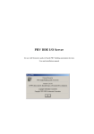
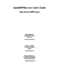
To install the MDLCGATE Server, run the DR44010_xxx.msi and proceed as directed by
the MDLCGATE Server Setup Wizard. The installation is simple and straightforward, only
it is important to select the correct protection (HASP key or software license) in “Custom
Setup” dialog:
The HASP key or software license key is needed for full time running of MDLCGATE
Server. The HASP key is an USB key (dongle) to be installed into PC USB port and
needs the SafeNet Sentinel LDK Run-time Environment (HASP HL Runtime Package) to
be installed and running – see details in “Licensing by using HASP HL key” section below.
The software license key is a 16-character alphanumeric “computer-dependent” string,
provided after purchasing the MDLCGATE Server (for more information, see “Software
license key” section below. Without HASP key installed or software license key entered,
the MDLCGATE Server will run one hour in demo mode. After purchasing the
MDLCGATE Server, the appropriate HASP key or software license key is provided and no
re-installation of MDLCGATE Server is needed.
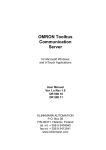
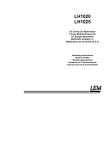
In case “HASP Device driver” and “HASP Files” are not selected then HASP USB key
will not be supported and only the software license will be available (files needed for
HASP USB key will not be installed):
MDLCGATE Server Ver1.x User Manual Rev 1.10
21010m110
Klinkmann Automation MDLC Gateway Communication Server
4
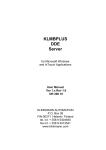
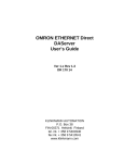
In case “HASP Device driver” and “HASP Files” are selected then HASP USB key will be
supported and both HASP-key and software license will be available (files needed for
HASP USB key will be installed):
Note: In case the SafeNet Sentinel LDK Run-time Environment (HASP HL Runtime
Package) is already installed on your computer (separately or by some other software)
then it can be disabled:
When installation is finished, the subdirectory specified as a folder where to install the
MDLCGATE Server files will contain the following files:
MDLCGATE.EXE
The MDLCGATE Server Program. This is a Microsoft Windows
32-bit application program.
MDLCGATE.CHM
The MDLCGATE Server Help file.
MDLCGATE.CFG
An example configuration file.
RTUTYPES.CFG
An example configuration file.
MSYSDEF.CFG
An example configuration file.
hasp_windows_44
42.dll
Dynamic Link Library installed only if “HASP Files” is selected
during the installation in “Custom Setup” dialog.
MDLCGATE Server Ver1.x User Manual Rev 1.10
21010m110
Klinkmann Automation MDLC Gateway Communication Server
5
haspdinst.exe
Sentinel LDK Run-time Environment Installer (HASP HL
Runtime Package), copied to MDLCGATE Server folder only if
“HASP Device driver” is selected during the installation in
“Custom Setup” dialog.
LICENSE.RTF
Klinkmann Automation software license file.
In case the “HASP Device driver” is selected during the installation in “Custom Setup”
dialog, the Sentinel LDK Run-time Environment (HASP HL Runtime Package) is installed
during the MDLCGATE Server installation (and will be uninstalled during the MDLCGATE
Server uninstallation). The presence of Sentinel LDK Run-time Environment can be
checked after the MDLCGATE Server installation by looking-up in Control Panel /
Administrative Tools Services – the Service “Sentinel Local License Manager” must be
started.
Notes:
1. The MDLCGATE Server is developed with Wonderware I/O Server Toolkit (ver 7,2,1,6)
and needs the Wonderware FS 2000 Common Components to be installed on
computer where the MDLCGATE Server is running. If using Wonderware InTouch 8.0 or
newer, install the FS 2000 Common Components before installing InTouch (see also
Wonderware Tech Notes 404 and 313). The Wonderware FS2000 Common Components
are installed automatically when any of Wonderware product (e.g. InTouch or some
Wonderware I/O server) is installed.
2. If MDLCGATE Server “Suite Link & DDE” version will run on PC where Wonderware
FS2000 Common Components are not installed then a special I/O Server Infrastructure
installation package can be obtained from Klinkmann (see Installing the I/O Server
Infrastructure section below). This I/O Server Infrastructure installation package contains
the minimum set of software needed to run the MDLCGATE Server and these
infrastructure files must be install prior to executing the MDLCGATE Server.The I/O
Server Infrastructure does not support using MDLCGATE Server as a Windows Service
and remote access to MDLCGATE Server (when DDE/SuiteLink Client is not located on
same computer as MDLCGATE Server).
To uninstall the MDLCGATE Server, start Control Panel, select “Uninstall a program”
(“Add/Remove Programs” on XP/2003) and select the “MDLCGATE SuiteLink and DDE
Server” from the list of available software products. Click on “Uninstall” (“Add/Remove…”
on XP/2003) and proceed as directed by the Uninstall Wizard.
Licensing by using HASP HL key
The following should be done to enable the licensing by HASP HL key:
-
-
The “HASP Device driver” and “HASP Files” are selected during the MDLCGATE
Server installation in “Custom Setup” dialog – that causes correspondingly
haspdinst.exe and hasp_windows_4442.dll files are copied to MDLCGATE Server
folder and Sentinel LDK Run-time Environment (HASP HL Runtime Package) is
installed and started, enabling the MDLCGATE Server can detect the HASP HL
USB dongle;
insert the received HASP key into USB port, and wait until “Installing device driver
software” message disappears and “Device driver software installed successfully”
message appears;
MDLCGATE Server Ver1.x User Manual Rev 1.10
21010m110
Klinkmann Automation MDLC Gateway Communication Server
-
6
start MDLCGATE Server and check - if “Sofware key or HASP HL key not found!”
message does not appear then it means everything is done correctly and
MDLCGATE Server runs in full mode with licensing by HASP HL key enabled.
Software license key
MDLCGATE Server supports the “computer dependent” software licensing. The
following steps are required to enable it:
1) Start MDLCGATE Server, click on "Help" menu item (also short-cut Alt+H can be used)
and pop-up menu with "Help" menu commands will appear:
Select “License” and “License” dialog will appear:
2) Here the “Customer PC Code” is “computer-dependent” string generated by
MDLCGATE Server and it is unique for this computer. Write it down or Copy/Paste to email when ordering the MDLCGATE Server.
3) After purchasing the MDLCGATE Server, you will get the software license key - 16character alphanumeric string. Open the “License” dialog again and Copy/Paste it to
“Software Key” field:
4) Click OK and restart MDLCGATE Server. MDLCGATE Server software license now is
enabled.
Note – the “Software Key” string is saved to MS Windows system directory (e.g.
C:\Windows) WIN.INI file [MDLCGATE] section to enable it is automatically detected at
MDLCGATE Server next start-up.
MDLCGATE Server Ver1.x User Manual Rev 1.10
21010m110
Klinkmann Automation MDLC Gateway Communication Server
7
Transferring the software license to other computer
The transfer of Software License Key might be needed in very rare situations when it is
necessary to move Klinkmann software to other computer (or operation system change is
planned for same computer). Such transfer PERMANENTLY removes the Software
License Key, so be very careful when deciding to use this option.
The following steps are required to transfer the Software License Key:
1) Start the MDLCGATE Server. For MDLCGATE Server “Suite Link & DDE” version,
the ArchestrA SMC Log Viewer (or Wonderware Logger) must be started. For
MDLCGATE Server “OPC & DDE” version, the MDLCGATE Internal Logger and
“Log to File” should be enabled (see “Troubleshooting menu” and “Internal
Logger”sections at the end of this manual). Select Help/License from main menu
and click the “Transfer” button on “License” dialog:
2) Confirm the transfer of Software License Key by clicking on Yes button:
The “License” dialog now will contain the empty “Customer PC Code” and
“Software Key” fields:
3) Take the screenshot from ArchestrA SMC Logger or MDLCGATE Internal Log file
window containing the “Software License Key removal message”, like below:
MDLCGATE Server Ver1.x User Manual Rev 1.10
21010m110
Klinkmann Automation MDLC Gateway Communication Server
8
or take the string with “Software License Key removal message” directly from
ArchestrA SMC Logger or MDLCGATE Internal Log file, like following:
Software Key 76e4-e909-8f10-9514 removed. PC Code: 2496-c475-8b8b-6291,
Product Code: DR21010 120
4) Provide the obtained “Software License Key removal message” screenshot or
string together with new “Customer PC Code” when applying for new Software
License Key without purchasing the new license (in situations when it is necessary
to move Klinkmann software to other computer or operation system change is
planned).
Note!
Without providing the “Software License Key removal message” screenshot or string, the
new Software License Key will not be assigned.
Starting the MDLCGATE Server
The Server can be started in some different ways:
(1) At MS Windows startup from Startup group;
(2) Manually - before client (Wonderware InTouch, MS Excel) startup;
(3) When starting client (e.g. Wonderware InTouch) with Server name in the path.
At Server startup the MDLC Gateway API function gwlib_init_api() is called to build the
internal data structure used to identify the MOSCAD system. The names of two files (RTU
Types Definition file and MOSCAD System Definition file) can be specified in the Server
command line or default file names RTUTYPES.CFG and MSYSDEF.CFG can be used.
For example, the following command will start the MDLCGATE Server with non-default
definition files:
mdlcgate mdlc_typ.cfg mdlc_sys.cfg
MDLCGATE Server Ver1.x User Manual Rev 1.10
21010m110
Klinkmann Automation MDLC Gateway Communication Server
9
where mdlc_typ.cfg is RTU Types Definition file and mdlc_sys.cfg is MOSCAD System
Definition file. The structure of these files is described in the MOSCAD System
Definition Files section.
Installing the I/O Server Infrastructure
The I/O Server Infrastructure installation package is supplied as a self-extracting archive
(IOServerInfrastructure.exe) and can be downloaded from Klinkmann’s web site.
To install the I/O Server Infrastructure from the self-extracting archive, run the
IOServerInfrastructure.exe and proceed as directed by the I/O Server Infrastructure
Setup program.
To uninstall the I/O Server Infrastructure, start Control Panel, select “Add/Remove
Programs” and select the “IO Server Infrastructure” from the list of available software
products. Click on “Add/Remove…” and proceed as directed by the UnInstallShield
program.
Note: The I/O Server Infrastructure installation will be rejected if Wonderware FS2000
Common Components are already installed on same computer. The I/O Server
Infrastructure does not support using MDLCGATE Server as a Windows Service and
remote access to MDLCGATE Server (when DDE/SuiteLink Client is not located on same
computer as MDLCGATE Server).
Configuring the MDLCGATE Server
After the MDLCGATE Server is initially installed, a small amount of configuration is
required. Configuring the Server automatically creates a MDLCGATE.CFG file that holds
all of the Gateway Node and Topic definitions entered. This file will automatically be
placed in the same directory in which the MDLCGATE Server is located unless the path
where the configuration file will be placed is specified via the /Configure/Server Settings...
command.
To perform the required configurations, start up the MDLCGATE Server. If the Server
starts up as an icon, double-click on the icon to open the Server's window. The following
will appear:
To access the commands used for the various configurations, open the /Configure menu:
MDLCGATE Server Ver1.x User Manual Rev 1.10
21010m110
Klinkmann Automation MDLC Gateway Communication Server
10
Note: The /Configure/Topic Definition... command invokes the configuration dialogs for
System's all Topics (for System's all Nodes if multiple gateways are used). To configure
Topics on a per Node basis the /Configure/Gateway Node Definition... command should
be invoked.
Server Settings Command
A number of parameters that control the internal operation of the Server can be set. In
most cases, the default settings for these parameters provide good performance and do
not require changing. However, they can be changed to fine-tune the Server for a specific
environment.
To change the Server's internal parameters, invoke the /Configure/Server Settings...
command. The "Server Settings" dialog box will appear:
The following describes each field in this dialog box:
Protocol Timer Tick
This field is used to change the frequency at which the Server is continuously activated
(the Server checks for work to do). If the computer is very busy or some other MS
Windows application is taking over the computer then the Server could be is activated
less frequently than the setting in the Protocol Timer Tick.
Note: The default value is 50. If a value lower than 50 is entered, the Server uses 50
milliseconds. For Windows NT the minimum value is 10 milliseconds.
NetDDE being used
Select this option if you are networking using NetDDE.
Configuration File Directory
Specify the path (disk drive and directory) in which MDLCGATE Server will save its
current configuration file. MDLCGATE Server will use this path to load the configuration
file the next time it is started.
Note: Only the "path" may be modified with this field. The configuration file is always
named MDLCGATE.CFG.
Note: There is no limit to the number of configuration files created, although each must be
in a separate directory. When using the MDLCGATE Server with InTouch, it is good
practice to place the configuration file in the application directory.
Once all entries have been made, click on OK.
MDLCGATE Server Ver1.x User Manual Rev 1.10
21010m110
Klinkmann Automation MDLC Gateway Communication Server
11
Gateway Node Definition Command
To configure the MDLC Gateway Node, invoke the /Configure/Gateway Node Definition...
command. The "MDLCGATE Gateway Node Settings" first dialog box will appear:
To modify or examine an existing Gateway Node, select the Node name and click on
Modify. To define a new Gateway Node, click on New. The "MDLCGATE Gateway Node
Settings" second dialog box will appear. The following is an example of "MDLCGATE
Gateway Node Settings" dialog box where the default configuration is entered (single
Primary Gateway, no Hot Standby):
The following describes each dialog field in this dialog box:
Gateway Node Name
Enter the Gateway Node name and later use it in Topic Definition.
MDLCGATE Server Ver1.x User Manual Rev 1.10
21010m110
Klinkmann Automation MDLC Gateway Communication Server
12
Computer Internet Address
Enter the Computer Internet Address (IP Address) if it has more than one. If there is only
one Internet Address for computer then Use Default can be checked to use this Address.
If Computer is multi-homed (more than one Internet Address used) and Use Default is
checked then it is impossible to know which Address must be used.
Primary Gateway IP Address
Enter the Primary Gateway Internet Address (IP Address).
Secondary Gateway IP Address
Enter the Secondary Gateway Internet Address (IP Address). If Not Used is checked then
Secondary Gateway is not used for this Gateway Node.
Reply Timeout
Enter the reply timeout value (in seconds) for the TCP/IP communications; this value is
used as a timeout parameter for the MDLC Gateway API function gwlib_receive_buffer().
Gateway Status Update Interval
Enter the interval (in seconds) at which the Gateway status (both for the Primary and
Secondary Gateways) will be read.
Max Pending Read Requests
The possibility to configure the maximum number of pending read requests which are
allowed to be sent to the Gateway. This parameter value depends on MOTOROLA
Gateway hardware model and current settings. In two Gateways using mode this number
cannot exceed weaker Gateway capacity. MDLCGATE Server allows set up to 128
pending read(poll) requests. Smallest possible value is 2(1 Gateway STATUS read(poll)
request and one regular read(poll) request). Default value is 20.
Max Pending Write Requests
The possibility to configure the maximum number of pending write requests which are
allowed to be sent to the Gateway. This parameter value depends on MOTOROLA
Gateway hardware model and current settings. In two Gateways using mode this number
cannot exceed weaker Gateway capacity. MDLCGATE Server allows set up to 128
pending write(command) requests. Smallest possible value is 1. Default value is 5.
Automatic Hot Standby
This setting enables or disables the “automatic hot standby” to indicate how the hot
standby is implemented; if this setting is ON (checkbox is checked) then hot standby is
processed by the Server; if this setting is OFF (checkbox is unchecked) then hot standby
must be processed by the client program using special items/points created for topic
GATEWAYS (see the Hot Standby - Principles of Operation and Item (Point) Naming
sections).
Topic(s)...
To configure only the current Gateway Node's Topics press the Topic(s)... pushbutton.
The "Topic Definition" dialog box (see the Topic Definition Section ) will appear. Up to
500 Topics can be configured for one Gateway Node.
MDLCGATE Server Ver1.x User Manual Rev 1.10
21010m110
Klinkmann Automation MDLC Gateway Communication Server
13
Notes:
1. The channel type opened both for Primary Gateway and (if configured) for Secondary
Gateway and used to send/receive poll messages and to receive burst messages is
GWLIB_BURST_CHANNEL_TYPE | GWLIB_SEND_CHANNEL_TYPE |
GWLIB_RECEIVE_CHANNEL_TYPE.
2. The Gateway status is requested at Gateway status update interval both for Primary
Gateway and (if configured) for Secondary Gateway. The data from all connected RTUs
are accessed through the Primary Gateway.
The following is an example of "MDLCGATE Gateway Node Settings" dialog box where
the Secondary Gateway IP Address is entered and Automatic Hot Standby is used:
Once all entries have been made, click on OK to process the configuration for the
Gateway Node. The "MDLCGATE Gateway Node Settings" first dialog box will appear
again.
Click on Done when configuration for all Gateway Nodes has been performed.
Note: If this is the first time the Gateway Nodes have been configured, the user will be
prompted to save configuration to an existing directory.
MDLCGATE Server Ver1.x User Manual Rev 1.10
21010m110
Klinkmann Automation MDLC Gateway Communication Server
14
Hot Standby - Principles of Operation
The MDLC Gateway redundancy is supported as an option to increase the reliability of the
system. Two MDLC Gateways can be configured in a Primary/Secondary mode. If
Primary Gateway is not available then Secondary Gateway can be used. Each Gateway
has to be configured with unique IP address. Also redundant Hosts (computers with
MDLC Gateway Server running) and redundant MDLC and LAN communication devices
can be used.
The following are examples of possible configurations:
1. A single Primary Gateway with a single Host. No MDLC Gateway redundancy. No
MDLC Gateway Server redundancy - the Server is running only on one computer.
2. A single Primary Gateway with multiple Hosts. No MDLC Gateway redundancy. The
redundant MDLC Gateway Servers are used - the Server is running on multiple
computers and if some of them fail then data from RTUs can sill be accessed by other
ones.
3. Dual redundant Primary/Secondary Gateway with a single Host. The MDLC Gateway
redundancy supported, no MDLC Gateway Server redundancy
4. Dual redundant Primary/Secondary Gateway with multiple Hosts. The MDLC Gateway
redundancy supported, redundant MDLC Gateway Servers are used.
Depending on necessary reliability level the above mentioned dual Gateway
configurations can be used with single communication device, with redundant
communication devices and with multiple redundant communication devices.
The Hot Standby feature, implemented in the MDLC Gateway Server, supports the
redundant MDLC Gateways in the following way.
1. After startup the Gateway status is requested at Gateway status update interval both
for Primary and Secondary Gateways. The data from all connected RTUs are accessed
through the Primary Gateway.
2. If the communication with Primary Gateway fails (no answer to gwlib_get_gw_status()
command or returned Gateway status is Secondary) then depending on the “automatic
hot standby” setting the hot standby is processed in the following way.
If “automatic hot standby” is ON and if communication with Secondary Gateway is O.K.
(returned status is GWLIB_SECONDARY) then Secondary Gateway is changed to
Primary (by MDLC Gateway API function) and data from all connected RTUs now are
accessed through this Gateway’s channels.
If “automatic hot standby” is OFF then the status of each Gateway can be monitored and
changed if special topic GATEWAYS containing items GS_LSB_xxx.xxx.xxx.xxx,
GS_MSB_xxx.xxx.xxx.xxx and GMODE_SET_ xxx.xxx.xxx.xxx (where
xxx.xxx.xxx.xxx is the Gateway IP address) is created (see the Item (Point) Naming
section). In this case if Primary Gateway fails and if Secondary Gateway status is O.K.
then GMODE_SET_ xxx.xxx.xxx.xxx (where xxx.xxx.xxx.xxx is the Secondary
MDLCGATE Server Ver1.x User Manual Rev 1.10
21010m110
Klinkmann Automation MDLC Gateway Communication Server
15
Gateway IP address) value must be switched from 0 to 1 and then Secondary Gateway is
changed to Primary.
3. The Primary Gateway can be set to Secondary by switching the Discrete item
GMODE_SET_ xxx.xxx.xxx.xxx value (where xxx.xxx.xxx.xxx is the Primary Gateway
IP address) to 0. The Secondary Gateway can be set to Primary by switching the Discrete
item GMODE_SET_ xxx.xxx.xxx.xxx value (where xxx.xxx.xxx.xxx is the Secondary
Gateway IP address) to 1.
Saving MDLCGATE Configuration File
If the configuration file does not currently exist, or a new configuration path has been
specified, the Server will display the "Save Configuration" dialog box:
This dialog box displays the path where the MDLCGATE Server is going to save the
current configuration file. The path may be changed if necessary. Also, the path can
optionally be recorded in the WIN.INI file by selecting the "Make this the default
configuration file" option. Doing so will allow the MDLCGATE Server to find the
configuration file automatically each time it is started. This option is available only when
the configuration file path is changed.
Configuration File Location
When the MDLCGATE Server starts up, it first attempts to locate its configuration file by,
first checking the WIN.INI file for a path that was previously specified. If the path is not
present in the WIN.INI file, the Server will assume that the current working directory is to
be used.
To start the Server from an application directory configuration file other than the default
configuration file a special switch (/d:) is used. For example, invoke the File/Run
command and enter the following:
MDLCGATE /d:c:\directoryname
Note: There is no limit to the number of configuration files that may be created, although
each must be in a separate directory.
MDLCGATE Server Ver1.x User Manual Rev 1.10
21010m110
Klinkmann Automation MDLC Gateway Communication Server
16
Topic Definition Command
The user provides each MOSCAD Remote Terminal Unit with an arbitrary name that is
used as the topic for all references to the RTU. More than one Topic can be defined for
the same RTU.
To define the Topics (MOSCAD RTUs) attached to one or more MDLC Gateways invoke
the /Configure/Topic Definition... command. The "Topic Definition" dialog box will
appear:
To modify or examine an existing topic, select the topic name and click on Modify. To
define a new topic, click on New. The "MDLCGATE Topic Definition" dialog box will
appear:
MDLCGATE Server Ver1.x User Manual Rev 1.10
21010m110
Klinkmann Automation MDLC Gateway Communication Server
17
The following describes each dialog field in this dialog box:
Topic Name
Enter the Topic Name that corresponds to the Topic Name in the "Access Name
Definition" dialog box described in the Using the MDLCGATE Server with InTouch
section.
“GATEWAYS” (Special Topic Name)
If this checkbox is checked then this is a special topic GATEWAYS containing only some
special predefined items (see the Item (Point) Naming section).
Gateway Node Name
Select the Gateway Node to associate it with the topic. Additional topics may be
associated with the same Gateway Node at a later time.
RTU Site ID
Enter this RTU Site ID. The corresponding value must be present in the MOSCAD
System Definition file.
RTU Type Name
This RTU Type Name (value from the RTU Types Definition file) is displayed here. The
new value can not be entered. This field is used only for information.
Poll mode
Select the poll mode (GWLIB_POLL_MODE or GWLIB_POLL_COS_MODE) used to
send poll requests to this RTU.
MDLCGATE Server Ver1.x User Manual Rev 1.10
21010m110
Klinkmann Automation MDLC Gateway Communication Server
18
MOSCAD RTU Update Interval
Enter the frequency (in configurable units (milliseconds, seconds, minutes, hours)) at
which the values of items will be read (polled) from this MOSCAD RTU.
Historical Data Update Interval
Enter the frequency (in seconds) at which the values of specially marked items (item/point
name with suffix h(or H)) will be stored in the historical file (see the sections Item (Point)
Naming and Historical File). The value is stored only if it has been changed.
"Ping" Status Update Interval
Enter the frequency (in seconds) at which this MOSCAD RTU status is requested. The
RTU status "ping" command requests this RTU first Table's (first Table is from the RTU
Types Definition file, not Table 1) first element (column 0, row 0). “Ping” request is
disabled if value of "Ping" Status Update Interval is 0.
Once all entries have been made, click on OK to process the configuration for the Topic.
The "Topic Definition" dialog box will appear again.
SUSPEND Topic On Start-Up
The MDLC Gateway Server supports the possibility to protect communication from data
flow impact at connection start-up. If SUSPEND checkbox is selected then no poll
messages of the topic will be sent. State of this "SUSPEND Topic On Start-Up" checkbox
is assigned to special "SUSPEND"(see Item(Point) Naming chapter) item of the Topic if
such item is activated in user's InTouch application. Further communication control can be
performed using SUSPEND item of corresponding topic: if value of item is set to 0 then
polling is stopped otherwise polling is executed in general way.
Note: This option does not take effect to write messages execution.
Clone of Topic
Since MDLCGATE supports up to 500 topics (per Gateway) the configuration of topics
could be time-consuming. It is possible to make clones (similar copies) of any topic
(except special GATEWAYS topic). Only difference between clone(s) and base topic is
name. Name can be generated by MDLCGATE Server or extracted from text file.
To clone some topic select it and press “Clone” button. “Topic Clone” dialog box will
appear:
MDLCGATE Server Ver1.x User Manual Rev 1.10
21010m110
Klinkmann Automation MDLC Gateway Communication Server
19
Topic to Clone
Appears topic name of cloned topic.
Number Of Clones
Enter the number of copies(clones) will be created.
Base Name
Enter the “Base Name” for created Topic Names. Name of created topic will be:
[BaseName]+[NumberOfClone].
Examples:
1)
if “Base Name” is SAMPLE and “Number of Clones” is 3 and “Pad with 0”
checkbox is not checked then will be created 3 topics with following names:
SAMPLE1, SAMPLE2, SAMPLE3.
2)
if “Base Name” is SAMPLE and “Number of Clones” is 3 and “Pad with 0”
checkbox is checked then will be created 3 topics with following names:
SAMPLE001, SAMPLE002, SAMPLE003.
File Name
To extracted clone name(s) from the text file check the radio button nearby “File Name”
static control. “Browse…” button and “File Name” static control and editbox becomes
enabled. Do not type the file name into “File Name” editbox but press “Browse…” button
to select the file with topic names.
Browse… and file format
To enter file name press “Browse…” button. “Load TXT file” common dialog box will
appear:
Select the file with topic names. The file with topic names must be plain text file previously
created by any text editor (e.g. NOTEPAD). Each line of such file must contain either one
topic name or comment. Comment starts by ‘;’ or ‘#’. Default file extension is *.TXT. The
following is contents of example file (names.txt):
RTU003
RTU2
RTU3
MDLCGATE Server Ver1.x User Manual Rev 1.10
21010m110
Klinkmann Automation MDLC Gateway Communication Server
20
RTU500
SIMULATOR
For topic creation press OK. Server will report about successfully created topics (number
of clones should be equal to Number of Clones configuration value). New topics will
appear in the Topic Definition window:
Update Interval for Multiple Topics
The MDLC Gateway Server supports the possibility to enter the new MOSCAD RTU
Update Interval value for multiple Topics in a single operation. At first these multiple
Topics must be selected in the "MDLCGATE Topic Definition" dialog box by holding the
CTRL key while clicking on the selected ones:
MDLCGATE Server Ver1.x User Manual Rev 1.10
21010m110
Klinkmann Automation MDLC Gateway Communication Server
21
Then click on Update Interval. The "UPDATE INTERVAL" dialog box will appear:
Enter the new value in the MOSCAD RTU Update Interval field and click on OK to
change this value for all selected Topics or click on Cancel. The "Topic Definition" dialog
box will appear again.
The MOSCAD RTU Update Interval can be change also at run-time, i.e. when Topics are
activated by client application (see Guidelines on Server Performance section).
Select Done when configuration for all MOSCAD RTUs has been performed.
MDLCGATE Server Ver1.x User Manual Rev 1.10
21010m110
Klinkmann Automation MDLC Gateway Communication Server
22
Guidelines on Server Performance
Depending on the complexity of the MOSCAD environment where the MDLC Gateway
Server is used, the following guidelines should help to achieve the optimum Server
performance.
Update Intervals
The optimum usage of Update Intervals is very important. There are three Update
Intervals (listed according to their priority) which greatly affect the performance of the
Server:
(1) Gateway Status Update Interval,
(2) "Ping" Status Update Interval,
(3) MOSCAD RTU Update Interval.
If Gateway Status and "Ping" Status Update Intervals are very short (less than one
second or for very complex systems less than ten seconds) and also data from RTUs are
requested very often (MOSCAD RTU Update Intervals also are some seconds), then it is
very possible that there is not enough time to execute all poll requests. 20 - 60 seconds
could be a reasonable value for Gateway Status and "Ping" Status Update Interval in not
too complex systems. Gateway Status poll and RTU Ping are intended for error detection.
Theoretically one poll should be equal up to three RTU Ping and up to ten Gateway
Status Intervals because it gives some time to Server for error processing. It should
protect the server from useless polling(reading) and writing.
The optimum MOSCAD RTU Update Interval value depends on the total number of
connected (active) RTUs to which poll requests are sent and also on total amount of
active items for the corresponding Topic. It is very difficult to suggest some default value
for MOSCAD RTU Update Interval because it highly depends on current environment.
This Update Interval must give enough time to execute all poll requests, receive burst
data and not to overload the system or the radio airtime usage. Typically RTU Update
Intervals in radio-based systems are 10-30 minutes or 1-12 hours depending on system
requirements.
Note: Unlike other SCADA systems MOSCAD uses an unsolicited, spontaneous burst
mechanism to update important data changes. Therefore it is less critical to poll RTUs
frequently.
QUEUE_IS_FULL_xxx.xxx.xxx.xxx item
The Server supports Discrete Read Only item QUEUE_IS_FULL_xxx.xxx.xxx.xxx
(where xxx.xxx.xxx.xxx is the Gateway IP address), used for indication of polling queue
or write queue overflow. This item is connected to whole active Gateway, not to some
RTU (special Topic "GATEWAYS" is used). This item value is OFF (0) if the current
number of poll requests for current active Gateway does not exceed Max Pending Poll
Requests (see chapter MDLCGATE Gateway Node Settings ) or if the current number
of pending write commands does not exceed Max Pending Write Requests (see chapter
MDLCGATE Gateway Node Settings ). This item value changes to ON (1) if there are
more than maximum pending poll requests or maximum write requests allowed for this
Gateway(Node).
If QUEUE_IS_FULL_xxx.xxx.xxx.xxx item is specified in the client application (e.g. in
InTouch) then the system load can be monitored. If QUEUE_IS_FULL_xxx.xxx.xxx.xxx
MDLCGATE Server Ver1.x User Manual Rev 1.10
21010m110
Klinkmann Automation MDLC Gateway Communication Server
23
is ON too long then operator can modify (increase) the MOSCAD RTU Update Interval
value for single or multiple Topics (see Changing MOSCAD RTU Update Interval at
run-time subsection).
RESET_QUEUE_xxx.xxx.xxx.xxx item
For special topic "GATEWAYS" one additional item "RESET_QUEUE_xxx.xxx.xxx.xxx",
(where xxx.xxx.xxx.xxx is the IP address of the Primary Gateway of the node) can be
used. This is a Read/Write discrete item. If this item value is changed from 0 to 1 then
both read and write queue will be reseted. After setting
"RESET_QUEUE_xxx.xxx.xxx.xxx" to 1 replies on previous requests are not expected.
The capacity of write requests queue becomes equal to “Max Pending Write Requests”
value and capacity of read(poll) requests queue becomes equal to “Max Pending Read
Requests” value. Value can be switched to 1 and both queues will be emptied. This
possibility is usable in case when data exchange is wavelike. Unreachable Gateway or
data flow impact can be a reason for non-answering requests. Such situation can be
recognized at communication silence when the special topic "GATEWAYS" items
READ_COUNTER_xxx.xxx.xxx.xxx does no become equal to “Max Pending Read
Request” or WRITE_COUNTER_xxx.xxx.xxx.xxx and does not become equal to “Max
Pending Write Request” (see chapter MDLCGATE Gateway Node Settings and chapter
Item(Point) Naming ). It means that servers performance is reduced (less and less
pending request can be sent) after each non-answered request because Server waits
FOREVER answer on the sent request(except Gateway Status message).
RESET_READS_xxx.xxx.xxx.xxx item
For special topic "GATEWAYS" one additional item "RESET_READS_xxx.xxx.xxx.xxx",
(where xxx.xxx.xxx.xxx is the IP address of the Primary Gateway of the node) can be
used. This is a Read/Write discrete item. If this item value is changed from 0 to 1 then
only read part of queue will be reseted. After setting "RESET_READS_xxx.xxx.xxx.xxx" to
1 replies on previous poll requests are not expected and
READ_COUNTER_xxx.xxx.xxx.xxx becomes equal to current Gateway Node Max
Pending Read Requests parameter value (see chapter MDLCGATE Gateway Node
Settings ).
RESET_WRITES_xxx.xxx.xxx.xxx item
For special topic "GATEWAYS" one additional item "RESET_WRITES_xxx.xxx.xxx.xxx",
(where xxx.xxx.xxx.xxx is the IP address of the Primary Gateway of the node) can be
used. This is a Read/Write discrete item. If this item value is changed from 0 to 1 then
only write part of queue will be reseted. After setting "RESET_WRITES_xxx.xxx.xxx.xxx"
to 1 replies on previous write requests are not expected and
WRITE_COUNTER_xxx.xxx.xxx.xxx becomes equal to current Gateway Node Max
Pending Write Requests value (see chapter MDLCGATE Gateway Node Settings ).
SUSPEND item
Discrete Read-Write item. Very important and usable possibility against wavelike data
flow impact. This item gives control on data exchanging. The initial value of the
SUSPEND item the MDLCGATE Server takes from the "SUSPEND Topic On Start-Up"
checkbox (see chapter MDLCGATE Topic Definition ). If value of item is 0 reads(polls)
executes in general way. If SUSPEND item value becomes 1 only writes of this topic will
be executed. Read(poll) requests can be executed only by item POLL_NOW using.
MDLCGATE Server Ver1.x User Manual Rev 1.10
21010m110
Klinkmann Automation MDLC Gateway Communication Server
24
POLL_NOW item
The Server supports Discrete Write Only item POLL_NOW, used for immediately one
time polling of all active items from some RTU. This one time polling can be used when
MOSCAD RTU Update Interval value has been changed at run-time and it is necessary to
receive fresh data from RTU before previous MOSCAD RTU Update Interval is elapsed.
At start-up the value of the POLL_NOW item is 0. The Server issued all poll messages of
corresponding topic when value of item changes from 0 to 1. The changing of
POLL_NOW value from 1 to 0 does not take effect.
Note: The Server does not change (resets) value from 1 to 0. This reset operation has to
be performed by client (e.g. InTouch).
Changing MOSCAD RTU Update Interval at run-time
At run-time the MOSCAD RTU Update Interval can be changed in two different ways:
(1) Manually for single or multiple Topics as described in the Topic Definition Command
section. In this case configurable units (milliseconds, seconds, minutes, hours) can be
used.
(2) In the client application for single Topic by defining the Integer Read/Write item
UPDATE_INTERVAL. If this item value is changed in the client application (e.g. manually
or by InTouch script) then the Server uses this value in the further processing of poll
requests. In this case only seconds can be used.
It is important to understand that new MOSCAD RTU Update Interval value becomes
effective only after the previous MOSCAD RTU Update Interval has elapsed, i.e. there is
no automatic all RTU data polling performed at Update Interval change. This is done in
order to prevent additional overload if the system is still overloaded (QUEUE_IS_FULL_
xxx.xxx.xxx.xxx is ON). To perform immediate poll when MOSCAD RTU Update Interval
has been changed the POLL_NOW item can be used.
Several MDLCGATE Servers connected to one Gateway.
It is possible to connect to one Gateway from two or more MDLCGATE Servers running
on different PCs. In this case several things has to be observed:
1) If Servers are communicating with same Gateway simultaneously then Max Pending
Read Requests and Max Pending Write Requests parameters must be set . These
parameters are set in the (see chapter MDLCGATE Gateway Node Settings ) on
each PC where Server is running. These parameters should be set according the
following rule: the sum of Max Pending Read Requests for all connected Servers
cannot exceed allowed capacity of pending poll requests of Gateway and the sum of
Max Pending Write Requests cannot exceed allowed capacity of pending write
requests of Gateway .
2) If Servers are communicating with Gateway not simultaneously (client performs
swapping from one Server to another) then Max Pending Read Requests can be up
to maximum of Gateways capacity of pending read requests and Max Pending Write
Requests can be up to Gateways capacity of pending write requests for each Server.
The Server is not resetting queue of requests when connection with Gateway by some
reason is lost. This allows to process replies after reconnecting. This feature usually is
not working during Servers swapping. When swapping is performed then queue of
requests of just connected Server must be reset because Server waits forever for
reply on sent request. The client (e.g. InTouch) must write value 1 to GATEWAYS
MDLCGATE Server Ver1.x User Manual Rev 1.10
21010m110
Klinkmann Automation MDLC Gateway Communication Server
25
topic special item RESET_QUEUE_xxx.xxx.xxx.xxx or write value 1 to GATEWAYS
topic special items RESET_READS_xxx.xxx.xxx.xxx and
RESET_WRITES_xxx.xxx.xxx.xxx. Reset ensures that queue of requests will be
empty and Server can send the total amount of poll (Max Pending Read Requests or
default value 20) and write requests (Max Pending Write Requests or default value
5).
MDLCGATE Server Ver1.x User Manual Rev 1.10
21010m110
Klinkmann Automation MDLC Gateway Communication Server
26
Item (Point) Naming
The MDLC Gateway Server item/point naming is based on information contained in the
RTU Types Definition file. The item/point name generally may be described as:
TzCxRy[TSn] [.b][h]
where:
z - table number;
x - number of column (starting from 0) in the table;
y - number of row (starting from 0) in the table;
TSn - used only if data type is Timestamp1 and Timestamp2 (n can be 1 or 2); for these
items the corresponding element type in the RTU Types Definition file must be float;
.b - optionally used address of bit if data type is Compressed Bits and only one bit must
be accessed;
h - (or H) optionally used suffix indicating that this item value will be stored in the historical
file.
Examples:
T1C2R0 - Column 2 Row 0 in Table 1;
T1C2R5h - Column 2 Row 5 in Table 1, values will be stored in the historical file;
T12C0R1.4 - bit 4 in Column 0 Row 1 in Table 12.
T12C0R1.4H - bit 4 in Column 0 R1 in Table 12, values will be stored in the historical file.
T1C2R0TS1 - Column 2 Row 0 in Table 1, data type is Timestamp1;
The following item types are supported.
Item Type
Bit
Bit in Compressed Bits
Compressed Bits
(represents a Row of
up to 8 Bits in a Table)
Analog
Float
TS1 Timestamp1
TS2 Timestamp2
Value Range
0,1
0,1
0...255
Type
Discrete
Discrete
Integer
-32768...32767
Standard IEEE 32
bit floating value
11 bytes long string
9 bytes long string
Integer
Real
Message
Message
Notes:
1. The Type is the item/point type used in the Wonderware InTouch.
2. The Bit in Compressed Bits, TS1 and TS2 are Read Only, all other types are Read
and Write.
3. The TS1 items have the format: “yy/mm/dd/hh” where yy is year (00...99), mm is
month (01...12), dd is day (01...31) and hh is hour(00...23).
4. The TS2 items have the format: “MM:SS:MSC” where MM is minutes (00...59), SS is
seconds (00...59) and MSC is milliseconds(000...999).
MDLCGATE Server Ver1.x User Manual Rev 1.10
21010m110
Klinkmann Automation MDLC Gateway Communication Server
27
The additional items/points can be used for special actions:
1. The special topic GATEWAYS items/points (xxx.xxx.xxx.xxx is the Gateway IP
address):
QUEUE_IS_FULL_xxx.xxx.xxx.xxx - Discrete, Read Only; used for indication of
polling queue overflow; this item value is 0 if the current number of poll requests for active
Gateway does not exceed Max Pending Read Requests(see chapter MDLCGATE
Gateway Node Settings ) ; this item value changes to 1 if there are more than Max
Pending Read Requests for this Gateway (see also Guidelines on Server
Performance section).
RESET_QUEUE_xxx.xxx.xxx.xxx - Discrete, Read-Write; used for reset of polling and
writing queue overflow; If this item value is changed from 0 to 1 then both read and write
queue will be reseted. After setting "RESET_QUEUE_xxx.xxx.xxx.xxx" to 1 replies on
previous requests are not expected. The capacity of write requests queue becomes equal
to Max Pending Write Requests(see chapter MDLCGATE Gateway Node Settings )
and capacity of read(poll) requests queue becomes equal to Max Pending Read
Requests. Value can be switched to 1 and both queues will be emptied. In case of
redundant Gateway use only Primary Gateway address in the item name because
RESET_QUEUE_xxx.xxx.xxx.xxx item belongs to MDLCGATE Gateway node (see also
Guidelines on Server Performance section).
READ_COUNTER_xxx.xxx.xxx.xxx - Integer, Read Only; used for monitoring of
read(poll) message queue; initial value of this item is Max Pending Read Requests (see
chapter MDLCGATE Gateway Node Settings ) .Value decrease by each read request
sending and increase by answer receiving. Value of item represents how many reads can
be sent to active Gateway. In the reads included active Gateway STATUS message. For
Gateway STATUS message one position is reserved because it must be sent in its
update interval. It means that actually amount of reads is Max Pending Read Requests 1. If value of item becomes 1 only Gateway STATUS message can be sent. In this case
the warning message “Read(Poll) Message Queue is FULL. Only GW STATUS can be
requested” appears in the WWLogger. If value of item is 0 read(poll) queue is full and
server waits for answer on sent requests. In case of redundant Gateway use only Primary
Gateway address in the item name because READ_COUNTER _xxx.xxx.xxx.xxx item
belongs to MDLCGATE Gateway node.
WRITE_COUNTER_xxx.xxx.xxx.xxx - Integer, Read Only; used for monitoring of write
message queue; initial value of this item is Max Pending Write Requests (see chapter
MDLCGATE Gateway Node Settings ). Value decreases by each write request sending
and increase by answer receiving. Value of item represents how many writes can be sent
to Gateway. If value of item is 0 write queue is full and server waits for answer on sent
requests. In this case the warning message “Write Pending Message Queue is FULL.”
appears in the WWLogger. In case of redundant Gateway use only Primary Gateway
address in the item name because WRITE_COUNTER_xxx.xxx.xxx.xxx item belongs to
MDLCGATE Gateway node.
GS_LSB_xxx.xxx.xxx.xxx - Integer, Read Only; used for storing of two LSBytes with
Gateway mode indications.
GS_MSB_xxx.xxx.xxx.xxx - Integer, Read Only; used for storing of two MSBytes with
Error and Warning indications.
MDLCGATE Server Ver1.x User Manual Rev 1.10
21010m110
Klinkmann Automation MDLC Gateway Communication Server
28
GMODE_SET_xxx.xxx.xxx.xxx - Discrete, used for setting of the Gateway operation
mode - when switched from 0 to 1 then MDLC Gateway API function gwlib_set_mode() is
called with mode set to GWLIB_PRIMARY_MODE; if switched from 1 to 0 then called with
mode set to GWLIB_SECONDARY_MODE.
SEND_ERROR _xxx.xxx.xxx.xxx - Integer, Read Only; used for storing of return values
from MDLC Gateway API functions gwlib_poll(), gwlib_send_data(),
gwlib_send_command(), gwlib_set_time(), gwlib_get_time();
RECEIVE_ERROR _xxx.xxx.xxx.xxx - Integer, Read Only; used for storing of return
values from MDLC Gateway API functions gwlib_receive_bufferl(), gwlib_get_message().
DUMP – Discrete; all information about gateway nodes, topics, messages and data items
are logged. This can be used to find out how many messages are actually sent to the
network.
Example:
GS_LSB_192.17.33.160 - Integer, Read Only; used for storing of Gateway mode
indication for the Gateway with IP address 192.17.33.160.
2. The special items/points which can be created for each topic (RTU):
POLL_NOW - Discrete, used for immediately one time polling of all active items (see
Guidelines on Server Performance section); this one time polling is performed when
POLL_NOW value switches from 0 to 1; no effect when switches from 1 to 0;
UPDATE_INTERVAL - Integer, used for run-time changing of MOSCAD RTU Update
Interval for this Topic (see Guidelines on Server Performance section);
SET_TIME - Discrete, used for downloading of Server date and time (by calling
gwlib_set_time) to a specified RTU;
GET_TIME - Discrete, used for uploading of a specified RTU date and time; the date and
time request (by calling MDLC Gateway API function gwlib_get_time) is sent when
GET_TIME value switches from 0 to 1; no effect when switches from 1 to 0; the result is
stored in the item DATE_TIME;
DATE_TIME - Message, Read Only; used for storing of character string containing the
specified RTU date and time in the following format: “YY/MM/DD hh:mm:ss” where YY is
year, MM - month, DD - day, hh - hours, mm - minutes and ss - seconds;
SUSPEND - Discrete, Read Write; used for suspending of poll messages of topic; value 0
allows poll message sending, but value 1 disables all current polls and only write
messages can be sent; poll can be executed to each topic by POLL_NOW = 1 (see also
Guidelines on Server Performance section);
MDLCGATE Server Ver1.x User Manual Rev 1.10
21010m110
Klinkmann Automation MDLC Gateway Communication Server
29
Historical File
Only data marked with suffix h(or H) are stored in the historical file. This file is updated at
the historical data update interval. The name of historical file is Hyymmdd.LOG where yy
is year, mm - month and dd - day. For example, H960702.LOG is the name of a historical
file with data received from all connected Gateways at July 2, 1996.
This single file record (row) contains a single received item data. The format of this
single file record is as follows:
yy/mm/dd,HH:MM:SS:MSEC,ID,STAT,TzCxRy,value
where: yy is year(00...99), mm - month (0...11), dd - day(1...31), HH - hours (00...23),
MM - minutes (00...59), SS - seconds (00...59), MSEC - milliseconds (000...999);
ID - RTU Site ID;
STAT - the RTU Status,
TzCxRy - the address of item (table, column and row),
value - received value.
If the same table contains TS1 and TS2 elements then RTU data and time are stored;
otherwise the computer data and time are stored.
The following would be an example of one this file record if RTU Site ID is 13, RTU Status
is 0, item address is Table 2 Column 5 Row 0 and received data value is 1:
96/02/07,09:48:40:760,13,0,T2C5R0,1
MDLCGATE Server Ver1.x User Manual Rev 1.10
21010m110
Klinkmann Automation MDLC Gateway Communication Server
30
Using the MDLCGATE Server with InTouch
To access items/points on the MOSCAD RTUs from InTouch, the Access names and
Tag names should be defined in WindowMaker.
Defining the DDE Access names
To define the Access Names in WindowMaker for each node invoke the /Special/Access
Names... command. The "Access Names" dialog box will appear.
Click on Add. The "Add Access Name" Dialog Box will appear:
Note. If Add is selected, this dialogue box will be blank when it initially appears. Data has
been entered here to illustrate the entries that are made.
The following fields are required entries when entering an Access Name Definition:
Access Name
Enter an arbitrary name that will be used by InTouch to refer to the topic. For simplicity, it
is recommended that the name defined for the topic in MDLCGATE Server also be to be
used here.
MDLCGATE Server Ver1.x User Manual Rev 1.10
21010m110
Klinkmann Automation MDLC Gateway Communication Server
31
Node Name
If the data resides in a network I/O Server, in the Node Name box, type the remote node's
name.
Application Name
In the Application Name box, type the actual program name for the I/O Server program
from which the data values will be acquired. In case the values are coming from the
MDLCGATE Server the MDLCGATE is used. Do not enter the .exe extension portion of
the program name.
Topic Name
Enter the name defined for the topic in the MDLCGATE Server to identify the topic the
MDLCGATE Server will be accessing. The Topic Name is an application-specific subgroup of data elements. In the case of data coming from a MDLCGATE Server program,
the topic name is the exact same name configured for the topic in the MDLCGATE
Server.
Note: This will usually be the same as the "Access Name", although, if desired, they may
be different. However, it must be the same name used when the topics were configured in
section Configuring the MDLCGATE Server.
Which protocol to use
Select the protocol (DDE or SuiteLink) that you are using.
When to advise server
Select Advise all items if you want the Server program to poll for all data whether or not
it is in visible windows, alarmed, logged, trended or used in a script. Selecting this option
will impact performance, therefore its use is not recommended.
Select Advise only active items if you want the Server program to poll only points in
visible windows and points that are alarmed, logged, trended or used in any script.
Click OK to accept the new Access Name and close the “Add Access Name” dialogue
box. The “Access Names” dialogue box will reappear displaying the new Access Name
selected in the list.
Click Close to close the “Access Names” dialogue box.
MDLCGATE Server Ver1.x User Manual Rev 1.10
21010m110
Klinkmann Automation MDLC Gateway Communication Server
32
Defining the Tag Names
To define the Tag names associated with the new "Access Name", invoke the
/Special/Tagname Dictionary... command (in WindowMaker). The "Tagname Dictionary "
dialogue box will appear:
Click on New and enter the Tagname. (The tagname defined here is the name InTouch
will use. The MDLCGATE Server does not see this name.)
Select the tag type by clicking on the Type: … button. The "Tag Types" dialogue box will
appear:
To access MDLCGATE device items, the type must be I/O Discrete, I/O Integer or I/O
Message. Select the Tag type.
The "Details" dialogue box for the tagname will appear:
MDLCGATE Server Ver1.x User Manual Rev 1.10
21010m110
Klinkmann Automation MDLC Gateway Communication Server
33
Select the Access name for MDLCGATE Server by clicking on the Access Name: …
button. The "Access Names" dialogue box will appear:
Select the appropriate Access Name and click on Close. (If the Access Name has not
been defined as previously described, click on Add… and define the Access Name now.)
The "Details" dialogue box will appear displaying the selected Access Name:
For integers fill in the Min EU, Max EU, Min Raw and Max Raw fields. These fields
control the range of values that will be accepted from the Server and how the values are
scaled. If no scaling is desired, Min EU should be equal to Min Raw and Max EU equal to
Max Raw.
Enter the MDLCGATE item name to be associated with this tagname in the Item: field in
the "Details" box:
MDLCGATE Server Ver1.x User Manual Rev 1.10
21010m110
Klinkmann Automation MDLC Gateway Communication Server
34
(Refer to the Item Names section for complete details.)
Where applicable, the Use Tagname as Item Name option may be selected to enter
automatically the tag name in this field.
Note: The tag name can only be used if it follows the conventions listed in the Item
Names section.
Once all entries have been made, click on the Save button (in the top dialogue box) to
accept the new tag name. To define additional tagnames click on the New button. To
return to the WindowMaker main screen, select Close.
Monitoring the Status of Communication with InTouch
InTouch supports built-in topic names called DDEStatus and IOStatus that are used to
monitor the status of communications between the Server and InTouch. For more
information on the built-in topic names DDEStatus and IOStatus, see your online “InTouch
User’s Guide”.
The status of communication between the Server and InTouch can be read into Excel by
entering the following DDE reference formula in a cell on a spreadsheet (in following
examples RTU1 is the Topic Name configured for MDLCGATE Server):
=view|DDEStatus!RTU1
or
=view|IOStatus!RTU1
MDLCGATE Server Ver1.x User Manual Rev 1.10
21010m110
Klinkmann Automation MDLC Gateway Communication Server
35
Notes on Using Microsoft Excel
Data from MDLCGATE topics (RTUs) may be accessed from Excel spreadsheets. To do
so, enter a formula like the following into a cell on the spreadsheet.
=MDLCGATE|topic!item
Sometimes, Excel requires the topic and/or item/points to be surrounded by apostrophes.
In the formula, topic must be replaced with one of the valid topic names defined during
the Server configuration process. Replace item with one of the valid item/point names
described in the Item (Point) Naming section.
Reading Values into Excel Spreadsheets
Values may be read directly into Excel spreadsheets by entering a DDE formatted formula
into a cell, as shown in the following examples:
=MDLCGATE|'RTU2'!' T1C2R0'
=MDLCGATE|' RTU3'!' T2C5R1.3'
=MDLCGATE|' RTU10'!' T1C2R0TS2'
Note: Refer to the Microsoft Excel manual for complete details on entering Remote
Reference formulas for cells.
Writing Values to MDLCGATE Points
Values may be written to the Server from Microsoft Excel by creating an Excel macro that
uses the POKE command. The proper command is entered in Excel as follows:
channel=INITIATE("MDLCGATE","topicname")
=POKE(channel,"itemname", Data_Reference)
=TERMINATE (channel)
=RETURN()
The following describes each of the above POKE macro statements:
channel=INITIATE("MDLCGATE","topicname")
Opens a channel to a specific topic name (defined in the Server) in an application with
name MDLCGATE (the executable name less the .EXE) and assigns the number of that
opened channel to channel.
Note: By using the channel=INITIATE statement the word channel must be used in
the =POKE statement instead of the actual cell reference. The "applicationname"
and "topicname" portions of the formula must be enclosed in quotation marks.
=POKE(channel,"itemname", Data_Reference)
POKEs the value contained in the Data_Reference to the specific operand in the
MDLCGATE via the channel number returned by the previously executed INITIATE
function. Data_Reference is the row/column ID of the cell containing the data value. For
"itemname", use some of the valid item names specified like described in the Item
Names section.
MDLCGATE Server Ver1.x User Manual Rev 1.10
21010m110
Klinkmann Automation MDLC Gateway Communication Server
36
=TERMINATE(channel)
Closes the channel at the end of the macro. Some applications have a limited number of
channels. Therefore they should be closed when finished. Channel is the channel
number returned by the previously executed INITIATE function.
=RETURN()
Marks the end of the macro.
The following is an example of Excel macro used to poke value from cell B2 to topic
RTU1 item T1C0R0:
PokeMacro –Ctrl a
=INITIATE("MDLCGATE","RTU1")
=POKE(A2,"T1C0R0",B2)
=ON.TIME(NOW()+0.01,"TerminateDDEChannel")
=RETURN()
TerminateDDEChannel
=TERMINATE(A2)
=RETURN()
Note: Refer to the Microsoft Excel manual for complete details on entering Remote
Reference formulas for cells.
Troubleshooting
WIN.INI entries
The first time you run the MDLCGATE Server configuration, most of the items in the
following list will automatically appear in the WIN.INI file. It is usually in the C:\WINDOWS
directory. It is an ASCII file and can be altered manually if you wish with any text editor,
e.g., MS Windows Notepad (do not use a program that formats text, such as MS Word or
Write unless the file is saved as DOS text). The following is a typical entry for the
MDLCGATE Server:
[MDLCGATE]
ProtocolTimer=50
ConfigurationFile=C:\MDLCGATE\
WinIconic=0
WinFullScreen=0
WinTop=112
WinLeft=0
WinWidth=200
WinHeight=168
DebugMenu=1
ShowSend=0
ShowReceive=0
ShowErrors=1
DumpScreen=0
MDLCGATE Server Ver1.x User Manual Rev 1.10
Protocol Timer Tick
Configuration File Path
Server starts up minimized (if 1)
Server starts up maximized (if 1)
Position and size of Server’s window at
Server startup (if not minimized or
maximized)
Show Troubleshooting menu (if 1)
ShowSend is checked (if 1)
ShowReceive is checked (if 1)
ShowErrors is checked (if 1)
DumpScreen is checked (if 1)
21010m110
Klinkmann Automation MDLC Gateway Communication Server
37
Following optional entries for MDLCGATE Server can be used if default values of
parameters must be changed:
DelayAfterLostRequest=10
Time in seconds of delay after LOST
REQUEST message received from
Gateway till next request sending. Value
can be from 1 to 65535 seconds.
LogSend=1
The possibility to configure which subitem
of the “Log Send” system menu item will
be selected at start-up. Subitems has the
following values:
"Log All Data" = 1;
"Custom Log" = 2;
"No Logging" = 0.
At Server first start-up the default
selection is "No Logging".
LogReceive=1
The possibility to configure which subitem
of the “Log Receive” system menu item
will be selected at start-up. Subitems has
the following values:
"Log All Data" = 1;
"Custom Log" = 2;
"No Logging" = 0.
At Server first start-up the default
selection is "No Logging".
MultiWrite=0
Can be used in cases when write
command execution order is important for
user application the Server must be
configured to transfer only one nonanswered write message to each topic.
Value 0 enables only one non-answered
write sending to each topic. In this case
Max Pending Write Request
parameter(see chapter MDLCGATE
Gateway Node Settings ) value is
disabled. Default value of MultiWrite is 1.
WarningOnPollMiss=1
Can be used in cases when it is
necessary to see that general poll issue is
missed. Parameter has two valid values:
0 - Off;
1 - On.
Default parameter value is 0. If above
described situation presents then
warning message should appear in the
WWLogger file. For example:
98/07/09 09:30:00.227/MDLCGATE/GW
node:Node2 Topic:RTU01 Table:1.
MDLCGATE Server Ver1.x User Manual Rev 1.10
21010m110
Klinkmann Automation MDLC Gateway Communication Server
38
Missed Poll Issue during Update
Interval(900 seconds)
WarningOnPollDelay=5
Can be used in cases when it is
necessary to see that general poll issue is
not missed yet but only delayed some
time. Valid values of parameter are
between 0 and 86400 seconds. No
message will be logged if value is 0.
Default this parameter value is 0. If above
string is included then warning message
should appear in the WWLogger file. For
example:
98/07/09 09:15:05.215/MDLCGATE/GW
node:Node2, Topic:RTU01, Table:1. Poll
issue delay is 5 seconds.
DelayBetweenPolls=600
The possibility to configure special poll
mode. Value can be from 0 to 86400
seconds. Value 0 of this parameter
means that general polling mode is used
and poll execution depends on update
interval. Non-zero value defines time
interval in seconds between STARTINGS
of each consecutively processed topic
polling (not between last request of
currently processed topic and the first
request of the next topic). Topics are
polled consecutively (one by one) in the
order of the initiation. If parameter
DelayBetweenPolls appears in the
MDLCGATE section of the WIN.INI file
and its value differs from 0 then following
changes in the Server performance are
expected:
1) All topics are suspended. Value of
SUSPEND item for each topic is equal to
1
and cannot be changed.
2) MOSCAD RTU Update Interval is
disabled.
3) Ping Update Interval is disabled. The
“Pings to RTU” are not executed.
Writes are executed in general way.
FirstBadTryMsgBox=0
MDLCGATE Server Ver1.x User Manual Rev 1.10
The possibility to disable the first
connection alert message box. Default
value is 1.
21010m110
Klinkmann Automation MDLC Gateway Communication Server
ResetMode=0
39
If this parameter value is 0 the pending
requests queue will be emptied when no
connection to Gateways happens. Default
value is 1,ie, MDLCGATE Server
remembers pending request numbers till
the Server shutdown. Only by reset
command can clear pending(read and
write) requests queue(see chapter Item
(Point) Naming ).
Troubleshooting menu
The following debugging choices are appended to the Server’s System Menu (the menu
that appears when you click the “-” box in the upper left hand corner of the Server
window):
Suspend Protocol/Resume Protocol - these choices permit you to turn protocol
processing on and off, which means that you can suspend access to
the RTUs.
Log Send
- this system menu item is provided for organizing of send package
logging to the WWLogger file. This item has the following subitems:
“Log All Data”, "Custom Log", "No Logging".
Log All Data
- if checked then all outgoing user data is logged to the WWLogger
file. Each message's log contains 1 or more strings. First string format
differs from each next ones of message's log. First string of
message's log has the following format(date, time and application
name are skipped):
<type of request>:<node name> < contents of request> size:<size
of request> mailbox:<#>- <request in hexadecimal format>
where
<type of request> - "Poll" or "Write" types of request are possible
<node name> - name of sender node
<contents of request>:
1. For Gateway status poll message - in the following format:
<GW <#> STATUS>,
where # is ‘I’ for PRIMARY ‘II’ for SECONDARY Gateway.
2. For Poll or Write requests format is the following:
<<Topic Name> Table:<#> StartRow:<#> EndRow:<#>
StartCol:<#> EndCol:<#>>. Request contains the Name of
sender Topic and the RTU table number. The StartRow and
EndRow shows the smallest and the greatest row numbers of
active items of the table of the topic. The StartCol and EndCol
shows the smallest and the greatest column numbers of active
items of the table of the topic.
MDLCGATE Server Ver1.x User Manual Rev 1.10
21010m110
Klinkmann Automation MDLC Gateway Communication Server
40
3. For "PING" of topic poll message in the following format:
<<Topic Name> PING>, where
<Topic Name> - name of sender topic.
<size of request> - size of request in bytes
<#> - number of mailbox for request and reply
<request in hexadecimal format> - hexadecimal queue of the
request
For example, the Gateway Status request number 144 for node Node2:
Poll(mailbox:144):Node2 GW I STATUS(size:36):00 01 7F FD 00 00...
Each next string of log (if such is necessary) has the following format:
<type of request>+:<request in hexadecimal format>
where
<type of request> - "Poll" or "Write" type (same as in the first string of
the log)
<request in hexadecimal format> - continuation of the hexadecimal
queue of the request
For example:
Poll+:00 00 00 00...
Custom Log
No Logging
- messages will be logged to the WWLogger corresponding to settings
in the Server's main window;
- no messages will be logged to the WWLogger;
When the Server starts the default selection is "No Logging". This
default value can be changed by settings in the WIN.INI file. Subitems
has the following values:
"Log All Data" = 1;
"Custom Log" = 2;
"No Logging" = 0.
The following is an example for "Log All Data" subitem selection in the
Server's system menu:
[MDLCGATE]
LogSend=1
Show Receive
- this system menu item is provided for organizing of received package
logging to the WWLogger file. This item has the following subitems:
“Log All Data”, "Custom Log", "No Logging".
Log All Data
- if checked then all incoming user data is logged to the WWLogger
file. Each message's log contains 1 or more strings. First string format
differs from each next ones of message's log. First string of
message's log has the following format:
MDLCGATE Server Ver1.x User Manual Rev 1.10
21010m110
Klinkmann Automation MDLC Gateway Communication Server
41
<type of message>:<node name> size:<size of message>-<
contents of message> [mailbox:<#>]- <message in hexadecimal
format>
where
<type of message> - "Receive" or "Burst" types of message are
possible
<node name> - name of receiver node
<size of request> - size of received message in bytes
<contents of message>:
1. Reply (acknowledge) on the Gateway status or mode poll
contains the following string: "GET_MODE_ACK or
GET_STATUS_ACK".
2. Reply (acknowledge) format on Poll, PING, Set time, Get
time, Write and request is the following:
<<Topic Name> <acknowledge type>>. Request
contains the name of sender Topic and type of acknowledge
(“POLL_ACK”,“GET_TIME_ACK”,”SET_TIME_ACK”,
”COMMAND_ACK”).
3. For "Burst"(unsolicited) message in the following format:
<<Topic Name> BURST_MSG>, where
<Topic Name> - the name of sender topic.
<(mailbox:<#>)> - the number of mailbox for "Receive" type of
message. This parameter is not used for “Burst” messages
<request in hexadecimal format> - the hexadecimal queue of the
request
Custom Log
- messages will be logged to the WWLogger corresponding to settings
in the Server's main window.
No Logging
- no messages will be logged to the WWLogger.
At Server first start-up the default selection is "No Logging". This
default value can be changed by settings in the WIN.INI file. Subitems
has the following values:
"Log All Data" = 1;
"Custom Log" = 2;
"No Logging" = 0.
The following is an example for "Log All Data" subitem selection in the
Server's system menu.
[MDLCGATE]
LogReceive=1
MDLCGATE Server Ver1.x User Manual Rev 1.10
21010m110
Klinkmann Automation MDLC Gateway Communication Server
42
Show Errors
Dump
- if checked then all information about errors is logged.
- all information about gateway nodes, topics, messages and data
items are logged. This can be used to find out how many messages
are actually sent to the network.
Dump Screen
- if checked then information about open connections and active
messages is displayed as a tree of communication component
structure and it is drawn in the Server's main window.
where
- "Gateways Nodes" and special topic "Gateways"
- Initialized Topic Name and Topic ID
- Log On. Shows which type of data (“Send”, ”Receive”, ”Burst”) will be logged
- Log Off. Shows which type of data (“Send”, ”Receive”, ”Burst”) will be not logged
"Log On” or “Log Off” mode can be set by mouse left button double click on the item.
These settings are in use if "Custom Log" menu subitem of "Log Send"/”Log Receive”
menu item is selected in the Server's system menu.
- Requests:
"STATUS I" - item shows "Gateway Status Poll Message" with it’s last mailbox
number.
"STATUS II" - item shows "Redundant Gateway Status Poll Message" (if redundant
Gateway is configured) with it’s last mailbox number.
"Ping" - item shows Topic Ping Status message with its last mailbox number.
“Read Message” - item shows general read message in the following format:
R T<#> R<s#>-R<e#> C<s#>-C<e#> mb<#>
Where
R - letter representing the read message;
T<#> - table number (from Rtutypes.cfg);
R<s#> - from which row the message starts (start row);
R<e#> - which row is the last in the message (end row);
C<s#> - from which column (from Rtutypes.cfg) the message starts (start column);
MDLCGATE Server Ver1.x User Manual Rev 1.10
21010m110
Klinkmann Automation MDLC Gateway Communication Server
43
C<e#> - which column (from Rtutypes.cfg) is the last in the message (end column);
mb<#> - last mailbox number of poll (read) message.
Note: Read message disappears when the last item is unadvised.
“Write Message” - item shows general write message in the following format:
W T<#> R<s#>-R<e#> C<s#>-C<e#> mb<#>
Where
W - letter representing the write message;
T<#> - table number (from Rtutypes.cfg);
R<s#> - from which row the message starts (start row);
R<e#> - which row is last in the message (end row);
C<s#> - from which column (from Rtutypes.cfg) the message starts (start column);
C<e#> - which column (from Rtutypes.cfg) is last in the message (end column);
mb<#> - last mailbox number of poll (read) message.
Note: Write message disappears when reply is received.
By mouse right button clicking it is possible to access the submenu. The submenu
contains the following items:
Log All Sends - selects all "Log Send" treeview items of topics of the current gateway
node.
Log All Receives - selects all "Log Receive" treeview items of topics of the current
gateway node.
Log All Bursts - selects all "Log Burst" treeview items of topics of the current gateway
node.
No Log Sends - unselects all "Log Send" treeview items of topics of the current gateway
node.
No Log Receives - unselects all "Log Receive" treeview items of topics of the current
gateway node.
No Log Bursts - unselects all "Log Burst" treeview items of topics of the current gateway
node.
Dump - dump internal data of the Server to WWLogger. Data will be logged depending on
treeview item that is under mouse cursor (the clicking on topic initiates the internal info
logging for this topic).
All debug information (except Dump Screen) is displayed via the Wonderware Logger,
which must be active for these commands to work.
Warning: if you check Log Send/Log All Data and/or Log Receive/Log All Data debug
output grows very fast and it is possible that computer becomes very slow.
MDLCGATE Server Ver1.x User Manual Rev 1.10
21010m110
Klinkmann Automation MDLC Gateway Communication Server
44
MOSCAD System Definition Files
The definition of the entire MOSCAD System (all RTUs for all Gateway Nodes) is stored
in the two files:
1. RTU Types Definition file.
2. MOSCAD System Definition file.
RTU Types Definition
In the RTU Types Definition file the RTU TYPES in the MOSCAD System are defined.
Each RTU Type Definition includes:
I. Number of Tables
II. For each Table:
A. Table Number (in the MOSCAD application)
B. Number of columns in the Table
C. Type of each column
The file is case insensitive.
;----------------------------------; File Type & Version
;----------------------------------*File_Type =RTU_TYPE
*Version=XXX
;----------------------------------; Definition of Types
;
;----------------------------------* No_of_Types=Nt
;
;----------------------------------;Definition for Type No ;
;----------------------------------*Type_name No_of_tables
;
;-----------------------------------------------;Definition for Table No j. in Type No ;
;-----------------------------------------------* Table_no No_of_columns Column_type_0 ... Column_type_i
MDLCGATE Server Ver1.x User Manual Rev 1.10
21010m110
Klinkmann Automation MDLC Gateway Communication Server
45
Example:
;RTU Types File Version
FILE_TYPE RTU_TYPE
VERSION 1.0
; Definition of RTU Types
Number_of_Types 3
;
;
;
Type_name No_of_tables
Type Pump 3
;
;
Table_no N_cols Col_0 Col_1 Col_2 Col_3 Col_4 Col_5 Col_6 Col_7
Table 0
5
Bit
Bit
Bit
Bit
Bit
Table 2
8
C_Bit C_Bit C_Bit C_Bit C_Bit C_Bit C_Bit C_Bit
Table 3
3
Float Val
Bit
;
;
Type_name No_of_tables
Type Valve 1
;
;
Table_no N_cols Col_0 Col_1 Col_2 Col_3 Col_4 Col_5 Col_6 Col_7
Table 10
3
Float Val
Bit
;
Type_name No_of_tables
;
Type PoleTop
1
;
;
Table_no N_cols Col_0 Col_1 Col_2 Col_3 Col_4 Col_5 Col_6 Col_7
Table 1
1
Bit
MDLCGATE Server Ver1.x User Manual Rev 1.10
21010m110
Klinkmann Automation MDLC Gateway Communication Server
46
MOSCAD System Definition
In the MOSCAD System Definition file the association of RTU - 'RTU Type' is defined.
Each RTU (defined by its Site_id) is assigned an 'RTU Type' (defined in the RTU Types
Definition file).
The file is case insensitive.
;---------------------------------;File Version
;---------------------------------*File_Type=SYSTEM
*Version=XXX
;---------------------------------;Definition of RTUs
;
;---------------------------------*No_of_Rtus
;
;---------------------------------;Definition for RTU No. i ;
;---------------------------------* Site_id
Type_name
Example:
;MOSCAD System File Version
FILE_TYPE SYSTEM
VERSION 1.0
;
No of RTUs
N_RTU
4
;
;
Site_id
Type_name
RTU 1
Pump
RTU 2
Pump
RTU 3
PoleTop
RTU 4
Valve
MDLCGATE Server Ver1.x User Manual Rev 1.10
21010m110
Klinkmann Automation MDLC Gateway Communication Server
47
KLINKMANN AUTOMATION
MDLC Gateway DDE Server
ReMDLCGATE History
Sep 96
Nov 96
Rev 1.0
Rev 1.1
Dec 96
Feb 97
Sep 97
Oct 97
Rev 1.2
Rev 1.3
Rev 1.4
Rev 1.5
Oct 98
Rev 1.6
Mar 2000
Rev 1.7
Apr 2000
Rev 1.8
Mar 2002
Jun 2014
Rev 1.9
Rev 1.10
First Release
Hot Standby - Principles of Operation section added.
Guidelines on Server Performance section added.
Installing and starting the MDLCGATE Server section
modified.
Gateway Node Definition Command section modified.
Topic Definition Command section modified.
Historical File section modified.
Item (Point) Naming section modified.
Manual file name changed. Minor changes.
Changes in Item(Point) Names section added.
Topic Definition Command section modified.
Troubleshooting Menu section modified.
Troubleshooting section modified.
Topic Definition Command section modified.
Guidelines on server performance section modified.
Item(point) naming section modified.
Item(point) naming section modified.
Gateway Node Definition Command section modified.
Communication Protocols section modified.
Other minor changes.
Suite Link support added. Max Pending Read and Write
Requests added in MDLCGATE Gateway Node Settings"
dialog.
Installation from CD information added.
“Installing and starting the MDLCGATE Server” section
modified, “Licensing by using HASP HL key” and “Software
license key” sub-sections added.
MDLCGATE Server Ver1.x User Manual Rev 1.10
21010m110