1
Air Conditioning
Clinic
Absorption
Water Chillers
One of the Equipment Series
TRG-TRC011-EN
Absorption
Water Chillers
One of the Equipment Series
A publication of
The Trane Company—
Worldwide Applied Systems Group
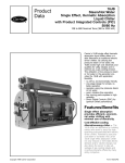
Preface
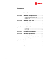
Figure 1
The Trane Company believes that it is incumbent on manufacturers to serve the
industry by regularly disseminating information gathered through laboratory
research, testing programs, and field experience.
The Trane Air Conditioning Clinic series is one means of knowledge sharing. It
is intended to acquaint a nontechnical audience with various fundamental
aspects of heating, ventilating, and air conditioning. We have taken special care
to make the clinic as uncommercial and straightforward as possible.
Illustrations of Trane products only appear in cases where they help convey the
message contained in the accompanying text.
This particular clinic introduces the concept of absorption water chillers.
ii
© 2000 American Standard Inc. All rights reserved
TRG-TRC011-EN
Contents
Introduction ........................................................... 1
period one
Absorption Refrigeration Cycle ....................... 3
Absorption System Fluids ........................................ 6
Components of the Absorption Cycle ...................... 8
Equilibrium Chart ................................................... 15
period two
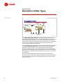
Absorption Chiller Types ................................. 18
Single-Effect Chiller ............................................... 19
Double-Effect Chiller ............................................. 21
Direct-Fired Chiller ................................................. 27
Chiller/Heater ........................................................ 30
period three Capacity Control ................................................. 34
Crystallization ........................................................ 37
Purge System ....................................................... 44
period four
Maintenance Considerations .......................... 46
period five
Application Considerations ............................. 53
Cooling-Water Temperature Limitations ................. 54
Combination Chiller Plants ..................................... 55
Special Considerations for Direct-Fired Chillers ...... 57
Equipment Rating Standards ................................. 59
period six
Review ................................................................... 60
Quiz ......................................................................... 65
Answers ................................................................ 68
Glossary ................................................................ 69
TRG-TRC011-EN
iii
iv
TRG-TRC004-EN
Introduction
notes
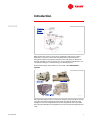
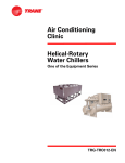
Figure 2
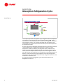
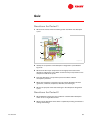
Water chillers are used in a variety of air conditioning and process cooling
applications. They are used to make cold water that can be transported
throughout a facility using pumps and pipes. This cold water can be passed
through the tubes of coils to cool the air in an air conditioning application, or it
can provide cooling for a manufacturing or industrial process.
Systems that employ water chillers are commonly called chilled-water
systems.
Figure 3
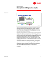
Although water chillers come in many sizes and types, they all produce cooling
using the same basic principles of heat transfer and change-of-phase of the
refrigerant. This is accomplished by the chiller refrigeration cycle. They differ
from each other based on the refrigeration cycle and the type of refrigerant fluid
used.
TRG-TRC011-EN
1
Introduction
notes
Water chillers using the vapor-compression refrigeration cycle vary by the type
of compressor used. The compressor works to draw in refrigerant vapor and
increase its pressure and temperature to create the cooling effect.
Reciprocating, scroll, helical-rotary (or screw), or centrifugal compressors are
generally used in water chillers that employ the vapor-compression
refrigeration cycle.
Absorption water chillers make use of the absorption refrigeration cycle and do
not use a mechanical compressor. The absorption refrigeration cycle is used in
both small and large air-conditioning equipment. This clinic, however, focuses
on large water-chiller applications of the absorption cycle. The different types of
absorption water chillers will be discussed in detail in Period Two.
2
TRG-TRC011-EN
period one
Absorption Refrigeration Cycle
notes
period one
Figure 4
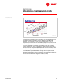
This period describes the components of the absorption refrigeration cycle.
Comparing the absorption refrigeration cycle with the more familiar vaporcompression refrigeration cycle is often an easy way to introduce it. Like the
vapor-compression refrigeration cycle, the absorption refrigeration cycle uses
the principles of heat transfer and change-of-phase of the refrigerant to produce
the refrigeration effect.
Both the vapor-compression and absorption refrigeration cycles accomplish
cooling by absorbing heat from one fluid (chilled water) and transferring it to
another fluid (cooling water or ambient air). Both cycles circulate refrigerant
inside the chiller to transfer this heat from one fluid to the other. Both cycles
also include a device to increase the pressure of the refrigerant and an
expansion device to maintain the internal pressure difference, which is critical
to the overall heat transfer process.
TRG-TRC011-EN
3
period one
Absorption Refrigeration Cycle
notes
reject heat
'
&
condenser
compressor
expansion
device
energy in
$
evaporator
absorb heat
%
Figure 5
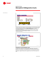
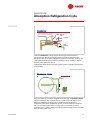
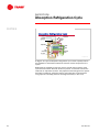
In the vapor-compression refrigeration cycle, refrigerant enters the evaporator
in the form of a cool, low-pressure mixture of liquid and vapor ($). Heat is
transferred from the relatively warm air or water to the refrigerant, causing the
liquid refrigerant to boil. The resulting vapor (%) is then pumped from the
evaporator by the compressor, which increases the pressure and temperature
of the refrigerant vapor.
The hot, high-pressure refrigerant vapor (&) leaving the compressor enters the
condenser where heat is transferred to ambient air or water at a lower
temperature. Inside the condenser, the refrigerant vapor condenses into a
liquid. This liquid refrigerant (') then flows to the expansion device, which
creates a pressure drop that reduces the pressure of the refrigerant to that of
the evaporator. At this low pressure, a small portion of the refrigerant boils (or
flashes), cooling the remaining liquid refrigerant to the desired evaporator
temperature. The cool mixture of liquid and vapor refrigerant ($) travels to the
evaporator to repeat the cycle.
The vapor-compression refrigeration cycle is discussed in detail in the
Refrigeration Cycle clinic.
4
TRG-TRC011-EN
period one
Absorption Refrigeration Cycle
notes
reject heat
&
'
heat energy in
generator
condenser
pump
expansion
device
absorber
evaporator
$
%
absorb heat
reject heat
Figure 6
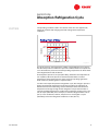
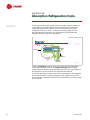
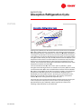
There are two fundamental differences between the absorption refrigeration
cycle and the vapor-compression refrigeration cycle. The first is that the
compressor is replaced by an absorber, pump, and generator. The second is
that, in addition to the refrigerant, the absorption refrigeration cycle uses a
secondary fluid, called the absorbent. The condenser, expansion device, and
evaporator sections, however, are the same.
Refrigerant enters the evaporator in the form of a cool, low-pressure mixture of
liquid and vapor ($). Heat is transferred from the relatively warm water to the
refrigerant, causing the liquid refrigerant to boil. Using an analogy of the vaporcompression cycle, the absorber acts like the suction side of the compressor—it
draws in the refrigerant vapor (%) to mix with the absorbent. The pump acts like
the compression process itself—it pushes the mixture of refrigerant and
absorbent up to the high-pressure side of the system. The generator acts like
the discharge of the compressor—it delivers the refrigerant vapor (&) to the rest
of the system.
The refrigerant vapor (&) leaving the generator enters the condenser, where
heat is transferred to water at a lower temperature, causing the refrigerant
vapor to condense into a liquid. This liquid refrigerant (') then flows to the
expansion device, which creates a pressure drop that reduces the pressure of
the refrigerant to that of the evaporator. The resulting mixture of liquid and
vapor refrigerant ($) travels to the evaporator to repeat the cycle.
The components of the absorption refrigeration cycle will be discussed in detail
in a moment.
TRG-TRC011-EN
5
period one
Absorption Refrigeration Cycle
notes
▲
◆
Stable
◆
Nontoxic
◆
Low cost
◆
Readily available
◆
Environmentally friendly
◆
High latent heat of
vaporization
Figure 7
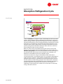
Absorption System Fluids
Probably the greater of these differences between the vapor-compression and
absorption refrigeration cycles, however, is the types of fluids used. The vaporcompression refrigeration cycle generally uses a halocarbon (such as
HCFC-123, HCFC-22, HFC-134a, etc.) as the refrigerant. The particular absorption
refrigeration cycle discussed in this clinic uses distilled water as the
refrigerant.
Distilled water is stable, nontoxic, low in cost, readily available,
environmentally friendly, and has a relatively high heat of vaporization
(1000 Btu/lb [2326 kJ/kg]). The heat of vaporization is the amount of heat
required to fully transform (evaporate) liquid to a vapor at a given pressure.
For the water to be used as a refrigerant, the cycle must operate in a vacuum,
that is, at a pressure below atmospheric pressure. This will be discussed
shortly. Finally, large quantities of water are easily absorbed by the absorbent
and separated within the absorption cycle.
Throughout the remainder of this clinic, when the term refrigerant is used, it
refers to distilled water.
6
TRG-TRC011-EN
period one
Absorption Refrigeration Cycle
notes
▲
◆
High affinity for water
(refrigerant)
◆
In solution, higher
boiling point than water
◆
Nontoxic
Figure 8
Additionally, the absorption refrigerant cycle uses a second fluid called an
absorbent solution. The absorbent solution is confined to the absorber and
generator sections of the cycle, and is used to carry the refrigerant from the
low-pressure side (evaporator) to the high-pressure side (condenser) of the
chiller. For this purpose, the absorbent should have a strong affinity (attraction)
for the refrigerant and, when in solution with the refrigerant, a boiling point that
is substantially higher than that of the refrigerant.
The absorbent commonly used with water (the refrigerant) is lithium bromide.
Lithium bromide, a nontoxic salt, has a high affinity for water. Also, when in
solution with water, the boiling point of lithium bromide is substantially higher
than that of water. This makes it easy to separate the refrigerant from the
absorbent at low pressures. A certain quantity of absorbent solution, therefore,
is pumped from the absorber to the generator in order to transport the
refrigerant.
Another common refrigerant–absorbent pair is ammonia as the refrigerant and
water as the absorbent. These fluids are more common in small residential
applications. There are other refrigerant–absorbent combinations; this clinic,
however, will focus on water as the refrigerant and lithium bromide as the
absorbent.
TRG-TRC011-EN
7
period one
Absorption Refrigeration Cycle
notes
dilute
solution
intermediate
solution
concentrated
solution
Figure 9
These two fluids, the refrigerant and the absorbent, are mixed inside the chiller
in various concentrations. The term dilute solution refers to a mixture that
has a relatively high refrigerant content and low absorbent content. A
concentrated solution has a relatively low refrigerant content and high
absorbent content. An intermediate solution is a mixture of dilute and
concentrated solutions.
steam or
hot water
generator
evaporator
condenser
cooling
water
chilled
water
heat
exchanger
absorber
Figure 10
Components of the Absorption Cycle
The four basic components of the absorption refrigeration cycle are the
generator and condenser on the high-pressure side, and the evaporator and
absorber on the low-pressure side. The pressure on the high-pressure side of
the system is approximately ten times greater than that on the low-pressure
side.
8
TRG-TRC011-EN
period one
Absorption Refrigeration Cycle
notes
The operating conditions used in this section of the clinic are approximate,
subject to variation with changing load and cooling-water temperature
conditions.
temperature
115°F
[46.1°C]
45°F
[7.2°C]
0.15 psia
1.5 psia
[1.034 kPa]
kPa]
[10.34 kPa]
kPa]
pressure
Figure 11
At a given pressure, the temperature at which a liquid will boil into a vapor is
the same temperature at which the vapor will condense back into a liquid. This
curve illustrates the pressures and corresponding temperatures at which water
(the refrigerant) boils and condenses.
At atmospheric pressure (14.7 psia [101.3 kPa]), water boils and evaporates at
212 °F [100 °C]. When the pressure is decreased, water boils at a lower
temperature. At the lower pressure, there is less force pushing against the
water molecules, allowing them to separate easier.
Just like in the vapor-compression refrigeration cycle, this change in pressure
allows the evaporator temperature to be low enough for the refrigerant to
absorb heat from the water being cooled. Likewise, it allows the condenser
temperature to be high enough for the refrigerant to reject heat to water at
normally available temperatures. Inside of the evaporator, the pressure is very
low, 0.15 psia [1.034 kPa] in this example, so that the refrigerant boils at 45ºF
[7.2ºC]. In the condenser, however, the pressure is much higher (1.5 psia
[10.34 kPa]) so that the refrigerant condenses at 115ºF [46.1ºC].
TRG-TRC011-EN
9
period one
Absorption Refrigeration Cycle
notes
steam or
hot water
refrigerant
vapor
generator
concentrated
solution
dilute
solution
Figure 12
Starting on the high-pressure side of the cycle, the purpose of the generator is
to deliver the refrigerant vapor to the rest of the system. It accomplishes this by
separating the water (refrigerant) from the lithium bromide-and-water solution.
In the generator, a high-temperature energy source, typically steam or hot
water, flows through tubes that are immersed in a dilute solution of refrigerant
and absorbent. The solution absorbs heat from the warmer steam or water,
causing the refrigerant to boil (vaporize) and separate from the absorbent
solution. As the refrigerant is boiled away, or “generated,” the absorbent
solution becomes more concentrated.
The concentrated absorbent solution returns to the absorber and the refrigerant
vapor migrates to the cooler condenser. Physically, the generator and
condenser are contained inside of the same shell. The pressure in the
condenser section is less than the pressure in the generator section. This is
because the temperature of the cooling water flowing through the tubes of the
condenser is less than the temperature of the steam or hot water flowing
through the tubes of the generator.
10
TRG-TRC011-EN
period one
Absorption Refrigeration Cycle
notes
refrigerant
vapor
condenser
cooling
water
liquid
refrigerant
Figure 13
Inside the condenser, cooling water flows through tubes and the hot
refrigerant vapor fills the surrounding space. As heat transfers from the
refrigerant vapor to the water, refrigerant condenses on the tube surfaces. The
condensed liquid refrigerant collects in the bottom of the condenser before
traveling to the expansion device.
In absorption water chillers, the cooling water system is typically connected to a
cooling tower.
evaporator
liquid
refrigerant
expansion
device
Figure 14
From the condenser, the liquid refrigerant flows through an expansion device
into the evaporator. The expansion device is used to maintain the pressure
difference between the high-pressure (condenser) and low-pressure
(evaporator) sides of the refrigeration system. In this example, the expansion
device is a throttling pipe, which is a long section of pipe with an orifice
restriction in it. It creates a liquid seal that separates the high-pressure and lowpressure sides of the cycle.
TRG-TRC011-EN
11
period one
Absorption Refrigeration Cycle
notes
As the high-pressure liquid refrigerant flows through the expansion device, it
causes a pressure drop that reduces the refrigerant pressure to that of the
evaporator. This pressure reduction causes a small portion of the liquid
refrigerant to boil off, or “flash,” cooling the remaining refrigerant to the
desired evaporator temperature. The cooled mixture of liquid and vapor
refrigerant then flows into the evaporator pan.
refrigerant
vapor
chilled
water
evaporator
absorber
liquid
refrigerant
evaporator
spray pump
Figure 15
Inside the evaporator, relatively warm return water from the chilled-water
system flows through the tubes. An evaporator pump draws the liquid
refrigerant from the bottom of the evaporator and continuously circulates it to
be sprayed over the tube surfaces. This maximizes heat transfer.
As heat transfers from the water to the cooler liquid refrigerant, the refrigerant
boils (vaporizes) and the resulting refrigerant vapor is drawn into the lowerpressure absorber. Physically, the evaporator and absorber are contained inside
the same shell.
12
TRG-TRC011-EN
period one
Absorption Refrigeration Cycle
notes
refrigerant
vapor
absorber
intermediate
solution
concentrated
solution
absorber
spray pump
cooling
water
dilute
solution
Figure 16
Inside the absorber, the refrigerant vapor is absorbed by the lithium bromide
solution. As the refrigerant vapor is absorbed, it condenses from a vapor to a
liquid, releasing the heat it acquired in the evaporator. This heat, along with the
heat generated during the process of being absorbed, is rejected to the cooling
water that is circulated through the absorber tube bundle. Absorption of the
refrigerant vapor creates a low pressure area within the absorber. This lower
pressure, along with the absorbent’s affinity for water, induces a continuous
flow of refrigerant vapor from the evaporator.
Maximum surface area is provided by spraying the solution over the tube
bundle. This also provides maximum heat transfer to the cooling water. The
absorber spray pump mixes concentrated absorbent solution (returning from
the generator) with dilute solution (from the bottom of the absorber) and
delivers this intermediate solution to the absorber sprays.
There are two reasons for using an intermediate solution rather than a
concentrated solution in the absorber sprays. First, for effective tube wetting, a
greater quantity of solution is required than is available from the generator.
Therefore, dilute solution is mixed with the concentrated solution to increase
the total quantity of solution being sprayed over the tube surfaces. Second, if
concentrated solution were sprayed directly upon the absorber tube bundle, it
would be subjected to temperatures that could cause it to crystallize—a
solidification of the bromide salt. Therefore, the concentration is reduced by
mixing it with dilute solution.
TRG-TRC011-EN
13
period one
Absorption Refrigeration Cycle
notes
concentrated
solution
heat
exchanger
dilute
solution
generator pump
Figure 17
As the lithium bromide solution absorbs the refrigerant, it becomes diluted and
has less ability to absorb water vapor. To complete the cycle and sustain
operation, the absorbent solution must be reconcentrated. Consequently, the
generator pump continuously returns the dilute solution to the generator to
again separate the refrigerant vapor from the solution and reconcentrate the
solution, thus repeating the cycle.
This cool dilute solution that is pumped from the absorber to the generator, and
the hot concentrated solution returning from the generator, pass through a
heat exchanger. This transfer of heat preheats the dilute solution, reducing the
heat energy required to boil the refrigerant within the generator, and also
precools the concentrated solution, reducing the required flow rate of cooling
water through the absorber.
Notice that in this example cycle, the cooling water passes through the
condenser after passing through the absorber. Some absorption chiller designs
split the cooling water and deliver it directly to both the absorber and the
condenser.
14
TRG-TRC011-EN
period one
Absorption Refrigeration Cycle
notes
15 psia
re
ssu 5 psia
pre
r
o
[34.5 kPa]
kPa]
va p
50
55
60
65
concentration
40
[103.4 kPa]
kPa]
1 psia
[6.9 kPa]
kPa]
$
&
0.1 psia
%
[0.69 kPa]
kPa]
50°F
100°F
150°F
200°F
[10°C]
[37.8°C]
[65.6°C]
[93.3°C]
solution temperature
LiBr solution
Figure 18
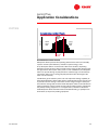
Equilibrium Chart
The performance of the absorption refrigeration cycle can be analyzed using a
special chart called an Equilibrium Chart for Aqueous Lithium Bromide
Solutions. This chart plots the vapor pressure (vertical axis) versus the
temperature (horizontal axis) and concentration (diagonal lines) of the lithium
bromide (LiBr) solution.
The chart shows that an increase in concentration ($ to %), at a constant
solution temperature, results in a decrease in vapor pressure. Conversely, a
decrease in solution temperature ($ to &), at a constant concentration, results
in a decrease in vapor pressure. Assuming that no air or other
noncondensables are inside the chiller, the vapor pressure of the solution
determines the temperature at which the refrigerant will vaporize. In other
words, the combination of solution temperature and concentration determines
the temperature at which the refrigerant will boil (vaporize).
TRG-TRC011-EN
15
period one
Absorption Refrigeration Cycle
notes
steam or
hot water
generator
condenser
cooling
water
'
evaporator
&
chilled
water
%
heat
exchanger
absorber
(
)
$
expansion
device
Figure 19
A diagram of a typical absorption refrigeration cycle can be superimposed on
this equilibrium chart to demonstrate the function of each component in the
system.
Realize that the equilibrium chart can only be used for those portions of the
cycle where the lithium bromide solution is present. It cannot be used for the
condenser or evaporator sections. The properties of the refrigerant as it passes
through the condenser, expansion device, and evaporator can be analyzed
using a pressure–enthalpy chart for the refrigerant (water, in this case).
16
TRG-TRC011-EN
period one
Absorption Refrigeration Cycle
notes
15 psia
re
ssu 5 psia
pre
r
o
[34.5 kPa]
kPa]
va p
1 psia
[6.9 kPa]
kPa]
50
55
%
1.5 psia
[10.3 kPa]
kPa]
$
0.1 psia
[0.69 kPa]
kPa]
)
60
65
&
concentration
40
[103.4 kPa]
kPa]
'
(
50°F
100°F
150°F
200°F
[10°C]
[37.8°C]
[65.6°C]
[93.3°C]
solution temperature
LiBr solution
Figure 20
Starting at the absorber, the dilute lithium bromide solution leaves the absorber
($) at 105°F [40.6ºC] and 59% concentration. This solution passes through the
heat exchanger, where it is preheated to 175°F [79.4°C] (%). (Notice that there is
no change in concentration as the solution passes through the heat exchanger.)
In the generator, the solution absorbs heat from the steam or hot water flowing
through the tubes. Initially, this only sensibly heats the solution to &, that is, the
temperature of the solution increases while the concentration stays the same.
At this point, the refrigerant begins to boil (vaporize) and separate from the
solution. This increases the concentration of the lithium bromide solution as the
temperature continues to increase (').
The concentrated solution ('), now at 215°F [101.7ºC] and 64.5%, passes
through the heat exchanger where it is cooled to 135°F [57.2ºC] ((). This cooled,
concentrated solution (() is then mixed with dilute solution from the absorber
($), and this intermediate solution ()) (118°F [47.8ºC] and 62% concentration) is
pumped to the absorber spray trees. In the absorber, refrigerant vapor is
absorbed by the intermediate solution, decreasing its concentration to 59%,
while heat is transferred to the cooling water. The resulting cooled, dilute
solution ($) returns to the generator to repeat the cycle.
This chart also can be used to demonstrate the operating pressures of the cycle.
In this example, the low-pressure sections of the cycle are operating at
approximately 0.15 psia [1.034 kPa], and the high-pressure sections are
operating at approximately 1.5 psia [10.34 kPa].
TRG-TRC011-EN
17
period two
Absorption Chiller Types
notes
period two
Figure 21
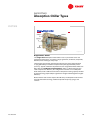
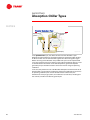
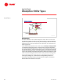
Lithium bromide-and-water absorption chillers are classified by the firing
method—that is, how the primary generator is heated and whether it has a
single- or a multiple-effect generator. Indirect-fired chillers are heated with
steam or a hot liquid (such as water) that is typically supplied by an on-site
boiler or a local utility. It can also be heated by waste energy that is recovered
from the exhaust of a gas turbine or by some other heat recovery device. Directfired chillers are heated via the combustion of fossil fuels. An absorption chiller
with a single generator is called a single-effect chiller. Multiple-effect chillers
have multiple generators.
Like vapor-compression water chillers, absorption chillers can also be classified
by the condensing method employed, either air-cooled or water-cooled.
Physical size limitations typically constrain air-cooled condensing to ammoniaand-water absorption equipment that is applied in residential and small
commercial applications (3 to 5 tons [10 to18 kW]). Most large commercial
(20 to 1,500 tons [70 to 5,300 kW]) water-and-lithium bromide absorption
chillers employ water-cooled condensing with cooling towers, because of the
higher energy efficiency at design conditions.
18
TRG-TRC011-EN
period two
Absorption Chiller Types
notes
condenser
generator
evaporator
absorber
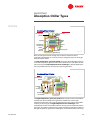
Figure 22
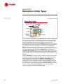
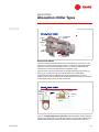
Single-Effect Chiller
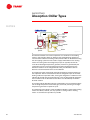
The single-effect absorption water chiller uses a cycle similar to the one
presented in Period One. It includes a single generator, condenser, evaporator,
absorber, heat exchanger, and pumps.
These chillers are typically operated on low-pressure steam (approximately
15 psig [204.8 kPa]) or medium-temperature liquids (approximately 270°F
[132.2°C]). Typical coefficients of performance for single-effect water chillers are
0.6 to 0.8. The coefficient of performance (COP) is a dimensionless ratio
used to express the efficiency of a refrigeration machine. For an absorption
water chiller, COP is defined as the ratio of evaporator cooling capacity divided
by the heat energy required by the generator. A higher COP designates a higher
efficiency.
Notice that the COP used to express the efficiency of absorption water chillers
excludes the electrical energy needed to operate the pumps, purge, and
controls.
TRG-TRC011-EN
19
period two
Absorption Chiller Types
notes
steam or
hot water
generator
condenser
cooling
water
evaporator
heat
exchanger
absorber
absorber
spray pump
chilled
water
expansion
device
evaporator spray pump
generator pump
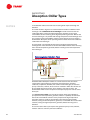
Figure 23
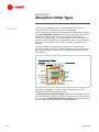
Let us review Period One briefly. In the generator, dilute solution absorbs heat
from the steam or hot water, causing the refrigerant to boil and separate from
the absorbent solution. As the refrigerant boils away, the absorbent solution
becomes concentrated and returns to the absorber. The resulting hot
refrigerant vapor migrates to the cooler condenser, where heat transfers from
the refrigerant vapor to the cooling water, causing the refrigerant to condense.
The resulting condensed liquid refrigerant flows through an expansion
device, causing a pressure drop that reduces the refrigerant pressure and
temperature to the desired evaporator conditions. The cooled mixture of liquid
and vapor refrigerant then flows into the evaporator pan, from which the
evaporator spray pump continuously pumps the liquid refrigerant and sprays
it over the tubes. As heat transfers from the water to the cooler refrigerant, the
refrigerant boils (vaporizes) and the resulting refrigerant vapor is drawn into the
absorber.
Inside the absorber, the refrigerant vapor is absorbed by the lithium bromide
solution. As the refrigerant vapor is absorbed, it is also condensed, thereby
releasing heat to the cooling water. The absorber spray pump mixes
concentrated absorbent solution (returning from the generator) with dilute
solution (from inside the absorber) and delivers this intermediate solution to
the absorber sprays. To complete the cycle, the generator pump returns the
dilute absorbent solution to the generator to be reconcentrated. This cool dilute
solution passes through a heat exchanger to be preheated by the hot
concentrated solution returning from the generator.
20
TRG-TRC011-EN
period two
Absorption Chiller Types
notes
lowlow-temperature
generator
highhigh-temperature
generator
condenser
evaporator
absorber
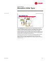
Figure 24
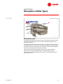
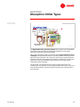
Double-Effect Chiller
The double-effect absorption chiller includes the same basic components as the
single-effect chiller; however, it also includes an additional generator, heat
exchanger, and pump.
The high-temperature generator can use steam or hot water (indirect-fired) as
the energy source, or it can use the combustion of a fuel such as natural gas or
oil (direct-fired). First we will discuss an indirect-fired, double-effect absorption
chiller. The direct-fired chiller will be discussed later.
Indirect-fired, double-effect absorption chillers are typically operated on
medium-pressure steam (approximately 115 psig [894.3 kPa]) or hightemperature liquids (approximately 370°F [187.8 °C]). Typical COPs for these
chillers are 0.9 to 1.2.
TRG-TRC011-EN
21
period two
Absorption Chiller Types
notes
refrigerant
vapor
highhigh-temperature
generator
steam or
hot water
condensed
refrigerant
refrigerant
vapor
to absorber
lowlow-temperature
generator
condenser
Figure 25
In the high-temperature generator, very high temperature steam or hot
water flows through tubes that are immersed in an absorbent solution that is at
an intermediate concentration. The solution absorbs heat from the warmer
steam or water, causing the refrigerant to boil and separate from the absorbent
solution. As the refrigerant boils away, the absorbent solution becomes
concentrated and returns to the absorber.
The hot refrigerant vapor produced in the high-temperature generator migrates
to the low-temperature generator, where it flows through tubes that are
immersed in a dilute solution. The solution absorbs heat from the hightemperature refrigerant vapor, causing the refrigerant in the low-temperature
generator to boil and separate from the absorbent solution. As that refrigerant
boils away, the concentration of the absorbent solution increases and it returns
to the absorber.
The low-temperature refrigerant vapor produced in the low-temperature
generator migrates to the cooler condenser. Additionally, the liquid refrigerant
that condensed inside the tubes of the low-temperature generator also flows
into the condenser.
22
TRG-TRC011-EN
period two
Absorption Chiller Types
notes
lowlow-temperature
generator
cooling
water
evaporator
condenser
chilled
water
lowlow-temperature
heat exchanger
expansion
device
absorber
absorber
spray pump
evaporator spray pump
lowlow-temperature
generator pump
Figure 26
Next, the refrigerant travels through the condenser, expansion device,
evaporator and absorber in a manner similar to refrigerant travel in the singleeffect absorption chiller.
The low-temperature generator pump returns the dilute absorbent solution
to the low-temperature generator to be reconcentrated. This cool dilute solution
passes through the low-temperature heat exchanger to be preheated by the
hot concentrated solution returning from the two generators.
steamsteam-fired
highhigh-temperature
generator
highhigh-temperature
generator
pump
condensate
heat
exchanger
highhigh-temperature
heat exchanger
Figure 27
The high-temperature generator pump draws a portion of the intermediate
solution from the low-temperature generator and delivers it to the hightemperature generator to be reconcentrated. Some of this cooler intermediate
solution passes through the high-temperature heat exchanger to be
preheated by the hot concentrated solution coming from the high-temperature
generator. This reduces the heat energy required to boil the refrigerant inside of
the high-temperature generator. Precooling the concentrated solution returning
TRG-TRC011-EN
23
period two
Absorption Chiller Types
notes
to the absorber reduces the flow rate of cooling water required through the
absorber.
The chiller shown in Figure 27 is steam-fired and includes an additional heat
exchanger. This condensate heat exchanger transfers heat from the hot
condensed steam, leaving the high-temperature generator, to the cooler
intermediate solution returning to the high-temperature generator. Notice that
this heat exchanger is in parallel with the high-temperature heat exchanger and
only a portion of the intermediate solution passes through each one. Again, a
double-effect absorption chiller operating with hot water would not include the
condensate heat exchanger.
The precooled, concentrated solution leaving the high-temperature heat
exchanger then mixes with the rest of the intermediate solution that is returning
from the low-temperature generator, before traveling to the low-temperature
heat exchanger.
lowlow-temperature
generator
highhigh-temperature
generator
highhigh-temperature
generator pump
absorber
lowlow-temperature generator pump
Figure 28
All double-effect absorption chillers are constructed from the same basic
components: high-temperature generator, low-temperature generator,
condenser, evaporator, absorber, two solution heat exchangers, and several
pumps. There are, however, three common methods in which the solution can
be circulated through the chiller: series, parallel, and reverse-series. The
double-effect chiller used in the previous example employs the reverse-series
flow cycle.
In a reverse-series flow cycle, the dilute solution leaving the absorber is
pumped to the low-temperature generator, where it is partially concentrated.
Part of this intermediate solution is then pumped to the high-temperature
generator, where it is further concentrated. The remaining intermediate
solution, leaving the low-temperature generator, is mixed with the concentrated
solution, leaving the high-temperature generator, before returning to the
absorber.
The reverse-series flow cycle requires two generator pumps. This, however,
makes it easier to control in part-load conditions.
24
TRG-TRC011-EN
period two
Absorption Chiller Types
notes
lowlow-temperature
generator
highhigh-temperature
generator
absorber
generator pump
Figure 29
In the series flow cycle, the dilute solution from the absorber is pumped
entirely to the high-temperature generator. As the refrigerant boils away and
migrates to the low-temperature generator, the absorbent solution becomes
concentrated. The resulting intermediate solution then flows to the lowtemperature generator, where it is further concentrated by the refrigerant vapor
that was created in the high-temperature generator. The concentrated solution
then flows back to the absorber to repeat the cycle.
The series flow cycle has been the mainstay of most double-effect absorption
chiller designs for many years. It is simple because it requires only one
generator pump and is fairly straightforward to control. The series cycle,
however, requires a significantly larger heat exchanger to obtain similar COPs
to the other cycles.
TRG-TRC011-EN
25
period two
Absorption Chiller Types
notes
lowlow-temperature
generator
highhigh-temperature
generator
absorber
generator pump
Figure 30
In the parallel flow cycle, the dilute solution from the absorber is split
between the low-temperature and high-temperature generators. Both streams
of dilute solution are concentrated in the generators and mix together again
before returning to the absorber. The parallel flow cycle can be implemented
using one generator pump (as shown in Figure 30) if a throttling device is used
to control the flow of solution to the low-temperature generator. Separate
generator pumps should be used for control over the full range of operating
conditions.
In the end, the performance of a double-effect absorption chiller has little to do
with the flow cycle employed. Instead, the performance depends on the choice
of operating conditions, the amount of heat transfer surface area, the
effectiveness of the purge system, the materials of construction, the design of
the controls, and the manufacturing techniques.
26
TRG-TRC011-EN
period two
Absorption Chiller Types
notes
lowlow-temperature
generator
condenser
evaporator
absorber
highhigh-temperature
generator
Figure 31
Direct-Fired Chiller
The indirect-fired absorption chillers discussed previously use steam or a hot
liquid (such as water) as the energy source. In contrast, the high-temperature
generator of a direct-fired absorption chiller uses the heat released by the
combustion of a fossil fuel to boil off the refrigerant vapor.
Common fuels used to fire the burner in the high-temperature generator are
natural gas, number 2 fuel oil, or liquid petroleum (LP). Additionally,
combination burners are available that can be switched from one fuel to
another. Typical COPs for direct-fired, double-effect chillers are 0.9 to 1.1 (based
on the higher heating value, or HHV, of the fuel).
highhightemperature
generator
refrigerant vapor
refrigerant
vapor
condensed
refrigerant
condenser
lowlow-temperature
generator
Figure 32
The example direct-fired chiller shown here employs the reverse-series flow
cycle. In the high-temperature generator, the intermediate solution absorbs
heat that is generated by the combustion process. Similar to the indirect-fired,
double-effect chiller, this transfer of heat causes the refrigerant to boil and
TRG-TRC011-EN
27
period two
Absorption Chiller Types
notes
separate from the absorbent solution. As the refrigerant boils away, the
solution becomes concentrated and returns to the absorber.
The hot refrigerant vapor produced in the high-temperature generator migrates
to the low-temperature generator where it flows through the tubes that are
immersed in a dilute solution. The solution absorbs heat from the hightemperature refrigerant vapor, causing the refrigerant in the low-temperature
generator to boil and separate from the absorbent solution. As that refrigerant
boils away, the concentration of the solution increases and it returns to the
absorber.
The low-temperature refrigerant vapor produced in the low-temperature
generator migrates to the cooler condenser. Additionally, the liquid refrigerant
that condensed inside the tubes of the low-temperature generator flows into
the condenser.
condenser
lowlow-temperature
generator
evaporator
lowlow-temperature
heat exchanger
absorber
absorber
spray pump
cooling
water
chilled
water
expansion
device
evaporator spray pump
lowlow-temperature
generator pump
Figure 33
Next, the refrigerant travels through the condenser, expansion device,
evaporator, and absorber in a manner similar to refrigerant travel in the
indirect-fired double-effect absorption chiller.
The low-temperature generator pump returns the dilute absorbent solution
to the low-temperature generator to be reconcentrated. This cool dilute solution
passes through the low-temperature heat exchanger to be preheated by the
hot concentrated solution returning from the two generators.
28
TRG-TRC011-EN
period two
Absorption Chiller Types
notes
highhigh-temperature
generator
highhigh-temperature
generator
pump
highhigh-temperature
heat exchanger
Figure 34
The high-temperature generator pump draws a portion of the intermediate
solution from the low-temperature generator and delivers it to the hightemperature generator to be reconcentrated.
This cooler intermediate solution passes through the high-temperature heat
exchanger to be preheated by the hot concentrated solution returning from the
high-temperature generator. This reduces the heat energy required to boil the
refrigerant inside the high-temperature generator. Precooling the concentrated
solution returning to the absorber reduces the flow rate of cooling water
required through the absorber.
The precooled, concentrated solution leaving the high-temperature heat
exchanger then mixes with the rest of the intermediate solution that is returning
from the low-temperature generator, before traveling to the low-temperature
heat exchanger.
TRG-TRC011-EN
29
period two
Absorption Chiller Types
notes
refrigerant
vapor
hot
water
auxiliary
heating bundle
highhigh-temperature
generator
Figure 35
Chiller/Heater
One of the benefits of a direct-fired absorption chiller is that it can be used to
provide both cooling and heating. These chillers, therefore, can be installed in
systems to supplement, or even replace, primary heating or domestic hot water
equipment. This can free up equipment-room space that was required for this
heating equipment.
In the direct-fired absorption chiller shown here, an auxiliary heating bundle
can be added, allowing the chiller to make hot water as well as chilled water.
The auxiliary heating bundle draws in a portion of the refrigerant vapor leaving
the high-temperature generator. Water flowing through the tubes absorbs heat
from this hot refrigerant vapor, causing the refrigerant to condense on the tube
surfaces. This transfer of heat warms the water to a temperature where it can be
used for comfort heating, domestic hot water needs, or process heating loads.
The key advantage of this design is that it can be configured to operate in
cooling only, heating only, or simultaneous cooling/heating modes. For
simultaneous operation, however, two separate sets of pipes are needed to
deliver chilled and hot water to the system.
30
TRG-TRC011-EN
period two
Absorption Chiller Types
notes
▲
▲
▲
▲
Figure 36
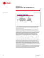
Each of these operating modes serves a different load requirement.
n In cooling only mode, the absorption chiller operates exactly like the
standard chiller offering. Its function is to make cold water.
n In heating only mode, the only function of the chiller is to make hot water.
n In simultaneous cooling/heating – cooling priority mode, the primary
function of the chiller is to make cold water. The heating function is
secondary and will be performed only if there is excess capacity (burner
fire).
n In simultaneous heating/cooling – heating priority mode, the primary
function of the chiller is to make hot water. The cooling function is
secondary and will be performed only if there is excess capacity (burner
fire).
When providing cooling, this type of direct-fired absorption chiller can only
supply a limited amount of heat, dependent on the current cooling load. If the
heating and cooling loads for a particular application are substantial and
simultaneous, it may be best to use this chiller to supplement, instead of
replace, the main heating equipment.
TRG-TRC011-EN
31
period two
Absorption Chiller Types
notes
changeover
valve
refrigerant
vapor
hot
water
evaporator
high-temperature
generator
absorber
Figure 37
An alternate method is to use the evaporator as a condenser in the heating
mode. In this example chiller, by switching the cooling/heating changeover
valve the chiller switches to heating mode, and hot water can be delivered using
the same piping system that was used to supply chilled water in the cooling
mode. The cooling tower and refrigerant pumps can typically be shut off.
In the direct-fired high-temperature generator, heat that is generated by the
combustion process causes the refrigerant to boil and separate from the
absorbent solution. As the refrigerant boils away, the absorbent solution
becomes concentrated and returns to the absorber.
The refrigerant vapor produced by the high-temperature generator flows into
the evaporator. Heat is transferred from the hot refrigerant vapor to the water
flowing inside the evaporator tubes, causing the refrigerant to condense on the
tube bundle and fall into the evaporator pan. This condensed liquid refrigerant
then overflows into the absorber section where it is absorbed by the lithium
bromide solution.
The resulting dilute absorbent solution is preheated as it is pumped through the
low- and high-temperature heat exchangers, eventually returning to the hightemperature generator to repeat the cycle.
The advantage of this design is that no additional bundle is required for heating
mode. This chiller, however, can only operate in cooling mode or heating
mode—no simultaneous operation is possible.
32
TRG-TRC011-EN
period two
Absorption Chiller Types
notes
▲
▲
◆
Problems with solution stability
◆
Increased risk of corrosion problems
◆
More expensive pressure vessel design requirements
◆
Greater first cost due to added components
◆
Larger physical size
Figure 38
While they are presently not available, higher-effect absorption chillers are
being studied for commercial use due their potential for higher COPs. Typical
COPs for these triple-effect cycles are 1.4 to 1.5. Implementation of these cycles
into commercial water chillers, however, includes difficulties such as the
following.
n Higher solution temperatures create problems with stability of the
absorbent solution and performance additives, as well as additional
material corrosion problems.
n In some cases, higher operating pressures which require high-cost pressure
vessel designs.
n Greater first cost due to the need for additional pumps and heat exchangers.
n Larger physical size.
As mentioned earlier, other cycles and fluid combinations are also being
studied for commercial use. The focus of this clinic, however, is limited to water
chillers that use a lithium bromide-and-water solution.
TRG-TRC011-EN
33
period three
Capacity Control
notes
period three
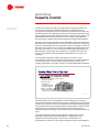
Figure 39
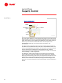
The primary objective of the chiller capacity control system is to reliably
maintain the temperature of the chilled water leaving the evaporator. The
control system monitors the temperature of the leaving chilled water, compares
it to the setpoint, and adjusts the amount of solution supplied to the generator
and the heat input to the generator.
or
va p
re
s su
pre
40
50
55
5 psia
[34.5 kPa]
kPa]
60
65
concentration
15 psia
[103.4 kPa]
kPa]
1 psia
[6.9 kPa]
kPa]
$
&
0.1 psia
%
[0.69 kPa]
kPa]
50°F
100°F
150°F
200°F
[10°C]
[37.8°C]
[65.6°C]
[93.3°C]
solution temperature
LiBr solution
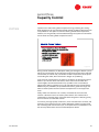
Figure 40
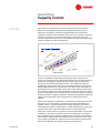
In Period One, the Equilibrium Chart for Aqueous Lithium Bromide Solutions
was introduced to explain how the combination of solution temperature and
concentration determines the pressure, and temperature, at which the
refrigerant will boil (vaporize) in the evaporator. Recall that an increase in
solution concentration ($ to %), at a constant temperature, results in a decrease
in vapor pressure. Conversely, a decrease in solution temperature ($ to &), at a
constant concentration, results in a decrease in vapor pressure. Assuming that
no air or other noncondensables are inside the chiller, the vapor pressure of the
solution determines the temperature at which the refrigerant will vaporize. In
34
TRG-TRC011-EN
period three
Capacity Control
notes
other words, the combination of solution temperature and concentration
determines the temperature at which the refrigerant will boil (vaporize).
Varying the temperature at which the refrigerant boils in the evaporator
changes the capacity of the absorption water chiller. So, in order to control the
capacity of the chiller to meet the ever-changing system loads, either the
solution temperature or the solution concentration must be varied. Many chiller
control strategies vary both simultaneously.
15 psia
re
ssu 5 psia
pre
r
o
[34.5 kPa]
kPa]
va p
50
55
1 psia
%
[6.9 kPa]
kPa]
0.1 psia
$
$ )
[0.69 kPa]
kPa]
&
60
65
concentration
40
[103.4 kPa]
kPa]
'
(
50°F
100°F
150°F
200°F
[10°C]
[37.8°C]
[65.6°C]
[93.3°C]
solution temperature
LiBr solution
Figure 41
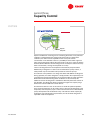
A common method used to vary the temperature of the solution is to vary the
amount of absorbent solution delivered to the generator. At part load, in
response to a changing leaving-chilled-water temperature, less dilute solution is
pumped to the generator, reducing the heat energy required to boil off the
refrigerant vapor. Reduced heat input results in less refrigerant boiled off
(vaporized) in the generator and a less-concentrated solution returning to the
absorber (', 56% shown here at part load versus 64.5% at full load shown in
Figure 20). This less-concentrated solution has a lower affinity for water vapor
and, therefore, the pressure inside the absorber–evaporator sections increases
(pressures at $ and )). This increased pressure causes the refrigerant inside the
evaporator to boil at a higher temperature, reducing the temperature difference
between the chilled water and the refrigerant, thus reducing the chiller’s
capacity.
Because less refrigerant is boiled off in the generator, the refrigerant flow rate
through the cycle is decreased. Consequently, the heat rejected within the
absorber is less. Less heat rejected by the cooling tower typically results in
lower-temperature water returning from the tower, which tends to increase the
capacity of the chiller and further reduces heat input to the generator.
Varying the solution flow to the generator can be accomplished in several ways.
Historically, it has been common to use either a throttling valve or a bypass
valve. A throttling valve creates an additional flow restriction in the pipe from
the absorber to the generator, allowing the solution pump to ride up its pump
curve, reducing the flow rate. A bypass valve diverts a portion of the solution
back into the absorber, thus reducing the flow to the generator.
TRG-TRC011-EN
35
period three
Capacity Control
notes
adjustableadjustablefrequency
drive
absorber
spray pump
generator pump
Figure 42
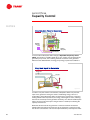
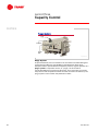
In more modern absorption chiller designs, adjustable-frequency drives
(AFD), also known as variable-speed drives, are used to vary the speed of the
generator pump motor, thus reducing the flow of solution to the generator.
AFDs have the added benefit of saving pump energy at part-load conditions.
energy valve
generator
Figure 43
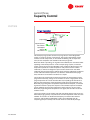
In order to vary the solution concentration, absorption chillers vary the heat
input to the generator. This figure shows a modulating energy valve on a
single-effect, steam absorption chiller. At part load, in response to a changing
leaving-chilled-water temperature, the energy valve begins to close, reducing
the amount of heat input to the generator. Similarly, on a direct-fired absorption
chiller, the amount of heat input to the generator is varied by modulating the
capacity of the burner.
While the solution flow to the generator is varied to maintain the desired
chilled-water temperature, the heat input to the generator is varied to control
the solution concentration. This assures optimal efficiency and keeps the chiller
36
TRG-TRC011-EN
period three
Capacity Control
notes
out of the condition called crystallization—a solidification of the bromide salt.
Crystallization will be discussed next.
In the past, absorption water chillers would vary the heat input to the generator
as the primary means of maintaining the desired leaving-chilled-water
temperature. Because the absorption refrigeration cycle has the capability to
store energy, using the energy valve as the sole method of control would cause
the chiller to react very slowly to a change in capacity. By varying the flow rate
of solution to the generator and absorber sprays, especially with the use of
adjustable-frequency drives, recent chiller designs are now able to react very
quickly to ever-changing load and cooling-water conditions.
40
e
sur 5 psia
res
p
r
o
[34.5 kPa]
kPa]
va p
50
55
60
65
concentration
15 psia
[103.4 kPa]
kPa]
1 psia
[6.9 kPa]
kPa]
crystallization
line
0.1 psia
[0.69 kPa]
kPa]
123°F
[50.6°C]
50°F
100°F
150°F
200°F
[10°C]
[37.8°C]
[65.6°C]
[93.3°C]
solution temperature
LiBr solution
Figure 44
Crystallization
Lithium bromide is chemically classified as a salt. In its solid state, it has a
crystalline structure and, like most salts, is soluble in water. With any salt
solution, there is a “saturation” temperature for a given concentration, below
which the salt begins to leave the solution as a solid. This is called
crystallization.
The saturation temperature for various solution concentrations is represented
by the crystallization line on the equilibrium chart. For example, consider a
lithium bromide solution of 65% concentration. Above 123°F [50.6°C], all salt
remains dissolved in the solution. If, however, the solution concentration
remains the same and the temperature falls below 123°F [50.6°C], the solution
becomes saturated—meaning that the solution contains more salt than it can
hold at that temperature—and the salt begins to leave the solution in a solid
crystalline form.
TRG-TRC011-EN
37
period three
Capacity Control
notes
15 psia
re
ssu 5 psia
pre
r
o
[34.5 kPa]
kPa]
va p
50
55
%
1 psia
[6.9 kPa]
kPa]
$
0.1 psia
[0.69 kPa]
kPa]
)
(
60
65
&
concentration
40
[103.4 kPa]
kPa]
'
crystallization
line
50°F
100°F
150°F
200°F
[10°C]
[37.8°C]
[65.6°C]
[93.3°C]
solution temperature
LiBr solution
Figure 45
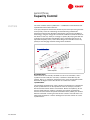
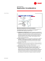
By plotting the single-effect absorption refrigeration cycle on the equilibrium
chart, it is apparent that crystallization is most likely to occur in the heat
exchanger. At this particular condition, the 65% concentrated solution (') is
cooled to 135°F [57.2°C] (() as it passes through the heat exchanger. As noted
previously, the saturation temperature of 65% solution is 123°F [50.6°C] so
there is no danger of crystallization.
Consider, however, if the solution was instead 66% concentrated and cooled to
the same 135°F [57.2°C] temperature. The saturation temperature for 66%
concentrated solution is approximately 143°F [61.7°C]. The result would be a
deposit of salt crystals inside the heat exchanger. Prolonged operation at this
condition could result in a buildup of salt that would eventually block the
passages through the heat exchanger, interrupting the operation of the chiller.
Once a chiller is crystallized, operation can only be resumed after the solution
temperature is raised above its saturation temperature, above 143°F [61.7°C] in
this example. At this higher temperature, the salt crystals would return to the
solution, allowing the chiller to operate again.
With the advent of microelectronic controls, modern absorption water chillers
are designed to monitor and control solution concentrations and temperatures,
allowing the chiller to operate over a broad range of conditions without danger
of crystallization. In addition, safety controls are available to avoid
crystallization and even to de-crystallize the chiller if necessary. Therefore,
crystallization is not the serious problem that it once was with absorption
chillers.
38
TRG-TRC011-EN
period three
Capacity Control
notes
▲
▲
▲
Figure 46
As discussed, the point at which crystallization occurs is determined by the
temperature and concentration of the concentrated solution inside the heat
exchanger.
There are generally three possible causes of crystallization in an absorption
water chiller:
n Air and other noncondensables leaking into the chiller
n Cooling water that is too cold or that fluctuates in temperature too rapidly
n An electric power failure
These will be discussed in the following figures.
▲
▲
▲
▲
▲
Figure 47
Probably the most frequent cause of crystallization is that air and other
noncondensables leak into the chiller. Because the operating pressures inside
the absorption chiller are less than the atmospheric pressure, air wants to force
TRG-TRC011-EN
39
period three
Capacity Control
notes
its way into the chiller through any available path. As explained earlier, the
pressure and temperature inside the evaporator are determined by the
concentration and temperature of the solution in the absorber. If air leaks into
the chiller, however, the evaporator pressure increases because a portion of the
volume inside the evaporator–absorber sections is taken up by air, which is not
absorbed by the lithium bromide solution. This increase in the evaporator
pressure results in higher evaporator temperatures and decreased capacities.
Sensing the increasing temperature of the chilled water leaving the evaporator,
the chiller control system attempts to overcome the condition by increasing the
amount of solution delivered to the generator and by increasing the amount of
heat input to the generator. This causes more refrigerant to be boiled off in the
generator and results in a more concentrated solution being delivered to the
heat exchanger. Under higher load conditions, it is possible to increase this
solution concentration to the point where crystallization occurs in the heat
exchanger.
In most modern absorption chillers, high-quality construction, smart
microelectronic controls, and automatic purge systems are extremely effective
in removing air from inside the chiller, maintaining chiller capacity, and
avoiding crystallization. Any leaks, however, should be addressed immediately.
▲
◆
Decreases temperature of dilute solution
traveling to generator
◆
Results in lower
temperature of
concentrated solution
returning to absorber
◆
Causes concentrated
solution inside heat
exchanger to crystallize
Figure 48
Cooling water that is too cold, combined with a high load on the chiller, is
another possible cause of crystallization. Colder cooling water causes the
temperature of the dilute solution travelling from the absorber to the generator
to drop. This cool dilute solution entering the heat exchanger absorbs a greater
amount of heat from the concentrated solution and, therefore, results in a lower
temperature of concentrated solution leaving the heat exchanger. If the
temperature drops low enough, crystallization of the concentrated solution can
occur.
In the past, absorption chillers were designed to operate with constanttemperature cooling water. With these chillers, a sudden drop in the
temperature of the cooling water could result in crystallization. The
microelectronic controls for many modern absorption chillers are designed to
40
TRG-TRC011-EN
period three
Capacity Control
notes
operate over a wide cooling-water temperature range, allowing the coolingwater temperature to vary with the load and ambient conditions without the risk
of crystallization. For optimum control of leaving-chilled-water temperature,
however, it is still generally recommended to design the system to minimize the
rate at which the cooling-water temperature varies.
▲
▲
▲
Figure 49
During normal shutdown, an absorption chiller goes through a dilution cycle to
reduce the concentration of the solution throughout the chiller. At this reduced
concentration, the chiller may cool off due to lower temperatures of the space
surrounding the chiller, but it will not be in danger of crystallizing.
In the event of a power failure, the chiller is not able to go through the normal
dilution cycle. As the chiller cools down, those sections of the chiller that
contain highly concentrated solution may crystallize. This is most likely to
happen if the chiller is operating at or near full load prior to the power failure.
Additionally, the probability of crystallization becomes greater the longer the
chiller is without power and the cooler the temperature is in the equipment
room.
Today, chiller manufacturers use a variety of methods to ensure that the
solution is diluted in case of an electric power failure. One method uses a
combination of normally-open valves that allow refrigerant to flow, by gravity,
and mix with the concentrated solution.
In summary, the high-quality construction, smart microelectronic controls, and
automatic purge systems of most modern absorption chillers have improved
the monitoring and control of the cycle, to the point where crystallization is not
the serious problem that it once was with absorption chillers.
TRG-TRC011-EN
41
period three
Capacity Control
notes
generator
heat exchanger
bypass
evaporator
heat
exchanger
absorber
Figure 50
As a second line of defense, most absorption water chillers include devices that
allow the chiller to recover in the event that crystallization does occur. Some of
these devices simply sense impending crystallization, put the chiller through a
dilution cycle, and shut the chiller down. Other devices keep the chiller
operating while regaining control of the solution temperature and
concentration.
The device shown in the figure above is a heat exchanger bypass that allows
the chiller to de-crystallize and continue to operate. If crystallization does occur,
the heat exchanger begins to be blocked, and the flow of concentrated solution
from the generator to the absorber is reduced. Dilute solution, however,
continues to flow from the absorber to the generator, resulting in concentrated
solution backing up inside the generator.
This backed-up solution will eventually rise enough that the concentrated
solution spills over into the bypass pipe and returns directly to the absorber,
bypassing the heat exchanger. As a result, the temperature of the solution in the
absorber is increased, approaching the temperature in the generator. As this
warmer solution flows from the absorber, through the heat exchanger, to the
generator, it raises the temperature of the heat exchanger and de-crystallization
occurs.
42
TRG-TRC011-EN
period three
Capacity Control
notes
evaporator pan
refrigerant
storage tank
Figure 51
Special consideration must be given to controlling the chiller at very low load
conditions combined with low cooling water temperatures. Under these
conditions, the chiller reaches equilibrium with a very low solution
concentration in the absorber. There is a possibility that the chiller might not
have enough refrigerant to dilute the solution this much. As a result, the lithium
bromide solution absorbs all of the refrigerant in an attempt to achieve this very
dilute concentration, causing the evaporator to run dry.
The loss of refrigerant from the evaporator automatically stops the chiller.
Additionally, if refrigerant is used to cool and lubricate the pump motors, a
safety switch may shut the chiller off to protect the motor and pump.
One solution to this problem is to charge the chiller with additional refrigerant.
During operation, this extra refrigerant is simply stored in the evaporator pan or
a supplemental storage tank where it has no adverse effect on chiller operation.
When low-load and cold-cooling-water conditions are encountered, this
additional amount of refrigerant is available to effectively dilute the solution in
the absorber. This allows the chiller to operate throughout its capacity range
without the need for additional control devices.
An alternative solution is the use of controls to avoid this potential problem
area. A float arrangement can be used to sense a low level of refrigerant in the
evaporator, and in response, open a valve to divert solution from the absorber
sprays directly back into the absorber sump. This reduces chiller capacity by
slowing the rate of absorption and, therefore, the rate at which refrigerant is
vaporized inside the evaporator.
TRG-TRC011-EN
43
period three
Capacity Control
notes
purge
condenser
vacuum
pump
Figure 52
Purge System
As presented earlier, the accumulation of air and other noncondensable gases
undermines the efficiency and reliability of the absorption chiller. Since
absorption chillers operate below atmospheric pressure, regular operation of a
purge system is required to remove, or “purge,” the air and other
noncondensables that may leak into the chiller. This is necessary to maintain
the pressures and temperatures within the chiller for maximum efficiency. The
purge system is also used for early detection of leaks.
44
TRG-TRC011-EN
period three
Capacity Control
notes
isolation valve
vacuum
pump
purge evaporator
coil
purge
tank
refrigerant vapor from
chiller condenser
liquid refrigerant
returning to
chiller condenser
Figure 53
This example purge system consists of a purge tank, a small refrigeration
system, a pump-out system, and controls. The purge’s refrigeration system
includes: a small compressor, an air-cooled condensing coil, an expansion
valve, and an evaporator coil located inside of the purge tank.
When the chiller is operating, air migrates to the absorber, the area of the chiller
operating at the lowest pressure. In this example purge system, an eductor
system moves the air from the absorber to the condenser. Because the purge
evaporator operates at a lower temperature and pressure than the chiller
condenser, a mixture of refrigerant vapor and air is drawn from the chiller
condenser into the purge tank. Inside the purge tank, the refrigerant condenses
on the cold tubes of the evaporator coil, collects in the bottom of the purge
tank, and returns to the chiller condenser as a liquid.
The air does not condense, but instead accumulates in the top portion of the
purge tank. Eventually, enough air accumulates to cover a large portion of the
purge evaporator coil. The air insulates this coil, impeding heat transfer and
reducing the temperature of the refrigerant inside the purge evaporator coil.
When the purge refrigerant temperature drops below the setpoint, a controller
signals the need for a pump-out sequence. The controller opens the isolation
valves, allowing the air to be pumped out of the purge by a vacuum pump.
When the purge refrigerant temperature rises again, the controller closes the
isolation valves.
The purge controls can be used to track and record how often pump-out occurs.
Excessive purging activity may indicate an air leak or depletion of the corrosion
inhibitor. The results can be decreased capacity, increased risk of internal
corrosion, and possible crystallization. Leaks can be detected early by
comparing pump-out activity over the last 24 hours to the 30-day average.
TRG-TRC011-EN
45
period four
Maintenance Considerations
notes
period four
Figure 54
Today, after an absorption chiller is installed and put into operation, it functions
without a full-time attendant. In most cases, the chiller starts and stops on a
schedule controlled by a building automation system or a simple time clock.
Water chillers are designed for maximum reliability with a minimum amount of
maintenance. Like all large mechanical systems, however, certain routine
maintenance procedures are recommended. Periodic inspection of the purge
system, cooling tower, fluid levels, heat transfer surfaces, energy supply, and
pumps helps to maintain the absorption water chiller in peak operating
condition. This period discusses these general maintenance requirements of
absorption water chillers.
▲
Chilled water inlet and outlet
temperatures and pressures
▲
Cooling water inlet and outlet
temperatures and pressures
▲
Absorber inlet and outlet
solution temperatures and
concentrations
▲
Absorber spray solution
temperature
▲
Generator inlet and outlet
solution temperatures
▲
Evaporator refrigerant
temperature
▲
Condenser refrigerant
temperature
▲
Crystallization margin
▲
Purge pump-out activity
▲
Gas supply pressure (directfired)
Figure 55
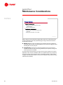
Chiller operation should be checked daily and recorded in an operating log.
Standard operating logs include: solution data; evaporator, absorber, and
46
TRG-TRC011-EN
period four
Maintenance Considerations
notes
condenser inlet and outlet temperatures; and purge operation. Logs are a
valuable tool for determining the onset of system problems.
This data may be obtained either manually or in conjunction with a building
automation system. The chiller controller should be capable of providing this
information quickly and easily. An automated control system is an efficient way
to identify operating changes and schedule maintenance before they become a
problem.
▲
◆
Pump teardown and inspection every 5 to 10 years
◆
Controls: no maintenance or calibration required
◆
Visually inspect overall unit
◆
Inspect safety controls and electrical components
Figure 56
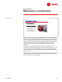
Absorption chillers typically include the following mechanical components:
pump(s) to circulate refrigerant and absorbent solution, a purge to remove
noncondensables from the chiller, a burner (if directly-fired), and a steam or hot
water control valve (if indirectly-fired).
Chiller manufacturers use different types of pumps. Some use a single pump,
while others use individual pumps. Some use hermetic pumps that are cooled
and lubricated by the pumped solution, and others use pumps with open
motors that require an external shaft seal. The pumps should be disassembled
and inspected at routine intervals. Be sure to consult the manufacturer for
specific recommendations.
With the advent of microprocessor-based controls, the control panel and
auxiliary controllers require no recalibration or maintenance. Remotelymounted electronic sensors send information to the chiller controller, which can
be connected to a building automation system to communicate information
and allow system-level optimization. These systems can notify the operator
with an alarm or diagnostic message when a problem occurs.
As for any mechanical equipment, a daily visual inspection of the chiller is
recommended to look for condensation, loosened electrical or control wiring,
or signs of corrosion. Special attention should be given to safety controls and
electrical components.
TRG-TRC011-EN
47
period four
Maintenance Considerations
notes
▲
◆
Check level of liquid refrigerant in purge
condensing unit
◆
Check vacuum pump oil
◆
Inspect purge condensing coil and clean as
necessary
◆
Change vacuum pump oil as needed
▲
Figure 57
Most purges are fully automatic and generally require less maintenance than
previous-generation manually operated purges. Purge-related maintenance
procedures are simple.
n Weekly: With the purge unit operating, check the purge tank condensing
activity by observing the liquid refrigerant level in the sump sight glass and
checking the vacuum pump oil.
n Semiannually: Inspect the air-cooled condensing-unit coil and clean as
needed. A fouled coil will reduce purge efficiency and capacity. Change the
vacuum pump oil as needed.
As mentioned in Period Three, the purge can be used to indicate an air leak or
depletion of the corrosion inhibitor. Leaks can be detected early by comparing
pump-out activity over the last 24 hours to the 30-day average. The hermetic
integrity of the absorption chiller is critical to its operation. Any leaks should be
addressed immediately.
48
TRG-TRC011-EN
period four
Maintenance Considerations
notes
▲
◆
Verify proper operation
◆
Inspect burner firing rate,
blower, linkage, and
safety controls
◆
Test run with alternate
fuel, if dual-fuel burner
▲
Figure 58
The burner is the heart of a direct-fired absorption chiller. Correct operation is,
therefore, necessary for optimum chiller performance. Daily checks should be
made in accordance with the manufacturer’s recommendations. Each cooling
season, the burner’s firing rate, blower, linkage, and safety controls should be
checked to ensure proper operation. If a dual-fuel burner is being used, it
should be periodically test run with the alternate fuel to ensure reliable
operation.
Manufacturers of direct-fired absorption chillers provide detailed burner
maintenance checklists, generally with maintenance requirements at 3-, 6-, and
12-month intervals. To ensure efficiency and increase longevity of both the
burner and the chiller, consult manufacturers’ maintenance manuals and follow
their instructions.
With indirect-fired absorption chillers, periodic inspection of the energy valve is
recommended to check for leaks. Again, consult manufacturers’ maintenance
manuals for specific recommendations.
TRG-TRC011-EN
49
period four
Maintenance Considerations
notes
▲
◆
Use a qualified water treatment
specialist
◆
Clean absorber and condenser
tubes as needed
◆
Clean waterside strainers
◆
Test tubes every 3 years
Figure 59
The use of better heat-transfer materials will reduce future maintenance costs.
The high-temperature generator, for example, contains high-temperature
lithium bromide solution that, when exposed to air and other noncondensables,
is more corrosive than in other sections of the chiller. Better materials in the
high-temperature generator will improve reliability and require less
maintenance. When selecting an absorption chiller, both installation and
maintenance costs must be considered when comparing different designs.
To ensure optimum heat transfer performance, the heat transfer surfaces must
be kept free of scale and sludge. Even a thin deposit of scale can substantially
reduce heat transfer capacity. Engage the services of a qualified water
treatment specialist to determine the level of water treatment required to
remove contaminants from the cooling water.
Scale deposits are best removed by chemical means. During this process, the
absorber and condenser are commonly isolated from the rest of the coolingtower-water circuit by valves, while a pump circulates cleaning solution through
the tubes.
Sludge is removed mechanically. This typically involves removing the water
boxes from the absorber and condenser, and loosening the deposits with a stiffbristled brush. The loosened material is then flushed from the tubes with clear
water. As part of this procedure, the strainers in both the chilled-water and
cooling-water circuits should be cleaned every year.
Every three years (more frequently in process or critical applications), a
qualified service organization should perform nondestructive inspections of the
tubes inside the generator(s), condenser, evaporator, absorber, and heat
exchanger(s). The eddy-current tube test is a common method.
50
TRG-TRC011-EN
period four
Maintenance Considerations
notes
▲
◆
Conduct annually or
semiannually
◆
Verifies corrosion inhibitor levels
◆
Verifies performance additive
levels
◆
Conduct annually
▲
Figure 60
An absorption chiller requires a very deep vacuum to operate efficiently. The
introduction of air and other noncondensables into the chiller will adversely
affect the chiller’s performance. In a lithium bromide absorption chiller, where
the absorbent is a salt, corrosion is a potential problem that must be avoided. It
may not be possible to completely prevent corrosion inside the chiller, although
it can be reduced or controlled by the addition of a chemical called a corrosion
inhibitor.
Corrosion inhibitors are primarily intended to protect the steel components of
the chiller from the corrosive action of the lithium bromide-and-water mixture.
The inhibitor is added to the lithium bromide solution to promote the formation
of a thin protective layer of oxide quickly and uniformly over the steel
components inside the chiller. This coating is more impervious to the reaction
with water, resulting in longer life for the chiller. Corrosion inhibitors also
reduce the production of noncondensable gas that is generated during the
corrosion process. The corrosion inhibitor, however, does not directly protect
the copper components from corrosion. Corrosion protection for the copper
heat transfer components primarily depends on the materials selected to
assure maximum design life.
Additionally, most lithium bromide absorption chillers use a chemical
performance additive to achieve and maintain design performance. This
additive considerably enhances the rate at which refrigerant vapor is absorbed
by the lithium bromide solution.
TRG-TRC011-EN
51
period four
Maintenance Considerations
notes
52
If air leaks into the chiller, the corrosion inhibitor is depleted as it reacts with the
air and produces hydrogen. To maintain chiller efficiency and ensure continued
corrosion protection, the lithium bromide solution must be analyzed
periodically to determine if corrosion inhibitor and performance additive levels
are within acceptable limits. This is the most important periodic maintenance
requirement! A laboratory test is required to determine these levels. Suggested
intervals for testing are once per year for comfort-cooling applications and
twice per year for chillers in continuous or critical service. Analysis of the
refrigerant is also recommended. Consult the chiller manufacturer for specific
corrosion inhibitor and performance additive recommendations.
TRG-TRC011-EN
period five
Application Considerations
notes
period five
Figure 61
Several considerations must be addressed when applying absorption water
chillers, including:
n Cooling-water temperature limitations
n Combination chiller plants
n Special considerations for direct-fired chillers
n Equipment rating standards
While not all-inclusive, this list does represent some of the key issues.
TRG-TRC011-EN
53
period five
Application Considerations
notes
cooling tower
bypass
diverting
valve
condenser
Figure 62
Cooling-Water Temperature Limitations
The temperature of the cooling water significantly impacts the operation of an
absorption chiller. As the temperature of the entering-cooling-water decreases,
chiller capacity increases.
Some absorption chiller designs can experience operational problems if the
cooling-water temperature changes too rapidly or becomes too low. If the
temperature of the cooling water changes too rapidly, there is potential for the
absorbent solution to carry over from the generator into the condenser. This
increases the risk of corrosion in the condenser and evaporator sections of the
chiller, and reduces the cooling capacity of the chiller. Additionally, low coolingwater temperatures increase the risk of crystallization. When applying these
chillers, a cooling tower bypass is typically recommended for stable control of
the cooling-water temperature.
In some new chiller and control designs, variable-speed drives are used to vary
the flow of solution through the chiller, allowing the chiller to maintain tight
control in situations where the cooling-water temperature may be highly
variable. In many cases, this means that a cooling tower bypass may not be
required, although this should be verified by the system designer. In
applications that require tight control of the leaving-chilled-water temperature,
however, it is still generally recommended to design the system to minimize the
rate at which the cooling-water temperature varies.
In all cases, the chiller manufacturer should be consulted for specific coolingwater temperature limitations and control requirements.
54
TRG-TRC011-EN
period five
Application Considerations
notes
cooling load
operate
absorption
chiller
operate
electric
chiller
1
2
3
4
5
operate
electric
chiller
6
7
8
9 10 11 12 1
2
3
onon-peak
on-peak
period
4
5
6
7
8
9 10 11 12
Figure 63
Combination Chiller Plants
Absorption chillers possess two operating characteristics that can noticeably
improve overall system efficiency and reduce system energy costs.
First, absorption chillers use fossil fuels rather than electricity. Operating
absorption chillers at times when on-peak electric energy and/or demand costs
are high reduces total system utility costs. In such installations, the absorption
chiller can operate during on-peak periods to avoid the high cost of electricity.
The electric chiller can run during off-peak periods to take advantage of the
lower cost of electricity.
Combination gas-and-electric plants can also exploit the heating capability of
direct-fired absorption chillers. Both electric and absorption chillers can be used
to provide summer cooling. If the electric chiller is large enough to satisfy the
entire winter cooling load, the direct-fired absorption chiller can be switched to
heating operation to either satisfy the entire winter heating load or supplement
the primary heating equipment. In such applications, selection of the directfired absorption chiller should be made to allow downsizing, or perhaps even
elimination of, the primary heating equipment.
TRG-TRC011-EN
55
period five
Application Considerations
notes
absorption
chiller
electric
chiller
58°F
[14.4°C]
50°F
42°F
[10°C]
[5.6°C]
Figure 64
The second beneficial operating characteristic is that an absorption chiller
works more efficiently and produces more cooling with increased leavingchilled-water temperatures.
Applications with two chillers can be either piped in series or in parallel.
Though there are advantages associated with each arrangement, the series
configuration allows a noticeable increase in the overall system efficiency of a
combination gas-and-electric chiller plant. The series arrangement allows the
upstream chiller to cool the water part of the way and uses the downstream
chiller to cool the water the rest of the way to the setpoint. Placing the
absorption chiller in the upstream position allows it to provide a warmer
leaving-chilled-water temperature, 50ºF [10ºC] in this example. This not only
improves the absorption chiller’s efficiency and capacity, but also reduces the
cooling load and energy consumption of the electric chiller.
The series arrangement also has the capability to preferentially load the gasburning chiller, allowing the system to maximize the use of lower-cost fuel
during periods of high electrical energy cost. Piping two chillers in series also
means that the entire system-water flow must pass through both chillers.
Exercise care when selecting the chillers to avoid exceeding their maximum
flow rates. Notice that the example series arrangement shown here also takes
advantage of a 16°F [8.9°C] temperature differential across the chillers. This
increased temperature differential allows the water flow rate to be reduced and
results in lower pumping costs.
Overall, the key to successful implementation of a combination gas-and-electric
chiller plant is an intelligent building automation system that optimizes chiller
plant operation relative to electrical and gas utility rate structures.
56
TRG-TRC011-EN
period five
Application Considerations
notes
cooling
tower
flue stack
exhaust duct
directdirect-fired
direct-fired
absorption chiller
Figure 65
Special Considerations for Direct-Fired Chillers
The combustion process that occurs in the burner is key to the operation of a
direct-fired absorption chiller. It also introduces several additional
considerations when applying this type of chiller.
n Combustion air requirements: Combustion equipment is designed and
operated to ensure complete combustion. Incomplete combustion uses fuel
inefficiently, can be hazardous because of carbon monoxide production, and
contributes to air pollution. The quantity of air to provide for a particular
direct-fired absorption chiller installation is determined by such factors as
expected variations in fuel and air supplies, system application, burner
design, and control requirements.
n Venting of exhaust: A flue exhaust-gas duct and stack must be installed to
effectively vent the products of combustion out of the building. This duct
and stack must be designed and installed in compliance with municipal,
state, and federal regulations. Also, be careful not to locate the stack too
close to the cooling tower.
n Gas train: The main gas control train regulates the fuel flow to the burner
manifold and provides safe operation. The gas train is selected based upon
the pressure of the gas main and local code requirements.
n NOx emissions: Nitrogen oxides (NOx) are the combustion emissions
containing nitrogen and oxygen in direct-fired absorption chiller
applications. Due to environmental concerns, some local building codes
require low NOx emissions. Manufacturers have developed low-NOx
burners that use various methods for reducing emissions. One cost-effective
method of achieving low emissions in commercial installations, flue-gas
recirculation, recycles flue gases to lessen NOx formation by reducing the
flame temperature and the amount of oxygen available for combustion.
TRG-TRC011-EN
57
period five
Application Considerations
notes
▲
◆
Combustion air ducted from
outside the machinery room
◆
Refrigerant vapor detector to
shut down combustion
process in the event of a
refrigerant leak
Figure 66
In general, ASHRAE Standard 15-1994, “Safety Code for Mechanical
Refrigeration,” does not apply to absorption water chillers due to Section 2.3,
which states:
This code does not apply where water is the primary refrigerant.
Section 8.13.6 of the Standard, however, does affect direct-fired absorption
chillers. It states:
No open flames that use combustion air from the machinery room
shall be installed where any refrigerant is used … Combustion
equipment shall not be installed in the same machinery room with
refrigerant-containing equipment except under one of the following
conditions:
(a) Combustion air is ducted from outside the machinery room and
sealed in such a manner as to prevent any refrigerant leakage from
entering the combustion chamber, or
(b) A refrigerant vapor detector is employed to automatically shut
down the combustion process in the event of refrigerant leakage.
When halocarbon refrigerants (such as HCFC-123, HCFC-22, HFC-134a, etc.) are
present during a combustion process, they can break down into products that
are both harmful to humans and corrosive to machinery. The intent of
Standard 15 is to avoid both of these hazards by preventing refrigerant
exposure to any combustion process. Thus, the use of an open-flame device,
such as a boiler or the burner of a direct-fired absorption chiller, in a machinery
room is strictly prohibited by this section unless one of the exceptions is
employed.
Exception (a) allows combustion air to be ducted to the open-flame device from
outside the machinery room in order to prevent air (and refrigerants) present in
the machinery room from entering the flame. Alternatively, exception (b) allows
58
TRG-TRC011-EN
period five
Application Considerations
notes
a refrigerant vapor detector to monitor refrigerant levels in the machinery
room. When the detector measures refrigerant levels above those allowable, a
building automation system is used to automatically shut down the combustion
process. Due to the lower cost, many building owners employ exception (b) in
machinery rooms that have direct-fired absorption chillers or boilers.
▲
◆
Establish definitions, testing,
and rating requirements
◆
Single- and double-effect
absorption chillers
◆
Indirect- and direct-fired
absorption chillers
◆
Water-and-lithium bromide
solution
▲
Figure 67
Equipment Rating Standards
The Air Conditioning & Refrigeration Institute (ARI) establishes rating standards
for packaged HVAC equipment. The overall objective of ARI Standard 560 is to
promote consistent rating of many types and sizes of absorption water chillers.
It covers single-effect chillers operating on steam or a hot fluid, double-effect
chillers operating on steam or a hot fluid, and direct-fired double-effect chillers
operating on natural gas, oil, or liquid petroleum (LP). It pertains to chillers
using water as the refrigerant and lithium bromide as the absorbent.
The standard rating conditions used for ARI rating represent typical design
temperatures and flow rates for which water-cooled systems are designed.
They are not suggestions for good design practice for a given system—they
simply define a common rating point to aid comparisons. Trends toward
improved system energy efficiency have changed some of the actual conditions
for specific applications.
Impurities in the chilled- and cooling-water systems eventually deposit on
evaporator, absorber, and condenser tube surfaces, impeding heat transfer.
Catalogued performance data includes a fouling factor that accounts for this
effect to more closely predict actual chiller performance.
Remember that the ARI rating is a standardized representation. Many chillers
do not run at standard rating conditions. Performing a comprehensive energy
analysis is still the best method of comparing the system operating cost
difference between two chillers.
TRG-TRC011-EN
59
period six
Review
notes
period six
Figure 68
We will now review the main concepts that were covered in this clinic on
absorption water chillers.
steam or
hot water
generator
condenser
evaporator
chilled
water
heat
exchanger
expansion
device
absorber
cooling
water
Figure 69
Period One presented the basic single-effect, absorption refrigeration cycle. In
the generator, dilute solution absorbs heat from the steam or hot water
flowing through the tubes, causing the refrigerant to boil and separate from the
absorbent solution. As the refrigerant boils away, the absorbent solution
becomes concentrated and returns to the absorber. The resulting refrigerant
vapor migrates to the cooler condenser, where heat transfers from the hot
refrigerant vapor to the cooling water inside the tubes, causing the refrigerant
to condense on the tube surfaces. The resulting condensed liquid refrigerant
flows through an expansion device, causing a pressure drop that reduces the
refrigerant pressure to that of the evaporator. This pressure reduction causes a
small portion of the liquid refrigerant to boil off, cooling the remaining
refrigerant to the desired evaporator temperature. The cooled mixture of liquid
60
TRG-TRC011-EN
period six
Review
notes
and vapor refrigerant then flows into the evaporator pan, from which the
evaporator spray pump continuously pumps the liquid refrigerant to be
sprayed over the tubes. As heat transfers from the chilled water flowing
through the tubes to the cooler refrigerant, the refrigerant boils (vaporizes) and
the resulting refrigerant vapor is drawn into the absorber.
Inside the absorber, the refrigerant vapor is absorbed by the lithium bromide
solution, releasing heat to the cooling water which is circulated through the
tubes. Absorption of the refrigerant vapor creates a low pressure area within
the absorber, inducing a continuous flow of refrigerant from the evaporator to
the absorber. The absorber spray pump mixes concentrated absorbent
solution (returning from the generator) with dilute solution (from inside the
absorber) and delivers this intermediate solution to the absorber sprays. The
lithium bromide solution becomes diluted as it absorbs the refrigerant. To
complete the cycle, the generator pump continuously returns the dilute
absorbent solution to the generator to be reconcentrated. This cool dilute
solution passes through a heat exchanger to be preheated by the hot
concentrated solution returning from the generator.
Figure 70
Period Two discussed the various types of absorption water chillers, including
the single-effect, double-effect, and direct-fired chillers.
The double-effect absorption chiller includes the same basic components as the
single-effect chiller, and also includes an additional generator, heat exchanger,
and pump. The high-temperature generator can use steam or a hot liquid such
as water as the energy source (indirect-fired) or the combustion of a fossil fuel
such as natural gas or oil as the energy source (direct-fired).
This period also introduced the use of the direct-fired absorption chiller/heater
to provide both cooling and heating.
TRG-TRC011-EN
61
period six
Review
notes
▲
◆
Vary solution flow to generator
◆
Vary heat input to generator
◆
High-quality construction
◆
Microelectronic controls
◆
Automatic purge systems
◆
De-crystallization devices
▲
▲
Figure 71
Period Three explained the part-load operation of the absorption chiller. It
described the use of energy valves, burner controls, throttling and bypass
valves, and adjustable-frequency drives as methods for controlling the capacity
on the chiller. Valves and AFDs are used to vary the flow rate of solution to the
generator. Modulating energy valves and burner controls are used to vary the
heat input to the generator.
It also introduced the concept of crystallization, which occurs when the
absorbent solution becomes saturated and the salt begins to leave the solution
as a solid. Causes of crystallization include: air and other noncondensable
gases leaking into the chiller, cooling water that is too cold or that fluctuates in
temperature too rapidly, and an electric power failure. In most modern
absorption chiller designs, high-quality construction, smart microelectronic
controls, and automatic purge systems are extremely effective in avoiding
crystallization. Additionally, most absorption water chillers include devices that
allow the chiller to recover in the event that crystallization does occur.
The operation of the purge system as a means of removing air and other
noncondensables from inside the chiller was also presented.
62
TRG-TRC011-EN
period six
Review
notes
▲
◆
Operating log
◆
Mechanical components
◆
Heat transfer surfaces
◆
Absorbent solution analysis (corrosion inhibitor and
performance additive levels)
Figure 72
Period Four described general maintenance requirements for absorption water
chillers, including:
n Recommended data for a daily log
n Recommended maintenance for mechanical components, such as the
solution and refrigerant pumps, purge, and burner
n Recommended maintenance for heat-transfer surfaces
n Required analysis of the absorbent solution to ensure acceptable levels of
the corrosion inhibitors and performance additives
▲
◆
Cooling-water temperature limitations
◆
Combination gas-and-electric chiller plants
◆
Special considerations for direct-fired chillers
◆
Equipment rating standards
Figure 73
Period Five presented several considerations for applying absorption water
chillers. These included cooling-water temperature limitations, the advantages
of using combination gas-and-electric chiller plants, special considerations
when using direct-fired chillers, and equipment rating standards.
TRG-TRC011-EN
63
period six
Review
notes
Figure 74
For more information, refer to the following references:
n Trane product catalogs for absorption water chiller products (Trane literature
order numbers ABS-DS-1, ABS-DS-4, ABS-DS-6, and ABS-PRC001-EN)
n Absorption Chiller System Design Applications Engineering Manual (Trane
literature order number SYS-AM-13)
n Trane Air Conditioning Manual
n Equilibrium Chart for Aqueous Lithium Bromide Solutions laminated chart,
I-P units (Trane literature order number 1-43.198)
n ASHRAE Handbook – Fundamentals
n ASHRAE Handbook – Refrigeration
Visit the ASHRAE Bookstore at www.ashrae.org.
For more information on additional educational materials available from Trane,
contact your local Trane office (request a copy of the Educational Materials
catalog—Trane order number EM-ADV1) or visit our online bookstore at
www.trane.com/bookstore/.
64
TRG-TRC011-EN
Quiz
Questions for Period 1
1 What are the names of the two working fluids used within the absorption
cycle?
%
$
'
)
&
(
Figure 75
2 Identify the components of the absorption refrigeration cycle labeled in
Figure 75.
3 What are the two major components on the high-pressure side of the
absorption refrigeration cycle? What are the two major components on the
low-pressure side of the cycle?
4 Does the absorption cycle operate at pressures above or below
atmospheric pressure?
5 Which of the following components do not contain absorbent solution?
(generator, condenser, evaporator, absorber, heat exchanger)
6 What is the purpose of the heat exchanger in the absorption refrigeration
cycle?
Questions for Period 2
7 What additional components are included on a double-effect absorption
chiller versus a single-effect chiller?
8 Which type of absorption water chiller is capable of providing simultaneous
cooling and heating?
TRG-TRC011-EN
65
Quiz
Questions for Period 3
9 Does an increase in solution concentration, assuming a constant solution
temperature, result in an increase or decrease in vapor pressure?
10 What is crystallization?
11 What are the most common causes of crystallization in an absorption chiller
and how can these conditions be avoided?
Questions for Period 4
12 What is the purpose of analyzing the lithium bromide solution?
Questions for Period 5
13 True or False: All absorption water chillers require the use of a cooling
tower bypass for stable control of the cooling-water temperature.
14 List two special considerations discussed in this clinic for applying directfired absorption water chillers.
66
TRG-TRC011-EN
TRG-TRC011-EN
67
Answers
1 Refrigerant (distilled water) and absorbent (lithium bromide)
2 $ generator, % condenser, & expansion device, ' evaporator, ( absorber,
) heat exchanger
3 Generator and condenser; evaporator and absorber
4 Below atmospheric pressure
5 Condenser and evaporator
6 To preheat the dilute solution returning to the generator, which reduces the
heat energy required to boil the refrigerant, and precool the concentrated
solution returning to the absorber, which reduces the flow rate of cooling
water required to absorb heat in the absorber.
7 High-temperature generator, high-temperature heat exchanger, and
possibly an additional pump (depending on the type of flow cycle used)
8 Direct-fired absorption chiller (with an auxiliary heating bundle)
9 Decrease in vapor pressure
10 The process of lithium bromide leaving the solution as a solid when the
absorbent solution is cooled below its saturation temperature.
11 Air leaking into the chiller, avoided by quality construction and automatic
purging. Cooling water that is too cold or that fluctuates in temperature too
rapidly, avoided by using improved microelectronic controls or a cooling
tower bypass. Electric power failure, avoided by gravity-fed dilution cycles.
12 To determine if corrosion inhibitor and performance additive levels are
within acceptable limits. Air leaking into the chiller can deplete the
corrosion inhibitor.
13 False. Many new chiller and control designs are able to maintain control of
the cycle, even in situations where the cooling-water temperature may be
highly variable.
14 Quantity of combustion air required, venting of combustion exhaust, sizing
of the main gas train, requirements for low NOx emissions, and compliance
with ASHRAE Standard 15.
68
TRG-TRC011-EN
Glossary
absorbent A substance used to absorb refrigerant and transport it from the
low-pressure to the high-pressure side of the absorption refrigeration cycle. In
absorption water chillers, the absorbent is commonly lithium bromide.
absorber A component of the absorption refrigeration system where
refrigerant vapor is absorbed by the absorbent solution and rejects heat to
cooling water.
adjustable-frequency drive (AFD) A device used to control the capacity of a
pump by varying the speed of the pump motor.
ARI Air Conditioning & Refrigeration Institute.
ARI Standard 560 A publication, titled “Absorption Water Chilling and Water
Heating Packages,” used to promote consistent rating methods for many types
and sizes of absorption water chillers, using water as the refrigerant and lithium
bromide as the absorbent. It covers single-effect chillers operating on steam or
a hot fluid; indirect-fired double-effect chillers operating on steam or a hot fluid;
and direct-fired double-effect chillers operating on natural gas, oil, or liquid
petroleum (LP).
ASHRAE American Society of Heating, Refrigerating and Air-Conditioning
Engineers.
ASHRAE Standard 15 A publication, titled “Safety Code for Mechanical
Refrigeration,” that specifies safe design, construction, installation, and
operation of refrigerating systems.
auxiliary heating bundle A separate heat exchanger added to a direct-fired
absorption chiller to allow it to provide simultaneous cooling and heating.
chilled water The cold water produced by the chiller (flowing through the
tubes in the evaporator) and pumped to the air-handler coils throughout the
building.
chilled-water system Uses water as the cooling media. The refrigerant inside
the evaporator absorbs heat from the water and this water is pumped to coils in
order to absorb heat from the air used for space conditioning.
coefficient of performance (COP) A dimensionless ratio used to express the
efficiency of a refrigeration machine. For an absorption water chiller, it is
defined as the ratio of evaporator cooling capacity divided by the heat energy
required by the generator, excluding the electrical energy needed to operate the
pumps, purge, and controls. A higher COP designates a higher efficiency.
compressor A mechanical device used in the vapor-compression refrigeration
cycle to increase the pressure and temperature of the refrigerant vapor.
concentrated absorbent solution A mixture of refrigerant and absorbent that
has a relatively low refrigerant content and high absorbent content.
TRG-TRC011-EN
69
Glossary
condenser A component of the absorption refrigeration system in which
refrigerant vapor is converted to liquid as it rejects heat to cooling water.
cooling water Water obtained from a source (cooling tower, river, pond) to
which heat is rejected. This water flows through tubes in the absorber and the
condenser.
corrosion inhibitor Chemical added to the absorbent solution to protect the
steel components of the chiller from the corrosive action of the water and
lithium bromide solution.
crystallization The process of the absorbent leaving the solution as a solid,
when the solution is cooled below its saturation temperature.
dilute absorbent solution A mixture of refrigerant and absorbent that has a
relatively high refrigerant content and low absorbent content.
direct-fired A type of absorption chiller that uses the combustion of a fossil
fuel (such as natural gas or oil) directly to provide heat to the high-temperature
generator.
double-effect A type of absorption chiller that uses two generators, a hightemperature generator and a low-temperature generator.
equilibrium chart A graphical representation of the properties of lithium
bromide solutions. Vapor pressure is plotted on the vertical axis, solution
temperature on the horizontal axis, and concentration on the diagonal lines.
evaporator A component of the absorption refrigeration system where cool
liquid refrigerant absorbs heat from water (from the building system), causing
the refrigerant to boil.
expansion device A component of the absorption refrigeration system used to
reduce the pressure and temperature of the refrigerant to desired evaporator
conditions.
flash The process of liquid refrigerant being vaporized by a sudden reduction
of pressure.
generator A component of the absorption refrigeration system in which
refrigerant vapor boils and is separated from the absorbent solution as it
absorbs heat from the primary heat source.
indirect-fired A type of absorption chiller that uses steam or a hot fluid (such
as water) from an external source to provide heat to the generator.
intermediate absorbent solution A mixture of refrigerant and absorbent that
is a combination of dilute and concentrated solutions.
performance additive Chemical added to the absorbent solution to enhance
the rate at which refrigerant vapor is absorbed by the lithium bromide solution,
improving the performance of the cycle.
70
TRG-TRC011-EN
Glossary
purge A device used to remove air and other noncondensable gases that may
leak into the low-pressure absorption chiller.
refrigerant A substance used to absorb and transport heat for the purpose of
cooling. In a large absorption water chiller, the refrigerant is distilled water.
saturation temperature The temperature, for a given concentration, at which
the solution contains the most salt that it can hold. If the temperature drops any
further, the salt begins to leave the solution in a solid form (crystallize).
single-effect A type of absorption chiller that uses a single generator.
throttling pipe A type of expansion device used in absorption water chillers. It
is a section of pipe with an orifice inside.
variable-speed drive
TRG-TRC011-EN
See adjustable-frequency drive.
71
Literature Order Number
The Trane Company
Worldwide Applied Systems Group
3600 Pammel Creek Road
La Crosse, WI 54601-7599
www.trane.com
An American Standard Company
TRG-TRC011-EN
File Number
E/AV-FND-TRG-TRC011-0400-EN
Supersedes
2803-11-677
Stocking Location
La Crosse
Since The Trane Company has a policy of continuous product improvement, it reserves the right to change
design and specifications without notice.