1
Section 61221002L2-5B
Issue 2, August 2003
CLEI Code: SLL5R3DG_ _
ADTRAN® AHDSL2
Asynchronous H2TU-C Line Card for
Alcatel Litespan® Channel Bank Assemblies Using Narrowband Pairs
Installation and Maintenance Practice
CONTENTS
1. General ......................................................................... 1
2. Applications ................................................................. 3
3. Installation .................................................................... 3
4. Deployment Guidelines ............................................... 8
5. Maintenance ................................................................. 9
6. Troubleshooting Procedures ...................................... 10
7. Product Specifications ............................................... 10
8. Warranty and Customer Service ................................ 10
Appendix A. HDSL2 Loopbacks .................................. A-1
Appendix B. TL1 H2TU-C Tutorial .............................. B-1
Appendix C. Metallic Test Access Unit (MTAU)
Testing Capabilities .................................. C-1
FIGURES
Figure 1. ADTRAN H2TU-C for Litespan .................... 1
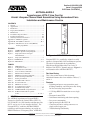
Figure 2. H2TU-C Span Powering Diagram .................. 3
Figure 3. Deployment from a Litespan
Channel Bank .................................................. 3
Figure 4. Deployment Guidelines .................................. 8
Figure C-1. SPLIT Mode ................................................ C-1
Figure C-2. MON Mode ................................................. C-2
TABLES
Table 1.
Table 2.
Table 3.
Table 4.
Table 5.
Table 6.
Table 7.
Table 8.
Table 9.
Table 10.
Table 11.
Table 12.
Table 13.
Table 14.
Table A-1.
LED Indicators ................................................ 2
Compliance Codes .......................................... 4
Administration Commands ............................. 5
Cross-Connect Commands.............................. 5
Maintenance Commands ................................. 5
HDSL Provisioning Commands ..................... 6
T1 Provisioning Commands ........................... 6
Testing Commands ......................................... 7
Worksheet PW-1 Factors ................................ 8
Power Parameters ............................................ 8
HDSL2 Loss Values ........................................ 9
Loop Insertion Loss Data ................................ 9
Troubleshooting Guide ................................. 10
ADTRAN H2TU-C Specifications ............... 11
In-Band Addressable Loopback
Codes .................................................. A-2, A-3
1. GENERAL
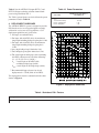
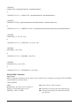
The ADTRAN asynchronous Litespan HDSL2
Transceiver Unit for the Central Office (H2TU-C)
P/N 1221002L2, is a DS1 interface unit that provides
full T1 service over 2-wire interface facilities. The
Litespan H2TU-C combines ADTRAN HDSL2
technology and Litespan technology to provide an
HDSL2 interface to a Litespan system. ADTRAN’s
61221002L2-5B
H TUC
1221002L2 NB
DSL
STAT
RLOS
HLOS
HCRC
ARM
LBK
B8ZS
AHDSL2
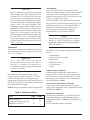
Figure 1. ADTRAN H2TU-C for Litespan
Litespan H2TU-C is certified by Alcatel® to safely
operate in Litespan 2000, 2012 and Starspan systems.
The unit is licensed under the Asynchronous
High-bit-rate Digital Subscriber Line 2-wire T1
Interface Unit H2TU-C channel unit type. Figure 1 is
an illustration of the ADTRAN H2TU-C.
Revision History
This is the second release of this document.
Additional footnotes have been added to Tables 6, 7,
and A-1.
Features
• Lightning and power cross-protection, static
discharge immunity, and local power bus fusing
for line card safety and protection
• 1.552 kbps HDSL2 transmission over a single
pair
• Front panel status LEDs
• Performance monitoring and alarm reporting
• Low power consumption
• Span powering for the H2TU-R
• Corrosion-preventive sealing current over a
single twisted copper pair
• Troubleshooting functionality
Trademarks: Any brand names and product names included in this document are
trademarks, registered trademarks, or trade names of their respective holders.
1
Table 1 lists and defines the H2TU-C Front Panel
LED indicators.
Each ADTRAN Litespan H2TU-C line card provides
a 1.552 kbps data transport over one unconditioned
CSA copper pair. These CSA loops can range up to 12
kft of 24-AWG twisted pair wire.
The Litespan H2TU-C can be used in Litespan 2000,
Litespan 2012, and Litespan ONU channel bank
assembly (CBA) systems containing Litespan system
software versions of 11.0.0 or higher. Each H2TU-C
works with the following multiple list versions of the
HDSL2 unit remote end (H2TU-R):
Part Number
Description
1222024L6
T200 H2TU-R, Local Power
1223024L9
T200 H2TU-R, Local Power
1221026L6
T200 H2TU-R MON
1222026L6
T200 H2TU-R MON
1222026L9
T200 H2TU-R Q
1223026L9
T200 H2TU-R Q
122x024L7
T200 H2TU-R, Local Power
122x026L1
T200 H2TU-R
122x026L5
T200 H2TU-R B
122x026L7
T200 H2TU-R S
(where x = 1, 2 or 3)
The H2TU-C can be deployed in circuits consisting of
one H2TU-C and one H2TU-R. Lightning and power
cross-protection is provided at each twisted pair
interface of the ADTRAN H2TU-C line card. Local
power bus fusing is also used to protect the Litespan
channel bank backplane, Litespan bank power
supplies, and neighboring Litespan line cards in the
event of catastrophic line card failure.
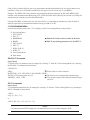
The Litespan H2TU-C uses a DC-to-DC converter to
derive span powering voltage from the Litespan
–48 VDC switched battery supply.
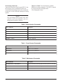
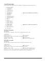
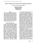
Simplex current of 30 mA of current may be coupled
onto the HDSL2 loop span to power the H2TU-R (see
Figure 2).
NOTE
Depending on the type of H2TU-R used in the
circuit, different provisioning options will be
available.
Table 1. LED Indicators
LED
STAT
HLOS
RLOS
DSL
Indication
Description
Off
Green
Flashing Green
Red
Indicates loss of power to H2TU-C
Normal operation; H2TU-C is in sync with the H2TU-R
Acquiring HDSL2 synchronization with H2TU-R
Failure indication; unable to start/load firmware
Off HDSL2 signal achieved
Red HDSL2 loss of synchronization
Flashing Red DC continuity fault detected on HDSL2 loop
Off DS1 signal from the CPE is present at H2TU-R
Red DS1 signal from the CPE is absent at H2TU-R or Framing does not match
Green
Yellow
Red
Flashing
HDSL2 SNR margin is optimum (6 dB or greater)
HDSL2 SNR margin is marginal (1 dB to 5 dB)
HDSL2 SNR margin is poor (0 dB)
HDSL2 pulse attenuation is > 30 dB
HCRC
Off No HDSL2 CRC errors within the last 30 minutes
Yellow Four or more HDSL2 CRC errors in last 30 minutes
Red HDSL2 CRC errors are being detected
ARM/LBK
Off The unit is not armed or in loopback
Green The unit is in loopback
Yellow The unit is armed but not in loopback
B8ZS
2
Green The line code is B8ZS
Off The line code is AMI
61221002L2-5B
3. INSTALLATION
SPAN CURRENT
C A U T I O N !
TIP (+)
HDSL2
SPAN POWER
−190V
RING (−)
Figure 2. H2TU-C Span Powering Diagram
2. APPLICATIONS
The ADTRAN HDSL2 system provides a
cost-effective alternative for deploying T1 service
over metallic cable pairs. In contrast with traditional
T1 service equipment, ADTRAN HDSL2 can be
successfully deployed over one unconditioned,
nonloaded, bridged-tapped copper pair CSA loop (see
Deployment Guidelines, Section 4).
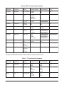
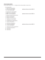
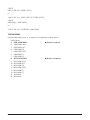
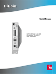
Litespan HDSL2 deployment is typically made from a
Litespan 2000, Litespan 2012, or Litespan ONU
channel bank assembly. Figure 3 shows possible
ADTRAN HDSL2 deployments from a Litespan
channel bank assembly. ADTRAN HDSL2 systems
can be deployed quickly without the use of expensive
T1 repeater equipment on standard CSA loops while
using the existing massive copper-fed twisted line
pairs in use by the industry.
ADTRAN uses negative ground-referenced span
powering voltage (–190 VDC) on HDSL2 loop.
H2TU-R span powering can be disabled to allow
locally powered H2TU-R applications, if desired.
Litespan 2000 or 2012 System with Litespan H2TU-C deployment
Common
Control
Channel Bank
Assembly with
a Litespan
H2TU-C
Installed
HDSL2 Loop Pair
HDSL2 Unit
Remote End
Typical Starspan System
HDT
Common
Control
OLNK
High-Density
Fiber Bank
ONU-96 with
an installed
Litespan H2TU-C
SUBJECT TO ELECTROSTATIC DAMAGE
OR DECREASE IN RELIABILITY.
HANDLING PRECAUTIONS REQUIRED.
After unpacking the unit, inspect it for damage. If
damage is noted, file a claim with the carrier, then
contact ADTRAN. Refer to Warranty and Customer
Service.
The Litespan H2TU-C plugs directly into a Litespan
channel bank assembly channel unit slot. Litespan
system software must be version 11.0.0 or higher.
The tip and ring connections from the H2TU-C to the
shelf are made through the following card edge pins:
• Narrowband Tip – Pin A3
• Narrowband Ring – Pin A4
CAUTION
Do not deploy the Litespan H2TU-C into any
Litespan channel bank assembly slot that has
ADSL Power Distribution Fuse and Alarm
(PDFA) connections to the wideband pairs of
the channel bank assembly.
This unit supports narrowband cabling only on the
Litespan RT shelf. For more information regarding
cabling, reference Alcatel document Mechanical Unit
Descriptions, OSP 363-405-270.
Upon insertion of an H2TU-C into an unprovisioned
slot, the STAT LED should turn red immediately.
The STAT LED will remain red until the Litespan
bank recognizes the insertion of the card and
downloads the AHDSL2 channel unit type code into
the line card. Typically, the STAT LED will remain
red for approximately 15 to 20 seconds (time may
vary). Approximately 3 to 4 seconds after the STAT
LED turns off, the HLOS LED will turn red and
remain so until the H2TU-C and H2TU-R units
synchronize with each other over the HDSL2 loop.
The STAT LED will turn green after synchronization
of the HDSL2 loop.
HDSL2 Loop Pair
HDSL2 Unit
Remote End
Figure 3. Deployment from a Litespan
Channel Bank
61221002L2-5B
3
CAUTION
Prior to installing or removing the Litespan
H2TU-C, observe the following warning: If the
Litespan H2TU-C is removed from a line card
slot, wait at least 15 seconds before reinsertion.
If connected to the MTI craft interface terminal,
wait until the message “AID:MJ,UEQ.” appears
(where “AID” is the access identifier). This
informs the Litespan common control assembly
that the H2TU-C has been removed from its slot,
after which the common control assembly begins
looking for the reinsertion of the line card.
Reinsertion any earlier than this may temporarily
lock the H2TU-C into a nonfunctional state
because the common control assembly will not
send the AHDSL2 equipment type code to the
H2TU-C line card.
Compliance
This product is intended for installation in restricted
access locations only and in equipment with a Type
“B” or “E” enclosure.
WARNING
Up to –200 VDC may be present on
telecommunications wiring. The DSX-1
interface is intended for connection to
intra-building wiring only. Ensure chassis ground
is properly connected.
This product provides span powering voltage
(negative only with respect to ground, –190 VDC
nominal, GFI protection < 5 mA) and meets all
requirements of Bellcore GR-1089-CORE (Class A2)
and ANSI T1.418-2002. This product is NRTL listed
to the applicable UL standards.
Table 2 shows the compliance codes for this product.
Table 2. Compliance Codes
Code
Power Code (PC)
Telecommunication Code (TC)
Installation Code (IC)
4
Input
Output
F
–
A
C
X
–
Provisioning
Provisioning of the H2TU-C is through the craft
interface on the Maintenance and Test Interface (MTI)
card either via TL1 commands or the Litecraft Pro
Graphical User Interface (GUI). Refer to the Litecraft
Pro Access Configuration Guide
(P/N 61221002L1-31) for detailed GUI information.
The provisioning and performance monitoring VT100
terminal screens may be viewed from the H2TU-R
DB-9 RS-232 craft interface port. However, the
provisioning options may not be changed or
manipulated in any way from the H2TU-R.
NOTE
Please reference Alcatel document TL1 Software
Reference, OSP 363-405-502 for detailed
information regarding provisioning through the
MTI craft interface.
The H2TU-C TL1/Litecraft commands are grouped as
follows:
•
•
•
•
•
•
Administration
Cross-Connect Provisioning
Maintenance
HDSL Provisioning
T1 Provisioning
Testing
Administration Commands
Administration commands are used to remove or
restore the H2TU-C to service, place equipment and
facilities In-Service (IS) and Out-of-Service (OOS),
and display system inventory. These commands are
listed and defined in Table 3.
Cross-Connect Provisioning Commands
Cross-connect Provisioning commands are used to
manage cross-connections. These commands are listed
and defined in Table 4.
Maintenance Commands
Maintenance commands are use to clear and retrieve
Performance Monitoring (PM) information and to
display alarm Statistics. Table 5 lists and defines the
available
TL1/Litecraft Maintenance commands.
61221002L2-5B
Provisioning Commands
Upon initial insertion of the Litespan H2TU-C into
the Litespan system, configuration options are
downloaded automatically to the line card and take
precedence over the ADTRAN default provisioning
options.
Table 6 and Table 7 list and define the available
HDSL provisioning commands. The H2TU-C should
be pre-provisioned as indicated under
“Pre-Configurable Value.”
NOTE
The provisioning options stored in the shelf
controller can be pre-configured by the user
through the Litecraft Pro interface.
Table 3. Administration Commands
TL1 Commands
Description
RMV-HDSL
Removes the Litespan H2TU-C from service (OOS)
RST-HDSL
Restores the Litespan H2TU-C to service (IS)
ENT-EQPT
Enters or assigns a unit to a slot position
DLT-EQPT
Deletes or unassigns a unit to a slot position
ED-HDSL or ED-T1
Edits the equipment
Table 4. Cross-Connect Commands
TL1 Commands
Description
ENT-CRS-T1
Enters a cross-connection
DLT-CRS-T1
Deletes a cross-connection
RTRV-CRS-T1
Retrieves existing cross-connections
Table 5. Maintenance Commands
TL1 Commands
Description
INIT-REG-HDSL or INIT-REG-T1
Clears performance monitoring data and sets all values to zero (0)
RTRV-PM-HDSL or RTRV-PM-T1
Retrieves performance monitoring data
RTRV-ALM-HDSL
Retrieves alarms
61221002L2-5B
5
Table 6. HDSL Provisioning Commands
TL1
Commands
Litecraft
Parameters
H2TU-C
Options
H2TU-C
Available Settings
Corresponding
Litecraft Settings
Pre-Configurable
Value
ED-HDSL
NIDLPBK
NIU Loopback
Disabled
Enabled
NO
YES
YES
ED-HDSL
LPBKTMO
Loopback Time 0
20 Minutes
Out1
60 Minutes
120 Minutes
0
20
60
120
120
ED-HDSL
LPBKACTR
New England
Loopback2
Disabled
Enabled
0000000000000000
0000000000000001
0000000000000000
ED-HDSL
FT1MODE
Latching
Loopback
T1
FT1
NO
YES
NO
ED-HDSL
LP
Span Power
Disabled
Enabled
SINK
SOURCE
SOURCE
ED-HDSL
LPBKDEACTCDE Customer Loss
Indicator3
AIS
AIS/CI
Loopback
0000000000000000
0000000000000001
0000000000000010
0000000000000001
ED-HDSL
LPBKACTC
PRM setting1,3
None
SPRM
NPRM
Auto (Both)
0000000000000000
0000000000000001
0000000000000010
0000000000000011
0000000000000001
ED-HDSL
NTWKKPALV
Network Keep
Alive
Disabled
Enabled
NO
YES
NO
ED-GOS-HDSL SNR
SNR Margin
Alarm
Threshold
0 to 15 dB
0 to 15
ED-GOS-HDSL LA
Loop
Attenuation
Alarm
Threshold
0 to 40 dB
0 to 40
1
Some settings may not be available at the H2TU-R.
This option is available only if the H2TU-R P/N 1221026L1, 1222026L1 or 1223026L1 is used in the circuit.
3
This option is not available if the H2TU-R P/N 1221026L6, 1222026L6 or 1223026L1 is used in the circuit.
2
Table 7. T1 Provisioning Commands
1
TL1
Commands
Litecraft
Parameters
H2TU-C
Options
H2TU-C
Available Settings
Corresponding
Litecraft Settings
Pre-Configurable
Value
ED-T1
LINECDE
Line Code
AMI
B8ZS
AMI
B8ZS
B8ZS
ED-T1
FMT
Framing1
SF
ESF
Unframed
AUTO
SF
ESF
UNFR
AUTO
AUTO
ED-T1
AT
DS1 TX Level1 0 dB
−7.5 dB
−15 dB
0.0
7.5
15.0
0.0
Some settings may not be available at the H2TU-R.
6
61221002L2-5B
Testing Commands
The H2TU-C testing commands are used to initiate and
terminate loopbacks and disconnect for testing
purposes. Table 8 lists and defines the TL1/Litecraft
testing commands.
NOTE
Before entering loopbacks, the user needs to
remove the card from service. This can be done
with the RMV-HDSL command. The card can
then be restored to service with the RST-HDSL
command.
NOTE
When entering access identification (AID), the
user needs to specify whether a loopback
command is for a C or an R. For example,
AID=RT-1-21-C.
Alarms
The selectable alarm threshold crossing alerts are as
follows:
• SNR margin threshold
• HDSL2 and DS1 15-minute ES, SES, UAS
thresholds
• HDSL2 and DS1 daily ES, SES, UAS thresholds
• HDSL2 loop attenuation threshold
• DS1 15-minute CV-L, B8ZSS-L, and PDVS-L
thresholds
• DS1 daily CV-L, B8ZSS-L, and PDVS-L
thresholds
The following additional alarm conditions are
provided by the H2TU-C:
• HDSL2 LOSW alarm
• HDSL2 unit failure alarm
• HDSL2 loop continuity alarms
• HDSL2 circuit reset
• DS1 LOS alarm
• H2TU-R AIS, RAI, INCRAI-CI
Power Requirements
When deploying any Litespan H2TU-C, the power
requirements for the application should also be
considered for product mix calculations and
maximum number of Litespan H2TU-Cs within a
channel bank assembly. Use Worksheet PW-1 in the
“Engineering and Planning” section of Alcatel
practice, OSP TL1 Software Documentation, release
7.1 or higher, to determine whether a particular
combination of channel units is within power-drain
specifications.
Table 8. Testing Commands
TL1
Commands
Litecraft
Parameters
H2TU-C
Options
H2TU-C Available
Settings
Corresponding
Litecraft Settings
OPR-LPBK-HDSL
LOCN (AID-C)
H2TU-C Network Loopback
Loop Up
NEND
RLS-LPBK-HDSL
LOCN (AID-C)
H2TU-C Network Loopback
Loop Down
NEND
OPR-LPBK-HDSL
LOCN (AID-C)
H2TU-C Customer Loopback
Loop Up
FEND
RLS-LPBK-HDSL
LOCN (AID-C)
H2TU-C Customer Loopback
Loop Down
FEND
OPR-LPBK-HDSL
LOCN (AID-R)
H2TU-R Network Loopback
Loop Up
NEND
RLS-LPBK-HDSL
LOCN (AID-R)
H2TU-R Network Loopback
Loop Down
NEND
OPR-LPBK-HDSL
LOCN (AID-R)
H2TU-R Customer Loopback
Loop Up
FEND
RLS-LPBK-HDSL
LOCN (AID-R)
H2TU-R Customer Loopback
Loop Down
FEND
61221002L2-5B
7
Table 10. Power Parameters
Table 9 lists the ADTRAN Litespan H2TU-C and
H2TU-R factors needed to calculate channel bank
power using Worksheet PW-1.
ADTRAN Litespan H2TU-C
and AH2TU-R
Power Bus
The Table 9 power factors are derived from the power
parameters listed in Table 10.
7. Recommended loop resistance for circuit
deployment is ≤ 750 Ω (9 kft. of 26 AWG).
12
WORKING LENGTH OF 24 GAUGE (OR COARSER) CABLE (KFT)
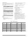
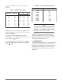
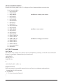
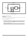
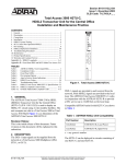
4. DEPLOYMENT GUIDELINES
The ADTRAN HDSL2 system is designed to provide
DS1-based services over loops designed to comply
with carrier service area (CSA) guidelines. CSA
deployment guidelines are given below.
1. All loops are nonloaded only.
2. For loops with 26-AWG cable, the maximum
loop length including bridged tap lengths is 9 kft.
3. For loops with 24-AWG cable, the maximum
loop length including bridged tap lengths is
12 kft.
4. Any single bridged tap is limited to 2 kft.
5. Total bridged tap length is limited to 2.5 kft.
6. The total length of multigauge cable containing
26-AWG cable must not exceed the following:
12 - {(3*L26)/(9 - LBTAP} (in kft.)
L26 = total length of 26-AWG cable
excluding bridged taps (in kft.)
LBTAP = total length of all bridged taps (in kft.)
324 mA
125 mA
6W
3W
+5 V
-48 V Switch battery
Power consumption
Power dissipation
This deployment criteria is summarized in the chart
shown in Figure 4.
11
INVALID CABLE LENGTHS
10
TOTAL
9
BRIDGED
2.5
8
2.0
TAP
1.5
1.0
LENGTH
0.5
7
(KFT)
0.0
6
5
4
3
2
VALID CABLE LENGTHS
1
0
0
1
2
3
4
5
6
7
8
9
WORKING LENGTH OF 26 GAUGE CABLE (KFT)
Figure 4. Deployment Guidelines
Table 9. Worksheet PW-1 Factors
Configuration
ADTRAN Litespan H2TU-R
8
A Column Factor
B Column Factor
C Column Factor
D Column Factor
0.324
NA
NA
0.125
61221002L2-5B
Loop loss per kft for other wire is summarized in
Table 11.
Table 12. Loop Insertion Loss Data
Frequency (Hz)
Table 11. HDSL2 Loss Values
Temperature (°F)
90°
120°
Cable Type
68°
26
PIC
3.902
4.051
4.253
26
24
Pulp
PIC
4.030
2.863
4.179
2.957
4.381
3.083
24
22
Pulp
PIC
3.159
2.198
3.257
2.255
3.391
2.333
22
19
Pulp
PIC
2.483
1.551
2.450
1.587
2.629
1.634
19
Pulp
1.817
1.856
1.909
Cable Gauge
Table 12 provides the recommended maximum local
loop loss information for PIC cable at 70ºF, 135 ohms,
resistive termination.
An approximation for the maximum amount of
wideband noise on an HDSL2 local loop as measured
by a 50 kb filter is < 31 dBrn.
An approximation for the maximum level of impulse
noise as measured using a 50 kb filter on an HDSL2
loop is < 50 dBrn.
61221002L2-5B
3,000
10,000
50,000
100,000
150,000
196,000
200,000
250,000
325,000
Maximum Loss (dB)
12.0
15.0
25.5
30.0
32.75
35.0
35.25
37.50
42.00
NOTE
These approximations are to be used as guidelines
only and may vary slightly on different loops.
Adhering to the guidelines should produce
performance in excess of 10-7 BER.
For further information regarding deployment
guidelines, and applications, reference ADTRAN’s
Supplemental Deployment Information for HDSLx,
document P/N 61221HDSLL1-10.
5. MAINTENANCE
The ADTRAN Litespan H2TU-C requires no routine
maintenance. ADTRAN does not recommend that
repairs be performed in the field. Repair services may
be obtained by returning the defective unit to the
ADTRAN Customer and Product Service (CAPS)
department.
9
6. TROUBLESHOOTING PROCEDURES
Table 13 is a troubleshooting guide for the Litespan
H2TU-C.
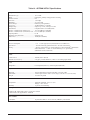
7. PRODUCT SPECIFICATIONS
Product specifications for the ADTRAN H2TU-C are
listed in Table 14.
8. WARRANTY AND CUSTOMER SERVICE
ADTRAN will replace or repair this product within
the warranty period if it does not meet its published
specifications or fails while in service. Warranty
information can be found at
www.adtran.com/warranty.
U.S. and Canada customers can also receive a copy of
the warranty via ADTRAN’s toll-free faxback server
at 877-457-5007.
• Request Document 414 for the U.S. and Canada
Carrier Networks Equipment Warranty.
• Request Document 901 for the U.S. and Canada
Enterprise Networks Equipment Warranty.
Refer to the following subsections for sales, support,
CAPS requests, or further information.
ADTRAN Sales
Pricing/Availability:
800-827-0807
ADTRAN Technical Support
Pre-Sales Applications/Post-Sales Technical Assistance:
800-726-8663
Standard hours: Monday - Friday, 7 a.m. - 7 p.m. CST
Emergency hours: 7 days/week, 24 hours/day
ADTRAN Repair/CAPS
Return for Repair/Upgrade:
(256) 963-8722
Repair and Return Address
Contact Customer and Product Service (CAPS) prior
to returning equipment to ADTRAN.
ADTRAN, Inc.
CAPS Department
901 Explorer Boulevard
Huntsville, Alabama 35806-2807
Table 13. Troubleshooting Guide
Condition
Solution
At power up, all front panel
indicators are OFF
1. Verify that the channel bank or ONU BPS power LEDs are on.
2. Make sure that the unit is fully and correctly inserted into the channel bank or ONU.
3. If step 1 fails, contact Alcatel customer service (800-848-0333). If step 1 passes, but step
2 fails, replace the H2TU-C.
The STAT LED remains RED.
1. Verify that the channel bank or ONU BPS STAT LEDs are off.
2. Verify that the equipment type for the Litespan H2TU-C slot is AHDSL2. Using TL1,
equipment type is shown with the command RTRV-EQPT::AID, where AID is the access
identifier (i.e., COT-1-15).
3. If step 1 fails, contact Alcatel customer service (800-848-0333). If step 1 and step 2 pass,
replace the H2TU-C. If step 1 passes but step 2 fails, delete the equipment record
(i.e., DLT-EQPT::COT-1-15 with TL1) and reinsert the card, or equip the slot with the
currently reserved equipment type.
The STAT LED is OFF, but the
HLOS LED remains RED
.
1. Confirm that the HDSL2 loop is not open.
2. Confirm that the HDSL2 loop is not shorted.
3. Verify the loop conforms to CSA guidelines and is not too long. Loop loss at 200 kHz
should be less than 35.25 dB.
4. Verify that the HDSL2 loop has acceptable noise limits (see Section 4).
5. Verify that tip and ring of the HDSL2 loop belong to the same twisted pair.
6. If steps 1 through 5 pass, but the HLOS LED remains red, replace the H2TU-C.
7. If step 6 fails, replace the H2TU-R.
The STAT LED is OFF, but the
RLOS LED remains RED.
1. Check that the framing and line coding are set appropriately for T1 data at the H2TU-R and
check for cross-connected T1 data coming to the H2TU-C.
2. Check that the RLOS LED at the H2TU-R is off.
3. If step 1 fails, change the appropriate framing and line coding. If step 1 passes but step 2 fails,
a problem may exist at the H2TU-R T1 interface. If subsequent testing determines that the
problem does not exist at the T1interface, replace the H2TU-C.
10
61221002L2-5B
Table 14. ADTRAN H2TU-C Specifications
Loop Interface
Modulation Type ............................................... 16 TC PAM
Mode .................................................................. Full duplex, partially overlapped echo canceling
Number of Pairs ................................................ One
Line Rate ........................................................... 1.552 mbps
Baud Rate .......................................................... 517.333 k baud
Service Range..................................................... Defined by CSA guidelines
Loop Loss .......................................................... 35 dB maximum @ 196 kHz
Bridged Taps ..................................................... Single Taps < 2 kft., total taps ≤2.5 kft.
Performance ...................................................... Compliant with T1.418-2000 (draft)
H2TU-C Transmit Power (Data) Level ............. 16.6 ±0.5 dBm (0 to 450 kHz)
H2TU-C Transmit Power (Activation) Level ... 16.3 ±0.5 dBm (0 to 350 kHz)
Input Impedance ................................................ 135 Ω
Maximum Loop Resistance ............................... 900 Ω per span
Return Loss ....................................................... 12 dB (50 to 200 kHz)
Power
Power Consumption ........................................... +5 V: 1.7 watts typical; 48 V (includes H2TU-C and H2TU-R)
Span Power ......................................................... –190 VDC internally generated from the –48 VDC switch battery
Fusing ................................................................. –48 VDC (switch battery) is current-limited by a 500 mA Slo-Blo® subminiature
surface-mount fuse. +5 VDC is current-limited by a 3 A quick-acting
subminiature surface-mount fuse.
Clock
Clock Sources .................................................... Internal, DSX-1 derived
Internal Clock Accuracy .................................... ± 25 ppm, (exceeds Stratum 4). Meets T1.101 timing requirements
Tests
Diagnostics ........................................................ Local loopback (H2TU-C), remote loopback (H2TU-R)
Physical
Mounting ............................................................ Litespan 2000 CBA, Litespan 2012 CBA, or an ONU CBA
Dimensions ......................................................... 4.42 in. high x 0.84 in. wide x 10.4 in. deep (11.22 cm x 2.13 cm x 26.4 cm)
Weight ................................................................ Less than one pound
Environment
Temperature ....................................................... Operating (standard): –40°C to +70°C
Storage: –40°C to 85°C
Humidity ............................................................ Up to 95% noncondensing
Compliance
Bellcore GR-1089-CORE (Class 2), ANSI T1.418-2002
NRTL listed to the applicable UL standards
Part Number
1221002L2 ......................................................... Asynchronous H2TU-C Line Card Unit (AHDSL2), Narrowband
61221002L2-5B
11
This page is intentionally blank.
12
61221002L2-5B
Appendix A
HDSL2 Loopbacks
HDSL MAINTENANCE MODES
This appendix describes operation of the HDSL2
system with regard to detection of in-band and ESF
facility data link loopback codes.
Upon deactivation of a loopback, the HDSL2 system
will synchronize automatically.
Loopback Process Description
In general, the loopback process for the HDSL2
system elements is modeled on the corresponding
DS1 system process. Specifically, the H2TU-C
loopback is similar to an Intelligent Office Repeater
loopback and the H2TU-R loopbacks are similar to a
T1 NIU.
Loopback Control Codes
A summary of control sequences is given in Table
A-1.
NOTE
In all control code sequences presented, the
in-band codes are shown left-most bit transmitted
first, and the ESF data link codes with right-most
bit transmitted first.
The unit can detect the loopback activation or
deactivation code sequence only if an error rate of
1E-03 or greater is present.
61221002L2-5B
A-1
Table A-1. In-Band Addressable Loopback Codes
Function
Code
Response
1 in 31
100
Loop down everything.
1 in 6 1
100000
Loopback at the H2TU-R toward the network; must be armed before
initiated.
4 in 7
1111000
Loopback data from network toward network in the H2TU-C.
6 in 7
1111110
Loopback data from customer toward customer in H2TU-C.
FF1E
1111 1111 0001
1110
Loopback data from network toward network at H2TU-C.
3F1E
0011 1111 0001
1110
Loopback data from customer toward customer at H2TU-C.
Arm1 (also known
as 2-in-5 pattern)
11000
If the pattern is sent from the network, the units will arm and the H2TU-R
will loop up toward the network. No AIS or errors will be sent as a result
of this loopback. If the pattern is sent from the customer, all units will
arm.
Arm (ESF Data
Link)
FF48
1111 1111 0100
1000
If the pattern is sent from the network, the units will arm and an H2TU-R
network loopback will be activated. This code has no functionality when
sent from the customer.
Disarm1 (in-band)
(also known as
3-in-5 pattern)
11100
When sent from the network or customer, all units are removed from the
armed state and loopbacks will be released. If any of the units are in
loopback when the 11100 pattern is received, they will loop down. The
LBK LEDs will turn off on all units.
Disarm1
(ESF Data Link)
FF24
1111 1111 0010
0100
When sent from the network or customer, all units are removed from the
armed state and loopbacks will be released.
H2TU-C Network
Loop Up1, 2
D3D3
1101 0011 1101
0011
If the units have been armed and no units are in loopback*, the H2TU-C
will loop up, 2 seconds of AIS (all ones) will be transmitted, the looped
data will be sent for 5 seconds, and then a burst of 231 logic errors will be
injected. The burst of 231 logic errors will continue every 20 seconds as
long as the D3D3 pattern is detected. When the pattern is removed, the
unit will remain in loopback. If the pattern is re-instated, the injection of
231 logic errors will continue every 20 seconds. If the pattern is sent from
the network, the loop up and error injection will be toward the network. If
the pattern is sent from the customer, the loopback and error injection will
be toward the customer.
H2TU-R Address
20 for extended
demarc1
C754
1100 0111 0101
0100
When sent from the customer, an H2TU-R network loopback is activated
and a 200-bit error confirmation is sent. Two seconds of AIS (all ones)
will be sent, 5 seconds of data will pass, and then 200 bit errors will be
injected into the DSX-1 signal. As long as the pattern continues to be sent,
200 errors will be injected every 20 seconds. The HDSL2 office unit will
not block transmission of far end NIU loopback from the customer premise
(H2TU-R).
Note: All codes listed above must be sent for a minimum of 5 seconds in order for them to be detected and acted upon.
* If NIU is enabled, then the H2TU-R can be in network loopback when the H2TU-C loop up codes are sent.
1
The H2TU-C and H2TU-R individually detect and act upon in-band loopback control codes. Depending on which list number of
H2TU-R is used with the Litespan H2TU-C, some of these control codes may not cause action (such as loop up, error injection, etc.) at the H2TU-R.
Refer to the H2TU-R documentation for supported control codes.
2
Units must be armed with 11000b or FF48h before this code will work
3
In order to behave like a NIU, the H2TU-R will not loop down from the network side with 9393h.
4
This code will be detected only if the units are armed OR if any loopbacks are active.
A-2
61221002L2-5B
Table A-1. In-Band Addressable Loopback Codes (Continued)
Function
Code
Response
Loop down1, 3
9393
1001 0011 1001
0011
When sent from the network or customer, all units currently in loopback
will loop down. Armed units will not disarm. In order to behave like a
smartjack, the H2TU-R will not loop down from a network loopback in
response to the 9393 pattern if NIU Loopback is enabled.
Query Loopback1, 2
D5D5
1101 0101 1101
0101
When the pattern is sent from the network, logic errors will be injected
towards the network to indicate a loopback is present toward the network.
When the pattern is sent from the customer, logic errors will be injected
towards the customer to indicate a loopback is present toward the
customer. The number of errors injected is determined by the nearest unit
that is in loopback. As long as the pattern continues to be sent, errors are
injected again every 20 seconds (H2TU-C = 231 errors), (H2TU-R = 20
errors).
Query Loop
Parameters2
DBDB
1101 1011 1101
1011
If the H2TU-C is in network loopback and armed, logic errors are injected
towards the network upon detection of the DBDB pattern from the
network. As long as the pattern continues to be sent, errors are injected
again every 20 seconds. The number of errors injected each time depends
on the current status of signal margin and pulse attenuation parameters on
each loop.
If all HDSL2 receiver points (H2TU-C and H2TU-R) indicate pulse
attenuation ≤ 30 dB and signal quality (margin) ≥ 6 dB, 111 errors are
injected every 20 seconds; otherwise, 11 errors are injected every 20
seconds. This pattern has no functionality when sent from the customer.
Loopback Time
Out Override1, 2, 4
D5D6
1101 0101 1101
0110
If the units are armed or a unit is currently in loopback when this pattern is
sent from the network or customer, the loopback time out override feature
will automatically disable loopback time out. In other words, the loopback
will not time out due to the current loopback time out option setting. As
long as the units remain armed, the time out will remain disabled. When
the units are disarmed, the loopback time out will revert to the previous
loopback time out setting.
Span Power
Disable1, 2, 4
6767
0110 0111 0110
0111
If the units are armed and 6767 is sent from the network or customer, the
H2TU-C will disable span power, turning off the H2TU-R. If the pattern is
sent from the network, the span power will be disabled as long 6767
pattern is detected. Once the pattern is no longer received, the H2TU-C
will reactivate span power. All units will then retrain and return to the
disarmed and unlooped state. If the pattern is sent from the customer, the
span power will only be disabled momentarily.
Note: All codes listed above must be sent for a minimum of 5 seconds in order for them to be detected and acted upon.
* If NIU is enabled, then the H2TU-R can be in network loopback when the H2TU-C loop up codes are sent.
1
The H2TU-C and H2TU-R individually detect and act upon in-band loopback control codes. Depending on which list number of H2TU-R is used with
the Litespan H2TU-C, some of these control codes may not cause action (such as loop up, error injection, etc.) at the H2TU-R. Refer to the H2TU-R
documentation for supported control codes.
2
Units must be armed with 11000b or FF48h before this code will work.
3
In order to behave like a NIU, the H2TU-R will not loop down from the network side with 9393h.
4
This code will be detected only if the units are armed OR if any loopbacks are active.
61221002L2-5B
A-3
This page is intentionally blank.
A-4
61221002L2-5B
Appendix B
TL1 H2TU-C Tutorial
GENERAL
This appendix is intended to highlight the necessary menus/commands needed to provision the ADTRAN
H2TU-C card. A more detailed explanation of shelf specific items may be found in the Alcatel TL1 Reference
Practice, OSP-363-205-502.
Logging into the TL1 command screens is accomplished by entering the following:
ACT-USER::<userid>:::<password>
If the login is successful, the following complied message will display:
M
0
COMPLD
NOTE
To view the help file, enter “?” (question mark) at any time.
NOTE
Commands may be entered at any point by typing them in directly, without having to navigate to sub-menus.
After first logging in, enter “?” to display the Main Menu. The Main Menu will display the following available
sub-menus:
MAIN MENU
1. Administration Menu
2. Maintenance Menu
3. Provisioning Menu
4. Testing Menu
5. LOGOFF
NOTE
Items in bold text indicate menu items of interest for AHDSL2.
61221002L2-5B
B-1
MAINTENANCE MENU AND ASSOCIATED SUB-MENUS
From the Main Menu, enter “2” to display the Maintenance Menu as shown below.
Maintenance Menu
1. ADSL Maintenance Menu
2. ATM Maintenance Menu
3. EC1 Maintenance Menu
4. Equipment Maintenance Menu
5. External Controls Menu
6. HDSL Maintenance Menu
7. Interface Group Maintenance Menu
8. LINK Maintenance Menu
9. OPR-ACO-COM
10. OSI Maintenance Menu
11. RTRV-ALM-ALL
12. RTRV-COND-ALL
13. RTRV-LOG-ALM
14. RTRV-ROUTE-T0
15. SHDSL Maintenance Menu
16. SONET Maintenance Menu
17. STARSPAN Maintenance Menu
18. T0 Maintenance Menu
19. T0TS Maintenance Menu
20. T1 Maintenance Menu
21. T3 Maintenance Menu
22. Timing Maintenance Menu
23. X25 Maintenance Menu
B. Main Menu
M. Main Menu
B-2
← Item of interest for the H2TU-C
← Item of interest for the H2TU-C
61221002L2-5B
HDSL MAINTENANCE MENU
From the Maintenance Menu, enter “6” to display the HDSL Maintenance Menu as shown below.
HDSL Maintenance Menu
1. ALW-MSG-HDSL
2. INH-MSG-HDSL
3. RMV-HDSL
4. RST-HDSL
5. RTRV-ALM-HDSL
6. RTRV-ATTR-HDSL
7. RTRV-COND-HDSL
8. SET-ATTR-HDSL
B. Maintenance Menu
M. Main Menu
← Retrieve existing HDSL alarms for the H2TU-C
RTRV-ALM-HDSL Command
Input Format
The RTRV-ALM-HDSL command is used to retrieve existing HDSL alarms for the H2TU-C card.
<RTRV-ALM-HDSL
AID[ALL]= RT-1-21
NTFCNCDE[ALL]= CR, MJ, MN, NR
CONDTYPE[ALL]= MSGLOST, LOSW, DCCONT,
T-SNRL, INCRAI-CI, T-LA
SRVEFF[ALL]= NSA, SA
← Severity of alarm to retrieve
← Alarms available to retrieve
← Can choose between non-service affecting NSA and
service affecting SA
Additional HDSL Maintenance Commands
The following commands are not listed in the Maintenance Menu, but are available for execution.
INIT-REG-HDSL Command
Input Format
The INIT-REG-HDSL command is used to clear the HDSL PM data for the H2TU-C card.
<INIT-REG-HDSL
AID[ALL]= RT-1-21
MONTYPE[ALL]= ES, SES, UAS, MS, LA, SNRMIN
LOCN[]= NEND, FEND,
TMPER[]= 1-DAY, 15-MIN,
← Slot of interest
← PM parameters that can be cleared
← Location to clear
← Time periods available to clear
RTRV-PM-HDSL Command
Input Format
The RTRV-PM-HDSL command is used to retrieve HDSL PM data for the H2TU-C card.
<RTRV-PM-HDSL
AID[ALL]= RT-1-21
MONTYPE[ALL]= ES, SES, UAS, MS, LA, SNRMIN
LOCN[]= NEND, FEND,
TMPER[]= 1-DAY, 15-MIN,
61221002L2-5B
← Slot of interest
← PM parameter to retrieve
← Location to retrieve
← Time periods available to retrieve
B-3
T1 MAINTENANCE MENU
From the Maintenance Menu, enter “20” to display the T1 Maintenance Menu as shown below.
T1 Maintenance Menu
1. ALW-MSG-T1
2. ALW-SW-T1
3. CONN-JACK-T1
4. DISC-JACK-T1
5. INIT-REG-T1
6. INH-MSG-T1
7. INH-SW-T1
8. OPR-PROTNSW-T1
9. RLS-PROTNSW-T1
10. RMV-T1
11. RST-T1
12. RTRV-ALM-T1
13. RTRV-ATTR-T1
14. RTRV-COND-T1
15. RTRV-PM-T1
16. SET-ATTR-T1
B. Maintenance Menu
M. Main Menu
← Clears the T1 PM data for the H2TU-C
← Retrieve T1 PM data for the H2TU-C
INIT-REG-T1 Command
Input Format
The INIT-REG-T1 command is used to clear T1 PM data for the H2TU-C card.
<INIT-REG-T1
← Slot of interest
AID[ALL]= RT-1-21
MONTYPE[ALL]= MS, CVL, ESL, SESL, UASL, B8ZSSL, PDVSL
← Location to clear
LOCN[]= NEND, FEND,
← Time periods available to clear
TMPER[]= 1-DAY, 1-HR,
RTRV-PM-T1 Command
Input Format
The RTRV-PM-T1 command is used to retrieve T1 PM data for the H2TU-C card.
<RTRV-PM-T1
← Slot of interest
AID[ALL]= RT-1-21
MONTYPE[ALL]= MS, CVL, ESL, SESL, UASL, B8ZSSL, PDVSL
← Time periods available to retrieve
TMPER[]= 1-DAY, 1-HR,
MONDAT[]= Up to 2/8 days of PM data history depending upon facility. MM-DD && MD
MONTM[]= Up to 8/24 hours of PM data history depending upon facility. HH-MM && M
B-4
61221002L2-5B
PROVISIONING MENU
From the Main Menu, enter “3” to display the Provisioning Menu as shown below.
Provisioning Menu
1. ADSL Provisioning Menu
2. Cross-Connection Menu
3. EC1 Provisioning Menu
4. Equipment Provisioning Menu
5. Ethernet Provisioning Menu
6. HDSL Provisioning Menu
7. Interface Group Provisioning Menu
8. Link Provisioning Menu
9. OSI Provisioning Menu
10. SHDSL Provisioning Menu
11. SONET Provisioning Menu
12. STARSPAN Provisioning Menu
13. T0 Provisioning Menu
14. T0TS Provisioning Menu
15. T1 Provisioning Menu
16. T3 Provisioning Menu
17. Timing Source Provisioning Menu
18. X25 Provisioning Menu
B. Main Menu
M. Main Menu
61221002L2-5B
← Item of interest for the H2TU-C
← Item of interest for the H2TU-C
← Item of interest for the H2TU-C
B-5
CROSS-CONNECTION MENU
From the Provisioning Menu, enter “2” to display the Cross-Connection Menu as shown below.
Cross-Connection Menu
1. DLT-CRS-STS1
2. DLT-CRS-T0
3. DLT-CRS-T1
4. DLT-CRS-T3
5. DLT-CRS-VC
6. DLT-CRS-VP
7. ED-CRS-STS1
8. ED-CRS-T0
9. ED-CRS-T3
10. ENT-CRS-STS1
11. ENT-CRS-T0
12. ENT-CRS-T1
13. ENT-CRS-T3
14. ENT-CRS-VC
15. ENT-CRS-VP
16. RTRV-CRS-STS1
17. RTRV-CRS-T0
18. RTRV-CRS-T1
19. RTRV-CRS-T3
20. RTRV-CRS-VC
21. RTRV-CRS-VP
B. Provisioning Menu
M. Main Menu
← Delete an existing cross-connect
← Enter a cross-connect
← Retrieve existing cross-connects
DLT-CRS-T1 Command
Input Format
The deletion of any existing cross-connects may be accomplished by selecting “3” from the Cross-Connection
Menu or by entering the command directly as shown below.
<DLT-CRS-T1
FROM[]= RT-1-1
TO[]= RT-1-21;
or
<DLT-CRS-T1::RT-1-1,RT-1-21;
Response Format
If the cross-connect is successfully removed, the user will receive an indication as shown below.
Litespan2000 02-02-20 14:10:00
M 0 COMPLD
/* 1 T1 Cross-Connection Deleted */
;
<
B-6
61221002L2-5B
ENT-CRS-T1 Command
Input Format
The choice to enter cross-connects may be accomplished either by selecting “12” from the Cross-Connection
Menu or by entering the command directly as shown in the example below where a cross-connect is initiated
between slot 1 and slot 21.
<ENT-CRS-T1
FROM[]= RT-1-1
TO[]= RT-1-21.
or
<ENT-CRS-T1::RT-1-1,RT-1-21;
NOTE
A command that is typed directly can be entered from any level (menu or sub-menu).
Response Format
The user should receive a complied message such as the one below to indicate that the cross-connect was
successfully initiated.
Litespan2000 02-02-20 14:11:23
M 0 COMPLD
“RT-1-1,RT-1-21”
/* 1 T1 Cross-Connection Entered */
;
<
RTRV-CRS-T1 Command
Input Fomrat
Retrieving existing cross-connect status may be accomplished either by selecting “18” from the
Cross-Connection Menu or by entering the command directly as shown in the example below.
<RTRV-CRS-T1
AID[ALL]= RT-1-1;
or
<RTRV-CRS-T1::RT-1-1;
Response Format
If a cross-connect exists at the indicated slot, the user will see an indication of the slots involved in the crossconnect as shown below.
Litespan2000 02-02-20 14:12:18
M 0 COMPLD
“RT-1-1,RT-1-21:::IS-NR,CRS”
/* 1 T1 Cross-Connection Retrieved */
;
<
61221002L2-5B
B-7
HDSL PROVISIONING MENU
From the Provisioning Menu, enter “6” to display the HDSL Provisioning Menu as shown below.
HDSL Provisioning Menu
1. DLT-HDSL
2. ED-HDSL
3. ENT-HDSL
4. RTRV-HDSL
5. DLT-GOS-HDSL
6. ED-GOS-HDSL
7. ENT-GOS-HDSL
8. RTRV-GOS-HDSL
B. Provisioning Menu
M. Main Menu
← Edit HDSL provisioning parameters for the H2TU-C
← Edit the HDSL Grade of Service tables in the shelf
ED-HDSL Commands
Input Format
HDSL configuration parameters may be changed by selecting “2” from the HDSL Provisioning Menu or by
entering the ED-HDSL commands directly as shown below.
<ED-HDSL
NOTE
Items in braces { } are the available selections for the specified parameter.
<ED-HDSL
FT1MODE[]= {NO | YES};
or
<ED-HDSL::RT-1-21:::: FT1MODE ={NO | YES};
<ED-HDSL
LP[]= {SINK | SOURCE};
or
<ED-HDSL::RT-1-21:::: LP ={SINK | SOURCE};
<ED-HDSL
LPBKACTC[]={0000000000000000 | 0000000000000001 | 0000000000000010 | 0000000000000011 };
or
<ED-HDSL::RT-1-21:::: LPBKACTC ={0000000000000000 | 0000000000000001 | 0000000000000010 |
0000000000000011 };
B-8
61221002L2-5B
<ED-HDSL
LPBKACTR[]={0000000000000000 | 0000000000000001};
or
<ED-HDSL::RT-1-21:::: LPBKACTR ={0000000000000000 | 0000000000000001};
<ED-HDSL
LPBKDEACTCDE[]={0000000000000000 | 0000000000000001 | 0000000000000010};
or
<ED-HDSL::RT-1-21:::: LPBKDEACTCDE ={0000000000000000 | 0000000000000001 | 0000000000000010};
<ED-HDSL
LPBKTMO[]= {0 | 20 | 60 | 120 };
or
<ED-HDSL::RT-1-21:::: LPBKTMO ={0 | 20 | 60 | 120};
<ED-HDSL
NIDLPBK[]= {NO | YES};
or
<ED-HDSL::RT-1-21:::: NIDLPBK ={NO | YES};
<ED-HDSL
NTWKKPALV[]= {NO | YES};
or
<ED-HDSL::RT-1-21:::: NTWKKPALV ={NO | YES};
ED-GOS-HDSL Command
Input Format
HDSL configuration parameters for the Grade of Service tables may be changed by entering the ED-GOS-HDSL
commands directly as shown below.
<ED-GOS-HDSL
AID[]=
MONTYPE[]= ES, SES, UAS, LA, SNR, CV
THLEV[]= Each montype has its level
TMPER[]= 1-DAY, 15-MIN,
← Grade of Service table of interest
← Threshold level for the particular monitored type
← Time periods setting for the indicated monitored
type and level
61221002L2-5B
B-9
Grade of Service tables allow the user to set performance monitoring threshold levels for various alarms/event
conditions. There are 15 GOS tables available for each type of service (in our case T1 and HDSL).
Example: The HDSL GOS1 may contain a loop attenuation threshold setting of 30 (dB) while HDSL GOS2
contains a loop attenuation threshold setting of 25. (Each GOS table can be edited by the user but it will affect all
slots that are provisioned to use the edited GOS table.)
Using the ED-HDSL command, the user can select GOS=1 or 2 depending on whether they want the shelf to
alarm or report the loop attenuation threshold crossing at 30 dB or 25 dB.
T1 PROVISIONING MENU
From the Provisioning menu, enter “15” to display to the T1 Provisioning Menu as shown below.
T1 Provisioning Menu
1. DLT-GOS-T1
2. DLT-T1
3. ED-GOS-T1
4. ED-T1
5. ENT-GOS-T1
6. ENT-T1
7. RTRV-GOS-T1
8. RTRV-T1
B. Provisioning Menu
M. Main Menu
← Edit the T1 Grade of Service tables in the shelf
← Edit T1 provisioning parameters for the H2TU-C
ED-GOS-T1 Command
Input Format
T1 Grade of Service parameters may be changed by selecting “3” from the T1 Provisioning Menu or by entering
the ED-GOS-T1 command as shown below.
<ED-GOS-T1
← Grade of Service table of interest
AID[]=
MONTYPE[]= CVL, ESL, SESL, UASL, B8ZSSL, PDVSL
← Threshold level for the particular monitered type
THLEV[]= Each montype has its level
← Time periods setting for the indicated monitered type
TMPER[]= 1-DAY, 1-HR,
and level
ED-T1 Commands
Input Format
T1 configuration parameters may be changed by selecting “4” from the T1 Provisioning Menu or by entering the
ED-T1 command as shown below.
<ED-T1
AT[]={0 | 15.0 | 7.5};
or
<ED-T1::RT-1-21::::AT={0 | 15.0 | 7.5};
NOTE
For framing format (FMT) changes the card must first have its service state changed to OOS.
B-10
61221002L2-5B
<ED-T1
FMT[]={ESF | SF | UNFR | AUTO};
or
<ED-T1::RT-1-21::::FMT={ESF | SF | UNFR | AUTO};
<ED-T1
LINECDE[]= {AMI | B8ZS};
or
<ED-T1::RT-1-21::::LINECDE={AMI | B8ZS};
TESTING MENU
From the Main Menu, enter “4” to display the Testing Menu as shown below.
Testing Menu
1. OPR-LPBK-HDSL
2. OPR-LPBK-OC12
3. OPR-LPBK-OC3
4. OPR-LPBK-T0
5. OPR-LPBK-T0TS
6. OPR-LPBK-T1
7. OPR-LPBK-T3
8. RLS-LPBK-HDSL
9. RLS-LPBK-OC12
10. RLS-LPBK-OC3
11. RLS-LPBK-T0
12. RLS-LPBK-T0TS
13. RLS-LPBK-T1
14. RLS-LPBK-T3
B. Main Menu
M. Main Menu
61221002L2-5B
← Enable a loopback
← Remove a loopback
B-11
NOTE
Prior to entering any loopback command, the line card must be removed from service.
Remove card from service = RMV-HDSL;
H2TU-C Network Loopback
Loop up command = OPR-LPBK-HDSL::RT-1-21-C:::NEND;
Loop down command = RLS-LPBK-HDSL::RT-1-21-C:::NEND;
H2TU-C Customer Loopback
Loop up command = OPR-LPBK-HDSL::RT-1-21-C:::FEND;
Loop down command = RLS-LPBK-HDSL::RT-1-21-C:::FEND;
H2TU-R Network Loopback
Loop up command = OPR-LPBK-HDSL::RT-1-21-R:::NEND;
Loop down command = RLS-LPBK-HDSL::RT-1-21-R:::NEND;
H2TU-R Customer Loopback
Loop up command = OPR-LPBK-HDSL::RT-1-21-R:::FEND;
Loop down command = RLS-LPBK-HDSL::RT-1-21-R:::FEND;
Upon completion of loopback testing, return the card to service.
Restore card to service = RST-HDSL;
B-12
61221002L2-5B
Appendix C
Metallic Test Access Unit (MTAU) Testing Capabilities
This appendix describes the testing functionality available for the ADTRAN H2TU-C card via the MTAU unit.
For a complete description of the MTAU unit refer to Alcatel document Common Equipment Unit Descriptions,
OSP 363-405-250.
NOTE
The functionality of the SPLIT and MON features detailed in this document supercedes that shown in the OSP
363-405-250.
INITIATING MTAU TEST ACCESS
CONN-JACK-T1
The Connect T1 Jack command connects a T1 or HDSL facility to the MTAU via the channel bank test bus.
Input Format: CONN-JACK-T1:<TID>:<AID>:<CTAG>::<MD>;
AID = Access ID of the unit to be connected to the MTAU
MD = Mode (SPLIT or MON)
Example: CONN-JACK-T1::COT-1-15:::SPLIT;
NOTE
To use SPLIT mode, a facility must be out of service for maintenance or out of service for memory
administration.
Diagrams of the functionality of the two modes are shown below:
SPLIT Mode
Used to test toward the network equipment and to test the loops
AHDSL2
Alcatel
Network
Equip
Tip
A-3
Test
LIU
HDSL2
Transceiver
HDSL2 Loop
Ring1
A-4
TAE, RAE
TBE, RBE
EQPT jacks on the MTAU
TAF RAF
Facility jack on the MTAU
Figure C-1. SPLIT Mode
61221002L2-5B
C-1
MON Mode
Used to test toward the remote customer equipment
AHDSL2
Tip
A-3
Alcatel
Network
Equip
Test
LIU
HDSL2
Transceiver
HDSL2 Loop
Ring1
A-4
TAE, RAE
TBE, RBE
EQPT jacks on the MTAU
Figure C-2. MON Mode
REMOVAL OF MTAU TEST ACCESS
DISC-JACK-T1
The Disconnect T1 Jack command disconnects a T1 or HDSL facility from the metallic test access unit (MTAU).
Input Format: DISC-JACK-T1:<TID>:<AID>:<CTAG>;
Example:
DISC-JACK-T1::COT-1-15;
NOTE
AIDs of T1 or HDSL facilities currently connected can be determined using the
RTRV-STATUS-MTAU command.
C-2
61221002L2-5B