1
Cisco 7000 Hardware
Installation and Maintenance
Corporate Headquarters
170 W. Tasman Drive
San Jose, CA 95134-1706
USA
408 526-4000
800 553-NETS
Customer Order Number: DOC-7000IM3
Cisco Document Assembly Number: 83-0096-01
Text Part Number: 78-1037-05
The products and specifications, configurations, and other technical information regarding the products contained in this manual are subject to change
without notice. All statements, technical information, and recommendations contained in this manual are believed to be accurate and reliable but are
presented without warranty of any kind, express or implied, and users must take full responsibility for their application of any products specified in this
manual.
This equipment generates, uses, and can radiate radio frequency energy and, if not installed and used in accordance with the instruction manual for this
device, may cause interference to radio communications. This equipment has been tested and found to comply with the limits for a Class A computing device
pursuant to Subpart J of Part 15 of FCC Rules, which are designed to provide reasonable protection against such interference when operated in a commercial
environment. Operation of this equipment in a residential area is likely to cause interference, in which case users at their own expense will be required to
take whatever measures may be required to correct the interference.
The following third-party software may be included with your product and will be subject to the software license agreement:
CiscoWorks software and documentation are based in part on HP OpenView under license from the Hewlett-Packard Company. HP OpenView is a
trademark of the Hewlett-Packard Company. Copyright 1992, 1993 Hewlett-Packard Company.
The Cisco implementation of TCP header compression is an adaptation of a program developed by the University of California, Berkeley (UCB) as part of
UCB’s public domain version of the UNIX operating system. All rights reserved. Copyright © 1981, Regents of the University of California.
Network Time Protocol (NTP). Copyright © 1992, David L. Mills. The University of Delaware makes no representations about the suitability of this
software for any purpose.
Point-to-Point Protocol. Copyright © 1989, Carnegie-Mellon University. All rights reserved. The name of the University may not be used to endorse or
promote products derived from this software without specific prior written permission.
The Cisco implementation of TN3270 is an adaptation of the tn3270, curses, and termcap programs developed by the University of California, Berkeley
(UCB) as part of UCB’s public domain version of the UNIX operating system. All rights reserved. Copyright © 1981-1988, Regents of the University of
California.
Cisco incorporates Fastmac software in some Token Ring products. Fastmac software is licensed to Cisco by Madge Networks Limited.
XRemote is a trademark of Network Computing Devices, Inc. Copyright © 1989, Network Computing Devices, Inc., Mountain View, California. NCD
makes no representations about the suitability of this software for any purpose.
The X Window System is a trademark of the Massachusetts Institute of Technology. Copyright © 1987, Digital Equipment Corporation, Maynard,
Massachusetts, and the Massachusetts Institute of Technology, Cambridge, Massachusetts. All rights reserved.
THIS MANUAL AND THE SOFTWARE OF THE ABOVE-LISTED SUPPLIERS ARE PROVIDED “AS IS” WITH ALL FAULTS. CISCO AND THE
ABOVE-NAMED SUPPLIERS DISCLAIM ALL WARRANTIES, EXPRESSED OR IMPLIED, INCLUDING THOSE OF MERCHANTABILITY AND
FITNESS FOR A PARTICULAR PURPOSE OR ARISING FROM A COURSE OF DEALING, USAGE, OR TRADE PRACTICE.
IN NO EVENT SHALL CISCO OR ITS SUPPLIERS BE LIABLE FOR ANY INDIRECT, SPECIAL, CONSEQUENTIAL, OR INCIDENTAL
DAMAGES, INCLUDING, WITHOUT LIMITATION, LOST PROFITS OR LOSS OR DAMAGE TO DATA ARISING OUT OF THE USE OR
INABILITY TO USE THIS MANUAL, EVEN IF CISCO HAS BEEN ADVISED OF THE POSSIBILITY OF SUCH DAMAGES.
Notice of Restricted Rights:
Use, duplication, or disclosure by the Government is subject to restrictions as set forth in subparagraph (c) of the Commercial Computer Software Restricted Rights clause at FAR §52.227-19 and subparagraph (c)(1)(ii) of the Rights in Technical Data and Computer Software clause at DFARS §252.2277013. The information in this manual is subject to change without notice.
AccessPath, AtmDirector, Browse with Me, CCIP, CCSI, CD-PAC, CiscoLink, the Cisco Powered Network logo, Cisco Systems Networking
Academy, the Cisco Systems Networking Academy logo, Fast Step, Follow Me Browsing, FormShare, FrameShare, GigaStack, IGX, Internet
Quotient, IP/VC, iQ Breakthrough, iQ Expertise, iQ FastTrack, the iQ Logo, iQ Net Readiness Scorecard, MGX, the Networkers logo, Packet,
RateMUX, ScriptBuilder, ScriptShare, SlideCast, SMARTnet, TransPath, Unity, Voice LAN, Wavelength Router, and WebViewer are trademarks
of Cisco Systems, Inc.; Changing the Way We Work, Live, Play, and Learn, Discover All That’s Possible, and Empowering the Internet Generation,
are service marks of Cisco Systems, Inc.; and Aironet, ASIST, BPX, Catalyst, CCDA, CCDP, CCIE, CCNA, CCNP, Cisco, the Cisco Certified
Internetwork Expert logo, Cisco IOS, the Cisco IOS logo, Cisco Press, Cisco Systems, Cisco Systems Capital, the Cisco Systems logo, Enterprise/
Solver, EtherChannel, EtherSwitch, FastHub, FastSwitch, IOS, IP/TV, LightStream, MICA, Network Registrar, PIX, Post-Routing, Pre-Routing,
Registrar, StrataView Plus, Stratm, SwitchProbe, TeleRouter, and VCO are registered trademarks of Cisco Systems, Inc. and/or its affiliates in the
U.S. and certain other countries.
All other trademarks mentioned in this document or Web site are the property of their respective owners. The use of the word partner does not imply
a partnership relationship between Cisco and any other company. (0108R)
Cisco 7000 Hardware Installation and Maintenance
Copyright © 1993–1995, 2001 Cisco Systems, Inc.
All rights reserved. Printed in USA.
SOFTWARE LICENSE
READ THIS SOFTWARE LICENSE AGREEMENT CAREFULLY BEFORE USING THE SOFTWARE.
PLEASE READ THESE TERMS AND CONDITIONS CAREFULLY BEFORE USING THE SOFTWARE. BY USING THE SOFTWARE OF CISCO
SYSTEMS, INC. AND ITS SUPPLIERS FROM TIME TO TIME, YOU AGREE TO BE BOUND BY THE TERMS AND CONDITIONS OF THIS
LICENSE. IF YOU DO NOT AGREE WITH THE TERMS OF THIS LICENSE, PROMPTLY RETURN THE UNUSED SOFTWARE, MANUAL, AND
RELATED EQUIPMENT (WITH PROOF OF PAYMENT) TO THE PLACE OF PURCHASE FOR A FULL REFUND.
Cisco Systems, Inc. (“Cisco”) grants to Customer (“Customer”) a nonexclusive and nontransferable license to use the Cisco software (“Software”) in object
code form solely on a single central processing unit owned or leased by Customer or otherwise embedded in equipment provided by Cisco. Customer may
make one (1) archival copy of the software provided Customer affixes to such copy all copyright, confidentiality, and proprietary notices that appear on the
original.
EXCEPT AS EXPRESSLY AUTHORIZED ABOVE, CUSTOMER SHALL NOT: COPY, IN WHOLE OR IN PART, SOFTWARE OR
DOCUMENTATION; MODIFY THE SOFTWARE; REVERSE COMPILE OR REVERSE ASSEMBLE ALL OR ANY PORTION OF THE
SOFTWARE; OR RENT, LEASE, DISTRIBUTE, SELL, OR CREATE DERIVATIVE WORKS OF THE SOFTWARE.
Customer agrees that aspects of the licensed materials, including the specific design and structure of individual programs, constitute trade secrets and/or
copyrighted material of Cisco. Customer agrees not to disclose, provide, or otherwise make available such trade secrets or copyrighted material in any form
to any third party without the prior consent of Cisco. Customer agrees to implement reasonable security measures to protect such trade secrets and
copyrighted material. Title to Software and documentation shall remain solely with Cisco.
LIMITED WARRANTY. Cisco warrants that the Software will substantially conform to the published specifications for such Software, if used properly in
accordance with the Documentation, for a period of ninety (90) days from the date of shipment. To be eligible for a remedy, Customer must report all
warranted problems within the warranty period to the party that supplied the Product to Customer or to the Cisco Service Partner if the Software was exported
under the multinational uplift program. Cisco's sole and exclusive obligation and Customer's exclusive remedy with respect to nonconforming Software
upon contact will be, at Cisco's option and potentially through the Sales or Service Partner, either (i) to provide a correction or a workaround for any
reproducible errors, or (ii) to refund to Customer the license fee for the Software in the event that a license fee was paid and the other remedy is not available,
or, if the license fee was zero, refund the price of the hardware less depreciation calculated on a straight-line basis. Customer agrees to cooperate with Cisco
or its Sales or Service Partner in creating the environment in which the error occurred. Further, Customer agrees to supply any necessary equipment for such
tests.
This Limited Warranty does not apply to Software which (1) has been altered, except as authorized by Cisco, (2) has not been installed, operated, repaired,
or maintained in accordance with any installation, handling, maintenance, or operating instructions supplied by Cisco, (3) has been subjected to unusual
physical or electrical stress, misuse, negligence, or accident, (4) is used in ultrahazardous activities, (5) has been used in such a way that Cisco or its Sales
Partner cannot reasonably reproduce the Software error, (6) has been exported from the original country of destination without payment of an uplift, or (7)
has been misapplied. In no event does Cisco warrant that the Software is error free or that Customer will be able to operate its networks without problems
or interruptions.
DISCLAIMER. THIS WARRANTY IS IN LIEU OF AND CISCO DISCLAIMS ALL OTHER WARRANTIES AND CONDITIONS, EXPRESSED OR
IMPLIED, INCLUDING THOSE OF MERCHANTABILITY, NONINFRINGEMENT, AND FITNESS FOR A PARTICULAR PURPOSE.
CONSEQUENTIAL DAMAGES. IN NO EVENT SHALL CISCO OR ITS SUPPLIERS BE LIABLE FOR ANY INDIRECT, SPECIAL,
CONSEQUENTIAL, OR INCIDENTAL DAMAGES INCLUDING, WITHOUT LIMITATION, LOST PROFITS OR LOSS OR DAMAGE TO DATA
ARISING OUT OF THE USE OR INABILITY TO USE THIS CISCO SOFTWARE, EVEN IF CISCO HAS BEEN ADVISED OF THE POSSIBILITY
OF SUCH DAMAGES. SOME STATES DO NOT ALLOW LIMITATION OR EXCLUSION OF LIABILITY FOR CONSEQUENTIAL OR
INCIDENTAL DAMAGES.
Customer will comply with all applicable export laws and regulations if it exports the products. This restriction shall survive termination of this Agreement.
This License is effective until terminated. Customer may terminate this License at any time by destroying the software together with all copies thereof. Cisco
may immediately terminate this License if the Customer fails to comply with any term or condition hereof. Upon any termination of this License, Customer
shall discontinue use of the Software and shall destroy all copies of the software.
This License shall be governed by and construed in accordance with the laws of the State of California. If any portion hereof is found to be void or
unenforceable, the remaining provisions of this License shall remain in full force and effect. This License constitutes the entire License between the parties
with respect to the use of the Software.
Restricted Rights - Cisco’s software and supporting documentation are provided with RESTRICTED RIGHTS. Use, duplication, or disclosure by the
Government is subject to the restrictions as set forth in subparagraph (c) of the Commercial Computer Software - Restricted Rights clause at FAR §52.22719 and subparagraph (c)(1)(ii) of The Rights in Technical Data and Computer Software clause at DFARS §52.227-7013.
HARDWARE WARRANTY
Performance Warranty. Cisco warrants to Customer, for a period of ninety (90) days from the shipping date, that Hardware purchased under this Agreement
will be free from hardware defects in material and workmanship. To be eligible for a remedy, Customer must report all warranted problems within the
warranty period to the party that supplied the Product to Customer or to the Cisco Service Partner if the Hardware was exported under the multinational
uplift program.
Hardware Remedies. In the event of a warranted problem with respect to the Hardware, Customer must contact the place it acquired the Hardware or the
Cisco Service Partner if the Hardware was exported pursuant to the multinational uplift program as soon as possible after it becomes aware of the defect.
Cisco or the Sales or Service Partner (as appropriate) will supply replacement parts for the products listed in Cisco's recommended spares list. Replacement
parts will be shipped within five (5) working days after receipt of Customer's request. Cisco or its Sales or Service Partner will bear the cost for shipment
of advance replacements to Customer. Customer must return all defective boards and assemblies prior to installation of the replacement boards and
assemblies to Cisco or the Sales or Service Partner in accordance with the then-current return material authorization (RMA) procedures. Cisco's sole and
exclusive obligation with respect to defective Hardware will be, at Cisco's option and through a Sales or Service Partner if necessary, to either (i) provide
advance replacement service as described above, (ii) replace the Product with a Product that does not contain the defect, or (iii) refund the price paid for the
Hardware less depreciation calculated on a straight-line basis.
Exclusions. The above warranty does not apply to any Product which (1) has been altered, except as authorized by Cisco, (2) has not been installed, operated,
repaired, or maintained in accordance with any installation, handling, maintenance, or operating instructions supplied by Cisco, (3) has been subjected to
unusual physical or electrical stress, misuse, negligence, or accident, (4) is used in ultrahazardous activities, (5) has been used in such a way that Cisco cannot
reasonably reproduce the Software error, or (6) has been exported from the original country of destination without payment of an uplift. In no event does
Cisco warrant that Customer will be able to operate its networks without problems or interruptions.
DISCLAIMER. THIS WARRANTY IS IN LIEU OF AND CISCO DISCLAIMS ALL OTHER WARRANTIES AND CONDITIONS, EXPRESSED OR
IMPLIED, INCLUDING THOSE OF MERCHANTABILITY, NONINFRINGEMENT, AND FITNESS FOR A PARTICULAR PURPOSE.
CONSEQUENTIAL DAMAGES. IN NO EVENT SHALL CISCO OR ITS SUPPLIERS BE LIABLE FOR ANY INDIRECT, SPECIAL,
CONSEQUENTIAL, OR INCIDENTAL DAMAGES INCLUDING, WITHOUT LIMITATION, LOST PROFITS OR LOSS OR DAMAGE TO DATA
ARISING OUT OF THE USE OR INABILITY TO USE THIS CISCO SOFTWARE, EVEN IF CISCO HAS BEEN ADVISED OF THE POSSIBILITY
OF SUCH DAMAGES. SOME STATES DO NOT ALLOW LIMITATION OR EXCLUSION OF LIABILITY FOR CONSEQUENTIAL OR
INCIDENTAL DAMAGES.
Document Objectives
Audience
Chapter 1
xiii
xiii
Document Organization
xiv
Document Conventions
xv
Product Overview
17
Physical Description 18
Chassis Specifications 20
System Backplane 21
Arbiter 23
Power Supplies 24
System Blower 26
Route Processor (RP) 26
Memory Components 27
Jumpers 30
LEDs 31
Serial Ports 31
7000 Series Route Switch Processor (RSP7000) 31
Memory Components 33
System Software 34
Jumpers 35
LEDs 35
Serial Ports 35
7000 Series Chassis Interface (RSP7000CI) 35
Switch Processor (SP) 36
Silicon Switch Processor (SSP) 37
Interface Processors 38
ATM Interface Processor (AIP) 39
Channel Interface Processor (CIP) 40
Ethernet Interface Processor (EIP) 41
Fast Ethernet Interface Processor 42
Token Ring Interface Processor (TRIP) 43
FDDI Interface Processor (FIP) 44
Fast Serial Interface Processor (FSIP) 46
Serial Port Adapters 49
E1-G.703/G.704 Port Adapter 50
HSSI Interface Processor (HIP) 51
MultiChannel Interface Processor (MIP) 53
Functional Overview 54
Port Densities 54
Port Addresses 54
Physical Interface Addresses 55
MAC Address Allocator 56
Online Insertion and Removal (OIR) 57
Microcode 58
Redundant Power 61
Environmental Monitoring and Reporting Functions
Environmental Monitoring 62
61
Contents i
Environmental Reports
Chapter 2
Preparing for Installation
63
67
Safety Recommendations 68
Lifting the Router Safely 68
Working with Electricity 69
Preventing Electrostatic Discharge Damage
70
Site Requirements 71
AC and DC Power 71
Plant Wiring 72
Interference Considerations 72
Distance Limitations 72
HSSI Connections 80
Equipment Racks 80
Site Environment 82
Preventive Site Configuration: Maintaining Normal Operation
General Precautions 83
Equipment-Rack Ventilation 84
Power 84
Preparing Network Connections 84
Additional and Optional Connection Equipment 84
AIP Interface Types 86
Channel Attachment Connection Equipment 90
Ethernet Connection Equipment 90
Fast Ethernet Connection Equipment 93
Token Ring Connection Equipment 93
Token Ring Physical Connections 94
Token Ring Fault Management 96
FDDI Connection Equipment 97
FDDI Media 97
FDDI Transceivers and Cable Connectors 98
FDDI Station Descriptions 99
MultiChannel (MIP) Connection Equipment 102
Serial Connection Equipment 103
Universal Serial Cables 103
E1-G.703/G.704 Cables 104
NRZ and NRZI Formats 105
Cyclic Redundancy Checks (CRCs) 105
Signal Modes and Timing 106
EIA/TIA-232 Connections 107
EIA/TIA-449 Connections 107
V.35 Connections 108
X.21 Connections 108
EIA-530 Connections 108
HSSI Connection Equipment 109
Console and Auxiliary Port Connection Equipment 110
ii
Tools for Installation
110
Installation Checklist
111
Cisco 7000 Hardware Installation and Maintenence
83
Checking the Contents 111
System Components 111
Site Log
112
Port Configuration Worksheet
Site Log
Chapter 3
115
116
Installing the Router
117
Rack-Mounting the Router
General Installation
117
118
Installing Power Supplies 119
Tools Required 119
Accessing the Bays 120
Inserting Power Supplies 121
Connecting AC and DC Power 122
Connecting Interface Cables 124
External Cabling Guidelines 124
ATM Connections 125
Channel Attachment Connections 128
Ethernet Connections 128
Fast Ethernet Connections 129
Token Ring Connections 130
FDDI Connections 130
Single Attachment Connections 131
Dual Attachment Connections 133
Installing an Optical Bypass Switch 135
Serial Connections 137
HSSI Connections 139
MultiChannel Connections 140
Connecting the Console Terminal 140
Connecting Auxiliary Port Equipment 141
Starting the Router
141
Using the Flash Memory Card 143
Installing and Removing the Flash Memory Card 143
Formatting the Flash Memory Card 145
Copying an Image into the Flash Memory Card 146
Making the Flash Memory Card Image Bootable 148
Enabling Booting from the Flash Memory Card 148
Copying to the Flash Memory Card 149
Recovering from Locked Blocks 149
Flash Memory Card Compatibility 150
Chapter 4
Troubleshooting the Installation
151
Troubleshooting Overview 152
Problem Solving with Subsystems 152
Identifying Startup Problems 152
Troubleshooting the Power Subsystem 154
Contents iii
Troubleshooting the RP Subsystem 155
Troubleshooting the SP (or SSP) and Interface Processor Subsystem
Chapter 5
Maintenance
157
Installing and Configuring Processor Modules 158
Online Insertion and Removal Information 158
Tools Required 159
Ejector Levers 160
Removing and Replacing the RP, SP, SSP, RSP7000, or RSP7000CI
Removing CxBus Interface Processors 162
Installing CxBus Interface Processors 162
Sample Screen Display for OIR 164
Microcode Component Replacement 164
Tools Required 166
Replacing the ROM 166
Verifying the Microcode Version 167
RP and RSP7000 Configurations 168
Configuring Jumpers 168
Software Configuration Register 173
Saving and Retrieving the Configuration File 181
Copying the Configuration File 183
Retrieving the Configuration File 185
Copying Files Between NVRAM and a Flash Memory Card 186
Replacing System Software EPROMs 188
Replacing RP SIMMs (Upgrading DRAM) 190
Replacing RSP7000 SIMMs (Upgrading DRAM) 195
Replacing RSP7000 DRAM SIMMs 200
Removing SIMMs 202
Installing New SIMMs 203
FSIP Configurations 205
Configuring Timing (Clock) Signals 206
Configuring NRZI Format 207
Configuring 32-Bit Cyclic Redundancy Check (CRC) 207
Configuring 4-Bit Cyclic Redundancy Check 208
Replacing Port Adapter Cables 208
Replacing Serial Port Adapters 210
MIP Configurations 216
Configuring the Interfaces 216
Checking the Configuration 221
Removing and Replacing MIP Port Adapters 225
Installing and Replacing Power Supplies
Tools Required 230
Installing Power Supplies 230
Removing Power Supplies 230
229
Removing and Replacing the Front Chassis Panels
Tools Required 233
Removing the Panels 233
Replacing the Panels 235
Cleaning and Replacing the Air Filter
iv
155
Cisco 7000 Hardware Installation and Maintenence
237
233
161
Tools Required 237
Accessing and Cleaning or Replacing the Filter
237
Replacing Internal Components 238
Replacing the LED Board 238
Tools Required 239
Removing the LED Board 240
Installing a New LED Board 241
Installation Checkout 241
Replacing the Chassis Blower 242
Tools Required 243
Removing the Blower 243
Installing a New Blower 244
Installation Checkout 245
Replacing the Arbiter Board 246
Tools Required 246
Removing the Arbiter Board 246
Installing a New Arbiter Board 247
Installation Checkout 247
Appendix A
Cabling Specifications
Console Port Signals
249
250
Auxiliary Port Signals
250
Ethernet Connector Signals
250
Fast Ethernet Connector Signals
Token Ring Port Signals
251
252
FDDI Optical Bypass Switch Signals
Serial Adapter Cable Pinouts
253
253
HSSI Connector Signals 259
HSSI Interface Cable 259
Null Modem Cable 260
MIP Interface Cable Pinouts
Appendix B
Reading LED Indicators
Front Panel LEDs
RP LEDs
263
263
Power Supply LEDs
SP and SSP LEDs
261
264
265
266
RSP7000 LEDs
267
Interface Processor LEDs
AIP LEDs 268
CIP LEDs 269
EIP LEDs
271
FEIP LEDs 272
268
Contents v
FIP LEDs 273
FSIP LEDs 275
HIP LEDs 277
MIP LEDs 278
TRIP LEDs 279
Appendix C
vi
Industry-Standard Wiring Plans
Cisco 7000 Hardware Installation and Maintenence
281
Contents vii
viii
Cisco 7000 Hardware Installation and Maintenence
Contents ix
x
Cisco 7000 Hardware Installation and Maintenence
Contents xi
xii
Cisco 7000 Hardware Installation and Maintenence
About This Manual
This section discusses the objectives, intended audience, and organization of this hardware
installation and maintenance publication, and defines the conventions used to convey instructions
and noteworthy information.
Document Objectives
This publication contains two kinds of procedures: specific procedures for preparing your site and
network equipment for the initial hardware installation of the router, and procedures you may need
in the future to modify or upgrade your system. It will guide you through the initial site preparation,
hardware installation, and startup of your new router. After you install the hardware, you will use the
appropriate companion publications to configure your system. The maintenance chapter provides
maintenance requirements and guidelines for the general care and upkeep of your new router. All
additions or upgrades to the router hardware, software, or microcode (firmware) that you order from
the factory are accompanied by configuration notes that provide product-specific installation
instructions and up-to-date product information.
All Cisco technical documentation and selected marketing materials are available on UniverCD,
Cisco’s online library of product information. UniverCD us updated and shipped monthly, so it may
be more up to date than printed documentation. UniverCD is available both as a single CD and as an
annual subscription. To order UniverCD, contact your local sales representative or call Customer
Service.
Audience
Setting up and maintaining a network requires the knowledge and expertise of people with a variety
of skills. In many cases, the people responsible for installing and maintaining hardware and wiring
are not the ones who configure the software and administer the network. This publication provides
information specific to installing and maintaining the router hardware. To use this publication, you
should be familiar with electronic circuitry and wiring practices, and preferably have experience as
an electronic or electromechanical technician. Although this document provides brief descriptions
and examples of a few software configuration and display commands, it is not a reference for
software. For comprehensive descriptions and examples of software configuration commands and
the procedures for implementing them, refer to the related software configuration and reference
documentation.
About This Manual xiii
Document Organization
Document Organization
The organization of this publication follows a recommended linear installation sequence: starting
with Chapter 1, “Product Overview,” and continuing through Chapter 3, “Installing the Router.” You
will refer to Chapter 4, “Troubleshooting,” only if you experience problems with the initial hardware
installation or startup. Use the maintenance information in Chapter 5, “Maintenance,” whenever you
add, upgrade, or rearrange system components.
This publication also includes some information that you may not need at initial installation, but is
useful when upgrading or adding components to the system. Additional reference information is
included in the appendixes. Following is a brief description of each chapter:
•
Chapter 1, “Product Overview,” describes the physical properties of the router chassis,
components, and interface options. It also provides brief functional descriptions of the primary
system features.
•
Chapter 2, “Preparing for Installation,” is a preparatory section that describes site requirements,
safety considerations, tools required, optional and required network connection equipment,
unpacking checklists, and procedures you should perform before actual installation. This chapter
contains descriptions and illustrations of all types of network interface cables, connectors, and
interface devices that you may need for your network connections, so you can use this chapter as
a reference.
•
Chapter 3, “Installing the Router,” provides instructions for rack mounting the router, installing
power supplies, connecting the external network interface cables, and starting the system. After
your system successfully initializes, you will proceed to the related software documentation to
configure the interfaces. If the system fails to initialize successfully, you will proceed to
Chapter 4 to troubleshoot the problem.
•
Chapter 4, “Troubleshooting the Installation,” provides troubleshooting guidelines for the initial
hardware installation and suggests steps to help you quickly isolate the source and resolve the
problem.
•
Chapter 5, “Maintenance,” provides procedures for replacing the system components, for adding
new components, and for upgrading or modify the existing components.
•
Appendix A, “Cabling Specifications,” lists pin signals for the network interface cables you will
need and provides cable assembly drawings for the serial port adapter cables.
•
Appendix B, “Reading LED Indicators,” describes the various states and indications of the LEDs
on the chassis front panel, route processor (RP), switch processor (SP), and the various interface
processors. This information is of limited use at initial system startup because the interfaces are
not yet configured, and most of the LEDs are not functional (although they may light). This
information is provided for your reference, to be used after the interfaces have been configured
and brought on line.
•
Appendix C, “Industry Standard Wiring Plans,” lists the telephone industry color-code scheme
for 25-pair wires including the pin numbers
xiv Cisco 7000 Hardware Installation and Maintenance
Document Conventions
Document Conventions
This publication uses the following conventions:
•
The symbol ^ represents the key labeled Control.
For example, the key combination ^z means hold down the Control key while you press the z key.
•
Cross references to additional or related information within this publication specify the title (in
quotes) of the section that contains the information. For example, refer to “Document
Conventions.”
Command descriptions use these conventions:
•
Examples that contain system prompts denote interactive sessions, indicating the commands that
you should enter at the prompt. The system prompt indicates the current level of the EXEC
command interpreter. For example, the prompt router> indicates that you should be at the user
level, and the prompt router# indicates that you should be at the privileged level. Access to the
privileged level usually requires a password. Refer to the related software configuration and
reference documentation for additional information.
•
•
•
•
Commands and keywords are in boldface font.
Arguments for which you supply values are in italic font.
Elements in square brackets ([ ]) are optional.
Alternative but required keywords are grouped in braces ({ }) and separated by vertical bars (|).
Examples use these conventions:
•
•
•
•
•
Terminal sessions and sample console screen displays are in screen font.
Information you enter is in boldface screen font.
Nonprinting characters, such as passwords, are in angle brackets (< >).
Default responses to system prompts are in square brackets ([ ]).
Exclamation points (!) at the beginning of a line indicate a comment line.
Caution Means reader be careful. You are capable of doing something that might result in
equipment damage or loss of data.
Note Means reader take note. Notes contain helpful suggestions or references to materials not
contained in this manual.
Timesaver Means the described action saves time. You can save time by performing the action
described in the paragraph.
Warning Means danger. You are in a situation that could cause bodily injury. Before you work on
any equipment, be aware of the hazards involved with electrical circuitry and standard practices for
preventing accidents. Chapter 2 provides general safety considerations and specific guidelines for
safely installing the Cisco 7000 router.
About This Manual xv
Document Conventions
xvi Cisco 7000 Hardware Installation and Maintenance
CHAP TER
1
Product Overview
The Cisco 7000 is the top-of-the-line Cisco 7000 series router/bridge that provides high reliability,
availability, serviceability, and performance. The system supports multiprotocol, multimedia routing
and bridging with a wide variety of protocols and any combination of Ethernet, Fast Ethernet, Token
Ring, Fiber Distributed Data Interface (FDDI), serial, multichannel channel attachment, and
High-Speed Serial Interface (HSSI) media. Network interfaces reside on modular interface
processors, which provide a direct connection between the high-speed Cisco Extended Bus (CxBus)
and the external networks.
Online insertion and removal (OIR) allows you to add, replace, or remove interface processors
without interrupting the system power or entering any console commands. The redundant power
option provides dual load-sharing power supplies that maintain input power without interruption if
one supply fails. Environmental monitoring and reporting functions enable you to maintain normal
system operation by resolving adverse environmental conditions prior to loss of operation. If
conditions reach critical thresholds, the system shuts down to avoid equipment damage from
excessive heat or electrical current. Downloadable software and microcode allow you to load new
images into Flash memory remotely, without having to physically access the router, for fast, reliable
system upgrades.
This chapter provides physical and functional overviews to familiarize you with your new system. It
contains physical descriptions of the system hardware and major components, and functional
descriptions of hardware-related features. Descriptions and examples of software commands appear
only when they are necessary for installing or maintaining the system hardware. For complete
command descriptions and instructions, refer to the related software reference publications.
Following is a list of acronyms that identify the system components and features:
•
•
•
•
•
•
•
CxBus—Cisco Extended Bus, 533-megabits-per-second (Mbps) data bus for interface processors
•
•
•
FSIP—Fast Serial Interface Processor
AIP—Asynchronous Transfer Mode (ATM) Interface Processor
CIP—Channel Interface Processor
EIP—Ethernet Interface Processor
FEIP—Fast Ethernet Interface Processor
FIP—FDDI (Fiber Distributed Data Interface) Interface processor
FRU—Field-replaceable unit (as opposed to a spare) can only be replaced by a Cisco certified
technician. The arbiter board is categorized as an FRU.
HIP—High-Speed Serial Interface (HSSI) Interface Processor
MIP—MultiChannel Interface Processor
Product Overview 1-17
Physical Description
•
OIR—Online insertion and removal, the feature that allows you to replace interface processors
and redundant power supplies without interrupting system power
•
•
•
•
•
•
•
PA—Port adapter, for example the FSIP or MP daughter card
RP—Route Processor, the system processor board
RSP7000—7000 Series Route Switch Processor
RSP7000CI—7000 Series Chassis Interface
SP—Switch Processor, the CxBus traffic controller
SSP—Silicon Switch Processor, the CxBus traffic controller
TRIP—Token Ring Interface Processor
Physical Description
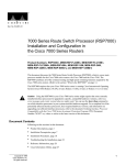
The router front panel, shown in Figure 1-1, contains three status indicators and two removable
panels for access to the internal components. The three-light emitting diodes (LEDs) on the front
panel indicate normal system operation and the currently active power supplies. On the back of the
router, additional LEDs on the RP and power supplies indicate the same status. The normal LED
lights to indicate that the system is in a normal operating state. The upper power and lower power
LEDs light to indicate that a power supply is installed in the indicated power supply bay and is
providing power to the system. The power LEDs go out if the power supply in the corresponding bay
reaches an out-of-tolerance temperature or voltage condition. (For descriptions of thresholds and
status levels, refer to the section “Environmental Monitoring and Reporting Functions” in this
chapter.) The front panel normal LED is controlled by the RP, which contains an identical normal
LED that can be seen from the rear of the router.
Figure 1-1
Router Front View
Cisco 7000
LOWER
POWER
NORMAL
UPPER
POWER
LOWER
POWER
NORMAL
H1316a
UPPER
POWER
1-18 Cisco 7000 Hardware Installation and Maintenance
Physical Description
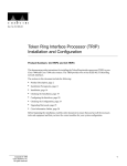
The rear of the router, shown in Figure 1-2, provides access to the seven interface slots and
removable power supplies. The lower power supply bay contains the first (standard equipment)
power supply, and the upper bay contains the second power supply (optional equipment in systems
with redundant power). The interface slots contain the RP, the SP (or the SSP) and up to five network
interface processors. When viewing the router from the rear, the RP is always located in the far right
slot (the RP slot), and the SP (or SSP) is always located in the adjacent slot (the SP slot). The
remaining five slots are numbered 0 through 4 from left to right. The five interface processor slots
support any combination of network interface types: Ethernet, Token Ring, FDDI, serial, channel
attachment, and HSSI. The RP, SP (or SSP), and interface processors are keyed with guides on the
backplane to prevent them from being fully inserted in the wrong slot.
The RP, SP, SSP, and interface processors are described in the sections that follow.
Figure 1-2
Router Rear View
Captive
installation screw
DC
AC
FA
IL
PO
WE
R
Upper
power supply
I
O
Captive
installation screw
DC
AC
FA
IL
PO
WE
H2358
R
Lower
power supply
I
O
Slot 0
1
2
3
4
SP RP
or
slot
SSP
slot
Product Overview 1-19
Physical Description
The RP, SSP (or SP), and interface processors (collectively referred to as processor modules) slide
into slots in the rear of the router and connect directly to the backplane; there are no internal cables
to connect. Spring-loaded ejector levers help to ensure that a processor module is either fully
connected to the backplane or fully disconnected from it. Captive installation screws at the top and
bottom of each processor module faceplate also ensure proper seating in the backplane, and prevent
the processor module from disengaging from the backplane. (The system will hang if a processor
module pulls away from the backplane and breaks the connection between the processor module
connector and the backplane pins.) Empty slots contain a blank board carrier (an interface processor
carrier without a board, LEDs, or connectors) to maintain proper airflow through the chassis.
One 700-watt (W) power supply is standard equipment in the router. A second, identical power
supply provides a redundant power option. Load sharing and redundancy are automatically enabled
when a second power supply is installed; no configuration is required. Each supply has an individual
power switch and status LEDs. When only one power supply is used, it should be installed in the
bottom power supply bay to maintain a low center of gravity in the router chassis.
Chassis Specifications
The system physical specifications and power requirements are listed in Table 1-1.
Table 1-1
Router Physical Specifications
Description
Specifications
High-speed backplane
533-Mbps (megabits per second) CxBus, 7 slots
Dimensions (H x W x D)
19.25 x 17.5 x 25.1" (48.90 x 44.45 x 63.75 cm)
Chassis depth including power cord is 28" (71.12 cm)
Weight
Chassis only: 76 lb (34.47 kg)
Chassis fully configured with 1 RP, 1 SP (or SSP), 5 interface processors,
and 2 power supplies: 145 lb (65.76 kg)
DC-input voltage
–40 volts direct current (VDC) minimum
–48 VDC nominal
–72 VDC maximum
DC voltages supplied
and steady state maximum
current ratings
+5.2V @ 100 amps (A)
+12V @ 15A
–12V @ 3A
+24V @ 5A
DC-input power
1000 watts (W)
DC-input power supply
hold-up time specification
10 milliseconds (ms) of output after the input has been interrupted
DC-input wiring
8 AWG (American Wire Gauge) wire that you provide
Power supply
700W maximum (AC-input and DC-input power supplies)
Power dissipation
626W maximum configuration, 530W typical with maximum configuration
Heat dissipation
1200W (4100 Btu/hr)
Input voltage
100 to 240 VAC wide input with power factor corrector (PFC)
Frequency
50 to 60 Hz (hertz) autoranging
AC current rating
12A maximum at 100 VAC, 6A maximum at 240 VAC with the chassis fully configured
Airflow
140 cfm (cubic feet per minute) through the system blower
Operating temperature
32 to 104°F (0 to 40°C)
1-20 Cisco 7000 Hardware Installation and Maintenance
Physical Description
Description
Specifications
Nonoperating temperature
–4 to 149°F (–20 to 65°C)
Humidity
10 to 90%, noncondensing
Agency approvals
Safety: UL 1950, CSA 22.2-950, EN60950, EN41003, AUSTEL TS001, AS/NZS 3260
EMI: FCC Class A, EN55022 Class B, VCCI Class 2
The router operates as either a freestanding or rack-mounted unit. An optional rack-mount kit is
available for mounting the chassis in an EIA-310C standard 19-inch equipment rack. When the
system is not mounted in a rack, place it on the floor or on a sturdy platform.
Warning Do not stack the chassis on any other equipment. If the chassis falls, it can cause severe
bodily injury and equipment damage.
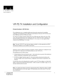
The top-down view of the chassis shown in Figure 1-3 illustrates the locations of the main system
components. The arbiter board (which provides CxBus arbitration), LED board, and system blower
are located inside the left front of the chassis behind removable front panels. The blower moves
cooling air through the chassis and across the RP, SP (or SSP), and interface processors to prevent
components on the boards from overheating. The power-supply bays are located next to interface
processor slot 0 and are accessible from the rear of the chassis. An air dam keeps cooling air drawn
in by the system blower separate from that drawn in by the power-supply fans. (Refer to the section
“Power Supplies” in this chapter.)
System Backplane
The high-speed CxBus transfers information at 533 Mbps. Figure 1-4 shows the basic system
architecture. The RP, which contains the system processor, and the SP (or SSP) provide distributed
processing and control for the interface processors. The SP (or SSP) controls communication
between high-speed CxBus interface processors (interface processor-to-interface processor) and the
system processor (interface processor-to-processor).
Product Overview 1-21
Physical Description
Figure 1-3
Router Chassis, Top-Down View
Cy Bus
backplane
LED
board
System
blower
Processor
slots
Air dam
Air filter
H1328a
Power
supply
bays
Front
of Chassis
Figure 1-4
Rear
of Chassis
Router System Architecture
RP
• 68040 CPU
• Flash EPROM
• 16-MB DRAM
• ENVM Logic
Distributed processing
CxBus EIP
CxBus TRIP
CxBus FIP
CxBus FSIP
CxBus HIP
2/4/6-port Ethernet
interface processor
2/4-port Token Ring
interface processor
Single-port FDDI
interface processor
4/8 port fast serial
interface processor
Single-port HSSI
interface processor
H1351a
SP or SSP
The backplane slots are keyed so that the RP, SP (or SSP), and interface processors can be installed
only in the slots designated for them. Keys on the backplane fit into two key guides on each processor
module. (See Figure 1-5.) While the RP and SP (or SSP) each use unique keys, all five interface
processor slots use the same key, so you can install an interface processor in any interface processor
slot, but not in the RP or SP (or SSP) slots.
1-22 Cisco 7000 Hardware Installation and Maintenance
Physical Description
Caution When installing an RP, SP (or SSP), or interface processor, ensure that you are installing
it in the appropriate slot to avoid damaging the key guides or the backplane.
Figure 1-5
Backplane Slot Keys
Key guides on interface
processors, RP and SP (or SSP)
Top
Interface processor
slots 0–5
Top
key guide
SSP (or SSP)
RP
Rear of
processor card
Bottom
SSP (or SSP)
RP
Bottom
key guide
H3144
Interface processor
slots 0–5
Arbiter
The arbiter, which arbitrates traffic on the CxBus and generates the CxBus clock, is a printed circuit
board that resides on the front of the system backplane inside the front chassis compartment.
(See Figure 1-3.) The arbiter arbitrates traffic across the CxBus by prioritizing access requests from
interface processors to ensure that each request is processed and to prevent any interface processor
from jeopardizing the CxBus and interfering with the ability of the other interface processors to
access the SSP (or SP) and RP. Following is a summary of the services that the arbiter provides:
•
CxBus clock generation—Generates the 16.667-megahertz (MHz) clock and provides a private
copy of the clock to the SP (or SSP) and each interface processor.
•
CxBus arbitration—Arbitrates interface processor requests to transmit commands on the CxBus.
The arbitration is based on a round-robin priority scheme to ensure that all interface processors
have access to a known portion of the CxBus bandwidth.
•
Global lock arbitration—Arbitrates interface processor and SP (or SSP) requests for the global
lock, a synchronization primitive used to control SP (or SSP) and interface processor access to
shared data structures.
The arbiter is a field-replaceable unit (FRU) that is available for immediate onsite replacement if the
existing arbiter fails. The “Maintenance” chapter provides replacement instructions for the arbiter.
In addition, detailed, up-to-date instructions are included with all spares when they are shipped from
the factory.
Product Overview 1-23
Physical Description
Power Supplies
The router comes equipped with one 700W, AC-input or DC-input power supply. An optional second
identical power supply also is available for redundant power. Dual power supplies are automatically
load sharing and redundant, which means a second power supply can be installed or replaced without
interrupting system operation.
To prevent problems, do not mix DC-input and AC-input power supplies in the same
chassis. Your Cisco 7000 must have either DC-input or AC-input power supplies.
Caution
Each power supply should be connected to a separate power source so that, in case of an input power
line or power supply failure, the second power supply maintains uninterrupted system power.
Caution When only one power supply is used, install it in the lower power-supply bay to maintain
a low center of gravity in the chassis.
You must turn the power switch (shown in Figure 1-6) to the off (O) position before you can remove
it from the chassis. When the power supply switch is in the on (|) position, a metal tab on the switch
slides into a slot in the power supply bay to lock the power supply in the chassis. (See Figure 1-6.)
When the switch is in the off (O) position, the tab retracts so that you can slide the power supply out.
Caution Always tighten the captive installation screw at the top of the power supply; it ensures that
the supply is securely seated in the bay and provides proper grounding. (See Figure 1-6.)
Figure 1-6
Power Supply and Status Indicators—AC-Input Power Supply Shown
Captive
installation
screw
DC
AC
IL
FA
R
WE
IL
FA C PO
A
R
WE
DC
PO
LEDs
Power supply
front panel
AC power
receptacle
O
On/off switch
1-24 Cisco 7000 Hardware Installation and Maintenance
H1314a
I
Locking device
Physical Description
Warning To prevent injury, use both hands when installing or removing power supplies. Each
weighs 20 pounds.
On the router front panel, the upper power and lower power LEDs light when the power supply in
the corresponding bay is installed and supplying power to the system. Both the upper and lower
power LEDs should light in systems with redundant power. In addition to the front panel LEDs, each
power supply contains AC power and DC fail LEDs and individual power switches.
The green AC power LED on the power supply indicates that the supply is turned on and is receiving
input power.
The yellow DC fail LED is normally off, but lights if the power supply shuts down for any of the
following reasons:
•
Power-supply DC section failure, which could be caused by loss of power (input line failure or
operator turned off system power) or an actual failure in the power supply
•
Power-supply shutdown, initiated by the power supply because it detected an out-of-tolerance
temperature or voltage condition in the power supply
In systems with a single power supply, and in systems with redundant power when both power
supplies are being shut down, the DC fail LED lights momentarily as the system ramps down, but
goes out when the power supply has completely shut down. In systems with redundant power and
one power supply still active, the DC fail LED on the failed power supply will remain lit (powered
by the active supply).
The DC-input power supply LEDs include the input power LED and the out fail LED (located in the
same place as the two LEDs on the AC-input power supply). The green input power LED is on when
the input power is applied. The yellow out fail LED is normally off, but flashes at power on for a
lamp test.
The out fail LED lights if the power supply shuts down for either of the following reasons:
•
Power supply DC-output failure, which could be caused by loss of DC-input power (input line
failure or operator turned off system power) or an actual failure in the DC-input power supply
•
Power supply shutdown, initiated by the power supply because it detected an out-of-tolerance
temperature or voltage condition in the power supply
The power supplies are self-monitoring. Each supply monitors its own temperature and internal
voltages. For a description of power-supply shutdown conditions and thresholds, refer to the section
“Environmental Monitoring and Reporting Functions” in this chapter.
A modular power cable connects each power supply to the site power source. A cable retention clip
on the power supply AC receptacle prevents the cable from accidentally being pulled out. For
DC-input power supplies, you supply the power cable based on the specifications provided in
Table 1-1. For power supply installation procedures refer to the section “Installing Power Supplies”
in the chapter “Installing the Router.”
Product Overview 1-25
Physical Description
System Blower
The system blower provides cooling air for the RP, SP (or SSP), and interface processors. The blower
is located inside the front chassis compartment as shown in Figure 1-7.
An internal fan in each power supply draws cooling air from the front of the chassis, through the
power supply, and out the back of the chassis. (See Figure 1-7.) An air dam keeps the power-supply
airflow separate from that of the rest of the chassis (which is cooled by the system blower).
Internal Airflow, Top-Down View
SP RP
or
SSP
Figure 1-7
4
System blower
2
3
Air duct
Slot
0
Air dam
Air dam
Power
supplies
H1338a
Air duct
Rear of
chassis
1
Front of
chassis
The blower draws air in through the air filter in the front chassis panel and directs it up through the
floor of the internal slot compartment and over the boards. The exhaust air is forced out the rear of
the chassis above and to each side of the processor slots. Figure 1-7 shows the airflow path. The
blower needs a clean air filter in order to draw in sufficient amounts of cooling air; excessive dust in
the filter will restrict the airflow. Keep the air filter clean and replace it when needed. The
“Maintenance” chapter provides air filter cleaning and replacement procedures.
Sensors on the RP monitor the inlet and internal chassis air temperatures. If the air temperature at
either of the sensors exceeds a desired threshold, the environmental monitor displays warning
messages and can interrupt system operation to protect the system components from possible
damage from excessive heat or electrical current. For specific threshold and status level descriptions,
refer to the section “Environmental Monitoring and Reporting Functions” in this chapter.
Route Processor (RP)
The RP, shown in Figure 1-8, is the main system processor in the router and is installed in the far
right card slot labeled RP. The RP contains the system central processing unit (CPU), the system
software, and most of the system memory components, and it maintains and executes the
management functions that control the system. The RP contains the following components:
•
•
•
25-MHz Motorola MC68040 CPU for processing key functions that are not time-critical
System hardware configuration register for setting default boot instructions
Bank of hardware (MAC-layer) addresses for the interface ports
1-26 Cisco 7000 Hardware Installation and Maintenance
Physical Description
•
Most of the memory components used by the system, including the eight erasable programmable
read-only memory (EPROM) components that contain the default system software
•
Air-temperature sensors for environmental monitoring
In addition to the preceding system components, the RP contains and executes the following
management functions that control the system:
•
•
•
•
Sending and receiving routing protocol updates
Managing tables and caches
Monitoring interface and environmental status
Providing SNMP management and the console/Telnet interface.
Memory Components
Figure 1-8 shows the locations of the various types of memory on the RP, and Table 1-2 lists the
functions of each.
Figure 1-8
Route Processor (RP)
NO
AL
RM
J2, Flash memory
write-protection
jumper
Software memory
EPROMS
NVRAM
Flash memory J3 J4
EPROMS
BO
OT
CP
U
ER
HA
LT
RO
R
Configuration
register
Flash memory
card slot
H1322a
Auxiliary port
Console port
CPU
DRAM
Product Overview 1-27
Physical Description
Table 1-2
Memory
Type
Memory Components
Size
Quantity
Description
Location
8
4-Mb EPROMs
ROM1–ROM8 (see the chapter
“Maintenance”)
16 MB
or
64 MB
4
4-MB SIMMs
SIMMS sockets U35, U36, U58, U59
4
16-MB SIMMs
NVRAM
128 KB
1
128 KB
U120
Onboard Flash
memory
4 MB
16
256-KB Flash memory
components
U14–U17, U27–U30, U45–U48, U60–63
Flash memory
card3
8 or
16 MB
1
PCMCIA Flash memory
card
Flash memory card on faceplate
EEPROM
–
1
Board-specific information,
address allocator
U108
EPROM1
4 Mb
DRAM
2
1. Although these components actually are EPROMs, they are commonly known as the software or boot ROMs.
2. The size (capacity) of the software EPROMs changes as needed to accommodate the size of the system software image.
Releases 9.17(6) and earlier reside on 2 Mb ROMs, Release 9.17(7) resides on 4 Mb ROMs, and the size of future software releases is
likely to increase.
3. Required for downloading software images larger than 4MB (compressed). The Enterprise and the Enterprise and APPN images of
Cisco IOS Release 11.0 and later will require a Flash memory card.
System Software or Boot ROMs
Eight EPROM components contain the default and bootstrap system software. Downloadable
system software and microcode, which the Cisco 7000 supports for most upgrades, allows you to
remotely download, store, and boot from a new image without having to physically access the router.
EPROMs for Software Release 9.17(7) and later also contain the latest microcode version, in
compressed form, for each interface processor. At system startup, an internal system utility scans for
compatibility problems between the installed interface processor types and the bundled microcode
images, then decompresses the images into running random-access memory (RAM). The bundled
microcode images then function the same as images loaded from the microcode ROMs.
It is unlikely that you will ever need to replace the default system software EPROMs. If replacement
is necessary in the future, refer to the section “Microcode Component Replacement” in the chapter
“Maintenance” and to the replacement instructions that accompany the upgrade kit.
DRAM
Support for 64 MB of DRAM (four 16-MB SIMMs) was introduced with Software Releases 9.17(8)
and 9.21(3).
Effective with Software Releases 9.17(8) and 9.21(3), or later, the RP in new systems is available
with 16 MB of DRAM, which is the default, or with 64 MB of DRAM (RP-64MB-OPT). RP spares
are available with the default 16 MB (RP=) or with 64 MB of DRAM (RP-64MB=). In addition, an
upgrade (RP-64MB-U) provides an RP-64MB= as a replacement for earlier RP versions that do not
support 16-MB SIMMs. The upgrade requires that you return your existing RP to the factory and
offers a significant cost savings over the RP-64MB= spare.
If your RP supports 16-MB SIMMs, you can upgrade the DRAM from 16 MB to 64 MB. (Because
8-MB x 9 SIMMs are not available, 32 MB is not an option.) Otherwise, you must replace the entire
RP to increase the amount of DRAM.
1-28 Cisco 7000 Hardware Installation and Maintenance
Physical Description
Only RPs that meet the following prerequisites support the larger (16-MB) SIMMs:
•
If your system contains Software Release 9.17, the minimum requirements are:
— Software Release 9.17(8) (or a later 9.17 image) in ROM
— System Bootstrap Version 4.6(7.3) (or a later 4.6 version)
— RP board revision B0 or later
Note RPs that shipped from the factory with Release 9.17(7) or earlier in ROM do not support
16-MB SIMMs. Software Release 9.17(8), RP board revision B0, and System Bootstrap Version
4.6(7.3) started shipping as the default in March 1994.
•
If your system contains Software Release 9.21, the minimum requirements are:
— Software Release 9.21(3) (or a later 9.21 image) in ROM
— System Bootstrap Version 4.7(2.1) (or a later 4.7 version)
— RP board revision B0 or later
Bootstrap Version 4.6 is used exclusively with Software Release 9.17, and Bootstrap Version 4.7 is
used exclusively with Software Release 9.21. The revision numbers (indicated in parentheses) for
each system bootstrap version are revised independently of other bootstrap versions. Therefore,
4.6(7) can be a later version than 4.7(2).
To verify that your RP supports the larger SIMMs, issue the following commands:
•
Use the show version command to display the system bootstrap version.
7000# show version
GS Software (GS7), Version 9.17(8.1)
Copyright (c) 1986-1994 by cisco Systems, Inc.
Compiled Fri 04-Feb-94
System Bootstrap, Version 4.6(7.3)
If the display indicates that the system bootstrap version is an earlier version of 4.6 than 4.6(7.3),
or an earlier version of 4.7 than 4.7(2.1), your RP will not support 16-MB SIMMs. Contact a
service representative for information about the RP upgrade.
•
Use the show diag slot command to display current hardware and diagnostic information about
the processor installed in the slot you specify. Because the RP always resides in the same (RP)
slot, specify slot 6 for a Cisco 7000 chassis. The third line of the display shows the current
hardware (HW) and board revisions. (Do not confuse the HW revision with the board revision;
you need only verify that the board revision is B0 or later.)
7000# show diag 6
Slot 6:
EEPROM format version 1
Route Processor, HW rev 1.1, board revision B0
Serial number: 00809933 Part number: 73-0877-04
If the display indicates that the RP board revision is earlier than B0, your RP will not support
16-MB SIMMs. Contact a service representative for information about the RP upgrade.
Product Overview 1-29
Physical Description
NVRAM
Nonvolatile random-access memory (NVRAM) stores the system configuration and the
environmental monitoring logs, and is backed up with built-in lithium batteries that retain the
contents for a minimum of five years. When replacing an RP, be sure to back up your configuration
to a remote server so that you can retrieve it later. (See the Timesaver note that follows.)
Timesaver Before replacing an RP, back up the running configuration to a Trivial File Transfer
Protocol (TFTP) file server so that you can later retrieve it. If the configuration is not saved, the entire
configuration will be lost—inside the NVRAM on the removed route processor—and you will have
to reenter it manually. This procedure is not necessary if you are temporarily removing an RP you
will reinstall; lithium batteries retain the configuration in memory until you replace the RP in the
system.
Flash Memory
The Cisco 7000 contains two types of Flash memory: onboard (embedded) and on a (Flash memory)
card that can be optionally installed in a slot on the RP (or RSP7000). The Flash memory card is
required for downloading software images larger than 4 MB (compressed). Cisco IOS Release 11.0
and later require a Flash memory card.
Either the onboard Flash memory (on a SIMM) or the Flash memory card allows you to remotely
load and store multiple Cisco IOS and microcode images. You can download a new image over the
network or from a local server and then add the new image to Flash or replace the existing files. You
can also transfer images between Flash memory cards and the onboard 8-MB Flash memory.
You can then boot routers either manually or automatically from any of the stored images. Flash
memory also functions as a TFTP server to allow other servers to remotely boot from stored images
or to copy them into their own Flash memory. For security of the onboard Flash memory, jumper J2,
which is adjacent to the embedded Flash memory components, provides Flash memory write
protection. (See the section “Jumpers,” which follows.)
The Flash memory card installs in the card slot on the RP (or RSP7000) faceplate. This card is an 8or 16-MB, Intel Series 2+ Flash memory card, which conforms with the Personal Computer Memory
Card International Association (PCMCIA) format. For more information, see the section, “Using the
Flash Memory Card” in the chapter “Installing the Router.”
EEPROM
An electronically erasable programmable read-only memory (EEPROM) component on the RP (and
on the SSP [or SP] and each interface processor) stores board-specific information such as the board
serial number, part number, controller type, hardware revision, and other details unique to each
board. In addition to this standard information, the RP EEPROM also contains an address allocator,
which is a bank of 40 hardware or media access control (MAC)-level addresses, one for each
possible port in the system. For an explanation of the hardware addressing function, refer to the
section “MAC Address Allocator” in this chapter.
Jumpers
The hardware configuration register is a 50-pin jumper block located above the Flash memory card
port when viewing the RP in the orientation shown in Figure 1-8. By installing jumpers on specific
pins you can define system boot instructions, set broadcast addresses and console baud rates, instruct
the router to perform factory diagnostics at startup, and recover from a lost password.
1-30 Cisco 7000 Hardware Installation and Maintenance
Physical Description
Jumper J2, which is located near the configuration register, provides write protection for Flash
memory. (See Figure 1-8.) The jumper is installed on J2 by default, which allows you to write to
Flash memory. When the jumper is removed, Flash memory is read-only; you cannot write to Flash
memory or erase the contents until you replace the jumper.
Jumpers J3 and J4 are set according to the size of the eight system software EPROMs. You need to
reset these jumpers only if you upgrade the system software by replacing the EPROMs instead of
downloading the new image, and if the size (capacity) of the new EPROMs is greater than those you
replace.
For a detailed description of all jumper functions and settings, refer to the section “RP and RSP7000
Configurations” in the chapter “Maintenance.”
LEDs
The three LEDs on the RP indicate the system and RP status. The chassis front panel normal LED
and the RP normal LED are both controlled by the RP and light to indicate that the system is
operational. During normal operation, the CPU halt and boot error LEDs on the RP should be off.
When the system is turned on or restarted, the boot LED goes on for 1 or 2 seconds, then goes off.
The CPU halt LED, which lights only if the system detects a processor hardware failure, should
never be on. For complete descriptions of the LED states, refer to the “Reading LED Indicators”
appendix.
Serial Ports
Two asynchronous serial ports on the RP, the console and auxiliary ports, provide the means for
connecting a terminal, modem, or other device for configuring and managing the system. A data
circuit-terminating equipment (DCE) EIA/TIA-232 receptacle console port on the RP provides a
direct connection for a console terminal. The adjacent data terminal equipment (DTE) EIA/TIA-232
plug auxiliary port supports flow control and is often used to connect a modem, a channel service
unit (CSU), or other optional equipment for Telnet management of the attached device.
Note Prior to acceptance by the Electronic Industries Association (EIA) and Telecommunications
Industry Association (TIA) as a standard, EIA/TIA-232 [or 449] was an EIA recommended standard
(RS) known as RS-232 [or 449].
The two EIA/TIA-232 serial ports on the RP, console and auxiliary, support asynchronous
transmission. Asynchronous transmission uses control bits to indicate the beginning and end of
characters, rather than precise timing. The serial interface ports on the FSIP support synchronous
transmission, which maintains precise clocking between the transmitter and receiver by sending
frames of information that comprise separate clock signals along with the data signals. When
connecting serial devices, ensure that the devices support the proper transmission timing methods
for the respective port: asynchronous for the console and auxiliary ports, and synchronous for the
FSIP serial ports.
7000 Series Route Switch Processor (RSP7000)
The RSP7000 is a new main system processor module for the Cisco 7000 series routers. The
RSP7000 combines all of the switched routing and high-speed switching functions of the separate
Route Processor (RP) and Switch Processor (SP), which are used in the Cisco 7000 series routers,
Product Overview 1-31
Physical Description
but with improved performance on a single processor module. The RSP7000 contains the central
processing unit (CPU) and most of the memory components for the Cisco 7000 series routers. You
must install the RSP7000 in the 7000 RSP slot (slot 5 in the Cisco 7000).
Note The RSP7000 requires that your Cisco 7000 is running Cisco Internetwork Operating System
(Cisco IOS) Release 10.3(9) or later. For the RSP7000 to operate properly, the Cisco 7000 chassis
must also be configured with the 7000 Series Chassis Interface (RSP7000CI), which installs in the
7000 CI slot (slot 6 in the Cisco 7000).
The Cisco IOS images reside in Flash memory, which is located either on the RSP7000, in the form
of a single in-line memory module (SIMM), or on up to two Personal Computer Memory Card
International Association (PCMCIA) cards (called Flash memory cards) that insert in the two
PCMCIA slots (slot 0 and slot 1) on the front of the RSP7000. (See Figure 1-9.)
Storing the Cisco IOS images in Flash memory enables you to download and boot from upgraded
Cisco IOS images remotely or from software images resident in the RSP7000 Flash memory,
without having to remove and replace read-only memory (ROM) devices.
Note The RSP7000 uses a software-controlled configuration register, so it is not necessary to
remove the RSP7000 to configure jumpers. There are no user-configurable jumpers on the RSP7000.
The RSP7000 contains the following components:
•
Mips R4600 Reduced Instruction Set Computing (RISC) processor, used for the CPU (The CPU
runs at an external clock speed of 50 MHz and an internal clock speed of 100 MHz.)
•
•
•
A bank of hardware (Media Access Control [MAC]–layer) addresses for the interface ports
Most of the memory components used by the system, including onboard Flash
Air-temperature sensors for environmental monitoring (All of the logic for the environmental
monitoring functions is contained on the chassis interface card.)
In addition to the system software, the RSP7000 contains and executes the following management
functions that control the system:
•
•
•
•
Sending and receiving routing protocol updates
Managing tables and caches
Monitoring interface and environmental status
Providing Simple Network Management Protocol (SNMP) management and the console/Telnet
interface
The high-speed switching section of the RSP7000 communicates with and controls the interface
processors on the high-speed CxBus. This switching section decides the destination of a packet and
switches it accordingly. The RSP7000 uses a 16-million-instructions-per-second (mips) processor to
provide high-speed, autonomous switching and routing.
1-32 Cisco 7000 Hardware Installation and Maintenance
Physical Description
Memory Components
Figure 1-9 shows the various types of memory components on the RSP7000, and Table 1-3 lists the
functions of each type.
Figure 1-9
7000 Route Switch Processor (RSP7000)
Bus connector
DRAM
SIMMs
CPU
U24
U4
Bank 0
U12
ROM monitor
(boot ROM)
NVRAM
U17
U18
Bank 1
U1
H5364
U25
Flash card
(PCMCIA) slot
Table 1-3
Flash SIMM
holder
Auxiliary port
Console port
RSP7000 Memory Components
Type
Size
Quantity
Description
Location
DRAM
16 to 128 MB
2 to 4
8, 16, or 32-MB SIMMs (based on maximum DRAM required)
Bank 0: U4 and U12
Bank 1: U18 and U25
NVRAM
128 KB
1
Nonvolatile EPROM for the system configuration file1
U17
Flash SIMM
Flash Card
8 MB
8, 16, and 20 MB 2
1
Up to 2
Contains the Cisco IOS images on the RSP7000 (standard)
Contains the Cisco IOS images on up to two PCMCIA cards
U1
Slot 0, slot 1
Boot ROM
256 KB
1
EPROM for the ROM monitor program
U24
1. A system configuration file is contained in NVRAM, which allows the software to control several system variables.
2. Only Intel Series 2 Flash memory cards can be used with the RSP7000.
DRAM
DRAM stores routing tables, protocols, and network accounting applications. The standard
RSP7000 configuration is 16 megabytes (MB) of DRAM, with up to 128 MB available through
single in-line memory module (SIMM) upgrades.
Note When upgrading DRAM, you must use SIMMs from an approved vendor. To ensure that you
obtain the most current vendor information, obtain the list from Cisco Information Online (CIO) or
the Technical Assistance Center (TAC).
Product Overview 1-33
Physical Description
NVRAM
The system configuration, software configuration register settings, and environmental monitoring
logs are contained in the 128-kilobyte (KB), nonvolatile random-access memory (NVRAM), which
is backed up with built-in lithium batteries that retain the contents for a minimum of five years. When
replacing an RSP7000, be sure to back up your configuration to a remote server so you can retrieve
it later.
Caution Before you replace an RSP7000, back up the running configuration to a Trivial File
Transfer Protocol (TFTP) file server so you can retrieve it later. If the configuration is not saved, the
entire configuration will be lost—inside the NVRAM on the removed RSP7000—and you will have
to reenter the entire configuration manually. For instructions on how to save the configuration file,
refer to the section “Saving and Retrieving the Configuration File,” in the chapter “Maintenance.”
This procedure is not necessary if you are temporarily removing an RSP7000 you will reinstall;
lithium batteries retain the configuration in memory until you replace the RSP7000 in the system.
Flash Memory
The imbedded or PCMCIA card-based Flash memory allows you to remotely load and store multiple
Cisco IOS and microcode images. You can download a new image over the network or from a local
server and then add the new image to Flash or replace the existing files. You can then boot routers
either manually or automatically from any of the stored images. Flash memory also functions as a
TFTP server to allow other servers to boot remotely from stored images or to copy the stored image
into their own Flash memory.
Note If you have a Flash memory card installed in the PCMCIA slot of your RP, and you are
replacing an RP with an RSP7000, you must reformat the Flash memory card if you want to use it
with your new RSP7000. You must also install the RSP7000 in slot 6 and have an RSP7000 Chassis
Interface (RSP7000CI) installed in slot 5, and be running Cisco IOS Release 10.3(9), or later, for the
new RSP7000 to work properly. Using the RSP7000, you cannot read data on the RP’s Flash
memory card, nor can you use it as bootable media. You must reformat the RP’s Flash card before
you can use it with the RSP7000. Flash memory cards formatted on the RP-based systems (7000
series routers) are formatted differently from Flash memory cards formatted on RSP-based systems
(7500 series routers).
Caution The formatting procedure erases all information on the Flash memory card. To prevent the
loss of important data that might be stored on a Flash memory card, proceed carefully. If you want
to save the data on a Flash memory card, copy the data to a server before you format the card.
System Software
The Cisco 7000 series routers support downloadable system software and microcode for most Cisco
IOS and microcode upgrades, which enables you to remotely download, store, and boot from a new
image. Flash memory contains the default system software. An erasable programmable read-only
memory (EPROM) device contains the latest microcode version, in compressed form, for each
interface processor. At system startup, an internal system utility scans for compatibility problems
between the installed interface processor types and the bundled microcode images, then
decompresses the images into running dynamic random-access memory (DRAM). The bundled
microcode images then function the same as the EPROM images.
1-34 Cisco 7000 Hardware Installation and Maintenance
Physical Description
Jumpers
There are no user-configurable jumpers on the RSP7000.
LEDs
The two LEDs on the RSP7000 indicate the system and RSP7000 status. The normal LED is on
when the system is operational. During normal operation, the CPU halt LED should be off. The CPU
halt LED goes on only if the system detects a processor hardware failure.
Serial Ports
Two asynchronous serial ports on the RSP7000, the console and auxiliary ports, allow you to connect
external devices to monitor and manage the system. The console port is an Electronic Industries
Association/Telecommunications Industry Association (EIA/TIA)-232 receptacle (female) that
provides a data circuit-terminating equipment (DCE) interface for connecting a console terminal.
Note EIA/TIA-232 was known as recommended standard RS-232 before its acceptance as a
standard by the Electronic Industries Association (EIA) and Telecommunications Industry
Association (TIA).
The auxiliary port is an EIA/TIA-232 plug (male) that provides a data terminal equipment (DTE)
interface; the auxiliary port supports flow control and is often used to connect a modem, a channel
service unit (CSU), or other optional equipment for Telnet management.
7000 Series Chassis Interface (RSP7000CI)
The RSP7000CI, shown in Figure 1-10, works with the RSP7000, and consists of a printed circuit
board attached to a metal carrier. The RSP7000CI has no user-configurable jumpers or switches, and
its faceplate contains no LEDs. The RSP7000CI is distinguishable only by the label on its faceplate,
which reads 7000 Series Chassis Interface. (See Figure 1-10.) The RSP7000CI provides the
environmental monitoring and power supply monitoring functions for the Cisco 7000 series chassis.
The RSP7000CI isolates the CPU and system software from chassis-specific variations.
Caution The RSP7000 and RSP7000CI processor modules do not support online insertion and
removal (OIR). Removing an RSP7000 or RSP7000CI while the system is operating might cause the
system to shut down or crash, and might damage or destroy memory files or damage the processor
modules. You must install the RSP7000CI in the 7000 CI slot (slot 6 in the Cisco 7000).
Note The RSP7000CI requires that your Cisco 7000 is running Cisco IOS Release 10.3(9) or later.
You must also have the RSP7000 installed in the 7000 RSP slot (slot 5 in the Cisco 7000).
The functions of the RSP7000CI are as follows:
•
•
Report backplane type
Report arbiter type
Product Overview 1-35
Physical Description
•
•
•
•
•
Monitor power supply status
Monitor fan/blower status
Monitor temperature sensors on the RSP7000
Provide router power up/down control
Provide power supply power-down control
RSP7000CI
H5300
Figure 1-10
Switch Processor (SP)
The SP, shown in Figure 1-11, controls and communicates with the interface processors on the
high-speed CxBus. Its function is to decide the destination of a packet and switch it based on that
decision. The SP uses a 16-million-instructions-per-second (mips) processor to provide high-speed,
autonomous switching and routing. The SP microcode (firmware), which contains board-specific
software instructions, resides in a read-only memory (ROM) component in socket U173.
The SP is always installed in the backplane SP slot next to the RP. (See Figure 1-2.) The single
enabled LED lights to indicate that the SP is enabled for operation.
One SP (or SSP) is required in each Cisco 7000 series router.
There are two hardware versions of the SSP: one with 512 KB of packet memory and another with
2 MB of packet memory (for installations requiring increased memory capacity).
Following are minimum system requuirements for the SSP types:
•
The SSP with 512 KB of packet memory requires Cisco Internetwork Operating System
(Cisco IOS) Release 10.0, or later.
•
The SSP with 2 MB of packet memory requires Cisco IOS Release 10.0 or later. Cisco IOS
Releases 10.2(x) and 10.3(x) will provide the best use of the 2-MB SSP. (Detailed procedures for
upgrading your Cisco 7000 series router software are provided separately with the software
upgrade.)
1-36 Cisco 7000 Hardware Installation and Maintenance
Physical Description
Figure 1-11
Switch Processor (SP)
LED
AB
EN
H1323a
U173
Silicon Switch Processor (SSP)
The SSP is the optional high-performance silicon switch for Cisco 7000 series routers. The SSP
provides distributed processing and control for the interface processors, and communicates with and
controls the interface processors on the high-speed CxBus. The SSP determines the destination of a
packet and switches the packet, based on that decision.
The SSP is always installed in the backplane SSP slot adjacent to the RP. A few seconds after bootup,
the enabled LED comes on to indicate that the SSP is enabled for operation.
One SSP (or SP) is required in each Cisco 7000 series router. The front panel of the SSP is physically
identical to the SP.
There are two hardware versions of the SSP: one with 512 KB of packet memory and another with
2 MB of packet memory (for installations requiring increased memory capacity).
Following are minimum system requirements for the SSP types:
•
The SSP with 512 KB of packet memory requires Cisco Internetwork Operating System
(Cisco IOS) Release 10.0, or later.
•
The SSP with 2 MB of packet memory requires Cisco IOS Release 10.0 or later. Cisco IOS
Releases 10.2(x) and 10.3(x) will provide the best use of the 2-MB SSP. (Detailed procedures for
upgrading your Cisco 7000 series router software are provided separately with the software
upgrade.)
Product Overview 1-37
Physical Description
Interface Processors
An interface processor comprises a modular, self-contained interface board and one or more network
interface connectors in a single 11 x 14-inch unit. All interface processors support Online Insertion
and Removal (OIR), so you can install and remove them without opening the chassis and without
turning off the chassis power.
The RP and SP (or SSP), which are required system components, always reside in the RP and SP
slots. (See Figure 1-2.) The remaining five slots are available for any combination of the following
interface processors:
•
AIP—Asynchronous Transfer Mode (ATM) Interface Processor. For interface types and
specifications, refer to the section “AIP Interface Types” in the chapter “Preparing for
Installation.”
•
CIP—Channel Interface Processor. Any combination of one or two bus and tag and/or one or two
Enterprise System Connection (ESCON) interfaces. For bus and tag and ESCON interface
configurations and specifications, refer to “Channel Attachment Connection Equipment” in the
chapter “Preparing for Installation.”
•
•
EIP— High-speed (10 Mbps) Ethernet Interface Processor with two, four, or six AUI ports.
•
•
TRIP—High-speed (4 or 16 Mbps) Token Ring Interface Processor with two or four DB-9 ports.
•
FSIP—Fast (up to 8 Mbps, or 16 Mbps aggregate with 8 ports) Serial Interface Processor that
provides four or eight synchronous serial ports.
•
HIP—High-Speed (up to 52 Mbps) Serial Interface (HSSI) Interface Processor with a single
HSSI port.
•
MIP—MultiChannel Interface Processor with up to two channelized T1 interfaces that operate
at T1 speed: up to 1.544 Mbps.
FEIP—For up to two 100BaseT, RJ-45 or Media Independent Interface (MII) ports. Each Fast
Ethernet interface on an FEIP can be configured for half duplex (HDX) or full duplex (FDX), for
a maximum aggregate bandwidth of 200 Mbps.
FIP—High-speed (100 Mbps) FDDI Interface processor with one single attachment or dual
attachment port (PHY A/PHY B) in any combination of single-mode and multimode ports (such
as single-single, multi-single, and so forth).
The microcode on the SP (or SSP) and on each interface processor contains board-specific software
instructions. New features and enhancements to the system or interfaces are often implemented in
microcode upgrades.
The Cisco 7000 supports downloadable microcode, which enables you to download new microcode
images remotely and store them in Flash memory. You can then use software commands to load a
specific microcode image from Flash memory or to load the default microcode image from ROM.
Note We strongly recommend that the microcode bundled with the system software be used as a
package. Overriding the bundle could possibly result in incompatibility between the various
interface processors in the system.
System software upgrades also can contain upgraded microcode images, which will load
automatically when the new software image is loaded. With this downloadable microcode feature,
you will probably never need to replace the microcode ROM on the board. If replacement is
1-38 Cisco 7000 Hardware Installation and Maintenance
Physical Description
necessary in the future, refer to the section “Microcode Component Replacement” in the chapter
“Maintenance.” Specific instructions will also be provided with the replacement component in an
upgrade kit.
Each interface processor has a unique bank of status LEDs, and all have a common enabled LED at
the top of the interface processor face plate. The enabled LED lights when the RP has completed
initialization of the interface processor for operation, indicating that, as a minimum, the interface
processor is correctly connected to the backplane, that it is receiving power, and that it contains a
valid microcode version. If any of these conditions is not met, or if the initialization fails for other
reasons, the enabled LED does not light. Additional LEDs on each interface processor type indicate
the state of the interfaces.
The following sections describe each interface processor type. The appendix “Reading LED
Indicators” describes the specific LED states of each.
ATM Interface Processor (AIP)
The AIP for a Cisco 7000 series router provides a direct connection between the high-speed CxBus
and the external networks. (See Figure 1-12.) The physical layer interface module (PLIM) on the
AIP determines the type of ATM connection.
Figure 1-12
AIP with 100 Mbps UNI PLIM
RX RX
Ca Ce
rri lls
er
TX
RX
EN
AB
LE
D
UN
I1
55
H2337
U111, microcode ROM
Table 1-4 lists the maximum number of AIP modules supported on Cisco 7000 series routers. There
are no restrictions on slot locations or sequence; an AIP can be installed in any available interface
processor slot.
Table 1-4
Maximum AIP Modules by Chassis Model
Chassis
Maximum AIP Modules
Cisco 7000 (7-slot system)
5
Cisco 7010 (5-slot system)
3
Note Traffic from multiple ATM network interfaces could theoretically exceed the bandwidth of
the CxBus, causing packets to be dropped. Up to two AIP modules per Cisco 7000 is a practical
limit.
Product Overview 1-39
Physical Description
The AIP supports the following features:
•
•
•
•
Multiple rate queues.
Reassembly of up to 512 buffers simultaneously. Each buffer represents a packet.
Support for up to 2,048 virtual circuits.
Support for both ATM Adaptation Layer (AAL) 5 and AAL3/4.
Note AAL3/4 is not supported in the initial release of IOS Release 10.0. AAL3/4 is supported with
IOS Release 10.2 and later.
•
Exception queue, which is used for event reporting. Events such as CRC errors are reported to
the exception queue.
•
Raw queue, which is used for all raw traffic over the ATM network. Raw traffic includes
operation and maintenance (OAM) cells and Interim Local Management Interface (ILMI) cells.
(ATM signaling cells are not considered raw.)
Channel Interface Processor (CIP)
The CIP provides up to two channel-attached interfaces for Cisco 7000 series routers, eliminating
the need for a separate front-end processor. (See Figure 1-13.) The CIP interfaces are combinations
of a bus and tag (also called an original equipment manufacturer’s interface [OEMI] and a parallel
I/O interface) adapter and/or an Enterprise Systems Connection (ESCON) adapter.
The bus and tag adapter is called the Parallel Channel Adapter (PCA) and the ESCON adapter is
called the ESCON Channel Adapter (ECA). The PCA and ECA connect directly to the CIP, and any
combination of the two adapters can be used.
Note The ECA and PCA adapters can be upgraded or replaced in the field by a Cisco-certified
maintenance provider only.
While up to five CIPs can be installed in a Cisco 7000, we recommend that you leave one slot for a
WAN interface. The default CIP microcode boot image resides on a ROM in socket U37.
The supported processor input/output architectures for the CIP include ESA/390 for ESCON and
System/370, 370/Xa, and ESA/390 for bus and tag. The ESCON interface is capable of a data rate
up to 17 megabytes per second (MBps) and the bus and tag interface is capable of a data rate up to
4.5 MBps.
1-40 Cisco 7000 Hardware Installation and Maintenance
Physical Description
Figure 1-13
Channel Interface Processor (CIP)
EN
AB
LE
D
PR
ES
EN
LO
T
ED
LED
AB
SI
EN
AD
G
NA
NL L
IN
E
O
PO
PO
RT
0
RT
1
0
H2443
1
CIP microcode boot image
ROM U37
Following are the functions of the CIP LEDs.
•
•
•
•
Enabled—Indicates that the CIP has been enabled for operation by the system.
Present—Indicates that the adapter (ECA or PCA) has been detected by the CIP.
Loaded—Indicates that the adapter (ECA or PCA) firmware has been completely loaded.
Signal—For the ECA, this LED indicates that the Sync signal has been detected.
For the PCA, this LED indicates that the Operational Out signal has been detected. Note that
although a system reset and selective reset both cause the Operational Out signal to drop, the
signal LED will still be on during those sequences.
•
Online—For the ECA, this LED indicates that an establish-logical-path request has been
received from the channel.
For the PCA, this LED indicates that the PCA is ready to establish connection to the host channel.
Ethernet Interface Processor (EIP)
The EIP, shown in Figure 1-14, provides two, four, or six high-speed (10 Mbps) Ethernet ports. Each
port supports both Ethernet Version 1 and IEEE 802.3/Ethernet Version 2 interfaces. A bit-slice
processor provides a high-speed data path between the EIP and other interface processors. The
default EIP microcode resides on a ROM in socket U101. As with the other interface processors, the
Enabled LED lights to indicate that the EIP is enabled for operation. For complete descriptions of
the LED states refer to the appendix “Reading LED Indicators.” LEDs indicate the following per
port:
•
•
Receive—Frames are being received.
Transmit—Frames are being transmitted.
Product Overview 1-41
Physical Description
•
Collision—A frame collision has been detected.
Figure 1-14
Ethernet Interface Processor (EIP)
Captive
installation
screw
EN
AB
LE
D
0
EN
AB
1
LED
2
3
4
LEDs
5
CO
TR
A RE
ISI NSM CEIV
ON
E
IT
LL
Socket
with ROM
H1898
U101
Captive
installation
screw
Up to five EIPs can be installed in available interface processor slots for a maximum of 30 Ethernet
ports. Each port requires an Ethernet transceiver or a media attachment unit (MAU) and attachment
unit interface (AUI) cable to connect to the external network. For descriptions of Ethernet
transceivers and AUIs refer to the section “Ethernet Connection Equipment” in the chapter
“Preparing for Installation.” For descriptions of Ethernet network connections refer to the section
“Ethernet Connections” in the chapter “Installing the Router.”
Each port on the EIP automatically supports both Ethernet Version 1 and Version 2/IEEE 802.3
connections. Ethernet Version 1 permits certain signals to float, whereas IEEE 802.3 requires the
signals to be grounded. When an interface is connected to an EIP port, the port automatically adjusts
to the interface type. The ports are independent, so you can mix both versions on one EIP.
Fast Ethernet Interface Processor
The FEIP provides up to two 100-Mbps, IEEE 802.3u 100BaseT ports. (Figure 1-15 shows a
two-port FEIP.) IEEE 802.3u specifies several different physical layers for 100BaseT:
100BaseTX—100BaseT, over Category 5, unshielded twisted-pair (UTP), EIA/TIA-568-compliant
cable; 100BaseFX—100BaseT full duplex, over twisted pair or optical fiber); and
100BaseT4—100BaseT, using Category 3 and 4 cabling with four pairs (also called 4T+).
1-42 Cisco 7000 Hardware Installation and Maintenance
Physical Description
Figure 1-15
Fast Ethernet Interface Processor
Bus connector
icrocode
ROM U37
H2940
DRAM
SIMMs
MII
RJ-45
Following are the product numbers associated with the FEIP:
•
•
CX-FEIP-1TX= (interface processor with one 100BaseTX port adapter)
CX–FEIP-2TX= (interface processor with two 100BaseTX port adapters)
The interfaces on an FEIP can each be configured for half duplex (HDX) or full duplex (FDX), for
a maximum aggregate bandwidth of 200 Mbps. The FEIP microcode boot image resides in an
EPROM in socket location U37.
For maximum port densities, refer to the section “Port Densities” in this chapter.
Token Ring Interface Processor (TRIP)
The TRIP, shown in Figure 1-16, provides two or four Token Ring ports for interconnection with
IEEE-802.5 and IBM Token Ring media. The TRIP uses the IBM 16/4-Mbps chipset with an
imbedded performance-enhanced interface driver and a 16.7-MHz bit-slice processor for high-speed
processing. The speed on each port is set independently with a software command for either 4 or
16 Mbps. The default TRIP microcode resides on a ROM in socket U41.
Product Overview 1-43
Physical Description
Figure 1-16
Token Ring Interface Processor (TRIP)
Captive
installation
screw
EN
AB
LE
D
LED
AB
EN
0
1
2
3
4
I
Mb Mbp N R
ps s ING
LEDs
H1907
16
U41
Captive
installation
screw
All TRIPs, regardless of whether they provide two or four ports, contain the bank of LEDs shown in
Figure 1-16. As with the other interface processors, the enabled LED lights when the TRIP is
enabled for operation. The three LEDs for each port indicate the following:
•
In Ring—Lights when the interface is currently active and inserted into the ring. When not lit, it
indicates that the interface is not active and is not inserted into a ring.
•
•
4 Mbps—Lights when the interface is operating at 4 Mbps.
16 Mbps—Lights when the interface is operating at 16 Mbps.
For complete descriptions of the LED states, refer to the appendix “Reading LED Indicators.” The
TRIP is available with two or four ports. Up to five TRIPs can be installed in available interface
processor slots for a maximum of 20 Token Ring ports. Each port requires a media access unit
(MAU) to connect the DB-9 TRIP connectors to the external Token Ring networks.
For descriptions of Token Ring connectors and MAUs, refer to the section “Token Ring Connection
Equipment” in the chapter “Preparing for Installation.” For descriptions of Token Ring network
connections refer to the section “Token Ring Connections” in the chapter “Installing the Router.”
FDDI Interface Processor (FIP)
The FIP contains a 16-mips processor for high-speed (100 Mbps) interface rates and the industry
standard AMD SuperNet chipset for interoperability. Figure 1-17 shows a multimode/multimode
FIP on the left and a single-mode/multimode FIP on the right. The FIP supports single attachment
1-44 Cisco 7000 Hardware Installation and Maintenance
Physical Description
stations (SASs), dual attachment stations (DASs), dual homing, and optical bypass. The FIP
complies with ANSI X3.1 and ISO 9314 FDDI standards. The default FIP microcode resides on a
ROM in socket U23.
Figure 1-17
FDDI I Interface Processor (FIP)
Captive
installation
screw
EN
AB
LE
D
Socket
with ROM
U23
LED
AB
EN
DH SAS DAS
LEDs
LED
AB
EN
U23
Optical
bypass port
PHY
B
B
PHY
A
Captive
installation
screw
A
TX
Single-mode
ports
RX
H1730
Multimode
ports
Multimode
port
Each FIP provides a single network interface for both multimode and single-mode FDDI networks.
The two FIP connectors are available in any combination of multimode (MIC) or single-mode (FC)
connectors for matching multimode and single-mode fiber in the same FDDI network.
The following combinations are available:
•
•
•
•
CX-FIP-MM—FDDI PHY-A multimode, PHY-B multimode interface processor
CX-FIP-MS—FDDI PHY-A multimode, PHY-B single-mode interface processor
CX-FIP-SM—FDDI PHY-A single-mode, PHY-B multimode interface processor
CX-FIP-SS—FDDI PHY-A single-mode, PHY-B single-mode interface processor
As with the other interface processors, the Enabled LED lights to indicate that the FIP is enabled for
operation. Below the Enabled LED, a bank of six LEDs indicate the state of the two physical
sublayer connections (PHY B and PHY A). The upper row of three LEDs indicates PHY B; the
lower row indicates PHY A. (The PHY B interface is located above the PHY A interface on the face
of the FIP, as shown in Figure 1-17.) The state of each B/A pair of LEDs indicates the status of one
Product Overview 1-45
Physical Description
type of three possible station connections: dual-homed, single attachment station (SAS), or dual
attachment station (DAS). For complete descriptions of the LED states refer to the appendix
“Reading LED Indicators.”
Each FIP provides the interface for connection to a Class A DAS (with primary and secondary rings),
or to a Class B SAS (with only a primary ring). Up to five FIPs can be installed in available interface
processor slots for a maximum of five FDDI network connections. The multimode MIC or
single-mode FC ports on the FIP provide a direct connection to the external FDDI network. For
complete descriptions of FDDI network connections, refer to “Token Ring Connections” in the
chapter “Installing the Router.”
A six-pin mini-DIN connector on the multimode-multimode (Cx-FIP-MM) and
single-mode/single-mode (CX-FIP-SS) FIPs provide the connection for an optical bypass switch.
When the interface is shut down, the bypass switch allows the light signal to pass directly from the
receive port to the transmit port on the bypass switch, completely bypassing the FIP transceivers.
The bypass switch does not repeat the signal, and significant signal loss may occur when
transmitting to stations at maximum distances. Optical bypass switches typically use a six-pin DIN
or mini-DIN connector. A DIN-to-mini-DIN adapter cable (CAB-FMDD) is included with the
CX-FIP-MM to allow connection to either type of connector. For a detailed description of optical
bypass and FDDI connections, refer to the section “FDDI Connection Equipment” in the chapter
“Preparing for Installation.”
Fast Serial Interface Processor (FSIP)
The FSIP provides four or eight channel-independent, synchronous serial ports that support full
duplex operation at DS1 (1.544 Mbps) and E1 (2.048 Mbps) speeds. Each port supports any of the
available interface types (EIA/TIA-232, EIA/TIA-449, V.35, X.21, and EIA-530), and each can be
configured individually to operate with either internal or external timing signals.
Figure 1-18 shows an eight-port FSIP. The eight ports are divided into two four-port modules, each
of which is controlled by a dedicated Motorola MC68040 processor and contains 128 kilobytes (KB)
of static random access memory (SRAM). Each module can support up to four T1 or three E1
interfaces, and an aggregate bandwidth of up to 6.132 Mbps at full-duplex operation. The type of
electrical interface, the amount of traffic, and the types of external data service units (DSUs)
connected to the ports affect actual rates.
All FSIP interface types support nonreturn to zero (NRZ) and nonreturn to zero inverted (NRZI)
format, and both 16-bit and 32-bit cyclic redundancy checks (CRCs). The default configuration for
all serial interfaces is for DCE mode, NRZ format, and 16-bit CRC. You can change the default NRZ
and CRC settings with software commands. (See the section “The SIMM sockets use the thumb tabs
that are often used in PCs and other computer equipment. Each RSP7000 SIMM socket has two
metal retaining springs, one at each end. (See Figure 5-16.) When a SIMM is fully seated in the
socket, the retaining springs snap over the ends of the SIMM to lock it in the socket.” in the chapter
“Maintenance.”)
The default DCE mode allows a loopback test to be performed on a port adapter without a cable
attached. Although DCE is the default mode, there is no default clock rate set. To use the port as a
DCE interface, you must set the clock rate and connect a DCE adapter cable. To use the port as a
DTE interface, you need only connect a DTE adapter cable to the port.
Note Although DCE is the default mode, you cannot bring up a DCE interface until you set the
clock rate. For a brief description of the clockrate command, refer to the section “Configuring
Timing (Clock) Signals” in the chapter “Maintenance.” For complete command descriptions and
instructions, refer to the related software configuration and command reference documentation.
1-46 Cisco 7000 Hardware Installation and Maintenance
Physical Description
In order to provide a high density of ports, the FSIP uses special port adapters and adapter cables.
A port adapter is a daughter card that provides the physical interface for two FSIP ports. An adapter
cable provides the network connection for each port and determines the electrical interface type and
mode of that interface. Each FSIP comprises an FSIP board with two or four port adapters installed.
Additional port adapters are available as spares so that you can replace one that fails; however, you
cannot upgrade a four-port FSIP to an eight-port by adding port adapters. The four-port FSIP is not
constructed to support additional ports after it leaves the factory; it contains the circuitry to control
only one four-port module. For port adapter descriptions, refer to the section “Serial Port Adapters”
in this chapter.
The default FSIP microcode resides on a PLCC-type ROM in socket U81.
Figure 1-18 shows the FSIP LEDs. As with the other interface processors, the Enabled LED lights
to indicate that the FSIP is enabled for operation. The four LEDs adjacent to each port indicate the
state of that interface. The labels on each LED indicate the signal state when the FSIP port is in DTE
mode. However, the direction of the signals is reversed when the FSIP port is in DCE mode. For
example, a DCE device usually generates a clock signal, which it sends to the DTE device.
Therefore, when the Receive Clock (RxC) LED lights on a DTE interface, it indicates that the DTE
is receiving the clock signal from the DCE device. However, when the RxC LED lights on a DCE
interface, it indicates that the DCE is sending a clock signal to the DTE device. Because of limited
space on the FSIP faceplate, only DTE mode states are labeled on each port. Figure 1-18 shows the
interpretation of each LED for ports that are operating in DCE mode.
Product Overview 1-47
Physical Description
Figure 1-18
Fast Serial Interface Processor (FSIP)
En
ab
Captive
installation
screw
led
DTE
Port
adapter
RxC
RxD
TxC
CONN
LEDs
DCE
LED state
translations for
DCE ports:
RxC=TxC
RxD=TxD
TxC=RxC
CONN=CONN
Module 1,
ports 0–3
En
ab
led
RxC
RxD
TxC
CONN
U81
H1889
Module 2,
ports 4–7
Captive
installation
screw
PLCC socket with
microcode ROM
The following LED state descriptions include the meanings for both DTE and DCE interfaces. The
signals indicated for DTE interfaces correspond to the LED labels. However, the signals on DCE
interfaces travel in the opposite direction and do not correspond directly to the LED labels. Refer to
the LED labels for DTE interfaces and the translations for DCE signals shown in Figure 1-18 when
reviewing the LED state descriptions that follow:
•
RxC—On both DTE and DCE interfaces, this LED is on when the port is receiving an external
clock signal.
•
RxD (Receive Data)—On both DTE and DCE interfaces, this LED is on when the port is
receiving data signals (packets) from the network. This LED is also on when it detects an idle
pattern that is commonly sent across the network during idle time.
•
TxC (Transmit Clock)—On DTE interfaces, this LED is on when the port is sending the transmit
clock signal. On DCE interfaces, it indicates that the DCE is sending the TxC signal to the DTE.
•
Conn (connected or loopback)—On both DTE and DCE interfaces, this LED is on to indicate
normal operation: the FSIP is properly connected to the external device, and TA (DTE available)
and CA (DCE available) are active. When this LED is off, the FSIP is in loopback mode or is not
connected to the network or external device.
1-48 Cisco 7000 Hardware Installation and Maintenance
Physical Description
For complete descriptions of the LED states, refer to the appendix “Reading LED Indicators.”
The router supports a maximum of five FSIPs for a maximum of 40 high-speed serial interfaces.
There are no restrictions on slot locations or sequence; you can install FSIPs in any available
interface processor slots. For descriptions of serial connection equipment, refer to the section “Serial
Connection Equipment” in the chapter “Preparing for Installation.” For examples of network
connections, refer to the section “Serial Connections” in the chapter “Installing the Router.”
Serial Port Adapters
The FSIP uses special port adapters and adapter cables to allow the high density (eight) of interface
ports on an FSIP, regardless of the size of the connectors typically used with each electrical interface
type. Figure 1-19 shows the port adapter that is used for all FSIP ports.
Serial Port Adapter
H1595a
Figure 1-19
Note If your connection devices use metric hardware, replace the factory-installed 4-40
thumbscrews with the metric (M3) thumbscrews that are included with every port adapter cable.
Port adapters are field-replaceable daughter cards mounted to the FSIP, and each provides two
high-density connectors for two FSIP ports. (See Figure 1-18.) The 60-pin D-shell receptacle
supports all interface types: EIA/TIA-232, V.35, EIA/TIA-449, X.21, and EIA-530. Each port
requires a serial adapter cable, which provides the interface between the special high-density FSIP
port and the standard connectors that are commonly used for each electrical interface type. The
adapter cable determines the electrical interface type and mode of the port to which it is connected.
The router (FSIP) end of all adapter cables is a 60-pin plug which connects to the 60-pin port on the
FSIP. The network end of the cable is an industry-standard connector for the type of electrical
interface that the cable supports: DB-25 for EIA/TIA-232 and EIA-530, DB-37 for EIA/TIA-449,
DB-15 for X.21, or a standard V.35 block connector. For most interface types, the adapter cable for
DTE mode uses a plug at the network end, and the cable for DCE mode uses a receptacle at the
network end. However, V.35 adapter cables are available with either a V.35 plug or a receptacle for
either mode, and EIA-530 is available only in DTE mode with a DB-25 plug.
Product Overview 1-49
Physical Description
Because the adapter cable determines the electrical interface type and mode of each port, you only
need to change a cable to change the interface type or mode of a port. For example, you can change
an interface from an EIA/TIA-232 to a V.35 by replacing the adapter cable, or change the mode of
an EIA/TIA-232 DTE port by replacing the EIA/TIA-232 DTE cable with an EIA/TIA-232 DCE
cable. DCE mode is the default on all ports; however, you must set the clock rate on all DCE ports
with the clockrate command.
The FSIP is shipped from the factory with two or four port adapters installed. Additional port
adapters are available as spares so that you can replace one that fails; however, you cannot upgrade
a four-port FSIP to an eight-port by adding port adapters.
(The four-port FSIP is manufactured with only one four-port module and processor.) For port adapter
replacement instructions, refer to the section “Replacing Serial Port Adapters” in the chapter
“Maintenance.” The appendix “Cabling Specifications” provides adapter cable pinouts. However,
because the FSIP uses a special, high-density port that requires special adapter cables for each
electrical interface type, we recommend that you obtain serial interface cables from the factory.
E1-G.703/G.704 Port Adapter
The FSIP E1-G.703/G.704 interface connects Cisco 7000 series routers with 2.048-Mbps leased line
services. The interface eliminates the need for a separate, external data termination unit to convert a
standard serial interface (such as V.35) to a G.703/G.704/G.732 interface.
The FSIP can be configured to support up to eight E1-G.703/G.704 ports (four ports per module, two
modules per FSIP). FSIP bandwidth can be allocated by the user, and the maximum aggregate
bandwidth per four-port module is 16 Mbps, full duplex. We recommend that you leave one port on
each module shut down to avoid exceeding this 16-Mbps maximum per module. Each of the four
interfaces can operate up to 2.048 Mbps, which potentially presents a load greater than 16 Mbps, full
duplex, if all four interfaces are configured. Eight E1-G.703/G.704 ports can be supported up to the
16-Mbps aggregate bandwidth capability; however, it is not possible to simultaneously support eight
E1-G703/G.704 ports at 100-percent peak bandwidth utilization without exceeding the 16-Mbps
maximum per module.
Two versions of the E1-G.703/G.704 interface are available: one supports balanced mode, and the
other supports unbalanced mode. Neither the modes nor the cables are interchangeable; you cannot
configure a balanced port to support an unbalanced line, nor can you attach an interface cable
intended for a balanced port to an unbalanced port.
The FSIP E1-G.703/G.704 interface supports both framed and unframed modes of operation, a
loopback test, and a four-bit cyclic redundancy check (CRC). The interface can operate with either
a line-recovered or an internal clock signal.
The FSIP is configured at the factory with from one to four E1-G.703/G.704 port adapters. Each port
adapter provides two 15-pin D-shell (DB-15) receptacles, which support only E1-G.703/G.704
interfaces.
The FSIP E1-G.703/G.704 interface uses a DB-15 receptacle for both the balanced and unbalanced
ports. The label adjacent to the port indicates whether the port is balanced or unbalanced; you must
connect the correct type of interface cable, or the port will not operate.
1-50 Cisco 7000 Hardware Installation and Maintenance
Physical Description
Figure 1-20 shows the 15-pin port and the label that indicates either balanced or unbalanced mode.
FSIP E1-G.703/G.704 Port Adapter—Horizontal Orientation Shown
H2050
Figure 1-20
E1-G.703/G.704
The FSIP end of all E1-G.703/G.704 adapter cables is a 15-pin D-shell connector (DB-15). At the
network end, the adapter cable for unbalanced connections uses a BNC connector. The adapter
cables for balanced mode are available with several connector types to accommodate connection
standards in different countries.
You must use the proprietary cables to connect the E1-G.703 port to your network. Cables for
balanced and unbalanced mode are available with the following types of network-end connectors:
•
Balanced (120-ohm) twinax split at the network end, with separate transmit and receive cables,
each with a BNC connector
•
•
Balanced (120-ohm) cable with a DB-15 connector at the network end
Unbalanced (75-ohm) coax with BNC connectors at the network end (used primarily for
connection in the United Kingdom)
In addition to these cables, some connections require bare-wire connections (directly to terminal
posts).
Table 1-5 lists the model numbers and descriptions of the E1-G.703 port adapters and cables.
Table 1-5
Model Numbers and Descriptions of E1-G.703 Port Adapter and Cables
Port Adapter and Cable Model Numbers
Description
PA-7KF-E1/120=1
Dual-port E1-G.703/G.704 120 ohm, balanced
PA-7KF-E1/75=
Dual-port E1-G.703/G.704 75 ohm, unbalanced
CAB-E1-TWINAX=
E1 cable twinax 120 ohm, balanced, 5 m
CAB-E1-DB15=
E1 cable, DB-15, 120 ohm, balanced, 5 m
CAB-E1-BNC=
E1 cable BNC 75 ohm, unbalanced, 5 m
1. The appended equal sign (=) indicates a spare part.
HSSI Interface Processor (HIP)
The HIP, shown in Figure 1-21, provides a full-duplex synchronous serial interface for transmitting
and receiving data at rates of up to 52 Mbps. The High-Speed Serial (HSSI) interface, recently
standardized as EIA/TIA 612/613, provides access to services at T3 (45 Mbps), E3 (34 Mbps), and
SONET STS-1 (51.82 Mbps) rates. The actual rate of the interface depends on the external data
service unit (DSU) and the type of service to which it is connected. The default HIP microcode
resides on a ROM in socket U133.
As with the other interface processors, the Enabled LED lights to indicate that the HIP is enabled for
operation. The four LEDs above the HSSI port (see Figure 1-21) indicate the following:
Product Overview 1-51
Physical Description
•
RT (Receive Timing)—Lights to indicate that the HIP has detected a receive clock signal. During
normal operation, this signal is received from the external DSU. During loopback, this signal is
generated internally.
•
RD (Receive Data)—Lights when the HIP detects packet traffic and indicates that the HIP is able
to receive packets from the external DSU.
•
ST (Send Timing)—Lights to indicate that the HIP is sending a transmit clock signal to the
external DSU. During normal operation, this signal is derived from the receive timing (RT) signal
from the external DSU. During loopback, this signal is generated internally.
•
C (connected)—Lights to indicate normal operation; the HIP is properly connected to the
external DSU, and TA (DTE available) and CA (DCE available) are active. This LED does not
light when the HIP is in loopback mode nor when it is not connected to the DSU.
For complete descriptions of the LED states, refer to the appendix “Reading LED Indicators.”
En
ab
led
Captive installation screw
LED
AB
EN
RT
RD
ST
C
High-Speed Serial (HSSI) Interface Processor (HIP)
3
U13
H1340a
Figure 1-21
The HIP interface port is a 50-pin, SCSI-II-type receptacle. You need a HSSI interface cable to
connect the HIP with an external DSU. Although the HSSI port and cable are physically similar to
SCSI-II format, the HSSI specification is more stringent than that for SCSI-II, and we cannot
guarantee reliable operation if a SCSI-II cable is used.
A null modem cable allows you to connect two collocated routers back to back to verify the
operation of the HSSI interface or to build a larger node by linking the routers directly. For a
description of HSSI network and null modem connections, refer to the section “HSSI Connections”
in the chapter “Installing the Router.” The appendix “Cabling Specifications” provides connector
pinouts and cable assembly drawings.
1-52 Cisco 7000 Hardware Installation and Maintenance
Physical Description
The router supports a maximum of five HIPs for a total of five HSSI interfaces. There are no
restrictions on slot locations or sequence; you can install a HIP in any available interface processor
slot.
MultiChannel Interface Processor (MIP)
The MIP provides up to two channelized E1 or T1 connections via serial cables to a channel service
unit (CSU). On the MIP, two controllers can each provide up to 24 virtual channels. Each virtual
channel is presented to the system as a serial interface that can be configured individually.
The MIP, shown in Figure 1-22, provides two controllers for transmitting and receiving data
bidirectionally at the T1 rate of 1.544 Mbps and at the E1 rate of 2.044 Mbps. For wide-area
networking, the MIP can function as a concentrator for a remote site.
T1
LO
RE CA
M LA
O
TE LA
AL RM
AR
LO M
O
P
T0
En
ab
le
d
1
U41,
microcode
ROM
H2277
Multichannel Interface Processor (MIP)—Dual-Port Module Shown
0
Figure 1-22
The Cisco 7000 supports a maximum of four MIP modules for a total of 8 MIP ports and up to 240
MIP serial interfaces. There are no restrictions on slot locations or sequence; you can install a MIP
in any available interface processor slot.
The MIP is compatible with any Cisco 7000 series router that is operating with the following
software and microcode:
•
•
The system software is Cisco Internetwork Operating System (IOS) Release 10.0 or later.
The microcode version is Release 1.4 or later.
Specification for the T1 are provided in “Plant Wiring” in the chapter “Preparing for Installation.”
Product Overview 1-53
Functional Overview
Functional Overview
This section describes functions that support the router’s high availability and maintainability. OIR
for interface processors and redundant hot-swap for power supplies enable you to quickly install new
equipment without interrupting system power or shutting down interfaces. The environmental
monitoring and reporting functions continuously monitor temperature and voltage points in the
system, and provide reports and warning messages that enable you to quickly locate and resolve
problems and maintain uninterrupted operation. The redundant power option provides dual
load-sharing power supplies. In the event of a power-supply failure, or if one of two separate power
sources fails, the redundant power option assures uninterrupted operation.
Port Densities
The five available interface slots support any combination of network interface processors, or any
five of the same type for the following maximum port densities:
•
•
•
•
•
•
•
•
•
Up to 5 ATM ports
Up to 8 channel attachments
Up to 30 Ethernet ports
Up to 22 Fast Ethernet ports (one or two interfaces per FEIP)
Up to 20 Token Ring ports
Up to 5 FDDI ports
Up to 40 serial ports
Up to 5 HSSI ports
Up to 240 multichannel serial interfaces
You can install any combination of interface processors in any of the five available interface
processor slots. There are no restrictions on either the number of interface processors that can be
installed or their proximity to the processor.
Port Addresses
Each interface (port) in the router is designated by several different types of addresses. The physical
port address is the actual physical location (slot/port) of the interface connector within the chassis.
The system software uses the physical addresses to control activity within the router and to display
status information. These physical slot/port addresses are not used by other devices in the network;
they are specific to the individual router and its internal components and software.
The system software also assigns a logical interface address to each interface, which is included in
some of the status displays. The logical address is used in our other modular platforms (A-type, M,
and C chassis) and is present in all router software, but it is not implemented (or needed) in the
Cisco 7000.
A third type of address is the MAC-layer or hardware address, which is a standardized data link layer
address that is required for every port or device that connects to a network. Other devices in the
network use these addresses to locate specific ports in the network and to create and update routing
tables and data structures. The Cisco 7000 uses a unique method to assign and control the
MAC-layer addresses of its interfaces.
The following sections describe how the Cisco 7000 assigns and controls both the physical
(slot/port) and MAC-layer addresses for interfaces within the chassis.
1-54 Cisco 7000 Hardware Installation and Maintenance
Functional Overview
Physical Interface Addresses
In the Cisco 7000, physical port addresses specify the actual physical location of each interface port
on the router back panel. (See Figure 1-23.) The address is composed of a two-part number in the
format slot/port number. The first number identifies the slot in which the interface processor is
installed (0 through 4). The second number identifies the physical port number on the interface
processor. The ports on each interface processor are numbered sequentially from 0, beginning with
the port at the top.
Interface ports maintain the same address regardless of whether other interface processors are
installed or removed. However, when you move an interface processor to a different slot, the first
number in the address changes to reflect the new slot number. For example, on a six-port EIP in slot
3, the address of the top port is 3/0 and that of the bottom port is 3/5. If you remove the EIP from
slot 3 and install it in slot 4, the addresses of those same ports become 4/0 and 4/5.
Figure 1-23 shows some of the port numbers of a sample system.
Figure 1-23
Interface Port Address Examples
1/0
3/0
1/1
4/0
H1360a
1/5
Slot 1
2
3
4
Interface slots are numbered 0 to 4 from left to right. The port numbers always begin at 0 and are
numbered from the top port down. The number of additional ports (/1, /2, and so on) depends on the
number of ports available on an interface. FDDI interfaces are always n/0, because each FIP supports
one interface. (The multiple connectors on the FIP can be misleading, but they provide multiple
attachment options for a single FDDI interface.) Ethernet interfaces can be numbered from /0
through /5 because EIPs support up to six Ethernet ports. Serial interfaces on an eight-port FSIP are
numbered /0 through /7, and so on.
Product Overview 1-55
Functional Overview
You can identify interface ports by physically checking the slot/port location on the back of the
router or by using software commands to display information about a specific interface or all
interfaces in the router. To display information about every interface, use the show interfaces
command (interfaces is plural) without variables. To display information about a specific interface,
use the show interface command (interface is singular) with the interface type and port address in
the format show interface [type slot/port]. If you abbreviate the command (sho int) and do not
include variables, the system interprets the command as show interfaces and displays the status of
all interfaces.
Following is an example of how the show interfaces command, which you use without variables,
displays status information (including the physical slot and port address) for each interface in the
router.
In this example, most of the status information for each interface is omitted.
7000# show int
Fddi3/0 is up, line protocol is up
Hardware is cxBus Fddi, address is 0000.0c02.adf1 (bia 0000.0c02.adf1)
(display text omitted)
Ethernet4/0 is administratively down, line protocol is down
Hardware is cxBus Ethernet, address is 0000.0c02.d0cc (bia 0000.0c02.d0cc)
(display text omitted)
Ethernet4/1 is administratively down, line protocol is down
Hardware is cxBus Ethernet, address is 0000.0c02.d0cd (bia 0000.0c02.d0cd)
(display text omitted)
TokenRing2/0 is administratively down, line protocol is down
Hardware is cxBus Token Ring, address is 0000.3040.8b4a (bia 0000.3040.8b4a)
(display text omitted)
You can also use variables such as the interface type (Ethernet, Token Ring, FDDI, serial, or HSSI)
and the port address (n/n) to display information about a specific interface only. The following
example shows the display for the top Ethernet port on an EIP in slot 4:
7000# show int ether 4/0
Ethernet4/0 is up, line protocol is up
Hardware is cxBus Ethernet, address is 0000.0c02.d0ce (bia 0000.0c02.d0ce)
Internet address is 131.108.7.1, subnet mask is 255.255.255.0
MTU 1500 bytes, BW 10000 Kbit, DLY 1000 usec, rely 255/255, load 1/255
Encapsulation ARPA, loopback not set, keepalive set (10 sec)
(display text omitted)
For complete command descriptions and instructions, refer to the related software documentation on
UniverCD or in the printed manuals.
MAC Address Allocator
All network interface connections (ports) require a unique Media Access Control (MAC)-layer
address, which is also known as a physical or hardware address. Typically, the MAC address of an
interface is stored on a component that resides directly on the interface circuitry, as it does on our
earlier router platforms (for example, on individual appliques). Every interface on the earlier
platforms contains a programmable read-only memory (PROM) component with a unique MAC
address for that interface. The router system code reads the PROM for each interface in the system,
learns the MAC addresses, and can then initialize appropriate hardware and data structures.
1-56 Cisco 7000 Hardware Installation and Maintenance
Functional Overview
However, the OIR feature makes it necessary to use a different method of handling the MAC
addresses in the Cisco 7000. OIR allows you to remove an interface processor and replace it with
another identically configured one. If the new interfaces match the current configuration (that of the
interfaces you removed), the system immediately brings them on line. In order to allow OIR, an
address allocator with 40 unique MAC addresses (5 interface processor slots times 8 possible ports
on each) is stored in an EEPROM on the RP. Each address is assigned to a specific slot/port in the
router regardless of whether or not an interface resides in that port. The MAC addresses are assigned
to the ports in sequence; the first address is assigned to port 0/0, the 20th to port 2/3, and the last
(40th) to port 4/7. This address scheme allows you to remove interface processors and insert them
into other routers without causing the MAC addresses to move around the network or be assigned to
multiple devices.
Note If the MAC addresses were stored on each interface processor, OIR would not function
because you could never replace one interface with an identically configured one; the MAC
addresses would always be different.
Also, each time an interface was replaced, other devices on the network would have to update their
data structures with the new address and, if they did not do so quickly enough, could cause the same
MAC address to appear in more than one device at the same time.) Storing the MAC addresses on
the RP avoids these problems. When an interface is replaced with another interface with the same
configuration, there is no need for other devices in the network to update their data structures and
routing tables.
Storing the MAC addresses for every port in one central location on the RP also means that the MAC
addresses stay with the RP on which they are stored. If you replace the RP, the addresses of all ports
will change to those specified in the address allocator on the new RP. Because the system
configuration is also stored on the RP (in NVRAM) and stays with the RP when you remove it, you
will need to reenter the configuration if you replace the RP. (See the Timesaver note on page 1-30.)
Online Insertion and Removal (OIR)
The OIR function allows you to install and replace interface processors while the system is
operating; you do not need to notify the software or shut down the system power. All CxBus interface
processors support online insertion and removal. The following is a functional description of OIR
for background information only; for specific procedures for installing and replacing interface
processors on line refer to the chapter “Maintenance.”
Caution All CxBus interface processors support OIR. The RP and SP (or SSP) are required system
components that cannot be removed unless the system is shut down first. Removing an RP or SP (or
SSP) while the system is operating will cause the system to shut down or crash and may damage or
destroy memory files.
Each interface processor contains a bus connector with which it connects to the system backplane.
Each card connector comprises a set of tiered pins in three lengths. The pins send specific signals to
the system as they make contact with the backplane. The system assesses the signals it receives and
the order in which it receives them to determine what event is occurring and what task it needs to
perform, such as reinitializing new interfaces or shutting down removed ones. For example, when
inserting an interface processor, the longest pins make contact with the backplane first, and the
Product Overview 1-57
Functional Overview
shortest pins make contact last. The system recognizes the signals and the sequence in which it
receives them. The system expects to receive signals from the individual pins in this logical
sequence, and the ejectors help to ensure that the pins mate in this sequence.
When you remove or insert an interface processor, the backplane pins send signals to notify the
system, which then performs as follows:
1 Rapidly scans the backplane for configuration changes.
2 Initializes all newly inserted interface processors, noting any removed interfaces and placing
them in the administratively shut down state.
3 Brings all previously configured interfaces on the interface processor back to the state they were
in when they were removed. Any newly inserted interfaces are put in the administratively
shutdown state, as if they were present (but unconfigured) at boot time. If a similar interface
processor type has been reinserted into a slot, then its ports are configured and brought on line
up to the port count of the original interface processor.
OIR functionality enables you to add, remove, or replace interface processors with the system
online, which provides a method that is seamless to end users on the network, maintains all routing
information, and ensures session preservation.
When you insert a new interface processor, the system runs a diagnostic on the new interfaces and
compares them to the existing configuration. If this initial diagnostic fails, the system remains off
line for another 15 seconds while it performs a second set of diagnostics to determine whether or not
the interface processor is faulty and if normal system operation is possible.
If the second diagnostic test passes, which indicates that the system is operating normally and the
new interface processor is faulty, the system resumes normal operation but leaves the new interfaces
disabled.
If the second diagnostic fails, the system crashes, which usually indicates that the new interface
processor has created a problem in the bus and should be removed.
Caution When removing or replacing interface processors, avoid erroneous failure messages by
allowing at least 15 seconds for the system to reinitialize before removing or inserting another
interface processor.
The system brings on line only interfaces that match the current configuration and were previously
configured as up; all others require that you configure them with the configure command. On
interface processors with multiple interfaces, only the interfaces already configured are brought on
line. For example, if you replace an EIP-4 with an EIP-6, only the four previously configured
interfaces (0 through 3) are brought on line; the last two remain in the down state until you configure
them and bring them on line.
Microcode
The Cisco 7000 series routers support downloadable microcode for most upgrades, which enables
you to load new microcode images into Flash memory instead of replacing the microcode ROMs on
the boards. Effective with Software Release 9.17(7), the latest microcode version for each interface
processor type is bundled with the system software image. New microcode images are now
distributed on floppy disk as part of a software maintenance release; microcode upgrades are no
longer distributed individually.
1-58 Cisco 7000 Hardware Installation and Maintenance
Functional Overview
Note We strongly recommend that the microcode bundled with the system software be used as a
package. Overriding the bundle could possibly result in incompatibility between the various
interface processors in the system.
The default operation is to load the microcode from the bundled image. At system startup, an internal
system utility scans for compatibility problems between the installed interface processor types and
the bundled microcode images, then decompresses the images into running memory (RAM). The
bundled microcode images then function the same as images loaded from the individual microcode
ROMs on the processor modules. You can override the default and instruct the system to load a
specific microcode image from a Flash memory file or from the microcode ROM with the
microcode [card type] flash [file name] command.
The show microcode command lists all of the microcode images that are bundled with the system
software image. In order to support online insertion and replacement (OIR), the system loads a
microcode image for all available processor types.
Following is an example of the show microcode command:
Router# show microcode
Microcode bundled in system
Card
Type
---EIP
FIP
TRIP
AIP
FEIP
FSIP
HIP
MIP
Microcode
Version
--------10.1
10.2
10.1
10.5
10.1
10.6
10.2
11.0
Target Hardware
Version
--------------1.x
2.x
1.x
1.x
1.x
1.x
1.x
1.x
Description
----------EIP version 10.1
FIP version 10.2
TRIP version 10.1
AIP version 10.5
FEIP version 10.1
FSIP version 10.6
HIP version 10.2
MIP version 11.0
Router#
Note Beginning with Cisco IOS Release 11.1(1), CIP microcode images are no longer bundled
with the Cisco IOS image bundles. CIP microcode images are bundled separately, and available on
Flash memory cards, floppy disks, through TFTP, and on CIO. Refer to CIO for CIP loader
instructions about how to obtain updated CIP microcode images for your system.
The microcode version and description lists the bundled microcode version for each processor type,
which is not necessarily the version that is currently loaded and running in the system. A microcode
image that is loaded from ROM or a Flash memory file is not shown in this display. To display the
currently loaded and running microcode version for each processor type, issue the show controller
cxbus command.
The target hardware version lists the minimum hardware revision required to ensure compatibility
with the new software and microcode images. When you load and boot from a new bundled image,
the system checks the hardware version of each processor module that it finds installed and compares
the actual version to its target list.
Product Overview 1-59
Functional Overview
If the target hardware version is different from the actual hardware version, a warning message
appears when you boot the router, indicating that there is a disparity between the target hardware and
the actual hardware. You will still be able to load the new image; however, contact a service
representative for information about upgrades and future compatibility requirements.
1-60 Cisco 7000 Hardware Installation and Maintenance
Functional Overview
To display the current microcode version for each interface processor, enter the show controller
cxbus command. The following example shows that the SP is running Microcode Version 1.4, and
the FSIP is running Microcode Version 1.0:
7010# show cont cxbus
Switch Processor 5, hardware version 1.1, microcode version 1.4
(display text omitted)
FSIP 0, hardware version 4, microcode version 1.0
(display text omitted)
Although most microcode upgrades are distributed on floppy disk, some exceptions may require
ROM replacement. If so, refer to the section “Microcode Component Replacement” in the chapter
“Maintenance” for EPROM replacement procedures. (Instructions are also provided with the
upgrade kit.) For complete command descriptions and instructions, refer to the related software
documentation.
Redundant Power
One 700W, AC-input or DC-input power supply is standard in the router. A second, identical power
supply can be installed to provide redundant power. Dual power supplies are load sharing; when two
power supplies are installed and both are operational (both are turned on), each concurrently
provides about half of the required power to the system. If one of the power supplies fails, the second
power supply ramps up to full power to maintain uninterrupted system operation. Dual power
supplies should be connected to separate input lines so that, in case of a line failure, the second
source will most likely still be available. Load sharing and redundancy are automatically enabled
when the second power supply is installed; no software configuration is required.
Caution To prevent problems, do not mix DC-input and AC-input power supplies in the same
chassis. Your Cisco 7000 must have either DC-input or AC-input power supplies.
Environmental Monitoring and Reporting Functions
The environmental monitoring and reporting functions enable you to maintain normal system
operation by identifying and resolving adverse conditions prior to loss of operation. Environmental
monitoring functions constantly monitor the internal chassis air temperature and DC line voltages.
Each power supply monitors its own voltage and temperature and shuts itself down if it detects a
critical condition within the power supply. If conditions reach shutdown thresholds, the system shuts
down to avoid equipment damage from excessive heat or current. The reporting functions enable you
to retrieve and display the present values of measured parameters, and the reporting functions
display warnings on the console if any of the monitored parameters exceed defined thresholds.
Timesaver With Maintenance Release 9.17(10) and later, the system can identify which type of
power supplies are in your chassis: DC-input or AC-input. As a general precaution, use the show
environment all command and note the type of power supply indicated in each of your chassis
(indicated as either “700W DC” or “700W AC”). Record and save this information in a secure place.
Note If you are currently using software other than Maintenance Release 9.17(10) or later, then the
show environment all command will indicate the AC-input power supply as “850W.” A DC-input
power supply will still be indicated as “700W.”
Product Overview 1-61
Functional Overview
Environmental Monitoring
The environmental monitoring functions use the following levels of status conditions to monitor the
system. The processor uses the first four levels to monitor the temperature inside the interface
processor compartment, and the power supplies use the Normal and Critical levels to monitor DC
voltages. Table 1-6 lists temperature thresholds for the first four (processor-monitored) levels.
Table 1-7 lists the DC power thresholds for the Normal and Critical (power-supply-monitored)
levels.
•
•
Normal—All monitored parameters are within normal tolerances.
•
Critical—An out-of-tolerance temperature or voltage condition exists. System may not continue
operation. If a voltage measurement reaches this level, the power supply can shut down the
system. Immediate operator action is required. If the system shuts down, the yellow DC Fail LED
on each power supply lights momentarily as the system ramps down. The +24V DC line remains
enabled to allow the blower to continue operation.
•
Processor shutdown—The processor has detected a temperature condition which could cause
physical damage to the system and has disabled all DC power except the blower (+24V line).
Immediate operator action is required. The present status of monitored parameters is logged in
NVRAM. The yellow DC Fail LED lights on all installed power supplies as the system ramps
down, then both the DC Fail and AC Power LEDs remain on after power shuts down. The DC
power remains off until the operator toggles the system power switch off and on again.
•
Power supply shutdown—The power supply has detected an out-of-tolerance voltage, current, or
temperature condition within the power supply and has shut down (or a shutdown is imminent).
The yellow Power Fail and green AC Power LEDs on the power supply stay on as the power
ramps down and, if a second power supply is still providing power, the LEDs remain on after
shutdown. When both power supplies shut down in a system with redundant power, all DC power,
including the blower, is disabled. The DC power remains off until the operator toggles the AC
power and corrects the problem that caused the shutdown (if any). This status condition is
typically due to one of the following:
Warning—The system is approaching an out-of-tolerance condition. The system will continue to
operate, but operator monitoring or action is recommended to bring the system back to a normal
state.
— Loss of AC power (the operator turned off the system power, or the AC source failed)
— Power supply detected an overvoltage, overcurrent, undervoltage, or overtemperature
condition within the power supply
Table 1-6
Processor-Monitored Temperature Thresholds
Parameter
Warning
Normal
Warning
Critical
Shutdown
Inlet air
< 10°C
10–39°C
39–46°C
46–64°C
> 64°C
Airflow
< 10°C
10–60°C
60–70°C
70–88°C
> 88°C
1-62 Cisco 7000 Hardware Installation and Maintenance
Functional Overview
Table 1-7
Power-Supply Monitored Voltage Thresholds
Parameter
Critical
Normal
Critical
+5V
< 4.74V
4.74–5.26V
> 5.26V
+12V
< 10.20V
10.20–13.8V
> 13.80V
–12V
> –10.20V
–10.20– –13.80V
< –13.80V
+24V
< 20.00V
20.00–28.00V
> 28.00V
The system processor uses the first four status levels (Normal, Warning, Critical, and Processor
Shutdown) to monitor the air temperature in the interface processor compartment and the voltage
levels on the four DC lines. Sensors on the RP monitor the temperature of the cooling air that flows
through the interface processor compartment. If the air temperature exceeds a defined threshold, the
system processor displays warning messages on the console terminal and, if the temperature exceeds
the shutdown threshold, it shuts down the system. The system stores the present parameter
measurements for both temperature and DC voltage in NVRAM, which can be retrieved later as a
report of the last shutdown parameters.
The power supply monitors its own internal temperature and voltages. The power supply is either
within tolerance (Normal) or out of tolerance (Critical level), as shown in Table 1-4. If an internal
power supply temperature or voltage reaches a critical level, the power supply shuts down without
any interaction with the system processor.
If the system detects that AC input power is dropping but it is able to recover before the power supply
shuts down, it logs the event as an intermittent powerfail. The reporting functions display the
cumulative number of intermittent powerfails logged since the last power up.
Environmental Reports
The system displays warning messages on the console if processor-monitored parameters exceed a
desired threshold. You can also retrieve and display environmental status reports with the show
environment, show environment all, and show environment last commands. Parameters are
measured and the reporting functions are updated every 60 seconds. A brief description of each of
these commands follows. For complete command descriptions and instructions, refer to the related
software documentation.
Caution Ensure that your system is drawing cool inlet air. Overtemperature conditions can occur
if the system is drawing in the exhaust air of other equipment. The inlet is located on the lower front
of the chassis. (See Figure 1-7.) Ensure adequate clearance in the front and rear of the chassis so that
cooling air at an ambient temperature can be drawn into the front of the chassis. Also, check the air
filter often and clean or replace it when it gets dirty. A clogged filter blocks the intake of cooling air.
Timesaver With Maintenance Release 9.17(10) and later, the system can identify which type of
power supplies are in your chassis: DC-input or AC-input. As a general precaution, use either the
show environment all or show environment last command and note the type of power supply
indicated in each of your chassis (indicated as either “700W DC” or “700W AC”). Record and save
this information in a secure place.
Product Overview 1-63
Functional Overview
The show environment command display reports the current environmental status of the system.
The report displays the date and time of the query, the refresh times, the overall system status, and
any parameters that are out of the normal values. No parameters are displayed if the system status is
normal. If the status is not normal, only the worst-case status level for each parameter is reported.
The example that follows shows the display for a system in which all monitored parameters are
within Normal range.
7000# show env
Environmental Statistics
Environmental status as of Sat 10-31-1992 16:42:48
Data is 0 second(s) old, refresh in 60 second(s)
All Environmental Measurements are within specifications
The show environment all command displays an extended report that includes all the information
in the show environment command display, plus the type and status of installed power supplies, the
number of intermittent powerfails (if any) since the system was last powered on, and the measured
values at the two temperature sensors and the four DC lines. In the example that follows, a power
supply is installed in the lower power-supply bay, but it is either not turned on or it has failed. The
refresh time indicates that the parameters will be measured again in 40 seconds; any changes to a
measurement will not be reflected in the display until at least 40 seconds have elapsed, and the
current information is refreshed.
7000# show env all
Environmental Statistics
Environmental status as of Sun 10-25-1992 23:19:47
Data is 20 second(s) old, refresh in 40 second(s)
Lower Power Supply: 700W, OFF
Upper Power Supply: 700W, ON
Intermittent Powerfail(s): 2
+12
+5
-12
+24
volts
volts
volts
volts
measured
measured
measured
measured
Last on Sun 10-25-1992 23:07:05
at 12.05(V)
at
4.96(V)
at -12.05(V)
at 23.80(V)
Airflow temperature measured at 38(C)
Inlet
temperature measured at 25(C)
The show environment last command retrieves and displays the NVRAM log of the reason for the
last shutdown and the environmental status at that time. If no status is available, it displays the reason
as unknown.
7000# show env last
Environmental Statistics
Environmental status as of Sat 10-31-1992 16:42:48
Data is 10 second(s) old, refresh in 50 second(s)
All Environmental Measurements are within specifications
LAST Environmental Statistics
Environmental status as of Thu 10-15-1992 12:22:43
Lower Power Supply: 700W, ON
Upper Power Supply: Not Installed
1-64 Cisco 7000 Hardware Installation and Maintenance
Functional Overview
No Intermittent Powerfails
+12
+5
-12
+24
volts
volts
volts
volts
measured
measured
measured
measured
at 12.05(V)
at
4.82(V)
at -12.00(V)
at 23.90(V)
Air-Flow temperature measured at 32(C)
Inlet
temperature measured at 26(C)
The show environment table command displays the temperature and voltage thresholds for each
monitored status level, which are the same as those listed in Table 1-6 and Table 1-7. The current
measured values are displayed with the unit of measure noted, (V) or (C), and each is listed below a
column heading that indicates its current status level. Measurements that fall within the normal range
are displayed in the Normal column of the table, while measurements that have reached a critical
level are shifted to the Critical column, and so on.
In the following example, all current measured values fall within the normal status range. The first
voltage parameter in the table, +12(V), shows that the normal range for the +12V sense spans
10.20V through 13.80V. The current measured value, 12.05V, falls within that range and is therefore
displayed in the Normal column.
7000# show env table
Environmental Statistics
Environmental status as of Sun 10-25-1992 23:21:42
Data is 19 second(s) old, refresh in 41 second(s)
Voltage Parameters:
SENSE
CRITICAL
NORMAL
CRITICAL
-------|--------------------|------------------------|-------------------+12(V)
+5(V)
-12(V)
+24(V)
10.20
4.74
-10.20
20.00
12.05(V)
4.96(V)
-12.05(V)
23.80(V)
13.80
5.76
-13.80
28.00
Temperature Parameters:
SENSE
WARNING
NORMAL
WARNING
CRITICAL
SHUTDOWN
------|-------------|------------|-------------|--------------|-----------Inlet
Air-flow
10
10
32(C)
40(C)
39
60
46
70
64
88
Product Overview 1-65
Functional Overview
The following example shows only the Temperature Parameters section of the table. In this example,
the measured value at the inlet sensor is 41°C, which falls within the warning range (39°C through
46°C) and therefore is displayed in the Warning column.
Temperature Parameters:
SENSE
WARNING
NORMAL
WARNING
CRITICAL
SHUTDOWN
------|-------------|------------|-------------|--------------|-----------Inlet
Air-flow
10
10
40(C)
39
60
41(C)
46
70
64
88
For complete command descriptions and instructions, refer to the related software command
reference documentation on UniverCD or in the printed manuals.
In addition to the environmental displays, the front-panel and power-supply LEDs indicate the status
of the system power. When a power supply is installed and supplying power to the system, the front
panel power LED is on for the indicated bay (upper power bay or lower power bay), and the AC
power LED on the power supply is on. If a power supply fails, the front-panel LED for the power
supply that fails goes off, and the yellow DC Fail LED on the power supply (shown in Figure 1-6)
goes on.
1-66 Cisco 7000 Hardware Installation and Maintenance
CHAP TER
2
Preparing for Installation
This chapter describes the equipment and site requirements for router installation. It includes the
power and cabling requirements that must be in place at the installation site, descriptions of
additional equipment you will need to complete the installation, and the environmental conditions
your site must meet to maintain normal operation. This chapter includes the following preinstallation
requirements:
•
Safety recommendations to protect you and your equipment
— Lifting the chassis
— Safety with electricity
— Preventing electrostatic discharge (ESD) damage
•
General site requirements
— AC and DC power requirements
— Plant wiring (interference considerations, signaling and distance limitations)
— Site environment
— Preventive site configuration
•
Network connections (optional and additional equipment such as connectors, cables, and media
interface devices that you will need for connections to your Ethernet, Token Ring, FDDI, serial,
channel attachment, multichannel, or HSSI networks)
•
•
Tools required for installation
•
Unpacking Guidelines in addition to the complete unpacking descriptions that are posted on the
outside of the router shipping container
•
•
Site Log instructions and sample format
•
Configuration Worksheet (a place to record the type and port address of each interface)
Installation Checklist (a table that lists each installation step that you can check off when
completed and then save the checklist as a permanent record in your Site Log)
Chassis Components Checklist (an inventory list that you should also complete and put into the
Site Log for a permanent record of the system initial configuration)
Preparing for Installation 2-67
Safety Recommendations
Safety Recommendations
The following guidelines will help to ensure your safety and protect the equipment. This list is not
inclusive of all potentially hazardous situations, so be alert.
•
•
Never try to lift the chassis by yourself; two people are required to lift the router.
•
Always unplug all power cords and remove all power supplies before installing or removing a
chassis.
•
•
•
Keep the chassis area clear and dust free during and after installation.
Always turn all power supplies off (O) and unplug all power cords before removing the chassis
front panels.
Keep tools and chassis components away from walk areas.
Do not wear loose clothing, jewelry (including rings and chains), or other items that could get
caught in the chassis. Fasten your tie or scarf and sleeves.
Warning Metal objects heat up when connected to power and ground, and can cause serious burns.
Lifting the Router Safely
The router chassis weighs 76 pounds when empty (no interface processors or power supplies
installed) and 145 pounds with 2 power supplies and 7 interface processors installed. The chassis is
not intended to be moved frequently. Before you install the router, ensure that your site is properly
prepared, so you can avoid having to move the chassis later to accommodate power sources and
network connections.
Two people are required to lift the chassis. Whenever you lift the chassis or any heavy object, follow
these guidelines:
•
Never attempt to lift the chassis by yourself. The size and weight of the chassis require two
people to safely lift and move it without causing injury or damaging the equipment.
•
•
•
Ensure that your footing is solid and balance the weight of the object between your feet.
•
Grasp the underside of the chassis exterior with both hands.
Lift the object slowly; never move suddenly or twist your body as you lift.
Keep your back straight and lift with your legs, not your back. If you must bend down to lift the
chassis, bend at the knees, not at the waist, to reduce the strain on your lower back muscles. (See
Figure 2-1.)
Warning Never attempt to lift an object that may be too heavy for you to lift safely. Never attempt
to lift the chassis with the handles on the power supplies or the interface processors. These handles
are not designed to support the weight of the chassis. Using them to lift or support the chassis can
result in severe damage to the equipment and serious bodily injury.
•
•
•
Remove all power supplies before lifting the chassis. Each supply weighs 20 pounds.
Leave network interface processors installed; each weighs less than five pounds.
Always disconnect all external cables before lifting or moving the chassis.
2-68 Cisco 7000 Hardware Installation and Maintenance
Safety Recommendations
Lifting Safely
H1369a
Figure 2-1
Working with Electricity
The CxBus network interface processors and redundant power supplies are designed to be removed
and replaced while the system is operating without presenting an electrical hazard or damage to the
system. (However, you must shut down the system before removing or replacing the RP, SP (or SSP),
or any of the replaceable components inside the front panel: the blower, LED board, or arbiter
board.) You can also remove or install a redundant (second) power supply while the system is
operating. Before removing a redundant power supply, ensure that the first supply is powered on.
Never install equipment that appears damaged.
The power supplies (AC-input and DC-input) have two safety features, a safety interlock switch and
a cable-retention clip (see Figure 2-2). The safety interlock switch on each power supply prevents
the power supply from being removed from the chassis when the power supply switch (labeled O for
off and | for on) is on. When the switch is in the on (|) position, a metal tab extends into a slot in the
chassis. When the switch is turned off (O), the tab is raised and clears the slot. The cable-retention
clip prevents the AC-input power supply power cable from being accidentally pulled out of the
power supply socket. For additional information, refer to the section “Power Supplies” in the chapter
“Product Overview.”
Figure 2-2
Power Supply Safety Interlocks—AC-Input Power Supply Shown
I
H1315a
O
Cable-retention clip
Safety interlock
switch
Locking device
in ON and
locked positions
Preparing for Installation 2-69
Safety Recommendations
Follow these basic guidelines when working with any electrical equipment:
•
Before beginning any procedures requiring access to the chassis interior, locate the emergency
power-off switch for the room in which you are working.
•
•
•
•
Disconnect all power and external cables before installing or removing a chassis.
•
Carefully examine your work area for possible hazards such as moist floors, ungrounded power
extension cables, and missing safety grounds.
Do not work alone when potentially hazardous conditions exist.
Never assume that power has been disconnected from a circuit; always check.
Do not perform any action that creates a potential hazard to people or makes the equipment
unsafe.
In addition, use the guidelines that follow when working with any equipment that is disconnected
from a power source, but still connected to telephone wiring or other network cabling.
•
•
Never install telephone wiring during a lightning storm.
•
Never touch uninsulated telephone wires or terminals unless the telephone line has been
disconnected at the network interface.
•
Use caution when installing or modifying telephone lines.
Never install telephone jacks in wet locations unless the jack is specifically designed for wet
locations.
Preventing Electrostatic Discharge Damage
Electrostatic discharge (ESD) damage, which occurs when electronic cards or components are
improperly handled, can result in complete or intermittent failures. The RP, SP (or SSP), and
interface processors each comprise a printed circuit board that is fixed in a metal carrier.
Electromagnetic interference (EMI) shielding, connectors, and a handle are integral components of
the carrier. Although the metal carrier helps to protect the boards from ESD, use a preventive
antistatic strap whenever handling the RP, SP (or SSP), or interface processors. Handle the carriers
by the handles and the carrier edges only; never touch the boards or connector pins.
Caution Always tighten the captive installation screws on RP, SP (or SSP), and interface
processors. These screws prevent accidental removal, provide proper grounding for the system, and
help to ensure that the bus connectors are properly seated in the backplane.
Following are guidelines for preventing ESD damage:
•
Always use an ESD-preventive wrist strap or ankle strap and ensure that it makes good skin
contact.
•
When removing interface processors, connect the equipment end of the strap to one of the captive
installation screws on an installed interface processor or power supply. (See Figure 1-6.) When
replacing internal components that are accessible from the front of the chassis (for example, the
arbiter), connect the strap to an unpainted inner surface of the chassis, such as the inner frame
that is exposed when the panels are removed.
2-70 Cisco 7000 Hardware Installation and Maintenance
Site Requirements
•
When installing an RP, SP (or SSP), or interface processor, use the ejector levers to properly seat
the bus connectors in the backplane, then tighten both top and bottom captive installation screws.
These screws prevent accidental removal, provide proper grounding for the system, and help to
ensure that the bus connectors are seated in the backplane.
•
When removing an RP, SP (or SSP), or interface processor, use the ejectors to release the bus
connectors from the backplane. Grasp the handle and pull the carrier out slowly, using your hand
along the bottom of the carrier to guide it straight out of the slot.
•
Handle carriers by the handles and carrier edges only; avoid touching the board or any connector
pins.
•
When removing an RP, SP (or SSP), interface processor, arbiter board, or LED board, place the
removed component board-side-up on an antistatic surface or in a static shielding bag. If the
component will be returned to the factory, immediately place it in a static shielding bag.
•
•
Handle bare boards (such as the arbiter board) by the edges only.
Avoid contact between the board or interface processor and clothing. The wrist strap only
protects the card from ESD voltages on the body; ESD voltages on clothing can still cause
damage.
Caution For safety, periodically check the resistance value of the antistatic strap. The measurement
should be within the range of 1 and 10 megohms.
Site Requirements
The environmental monitor in the router protects the system and components from potential damage
from overvoltage and overtemperature conditions. To assure normal operation and avoid
unnecessary maintenance, plan your site configuration and prepare your site before installation.
After installation, make sure the site maintains an ambient temperature of 32°F through 104°F
(0°C through 40°C), and keep the area around the chassis as free from dust as is practical.
The following sections address the site environment requirements for the router chassis.
AC and DC Power
The 700W, AC-input power supply uses a power factor corrector (PFC) that allows it to operate on
input voltage and current within the ranges of 100 through 240 VAC and 47 through 63 Hz. The
700W, DC-input power supply allows the Cisco 7000 to operate between –40 and –72 VDC
(–48 VDC nominal).
A second, identical power supply is also present in chassis configured with the redundant power
option. Redundant power assures that power to the chassis continues uninterrupted in the event that
one power supply fails. It also provides uninterrupted power in the event the input power line fails
only if the power supplies are connected to separate input lines. If only one input line is available,
and you must connect both power supplies to the same source, the redundant power supply will
provide continuous power in the event the first power supply fails. It cannot, however, provide power
backup in the event that the input power fails. Table 1-1 lists system power specifications including
input voltage and operating frequency ranges.
To prevent problems, do not mix DC-input and AC-input power supplies in the same
chassis. Your Cisco 7000 must have either DC-input or AC-input power supplies.
Caution
Preparing for Installation 2-71
Site Requirements
Plant Wiring
Following are guidelines for setting up the plant wiring and cabling at your site. When planning the
location of the new system, consider the distance limitations for signaling, electromagnetic
interference, and connector compatibility, as described following.
Interference Considerations
When wires are run for any significant distance in an electromagnetic field, interference can occur
between the field and the signals on the wires. This fact has two implications for the construction of
plant wiring:
•
•
Bad practice can result in radio interference emanating from the plant wiring.
Strong electromagnetic interference, especially as caused by lightning or radio transmitters, can
destroy the signal drivers and receivers in the router, and can even create an electrical hazard by
conducting power surges through lines and into equipment. (Review the safety warnings in the
section “Working with Electricity” in the chapter “Preparing for Installation.”)
Note To predict and remedy strong electromagnetic interference, you may need to consult experts
in radio frequency interference (RFI).
If you use twisted-pair cable in your plant wiring with a good distribution of grounding conductors,
the plant wiring is unlikely to emit radio interference. When exceeding the recommended distances,
use a high-quality twisted-pair cable with one ground conductor for each data signal.
If wires exceed recommended distances, or if wires pass between buildings, give special
consideration to the effect of a lightning strike in your vicinity. The electromagnetic pulse (EMP)
caused by lightning or other high-energy phenomena can easily couple enough energy into
unshielded conductors to destroy electronic devices. If you have had problems of this sort in the past,
you may want to consult experts in electrical surge suppression and shielding.
Most data centers cannot resolve the infrequent but potentially catastrophic problems just described
without pulse meters and other special equipment. These problems can cost a great deal of time to
identify and resolve, so take precautions by providing a properly grounded and shielded
environment, with special attention to issues of electrical surge suppression.
Distance Limitations
The length of your networks and the distances between connections depend on the type of signal,
the signal speed, and the transmission media (the type of cabling used to transmit the signals). For
example, standard coax cable has a greater channel capacity than twisted-pair cabling. The distance
and rate limits in these descriptions are the IEEE recommended maximum speeds and distances for
signaling; however, you can usually get good results at speeds and distances far greater than these.
For example, the recommended maximum rate for V.35 is 2 Mbps, but it is commonly used at
4 Mbps without any problems. If you understand the electrical problems that might arise and can
compensate for them, you should get good results with rates and distances greater than those shown
here. However, do so at your own risk. We do not recommend exceeding published maximum data
rates and transmission distances.
The following distance limits are provided as guidelines for planning your network connections
before installation.
2-72 Cisco 7000 Hardware Installation and Maintenance
Site Requirements
Ethernet Connections
The maximum distances for Ethernet network segments and connections depend on the type of
transmission cable used: 0.4-inch diameter coaxial (10Base5), 0.25-inch diameter coax (10Base2),
or unshielded twisted-pair (10Base-T). The term 10Base-N is an abbreviation for 10 Mbps
transmission, Baseband medium, and N is the maximum cable length in hundreds of meters.
Network connections to the coaxial cables are tapped into a network segment and must be spaced at
specific intervals. Table 2-1 lists the maximum number of connections (taps) per segment and the
intervals at which they must be placed. A maximum of four repeaters can be used to link segments
in a single network.
Table 2-1
Ethernet Coaxial Connection Limits for 10-Mbps Transmission
Parameter
10Base5
10Base2
Cable diameter
0.4" (1 cm)
0.25" (0.6 cm)
Max. segment length
1640' (500 m)
656' (200 m)
Max. network length (with 4 repeaters)
8200' (2500 m)
3280' (1000 m)
Max. connections (taps) per segment
100
30
Min. connection (tap) spacing
8.2' (2.5 m)
1.64' (0.5 m)
The unshielded twisted-pair (UTP) cabling used with 10Base-T is suitable for voice transmission,
but may incur problems at 10-Mbps transmission rates. UTP wiring does not require the fixed
spacing between connections that is necessary with the coax-type connections. IEEE recommends a
maximum distance of 328 feet (100 meters) between station (connection) and hub for 10Base-T
connections.
Fast Ethernet Connections
IEEE 802.3u specifies several different physical layers for 100BaseT: among them are 100BaseTX,
which is 100BaseT, full duplex or half duplex, over Category 5, unshielded twisted-pair (UTP),
Electronics Industry Association/Telecommunications Industry Association
(EIA/TIA)–568-compliant cable; 100BaseFX, which is 100BaseT, full duplex or half duplex over
optical fiber; and 100BaseT4, which is 100BaseT using Category 3, 4, or 5 UTP or shielded
twisted-pair (STP) cabling with four pairs. 100BaseT4 is also called 4T+ or T2, which is 2-pair UTP
over Category 3 cable.
Table 2-2 lists the cabling specifications for 100-Mbps transmission over 100BaseT, Category 5
UTP and MII connections.
Table 2-2
Parameter
Connection Limits for 100-Mbps Transmission
RJ-45
MII
51 UTP2, 22
AWG3
Cable specification
Category
Maximum cable length
–
0.5 m (1.64 ft.) (MII-to-MII cable4)
Maximum segment length
100 m (328 ft.) for 100BaseTX
1 m (3.28 ft.)5 or 400 m (1,312 ft.) for 100BaseFX
Maximum network length
200 m (656 ft.)5. (with 1 repeater)
–
to 24
Category 3, 4 or 5, 150-ohm UTP or STP or multimode optical fiber
1. EIA/TIA-568 or EIA/TIA-568 TSB-36 compliant.
2. Cisco Systems does not supply Category 5 UTP RJ-45 or 150-ohm STP MII cables. Both are commercially available.
3. AWG = American Wire Gauge. This gauge is specified by the EIA/TIA-568 standard.
Preparing for Installation 2-73
Site Requirements
4. This is the cable between the MII port on the FEIP port adapter and the appropriate transceiver.
5. This refers specifically to any two stations on a repeated segment.
Table 2-3 summarizes the characteristics of 100BaseT with respect to IEEE 802.3u physical
characteristics.
Table 2-3
IEEE 802.3u Physical Characteristics
100BaseT
Data rate (Mbps)
100
Signaling method
Baseband
Maximum segment length (meters)
100
Media
UTP1
Topology
Star
1. UTP = unshielded twisted pair.
MultiChannel Connections
Following are the MIP T1 specifications:
•
•
•
•
Transmission bit rate: 1.544 kilobits per second (kbps) ± 50 parts per million (ppm)
Output pulse amplitude: 3.0 volts (V) ± 0.6V measured at DSX
Output pulse width: 324 nanoseconds (ns) ± 54 ns
Compliance with all AT&T Accunet TR 62411 specifications
Following are the MIP E1 specifications:
•
•
•
•
Transmission bit rate: 2.048 kbps ± 50 ppm
Output port specifications: see G.703 / Section 6.2 (ITU-T specification)
Input port specifications: see G.703 / Section 6.3 (ITU-T specification)
Jitter attenuation starting at 6 hertz (Hz), which meets or exceeds G.823 for E1
Channel Attachment Connections
Referring to the CIP, the maximum transmission distance for ESCON (with LED) is 1.9 miles
(3.1 km) point-to-point or 5.7 miles (9.2 km) with two ESCON Directors. The maximum
transmission distance for bus and tag is 400 feet (122 m). The IBM 3044 C/D (host side/remote side)
copper-to-fiber repeater can be used to extend the bus and tag distance up to 1.2 miles (2 km).
E1-G.703/G.704 Connections
Unbalanced G.703 interfaces allow for a longer maximum cable length than those specified for
balanced circuits. Table 2-4 lists the maximum cable lengths for each FSIP E1-G.703/G.704 cable
type by the connector used at the network (non-FSIP) end.
2-74 Cisco 7000 Hardware Installation and Maintenance
Site Requirements
Table 2-4
E1-G.703/G.704 Maximum Cable Lengths
Connection Type
BNC
Twinax
Balanced
–
300 meters (m)
Unbalanced
600m
–
Token Ring Connections
Currently there is no maximum transmission distance defined for IEEE 802.5 (Token Ring)
networks. Shielded twisted-pair cabling is most commonly used for rates of 16 Mbps, and either
shielded or unshielded twisted-pair cabling is used for rates of 1 and 4 Mbps. When planning your
connections, remember that twisted-pair cabling is more susceptible to interference than other types
of cabling, so plan the total network length and repeater spacing accordingly.
Fiber (FDDI) Connections
The FDDI standard sets the maximum distances between stations to the fiber lengths shown in
Table 2-5. The maximum circumference of the FDDI network is only half the specified distance
because of signal wrapping or loopback during fault correction. The standard allows a maximum of
500 stations. Both single-mode and multimode transceiver types provide 11 dB of optical power.
Table 2-5
FDDI Maximum Transmission Distances
Transceiver Type
Max. Distance Between Stations
Single-mode
6.2 miles (up to 10 km)
Multimode
1.2 miles (up to 2 km)
Serial Connections
As with all signaling systems, serial signals can travel a limited distance at any given bit rate;
generally, the slower the baud rate, the greater the distance. Table 2-6 shows the standard
relationship between baud rate and distance for EIA/TIA-232 signals.
Table 2-6
IEEE Standard EIA/TIA-232C Transmission Speed Versus Distance
Rate (bps)
Distance (Feet)
Distance (Meters)
2400
200
60
4800
100
30
9600
50
15
19200
25
7.6
38400
12
3.7
56000
8.6
2.6
Balanced drivers allow EIA/TIA-449 signals to travel greater distances than EIA/TIA-232.
Table 2-7 shows the standard relationship between bit rate and distance for EIA/TIA-449 signals.
Preparing for Installation 2-75
Site Requirements
Table 2-7
IEEE Standard EIA/TIA-449 Transmission Speed Versus Distance
Rate (bps)
Distance (Feet)
Distance (Meters)
2400
4100
1250
4800
2050
625
9600
1025
312
19200
513
156
38400
256
78
56000
102
31
1544000 (T1)
50
15
Note The recommended distance limits for EIA/TIA-449 shown in Table 2-7 are also valid for
V.35, X.21, and EIA-530.You can get good results at distances and rates far greater than these;
however, do so at your own risk. In common practice, EIA/TIA-449 and EIA-530 support 2-Mbps
rates, and V.35 supports 4-Mbps rates without any problems, but we do not recommend exceeding
published data rates and transmission distances.
SONET Connections for the AIP
The SONET specification for fiber-optic transmission defines two types of fiber: single mode and
multimode. Modes can be thought of as bundles of light rays entering the fiber at a particular angle.
Single-mode fiber allows only one mode of light to propagate through the fiber, while multimode
fiber allows multiple modes of light to propagate through the fiber. As multiple modes of light
propagate through the fiber, they travel different distances depending on the entry angles. This
causes them to arrive at the destination at different times (a phenomenon called modal dispersion).
As a result, single-mode fiber is capable of higher bandwidth and greater cable run distances than
multimode fiber. The maximum distances for single-mode and multimode transmissions, as defined
by SONET, are in Table 2-8. If the distance between two connected stations is greater than these
maximum distances, significant signal loss can result, making transmission unreliable.
Table 2-8
SONET Maximum Fiber-Optic Transmission Distances
Transceiver Type
Maximum Distance between Stations1
Single-mode
Up to 9 miles (14.8 kilometers)
Multimode
Up to 1.5 miles (2.4 kilometers)
1. This table gives typical results. You should use the power budget calculations
to determine the actual distances.
Power Budget
To design an efficient optical data link, evaluate the power budget. The power budget is the amount
of light available to overcome attenuation in the optical link and to exceed the minimum power that
the receiver requires to operate within its specifications. Proper operation of an optical data link
depends on modulated light reaching the receiver with enough power to be correctly demodulated.
Attenuation, caused by the passive media components (cables, cable splices, and connectors), is
common to both multimode and single-mode transmission.
2-76 Cisco 7000 Hardware Installation and Maintenance
Site Requirements
The following variables reduce the power of the signal (light) transmitted to the receiver in
multimode transmission:
•
Chromatic dispersion (spreading of the signal in time because of the different speeds of light
wavelengths)
•
Modal dispersion (spreading of the signal in time because of the different propagation modes in
the fiber)
Attenuation is significantly lower for optical fiber than for other media. For multimode transmission,
chromatic and modal dispersion reduce the available power of the system by the combined
dispersion penalty (in decibels [dB]). The power lost over the data link is the sum of the component,
dispersion, and modal losses. Table 2-9 lists the factors of attenuation and dispersion limit for typical
fiber-optic cable.
Table 2-9
Typical Fiber-Optic Link Attenuation and Dispersion Limits
Single-Mode
Multimode
Attenuation
0.5 dB
1.0 dB/km
Dispersion Limit
No limit
500 MHzkm 1
1. The product of bandwidth and distance must be less than
500 MHzkm.
Approximating the AIP Power Margin
The LED used for a multimode transmission light source creates multiple propagation paths of light,
each with a different path length and time requirement to cross the optical fiber, causing signal
dispersion (smear). Higher order mode loss (HOL) results from light from the LED entering the fiber
and being radiated into the fiber cladding. A worst case estimate of power margin (PM) for
multimode transmissions assumes minimum transmitter power (PT), maximum link loss (LL), and
minimum receiver sensitivity (PR). The worst case analysis provides a margin of error, although not
all of the parts of an actual system will operate at the worst case levels.
The power budget (PB) is the maximum possible amount of power transmitted. The following
equation lists the calculation of the power budget:
PB = PT – PR
PB = –18.5 dBm – (–30 dBm)
PB = 11.5 dB
The power margin calculation is derived from the power budget and subtracts the link loss, as
follows:
PM = PB – LL
If the power margin is positive, as a rule, the link will work.
Preparing for Installation 2-77
Site Requirements
Table 2-10 lists the factors that contribute to link loss and the estimate of the link loss value
attributable to those factors.
Table 2-10
Estimating Link Loss
Link Loss Factor
Estimate of Link Loss Value
Higher order mode losses
0.5 dB
Clock recovery module
1 dB
Modal and chromatic dispersion
Dependent on fiber and wavelength used
Connector
0.5 dB
Splice
0.5 dB
Fiber attenuation
1 dB/km
After calculating the power budget minus the data link loss, the result should be greater than zero.
Results less than zero may have insufficient power to operate the receiver.
For SONET versions of the AIP module, the signal must meet the minimum parameters listed
in Table 2-11.
Table 2-11
AIP SONET Minimum Signal Requirements
Single-Mode
Multimode
PT
–18.5
–15
PR
–30
–28
PB
–11.5
–13
Multimode Power Budget Example with Sufficient Power for Transmission
The following is an example multimode power budget calculation based on the following variables:
Length of multimode link = 3 kilometers (km)
4 connectors
3 splices
Higher order loss (HOL)
Clock recovery module (CRM)
Estimate the power budget as follows:
PB = 11.5 dB – 3 km (1.0 dB/km) – 4 (0.5 dB) – 3 (0.5 dB) – 0.5 dB (HOL) – 1 dB (CRM)
PB = 11.5 dB – 3 dB – 2 dB – 1.5 dB – 0.5 dB – 1 dB
PB = 2.5 dB
The value of 2.5 dB indicates that this link would have sufficient power for transmission.
2-78 Cisco 7000 Hardware Installation and Maintenance
Site Requirements
Multimode Power Budget Example of Dispersion Limit
Following is an example with the same parameters as the previous example, but with a multimode
link distance of 4 km:
PB = 11.5 dB – 4 km (1.0 dB/km) – 4 (0.5 dB) – 3 (0.5 dB) – 0.5 dB (HOL) – 1 dB (CRM)
PB = 11.5 dB – 4 dB – 2 dB – 1.5 dB – 0.5 dB – 1 dB
PB = 1.5 dB
The value of 1.5 dB indicates that this link would have sufficient power for transmission. However,
due to the dispersion limit on the link (4 km x 155.52 MHz > 500 MHzkm), this link would not work
with multimode fiber. In this case, single-mode fiber would be the better choice.
Single-Mode Transmission
The single-mode signal source is an injection laser diode. Single-mode transmission is useful for
longer distances, because there is a single transmission path within the fiber and smear does not
occur. In addition, chromatic dispersion is also reduced because laser light is essentially
monochromatic.
The maximum overload specification on the single-mode receiver is –14 dBm. The single-mode
receiver can be overloaded when using short lengths of fiber because the transmitter can transmit up
to –8 dB, while the receiver could be overloaded at –14 dB, but no damage to the receiver will result.
To prevent overloading the receiver connecting short fiber links, insert a 5 to 10 dB attenuator on the
link between any single-mode SONET transmitter and the receiver.
SONET Single-Mode Power Budget Example
The following example of a single-mode power budget is of a two buildings, 11 kilometers apart,
connected through a patch panel in an intervening building with a total of 12 connectors.
Length of single-mode link = 11 km
12 connectors
Estimate the power budget as follows:
PB = 11.5 dB – 11 km (0.5 dB/km) – 12 (0.5 dB)
PB = 11.5 dB – 5.5 dB – 6 dB
PB = 2.5 dB
The value of 2.5 dB indicates that this link would have sufficient power for transmission and is not
in excess of the maximum receiver input power.
Statistical Models for Estimating Power Budget
Statistical models more accurately determine the power budget than the worst case method.
Determining the link loss with statistical methods requires accurate knowledge of variations in the
data link components. Statistical power budget analysis is beyond the scope of this document. For
further information, refer to UNI Forum specifications, ITU-T standards, and your equipment
specifications.
Preparing for Installation 2-79
Site Requirements
For Further Reference
The following publications contain information on determining attenuation and power budget:
•
T1E1.2/92-020R2 ANSI, the Draft American National Standard for Telecommunications
entitled “Broadband ISDN Customer Installation Interfaces: Physical Layer Specification.”
•
Power Margin Analysis, AT&T Technical Note, TN89-004LWP, May 1989.
HSSI Connections
The High-Speed Serial Interface (HSSI) standard (EIA/TIA 612/613) specifies a maximum cable
length of 50 feet (15 meters) for 52 Mbps HSSI connections. The typical (nominal) cable length
between the HIP and the DSU is 6 feet (2 meters). The HSSI interface cable comprises 25 twisted
pairs and a 50-pin plug at each end. Both DTE and DCE ports on the HIP and the DSU are 50-pin
receptacles. The HSSI interface cable is similar to a SCSI-II-type (small computer systems interface)
cable; however, the HSSI cable specification is more stringent than that for a SCSI-II. Substituting
a SCSI-type cable to connect the HSSI interface may prevent proper operation of the interface.
Equipment Racks
An optional rack-mounting kit is available for mounting the router in a standard 19-inch equipment
rack. The mounting kit is not suitable for use with Telco-type equipment racks, or those with
obstructions (such as a power strip) that could impair access to the interface processors and power
supplies. In Telco environments or at installation sites that use nonstandard racks, the router can be
mounted on an equipment shelf, provided that the rack dimensions allow safe installation and access
to the power supplies and interface processors. Figure 2-3 show the chassis footprint and outer
dimensions.
To use the optional rack-mount kit, your equipment rack must meet the following requirements:
•
•
The width of the rack, between the two front mounting strips or rails, must be 17 3/4 inches.
•
The height of the chassis is approximately 20 inches (19 1/4 inches when the chassis feet are
removed). The rack must have sufficient vertical clearance to insert the chassis and, if required
after installation, to remove the chassis feet.
•
If the rack has a vertical power strip or other potential obstacle, ensure that it will allow sufficient
clearance to install and remove both interface processors (11 inches deep) and power supplies
(16 inches deep), both of which must be pulled straight out of the chassis. (See Figure 2-3.)
The depth of the rack, between the front and rear mounting strips, must be at least 19 1/4 inches
but not more than 32 inches.
When planning your rack installation, consider the following guidelines:
•
Allow at least 3 to 4 feet of clearance behind the rack for maintenance. If the rack is mobile, you
can push it back within one foot of a wall or cabinet for normal operation and pull it out when
necessary for maintenance (installing or replacing interface processors or power supplies, or
connecting network cables or interface units).
•
The ports for cooling air are located on the front and rear of the chassis, so multiple routers can
be rack-mounted with little or no vertical clearance. However, avoid placing the router in an
overly congested rack.
•
Consider the equipment and cabling that is already installed in the rack. Ensure that cables from
other equipment will not obstruct the airflow through the chassis or impair access to the power
supplies or interface processors. Route cables away from field-replaceable components to avoid
having to disconnect cables unnecessarily to perform equipment maintenance or upgrades.
2-80 Cisco 7000 Hardware Installation and Maintenance
Site Requirements
•
•
Install heavier equipment in the lower half of the rack to maintain a low center of gravity.
•
Install the router in an open rack whenever possible. If installation in an enclosed rack is
unavoidable, ensure that the rack has adequate ventilation or an exhaust fan.
If you plan to use an equipment shelf, ensure that the shelf is constructed to support the weight
and dimensions of the chassis. Figure 2-3 shows the chassis footprint, which you will need if you
are designing a customized shelf.
In addition to the preceding guidelines, review the precautions for avoiding overtemperature
conditions in the section Equipment-Rack Ventilation in this chapter.
Figure 2-3
Chassis Footprint and Outer Dimensions
Power supply/interface processor end
10" clearance required for
interface processor removal
16" clearance required
for power supply removal
(28" including
power cord)
1.220"
Foot diameter
1.125
4 places
4"
5.095"
16"
13"
25"
16.916"
15.060"
17.5"
H1608a
Foot thread size
5/16"
4 places
Plastic front panel end
Preparing for Installation 2-81
Site Requirements
Caution Never install the router in an enclosed rack that is not properly ventilated or
air-conditioned.
Site Environment
The router operates as a standalone system placed on a table or as a rack-mounted system in a data
processing or lab environment. Because the noise level of the chassis blower is approximately
60 dBa, it is best suited for unattended or computer room use.
The router requires a dry, clean, well-ventilated, and air-conditioned environment. An internal
blower pulls cooling air through the chassis from the front (intake) to the rear (exhaust). The flow of
ambient air must be maintained to ensure normal operation. If the airflow is blocked or restricted, or
if the intake air is too warm, an overtemperature condition can occur. Under extreme conditions, the
environmental monitor will shut down the system to protect the system components. To assure
normal operation and avoid unnecessary maintenance, plan your site configuration and prepare your
site before installation. After installation, make sure the site maintains an ambient temperature of
0–40°C (32–104°F), and keep the area around the chassis as free from dust as is practical. For a
description of the environmental monitor and status levels, refer to the section “Environmental
Monitoring and Reporting Functions” in the chapter “Product Overview.”
If the temperature of the room air drawn into the chassis is higher than desirable, the air temperature
inside the chassis may also be too high. This condition can occur when the wiring closet or rack in
which the chassis is mounted is not ventilated properly, when the exhaust of one device is placed so
it enters the air intake vent of the chassis, or when the chassis is the top unit in an unventilated rack.
Any of these conditions can inhibit airflow and create an overtemperature condition.
Multiple routers can be rack-mounted with little or no clearance above and below the chassis.
However, when mounting a router in a rack with other equipment, or when placing it on the floor
with other equipment located close by, ensure that the exhaust from other equipment does not blow
into the intake vent (lower front panel) of the chassis.
Table 2-12 lists the operating and nonoperating environmental site requirements. To maintain
normal operation and ensure high system availability, maintain an ambient temperature and clean
power at your site. The following ranges are those within which the router will continue to operate;
however, a measurement that is approaching the minimum or maximum of a range indicates a
potential problem. You can maintain normal operation by anticipating and correcting environmental
anomalies before they exceed the maximum operating range.
•
•
•
Operating temperature range: 32 to 104°F (0 to 40°C).
Operating humidity range: 10 to 90%, noncondensing.
Airflow: Cooling air is drawn in through the bottom front panel of the chassis. Keep the front
panel clear of obstructions, including dust, and away from the exhaust ports of other equipment.
Keep the air filter clean.
2-82 Cisco 7000 Hardware Installation and Maintenance
Site Requirements
Table 2-12
Specifications for Operating and Nonoperating Environments
Minimum
Maximum
Temperature, ambient operating
32°F (0°C)
104°F (40°C)
Temperature, ambient nonoperating and storage
–4°F (–20°C)
149°F (65°C)
Humidity (RH), ambient (noncondensing) operating
10%
90%
Humidity (RH), ambient (noncondensing) nonoperating
and storage
5%
95%
Altitude, operating and nonoperating
Sea level
10,000' (3050 m)
Vibration, operating
5–200 Hz, 0.5 g (1 oct./min.)
Vibration, nonoperating
5–200 Hz, 1 g (1 oct./min.)
200–500 Hz, 2 g (1 oct./min.)
Caution Keep the air filter clean to maintain normal airflow through the system.
Preventive Site Configuration: Maintaining Normal Operation
Planning a proper location for the router and the layout of your equipment rack or wiring closet are
essential for successful system operation. Equipment placed too close together or inadequately
ventilated can cause system overtemperature conditions. In addition, chassis panels made
inaccessible by poor equipment placement can make system maintenance difficult. Following are
precautions that can help avoid problems during installation and ongoing operation.
General Precautions
Follow these general precautions when planning your equipment locations and connections:
•
Use the show environment command regularly to check the internal system status. The
environmental monitor continuously checks the interior chassis environment and provides
warnings for high temperature and maximum and minimum voltage, and reports on occurrences.
If warning messages are displayed, take immediate action to identify the cause and correct the
problem. (Refer to the section “Environmental Reports” in the chapter “Product Overview.”
•
Keep the front of the chassis free from obstructions and away from the exhaust air of other
equipment. Remember that electrical equipment generates heat, and ambient room temperature
alone may not be adequate to cool equipment to acceptable operating temperatures.
•
Keep the air filter clean. Do not place the router directly on the floor or in any area that tends to
collect dust.
•
Follow ESD prevention procedures to avoid damage to equipment. Damage from static discharge
can cause immediate or intermittent equipment failure.
•
Ensure that the chassis panels, interface processors, and any interface processor slot fillers are in
place and secure. The blower directs cooling air across the interface processors and forces it out
between the interface processor faceplates; a loose panel allows too much air to escape and can
redirect the airflow away from active interface processors.
Preparing for Installation 2-83
Preparing Network Connections
Equipment-Rack Ventilation
If you plan to install the router in an equipment rack, follow these precautions for avoiding
overtemperature conditions in addition to the guidelines that are provided in the section “Equipment
Racks” in this chapter:
•
Install the chassis only in an enclosed rack that has adequate ventilation or an exhaust fan; use an
open rack whenever possible.
•
A ventilation system that is too powerful in a closed rack may also prevent cooling by creating
negative pressure around the chassis and redirecting the air away from the chassis intake vent. If
necessary, operate the chassis with the rack open.
•
•
The correct use of baffles inside the enclosed rack can assist in cooling the chassis.
Equipment near the bottom of a rack may generate excessive heat that is drawn upward and into
the intake ports of equipment above, leading to overtemperature conditions in the chassis at or
near the top of the rack.
For a functional description of the environmental monitor and the status levels, refer to the section
“Environmental Monitoring and Reporting Functions” in the chapter “Product Overview.”
Power
Follow these precautions when planning power connections to the router.
•
Check the power at your site before installation and periodically after installation to ensure that
you are receiving clean power. Install a power conditioner if necessary.
•
•
Install proper grounding to avoid damage from lightning and power surges.
Connect redundant power supplies to separate input power lines whenever possible. Install a
second source for redundant power if a separate line is not already in place.
Preparing Network Connections
When preparing your site for network connections to the router, you must consider a number of
factors related to each type of interface, such as the type of cabling required for each type (fiber, thick
or thin coaxial, or twisted-pair cabling), distance limitations for each signal type, the specific cables
you need to connect each interface, and any additional interface equipment you need, such as
transceivers, modems, channel service units (CSUs), or data service units (DSUs). Before installing
the router, have all additional external equipment and cables on hand. If you intend to build your own
cables, refer to the cable pinouts in the appendix “Cabling Specifications.” For ordering information,
contact a customer service representative.
Additional and Optional Connection Equipment
You may need some of the following data communications equipment to complete your installation.
•
To install and configure the router, you need a terminal with an EIA/TIA-232 DTE port and an
EIA/TIA-232 DCE console cable with DB-25 plugs at both ends. You can detach the terminal
(and cable) after the installation and configuration procedures are complete.
Note The console and auxiliary serial ports are asynchronous, and the FSIP serial ports are
synchronous. When connecting serial devices such as modems or DSUs, connect only asynchronous
devices to the console and auxiliary ports, and synchronous devices to the FSIP serial ports.
2-84 Cisco 7000 Hardware Installation and Maintenance
Preparing Network Connections
•
To use an IEEE 802.3 or Ethernet interface (thick-wire, thin-wire, or unshielded twisted-pair) at
your installation, you need an 802.3 media attachment unit (MAU) and an attachment unit
interface (AUI), or an Ethernet transceiver and transceiver cable. The AUI or transceiver cable
will need an AUI 15-pin plug to connect to the 15-pin AUI receptacle on the EIP. Some interface
equipment may use cables with screw-type locks rather than the slide-type locks that are standard
on the EIP. A kit for replacing the slide-type locks with screw-type locks is shipped with the EIP.
•
For IEEE 802.3u Fast Ethernet (100BaseT) connections to the FEIP, you need Category 5, UTP
cable for RJ-45 connections or Media Independent Interface (MII) cables for MII connections.
For more detailed Fast Ethernet cable requirements, refer to the section “Fast Ethernet
Connection Equipment” in this chapter
Caution Before you attach an MII transceiver to an MII receptacle on your FEIP, ensure that your
MII transceiver responds to physical sublayer (PHY) address 0 per section 22.2.4.4. “PHY Address”
of the IEEE 802.3u specification; otherwise, interface problems might result. Confirm that this
capability is available on your MII transceiver with the transceiver's vendor or in the transceiver's
documentation. If a selection for “Isolation Mode” is available, we recommend you use this setting
(if no mention is made of “PHY addressing”).
•
To connect a 4- or 16-Mbps Token Ring interface, you need an 802.5 MAU and a Token Ring
adapter cable.
•
To use the optical bypass feature available with multimode/multimode FDDI interfaces, you need
an optical bypass switch. A DIN-to-mini-DIN control cable (CAB-FMDD) for connecting the
switch is included with the multimode/multimode and single-mode/single-mode FIPs.
•
To use a low-speed synchronous serial interface, you need a synchronous modem or a (CSU/DSU
to connect to the network. Most modems require an EIA/TIA-232 DTE connection.
•
To connect serial adapter cables to remote devices that use metric hardware, replace the factory
installed 4-40 thumbscrews on the cable’s network-end connector with the M3 metric
thumbscrews that are included with all serial port adapter cables.
•
To connect a serial port to a T1 network, you need a T1 CSU/DSU that converts the High-Level
Data Link Control (HDLC) synchronous serial data stream into a T1 data stream with the correct
framing and ones density. (The term ones density refers to the fact that some telephone systems
require a minimum number of 1 bits per time unit in a data stream). Several T1 CSU/DSU devices
are available as additional equipment and most provide either a V.35, EIA/TIA-449, or EIA-530
electrical interface to the system.
T1 is the term for a digital carrier facility used for transmitting data over a telephone network at
1.554 Mbps. E1 is the European equivalent of T1 and has a line rate of 2.048 Mbps.
•
To connect a HSSI port, you need a DSU that can process data at speeds appropriate for the
service to which you will connect: T3 (45 Mbps), E3 (34 Mbps), or SONET STS-1
(51.84 Mbps). In addition, you need a HSSI interface cable (CAB-HSI1) to connect the DSU
with the HIP.
T3, also known as DS3 or digital signal level 3, is the U.S. standard for a digital carrier facility
used for transmitting data over a telephone network at 44.736 Mbps. T3 is equivalent to 28 T1
(1.544 Mbps) interfaces. E3 is the European equivalent of T3 that operates at 34 Mbps.
Preparing for Installation 2-85
Preparing Network Connections
•
SONET (Synchronous Optical NETwork) is an international standard (ANSI/CCITT) for
standardizing the use of optical communications systems. STS-1 (Synchronous Transport Signal
level 1) is the basic building block signal of SONET; level 1 is 51.84 Mbps. Faster SONET rates
are defined as STS-n, where n is a multiple of 51.84 Mbps. For example, the rate for SONET
STS-3 is 155.52 Mbps, 3 times 51.84 Mbps.
•
To connect two routers directly back to back between HSSI ports you need a null modem cable
(CAB-HNUL). The two routers must be in the same location and can be two Cisco 7000s, two
AGS+ routers, or one of each, and both must have a HSSI port available.
AIP Interface Types
All AIP ATM interfaces are full-duplex. You must use the appropriate ATM interface cable to
connect the AIP with an external ATM network.
The AIP provides an interface to ATM switching fabrics for transmitting and receiving data at rates
of up to 155 Mbps bidirectionally; the actual rate is determined by the physical layer interface
module (PLIM). The AIP can support PLIMs that connect to the following physical layers:
•
•
•
•
•
TAXI 4B/5B 100 Mbps multimode fiber optic
SONET/SDH 155 Mbps multimode fiber optic—STS-3C or STM-1
SONET/SDH 155 Mbps single-mode fiber optic—STS-3C or STM-1
E3 34 Mbps coaxial cable
DS3 45 Mbps (± 20 parts per million [ppm]) coaxial cable
The E3 and DS3 PLIMs both require cable CAB-ATM-DS3/E3. The E3 PLIM connection requires
an EMI filter clip (CLIP-E3-EMI) on the receive port (RCVR).
Note E3, DS3, and TAXI AIPs shipped after February 1995 require Cisco Internetwork Operating
System (Cisco IOS) 10.2(5) or later.
For wide-area networking, ATM is currently being standardized for use in Broadband Integrated
Services Digital Networks (BISDNs) by the International Telecommunications Union
Telecommunication Standardization Sector (ITU-T) and the American National Standards Institute
(ANSI). (The ITU-T carries out the functions of the former Consultative Committee for International
Telegraph and Telephone [CCITT]). BISDN supports rates from E3 (34 Mbps) to multiple gigabits
per second (Gbps). The DS3 interface performs physical layer translation from the AIP to a DS3 line
interface in accordance with ATM Forum UNI Specification Version 3.1, ACCUNET T45 service
specifications, and ANSI T1.107.
The ATM User-to-Network (UNI) specification defines the required Management Information Base
(MIB) functionality for ATM interfaces. Refer to the ATM UNI specification for additional details.
ATM UNI information is arranged in a MIB fashion. MIB attributes are readable and writable across
the Interim Local Management Interface (ILMI) using a Simple Network Management Protocol
(SNMP). The ILMI uses SNMP, without User Datagram Protocol (UDP), and uses IP addressing
along with the ATM MIB.
The AIP supports RFC 1213 interface MIBs as specified in the ATM MIB V2 specification
The ATM interface cable is used to connect your router to an ATM network, or to connect two routers
back-to-back.
2-86 Cisco 7000 Hardware Installation and Maintenance
Preparing Network Connections
Cables can be obtained from the following vendors:
•
•
•
•
•
AT&T
Siemens
Red-Hawk
Anixter
AMP
For TAXI 4B/5B traffic over multimode fiber, use the multimode MIC interface cable to connect the
AIP with the external ATM switch. (See Figure 2-4.)
Multimode Network Interface Connector (MIC Type)
H1349a
Figure 2-4
For SONET/SDH multimode connections, use one multimode duplex SC connector (see Figure 2-5)
or two single SC connectors. (See Figure 2-6.)
Duplex SC Connector
Figure 2-6
Simplex SC Connector
H2399
H2214
Figure 2-5
Preparing for Installation 2-87
Preparing Network Connections
For SONET/SDH single-mode connections, use the single-mode (ST2) connector (bayonet-style
twist-lock). (See Figure 2-7.)
ST2 Connector
H2209
Figure 2-7
Warning Invisible laser radiation can be emitted from the aperture ports of the single-mode ATM
products when no fiber-optic cable is connected. Avoid exposure and do not stare into open
apertures. This product meets the Class 1 Laser Emission Requirement from CDRH FDDI.
For E3 and DS3 connections, use the 75 ohm, RG-59, coaxial cable, CAB-ATM-DS3/E3, which has
bayonet-style, twist-lock (BNC) connectors and ferrite beads. (See Figure 2-8.) The E3 and DS3
PLIMs both require cable CAB-ATM-DS3/E3.
Figure 2-8
CAB-ATM-DS3/E3 Cable—RG-59 Coaxial Cable with BNC Connectors
Ferrite beads
White insulator
H2898
White insulator
Caution To ensure compliance with EMI standards, the E3 PLIM connection requires an EMI filter
clip (CLIP-E3-EMI) on the receive port (RCVR); the DS3 PLIM connection does not require this
clip.
For multimode connections, connect the multimode interface cable to the media interface cable
(MIC) connector. (See Figure 2-9.)
MIC Connector on a 4B/5B PLIM
H2213
Figure 2-9
2-88 Cisco 7000 Hardware Installation and Maintenance
Preparing Network Connections
For multimode SONET connections, connect the multimode cable to the SC connector on the PLIM.
(See Figure 2-10.)
SONET Multimode SC Duplex PLIM
H2210
Figure 2-10
The SONET multimode SC-duplex connector is shipped with a dust plug. (See Figure 2-11.)
Remove the plug by pulling on the plug as you squeeze the sides of the connector.
SONET ATM Multimode Fiber-Optic Transceiver and Dust Plug
H1983
Figure 2-11
For single-mode SONET connections, connect the single-mode cable to the ST connector on the
SONET PLIM. (See Figure 2-12.)
SONET Single-Mode PLIM
H2212
Figure 2-12
Preparing for Installation 2-89
Preparing Network Connections
For E3 and DS3 connections, connect the coaxial cable to the BNC connector on the E3 or DS3
PLIM. (See Figure 2-13.) The E3 and DS3 PLIMs require cable CAB-ATM-DS3/E3. Ensure that the
transmit and receive portions of the cable are connected to the appropriate PLIM connector. The
E3 PLIM connection requires an EMI filter clip (CLIP-E3-EMI) on the receive port (RCVR). Refer
to the chapter “Installing the Router.”
E3 and DS3 PLIM
H2363
Figure 2-13
Transmit for
the E3 PLIM
Receive for
the DS3 PLIM
Receive for
the E3 PLIM
Transmit for
the DS3 PLIM
Caution To ensure compliance with EMI standards, the E3 PLIM connection requires an EMI filter
clip (CLIP-E3-EMI) on the receive port (RCVR); the DS3 PLIM connection does not require this
clip.
Channel Attachment Connection Equipment
The two CIP adapters—the ESCON Channel Adapter (ECA) and the bus and tag Parallel Channel
Adapter (PCA)—are available as FRUs; however, they are field replacable by Cisco-certified field
service personnel only. For more information on the ECA, PCA, and CIP cables and installation,
refer to the configuration note Channel Interface Processor (CIP) Installation and Configuration
(document number 78-1342-xx, where xx is the latest version of the document).
Ethernet Connection Equipment
You will need an IEEE 802.3 MAU and an AUI, or an Ethernet transceiver and transceiver cable
between each EIP port and the Ethernet network. The Ethernet connectors on the EIP are standard
15-pin AUI receptacles that require an AUI or transceiver interface cable with a 15-pin AUI plug.
(See Figure 2-14.)
Figure 2-14
Ethernet Interface Cable Connectors
EIP end
2-90 Cisco 7000 Hardware Installation and Maintenance
H1347a
Network/XCVR end
Preparing Network Connections
Transceivers are available from a variety of sources for thick-wire (10Base5), thin-wire (10Base2),
or unshielded twisted-pair cabling (10BaseT at 10 Mbps); Figure 2-15 shows examples of
transceivers and connection equipment. You can connect either Ethernet Version 1 or
Version 2/IEEE 802.3 interfaces; the EIP automatically supports both types.
Some 10BaseT transceivers can connect directly to the AUI port on the EIP. When planning your
connections, consider the types and locations of connectors on adjacent interface processors to avoid
having the transceiver overlap and impair access to other connections.
Figure 2-15
Ethernet Transceivers
To EIP
Attaches directly to EIP
port or to the transceiver cable
Transceiver
cable
15-pin AUI connector
15-pin AUI
connector
Ethernet XCVR
RJ-45
connector
UTP cable
BNC connectors to thin-wire or
thick-wire Ethernet network
To 10BaseT
Ethernet network
To EIP
Transceiver cable
15-pin AUI connector
H1292a
Multiport transceiver
Preparing for Installation 2-91
Preparing Network Connections
Note Some Ethernet transceivers can connect directly to the AUI ports on the EIP and do not
require an AUI or transceiver cable. When planning your connections, consider the size and shape
of any transceivers that will connect to the EIP ports directly, and avoid connecting transceivers that
overlap and impair access to connections on other interface processors.
Typically, Ethernet connectors have either slide-type or jackscrew-type locks. (See Figure 2-16.)
The most common are those which use a slide-type lock, which is the type used on the EIP ports.
The connector on the left in Figure 2-16 shows a slide-type lock. When the cable is connected to the
15-pin port, you snap a metal bracket up over two posts on the cable connector to secure it in the port
and provide strain relief.
The jackscrew-type lock, shown on the right in Figure 2-16, uses two thumbscrews or jackscrews,
which are usually attached to the cable connector instead of the posts and sliding bracket. When the
cable is connected to the 15-pin port, you secure it by screwing the thumbscrews into the jackscrews
adjacent to the connector. The slide-type locks are standard on the EIP ports; however, conversion
kits are included with each EIP to replace the slide-type locks on ports you will connect to interface
equipment that uses the screw-type locks. For specific replacement instructions, refer to the
installation document that accompanies the jackscrew kit.
Figure 2-16
Ethernet Connector Locks, Slide-Type and Jackscrew-Type
Thumbscrew
H1887
Sliding bracket
Post
2-92 Cisco 7000 Hardware Installation and Maintenance
Jackscrew
Preparing Network Connections
Fast Ethernet Connection Equipment
The two connectors on the FEIP port adapter are a single MII, 40-pin, D-shell type, and a single
RJ-45. You can use either one or the other. Only one connector can be used at one time. The FEIP
can have up to two port adapters installed. Each connection supports IEEE 802.3u interfaces
compliant with the 100BaseX and 100BaseT standards. The RJ-45 connection does not require an
external transceiver; however, the MII connection does depending on the type of connection you use.
The RJ-45 modular connector (see Figure 2-17) has strain relief functionality incorporated into the
design of its standard plastic connector. Figure 2-17 and Figure 2-18 show the RJ-45 and MII
connectors.
RJ-45 Connections—Connector and Plug
H2936
Figure 2-17
87654321
RJ-45 connector
Depending on the type of media you use between the MII connection on the port adapter and your
switch or hub, the network side of your 100BaseT transceiver should be appropriately equipped:
with ST-type connectors (for optical fiber), BNC connectors (for 10Base2 coaxial cable), and so
forth. Figure 2-18 shows the pin orientation of the female MII connector on the port adapter.
Figure 2-18
MII Connection—Female
H2943
Pin 21
Jackscrew
Pin 1
The MII receptacle uses 2-56 screw-type locks, called jackscrews (shown in Figure 2-18), to secure
the cable or transceiver to the MII port. MII cables and transceivers have knurled thumbscrews
(screws you can tighten with your fingers) that you fasten to the jackscrews on the FEIP MII
connector. Use the jackscrews that are appropriate for your MII cable.
Token Ring Connection Equipment
You will need an 802.5 MAU and Token Ring adapter cable between each TRIP port and the network
ring. The Token Ring connectors on the TRIP are DB-9 (PC type) receptacles that require an
interface cable with a 9-pin DB-9 plug at the TRIP end and a MAU connector at the network end.
Both connectors are shown in Figure 2-19.
Preparing for Installation 2-93
Preparing Network Connections
Figure 2-19
Token Ring Network Interface Connectors, DB-9 and MAU Types
TRIP end
H1350a
MSAU or
MAU end
Token Ring Physical Connections
The term Token Ring refers to both IBM’s Token Ring Network, which IBM developed in the 1970s,
and to IEEE 802.5 networks. The IEEE 802.5 specification was modeled after, and still closely
shadows, IBM’s network. The two types are compatible, although the specifications differ slightly.
The IBM Token Ring specifies a star topology, with all end stations connected through a device
called a multistation access unit (MSAU). IEEE 802.5 does not specify any topology, although most
implementations are based on a star configuration with end stations attached to a device called a
media access unit (MAU). Also, IBM Token Ring specifies twisted pair cabling, whereas IEEE
802.5 does not specify media type. Most Token Ring networks use shielded twisted pair cabling;
however, some networks that operate at 4 Mbps use unshielded twisted pair cable. Table 2-13 shows
a comparison of the two types.
Table 2-13
IBM Token Ring and IEEE 802.5 Comparison
Access
Method
Encoding
Baseband
Token
passing
Differential
Manchester
Not specified Baseband
Token
passing
Differential
Manchester
Network Type
Data Rates
Stations/ Segment
Topology
Media
Signaling
IBM Token Ring
network
4, 16 Mbps
260 shielded twisted pair
72 unshielded twisted pair
Star
Twisted pair
IEEE 802.5
network
4, 16 Mbps
250
Not specified
In the typical Token Ring network shown in Figure 2-20, lobe cables connect each Token Ring
station (TRIP port) to the MSAU (or MAU), and patch cables connect adjacent MSAUs (or MAUs)
to form one large ring.
2-94 Cisco 7000 Hardware Installation and Maintenance
Preparing Network Connections
Figure 2-20
Token Ring Network Physical Connections
MAU or MSAU
Ring
in 1
2
3
4
5
6
MAU or MSAU
7
Ring
8 out
Ring
in 1
2
3
Stations
2
3
4
5
5
6
7
8
Ring
out
7
8
Ring
out
Stations
Patch
cables
MAU or MSAU
Ring
in 1
4
6
7
8
Ring
out
MAU or MSAU
Ring
in 1
2
3
4
5
6
Stations
Stations
H2058
Lobe
cables
Token Ring and IEEE 802.5 are token-passing networks, which move a small frame, called a token,
around the network. Possession of the token grants the right to transmit; a station with information
to transmit must wait until it detects a free token passing by.
When all stations on the ring are idle, the token packet is labeled as a free token. If the station
receiving the token has no information to send, it simply passes the free token to the next station. A
station that does have information to transmit seizes the token, alters a bit of the token frame (which
changes the free token to a busy token), appends the information it wishes to transmit, and then sends
this information to the next station on the ring. The busy token, with the information frame,
circulates the ring until it reaches the intended destination station, which copies the information for
further processing and passes the busy token and information frame back out to the ring. The
information frame continues to circle the ring until it reaches the original sending station, which
checks the returned frame to ensure that the destination station received the information. When the
original sending station determines that the receiving station accepted the information, it purges the
token and information frame, and transmits a new free token out to the ring.
While the information frame is circling the ring, there is no token on the network (unless early token
release is enabled, which is described later in this section), so other stations wishing to transmit must
wait. Therefore, collisions cannot occur in Token Ring networks.
A priority scheme allows the user to designate any station as high priority, which allows the station
to use the ring more frequently than lower-priority stations. Stations cannot seize or reserve a passing
token with a higher priority than its own designated priority, which allows highest-priority stations
to seize the token as soon as possible. The token frame contains a priority field, which is set by the
station that generates the token, and a reservation field, which can be set by a higher-priority station
as it receives and passes the token.
Preparing for Installation 2-95
Preparing Network Connections
When a token is circulating, only stations with a priority equal to or higher than the priority value in
the token fields can seize that token or reserve the next token. Once the token is seized and changed
to a busy token with an information frame, a station with a higher priority than the transmitting
station can reserve the next token (for the next pass around the network) by setting the reservation
field. When the original sending station receives a token with the reservation field set for a
higher-priority station, it issues the new free token with the priority field set to that of the reserving
station. Only the reserving station or another station with an equal or higher priority can seize the
token. After the higher priority station seizes the token and completes it transmission, it must first
determine that all other higher-priority stations are finished transmitting then reinstate the previous,
lower priority. When the station detects a free token with the higher priority, it assumes that there is
no more higher-priority traffic waiting and downgrades the priority of the token before passing it
back onto the ring.
Early token release allows a station to release a new token onto the ring immediately after
transmitting, instead of waiting for the first frame to return. This feature can help increase the total
bandwidth on the ring, but decreases ring reliability. The TRIP supports early token release, but by
default it is not enabled on any TRIP ports.
Unlike CSMA/CD networks such as Ethernet, token-passing networks are deterministic. Each
station can hold the token for a maximum period of time, so it is possible to calculate the maximum
time that will pass before any end station will be able to transmit. This and the fault management
mechanisms discussed in the following section make Token Ring networks robust and predictable.
Token Ring Fault Management
Token Ring networks employ several mechanisms for detecting and compensating for network
faults. For example, one station in the Token Ring network is designated as the active monitor. This
station, which potentially can be any station on the network, acts as a centralized source of timing
information for other ring stations and performs a variety of ring maintenance functions. These
functions include detecting and correcting a lost or persistent busy (continuously circulating) token
on the ring.
To detect a lost token, the active monitor uses a timeout greater than the time required for the longest
frame to traverse the ring completely. If the active monitor does not see a token during this time, it
assumes that the token is lost, purges the ring of any residual data, and issues a new token.
When a sending device fails, its frame may continuously circle the ring, preventing other stations
from transmitting their own frames and essentially locking up the network. To detect a circulating
busy token, the active monitor sets a monitor bit to 1 on any passing busy token. If it sees a busy
token with a bit already set, it knows that the transmitting station failed to purge its packet. The
monitor changes the busy token to a free token, and sends it back out to the ring.
Other stations on the ring have the role of passive monitor; their primary job is to detect failure of
the active monitor and assume that role if necessary. A contention-resolution algorithm determines
which station takes over if the active monitor fails.
A Token Ring algorithm called beaconing detects and tries to repair certain network faults.
Whenever a station detects a serious problem with the network (such as a cable break), it sends a
beacon frame. The beacon frame defines a failure domain, which includes the station reporting the
failure, its nearest active upstream neighbor, and everything in between. Beaconing initiates a
process called autoreconfiguration, where nodes within the failure domain automatically perform
diagnostics and attempt to reconfigure the network around the failed areas. Physically, the MSAU or
MAU can accomplish this through electrical reconfiguration.
2-96 Cisco 7000 Hardware Installation and Maintenance
Preparing Network Connections
All information in a Token Ring network is seen by active MSAUs or MAUs. Some of these devices
can be programmed to check for problems and automatically remove problem stations from the ring,
and some contain bypass relays so that you can selectively remove stations from the ring without
affecting traffic on the network.
All TRIP ports support both 4 and 16-Mbps operation and early token release. The default for all
ports is for 4 Mbps operation and early token release disabled. Both states are enabled with
configuration commands in the configuration mode. To enable 16 Mbps, specify the slot/port
address and use the configuration command ring-speed 16; to return to 4-Mbps operation, use the
command ring-speed 4. To enable and disable early token release, specify the slot/port address and
use the configuration command [no] early token release. For examples of these commands, refer to
the section “Token Ring Connection Equipment” in the chapter “Preparing for Installation.” For
complete descriptions and examples of software commands, refer to the related software
configuration and command reference documentation.
FDDI Connection Equipment
Fiber-optic transceivers on the FIP provide a direct interface between the router and the Fiber
Distributed Data Interface (FDDI) ring. The FIP supports both single-mode and multimode
transceivers and is available with any combination of the two types. Both transceiver types provide
a Class A dual attachment interface that can be connected to a Class A or a Class B station. Class A
is a dual attachment station (DAS) with primary and secondary rings; Class B is a single attachment
station (SAS) with only a primary ring. A detailed description of Class A and B and of DASs and
SASs follows the descriptions of FDDI connection equipment.
FDDI Media
FDDI networks use two types of fiber-optic cable: single-mode (also called monomode) and
multimode. Mode refers to the angle at which light rays (signals) are reflected and propagated
through the optical fiber core, which acts as a waveguide for the light signals. Multimode fiber has
a relatively thick core (62.5/125-micron) that reflects light rays at many angles. Single-mode fiber
has a narrow core (8.7 to 10/125-micron) that allows the light to enter only at a single angle.
Although multimode fiber allows more light signals to enter at a greater variety of angles (modes),
the different angles create multiple propagation paths that cause the signals to spread out in time and
limits the rate at which data can be accurately received. This distortion does not occur on the single
path of the single-mode signal; therefore, single-mode fiber is capable of higher bandwidth and
greater cable run distances than multimode fiber. In addition, multimode transmitters usually use
LEDs as a light source, and single-mode transmitters use a laser diode, which is capable of
sustaining faster data rates. Both types use a photodiode detector at the receiver to translate the light
signal into electrical signals.
Preparing for Installation 2-97
Preparing Network Connections
FDDI Transceivers and Cable Connectors
The FIP single-mode interface uses simplex FC-type connectors for the Transmit and Receive ports.
(See Figure 2-21.) The connector accepts standard 8.7 to 10/125-micron single-mode fiber-optic
cable. The single-mode interface supports connections at distances up to 6 miles (10 kilometers).
Single-Mode FDDI Network Interface Connectors, FC Type
H1348a
Figure 2-21
The multimode transceiver supports distances of up to 1.2 miles (1.9 kilometers). The multimode
connector is an FDDI-standard physical sublayer (PHY) connector that encodes and decodes the
data into a format acceptable for fiber transmission. The multimode connector accepts standard
62.5/125-micron multimode fiber-optic cable using the media interface cable (MIC) and, with
proper cable terminators, can accept 50/125 micron fiber-optic cable. Multimode uses the integrated
MIC connector shown in Figure 2-22 at both the FIP and network ends.
Multimode FDDI Network Interface Connector, MIC Type
H1349a
Figure 2-22
The multimode/multimode FIP (Cx-FIP-MM) provides a control port for an optical bypass switch,
which allows the light signal to pass directly through the bypass switch and completely bypass the
FIP transceivers when the interface has failed or is shut down. Most optical bypass switches provide
the necessary interface cables for connection to the multimode MIC connectors on the FIP; however,
not all manufacturers use the same type of DIN connector for the control port. Some manufacturers
use a DIN, and some use a smaller version, a mini-DIN. The optical bypass control port on the FIP
requires a mini-DIN connector. A DIN-to-mini-DIN adapter cable (CAB-FMDD) is included with
the multimode/multimode and single-mode/single-mode FIPs to ensure that you can connect to
either type.
The FIP supports both Class A and Class B station connections and provides an interface for both
single-mode and multimode fiber-optic cable. The two physical ports (PHY A and PHY B) are
available with either single-mode (FC) or multimode (MIC) port connectors, or with a combination
of one of each for matching multimode and single-mode fiber in the same FDDI network.
2-98 Cisco 7000 Hardware Installation and Maintenance
Preparing Network Connections
FDDI Station Descriptions
Fiber Distributed Data Interface (FDDI), which specifies a 100-Mbps, token-passing dual-ring
network using fiber-optic transmission media, is defined by the ANSI X3.1 standard and by
ISO 9314, the international version of the ANSI standard. An FDDI network comprises two
token-passing fiber-optic rings: a primary ring and a secondary ring.
An FDDI ring consists of two or more point-to-point connections between adjacent stations. On
most networks, the primary ring is used for data communication, and the secondary ring is used as
a backup. Class B, or single attachment stations (SAS), attach to one ring and are typically attached
through a concentrator; Class A, or dual attachment stations (DAS), attach to both rings. Figure 2-23
shows a typical FDDI configuration with both DAS and SASs.
Figure 2-23
Typical FDDI Configuration with DAS, Concentrator, and SASs
FDDI
SAS
SAS
SAS
H1553a
Concentrator
DAS
SASs (Class B) typically attach to the primary ring through a concentrator, which provides
connections for multiple SASs. The concentrator ensures that a failure or power-down of any SAS
does not interrupt the ring. SASs use one transmit port and one receive port to attach to the single
ring. DASs (Class A) have two physical ports, designated PHY A and PHY B, each of which
connects the station to both the primary and secondary rings. Each port is a receiver for one ring and
a transmitter for the other. For example, PHY A receives traffic from the primary ring, and PHY B
transmits to the primary ring.
The dual rings in an FDDI network provide fault tolerance. If a station on a dual ring shuts down or
fails, such as Station 3 in Figure 2-24, the ring automatically wraps (doubles back on itself) to form
a single contiguous ring. This removes the failed station from the ring, but allows the other stations
to continue operation. In Figure 2-24, the ring wraps to eliminate Station 3 and forms a smaller ring
that includes only Stations 1, 2, and 4.
Preparing for Installation 2-99
Preparing Network Connections
Figure 2-24
DAS Station Failure and Ring Recovery Example
Station 1
MAC
B
A
Station 4
Ring wrap
Station 2
A
B
B
A
MAC
MAC
A
Ring wrap
B
H1589a
Failed station
Station 3
A second failure could cause the ring to wrap in both directions from the point of failure, which
would segment the ring into two separate rings that could not communicate with each other. For
example, if Station 1 in Figure 2-24 fails after Station 3 fails, Stations 2 and 4 will each be isolated
because no path for communication exists between them. Subsequent failures cause additional
segmentation.
Note Each station in a ring refers to its neighbor stations as upstream or downstream neighbors.
The stream is based on the signal flow on the primary ring. A station receives the primary signal from
its upstream neighbor, and transmits the primary signal to its downstream neighbor. For example,
Figure 2-24 shows the primary signal flow being transmitted from PHY B on station 2 to PHY A on
station 1 and from PHY B on station 1 to PHY A on station 4. Using station 1 as a reference, station 2
is the upstream neighbor of station 1, and station 4 is the downstream neighbor of station 1.
2-100 Cisco 7000 Hardware Installation and Maintenance
Preparing Network Connections
Optical bypass switches avoid segmentation by eliminating failed stations from the ring. During
normal operation, an optical bypass switch allows the light signal to pass directly through itself
uninterrupted. When a station with a bypass switch fails, the bypass switch reroutes the signal back
onto the ring before it reaches the failed station, so the ring does not have to wrap back on itself.
Figure 2-25 shows an optical bypass switch installed at Station 1. In the normal configuration shown
on the left of the figure, Station 1 is functioning normally, so the optical bypass switch appears
transparent. The switch essentially allows the signals to pass through it without interruption.
However, if Station 1 fails, the optical bypass switch enables the bypassed configuration shown on
the right of Figure 2-25.
Figure 2-25
Optical Bypass Operation on a DAS
Station 1
Station 1
Failed station
B
A
A
B
Optical bypass switch
Bypassed configuration
Optical bypass switch
Normal configuration
Station 4
Station 2
Ring does not wrap
Station 2
Station 4
A
A
A
A
B
B
B
B
B
A
B
H1863
A
Station 3
Station 3
The bypass switch reroutes the light signal by intercepting it before it reaches the failed Station 1
and sends it back out to the ring. This allows the signal to maintain its existing path and direction
without wrapping back on itself. However, stations that are operating normally repeat the signal
when sending it back out to the ring. Optical bypass switches do not repeat or drive the signal; they
just allow the signal to pass through them. Therefore, significant signal loss can occur when the
downstream neighbor, the next station on the ring, is far away.
Another technique for fault tolerance is dual homing, whereby critical devices are attached to two
concentrators. Only the designated primary concentrator is active unless it (or its link) fails. If the
primary does fail, the backup (passive) concentrator is activated automatically and sustains the ring.
Preparing for Installation 2-101
Preparing Network Connections
MultiChannel (MIP) Connection Equipment
The MIP T1 interface cable has two 15-pin DB connectors at each end to connect the MIP with the
external T1 CSU. Figure 2-26 shows the MIP interface cable, connectors and pin-outs.
Figure 2-26
MIP Interface Cable Connector
Pin 1
Pin 9
Pin 3
Pin 11
72-XXXX-01
MIP
Pin 11
Pin 3
T1 or null-modem
connector (typical)
H2385
Pin 9
Pin 1
For E1, four serial cables are available from Cisco Systems for use with the MIP. All three have
DB-15 connectors on the MIP end and either BNC, DB-15, Twinax, or RJ-45 connectors on the
network end. Figure 2-27, Figure 2-28, Figure 2-29, and Figure 2-30 show the E1 interface cables
(respectively).
E1 Interface Cable for 75-Ohm, Unbalanced Connections
(with BNC Connectors)
Figure 2-28
E1 Interface Cable for 120-Ohm, Balanced Connections
(with DB-15 Connectors)
H2476
H2421
Figure 2-27
2-102 Cisco 7000 Hardware Installation and Maintenance
Preparing Network Connections
E1 Interface Cable for 120-Ohm, Balanced Connections
(with Twinax Connectors)
Figure 2-30
E1 Interface Cable for 120-Ohm, Balanced Connections
(with RJ-45 Connector)
H2422
H2424
Figure 2-29
Serial Connection Equipment
The FSIP supports synchronous serial connections at speeds of up to 8 Mbps (16 Mbps aggregate on
an eight-port FSIP); the speed depends on the type of electrical interface used. Use EIA/TIA-232 for
speeds of 64 kbps and below, and use X.21, EIA/TIA-449, V.35, or EIA-530 for higher speeds. All
FSIP ports use an identical 60-pin, D-shell receptacle.
Universal Serial Cables
Each serial port requires a serial port adapter cable that provides the network connection and defines
the electrical interface type and mode of that port. All adapter cables use a 60-pin D-shell plug at the
router (FSIP) end. The network end of each cable provides the standard connector used with each
respective interface type. (See Figure 2-31.) Cables are available for all interfaces except EIA-530
in DTE mode with a plug at the network end, or in DCE mode with a receptacle at the network end.
The mode, DCE or DTE, is labeled on the connectors at both ends of the cables. Metric (M3)
thumbscrews are included with each port adapter cable to allow connection to devices that use metric
hardware.
Following are the available interface cable options for the mode and network-end connectors for
each:
•
•
•
EIA/TIA-232: DTE mode with DB-25 plug; DCE mode with DB-25 receptacle
•
•
X.21: DTE mode with DB-15 plug; DCE mode with DB-15 receptacle
EIA/TIA-449: DTE mode with 37-pin D-shell plug; DCE mode with 37-pin D-shell receptacle
V.35: DTE mode or DCE mode with 34-pin Winchester-type V.35 plug; DTE mode or DCE mode
with 34-pin Winchester-type V.35 receptacle
EIA-530: DTE mode with DB-25 plug
Preparing for Installation 2-103
Preparing Network Connections
Figure 2-31
Serial Port Adapter Cables
H1727
Router (FSIP) connections
EIA/TIA-232
EIA/TIA-449
V.35
X.21
EIA-530
Network connections at the modem or CSU/DSU
E1-G.703/G.704 Cables
Figure 2-32, Figure 2-33, and Figure 2-34 show the unbalanced and balanced cables used for
connection between the E1-G.703/G.704 port adapter and your network. The port-adapter end of
each cable has a DB-15 connector.
E1-G.703/G.704 Interface Cable for 75-Ohm, Unbalanced Connections
(with BNC Connectors and Coaxial Cables)
H2421
Figure 2-32
2-104 Cisco 7000 Hardware Installation and Maintenance
Preparing Network Connections
E1-G.703/G.704 Interface Cable for 120-Ohm, Balanced Connections
(with DB-15 Connectors on Both Ends)
Figure 2-34
E1-G.703/G.704 Interface Cable for 120-Ohm, Balanced Connections
(with Twinax Connectors and Cables)
H2424
H2476
Figure 2-33
Caution It is a requirement of the statutory approval of the E1-G.703/G.704 interface that the
jackscrews on the DB-15 connector backshell are securely screwed down while the FSIP is
operating.
NRZ and NRZI Formats
All interfaces support both nonreturn to zero (NRZ) and nonreturn to zero inverted (NRZI) formats.
Both formats use two different voltage levels for transmission. NRZ signals maintain constant
voltage levels with no signal transitions (no return to a zero voltage level) during a bit interval and
are decoded using absolute values (0 and 1). NRZI uses the same constant signal levels but interprets
the presence of data at the beginning of a bit interval as a signal transition and the absence of data as
no transition. NRZI uses differential encoding to decode signals, rather than determining absolute
values. NRZ, the factory default on all interface types, is most common. All interface types also
support NRZI format, which is commonly used with EIA/TIA-232 connections in IBM
environments. (See the section “Configuring NRZI Format” in the chapter “Maintenance” for
configuration instructions.)
Cyclic Redundancy Checks (CRCs)
All interfaces (except the E1-G.703/G.704) use a 16-bit cyclic redundancy check (CRC) by default
but also support a 32-bit CRC. (The E1-G.703/G.704 interface uses a 4-bit CRC).
Note To determine if your HIP will support a 32-bit CRC, use the show diag command. If the
resulting display indicates Part Number 81-0050-01, Hardware Version 1.0, you cannot use the
CRC-32 feature. If the display indicates Part Number 81-0050-02, Hardware Version 1.1, you can
use the CRC-32 feature. If you are using HIP Microcode Version 1.2 and Maintenance
Release 9.17(7) or earlier, the system will default to a 32-bit CRC. If you are using HIP Microcode
Version 1.2 and Maintenance Release 9.17(8) or later, the system will default to a 16-bit CRC. If you
are using HIP Microcode Version 1.3, any software release will cause the system to default to a
16-bit CRC.
Preparing for Installation 2-105
Preparing Network Connections
CRC is an error-checking technique that uses a calculated numeric value to detect errors in
transmitted data. The sender of a data frame divides the bits in the frame message by a predetermined
number to calculate a remainder or frame check sequence (FCS). Before it sends the frame, the
sender appends the FCS value to the message so that the frame contents are exactly divisible by the
predetermined number. The receiver divides the frame contents by the same predetermined number
that the sender used to calculate the FCS. If the result is not 0, the receiver assumes that a
transmission error occurred and sends a request to the sender to resend the frame.
The designators 16 and 32 indicate the number of check digits per frame that are used to calculate
the FCS. CRC-16, which transmits streams of 8-bit characters, generates a 16-bit FCS. CRC-32,
which transmits streams of 16-bit characters, generates a 32-bit FCS. CRC-32 transmits longer
streams at faster rates, and therefore provides better ongoing error correction with less retransmits.
Both the sender and the receiver must use the same setting. (See the section “Configuring 32-Bit
Cyclic Redundancy Check (CRC)” in the chapter “Maintenance” for configuration instructions.)
Signal Modes and Timing
DCE is the default mode for all serial ports. You normally use DCE when connecting the router to a
DTE device such as a PC, host, or another router. DCE mode requires an internal clock signal. To
set up a port as a DCE interface, you must use a DCE adapter cable and use the clockrate
configuration command to set the internal clock speed.
Note DCE is the default mode because it allows you to perform loopback tests without a cable
attached. When using DCE mode interfaces, you must still specify the internal clock rate.
DTE is the most commonly used mode. You normally use DTE when connecting the router to a DCE
device such as a modem or CSU/DSU. Most DTE interfaces require an external clock signal, which
the remote DCE device provides. Although DCE is the default mode, you do not need to specify the
mode of the port when configuring DTE interfaces. When the port recognizes the DTE interface
cable, it automatically uses the clock signal from the remote DCE device.
Occasionally, systems with long cables may experience high error rates when operating at the higher
transmission speeds. Slight variances in cable construction, temperature, and other factors can cause
the clock and data signals to shift out of phase. Inverting the clock can often correct this shift. If an
FSIP port is reporting a high number of error packets, suspect a phase shift and invert the clock with
the invert-transmit-clock command.
For brief descriptions of the clockrate and invert-transmit-clock commands, refer to the section
“Configuring Timing (Clock) Signals” in the chapter “Maintenance.” For complete command
descriptions and instructions, refer to the related software configuration and command reference
documentation on UniverCD or in the printed manuals.
All serial signals are subject to distance limits, beyond which a signal degrades significantly or is
completely lost. For specific cabling distance limitations refer to the section “Distance Limitations”
earlier in this chapter. The distance and rate limits in these descriptions are the IEEE-recommended
maximum speeds and distances for signaling; however, you can usually get good results at speeds
and distances far greater than these. For instance, the recommended maximum rate for V.35 is
2 Mbps, but 4 Mbps is commonly used without any problems. If you understand the electrical
problems that might arise and can compensate for them, you should get good results with rates and
distances greater than those shown here. However, do so at your own risk. We do not recommend
that you exceed published data rates and transmission distances.
2-106 Cisco 7000 Hardware Installation and Maintenance
Preparing Network Connections
EIA/TIA-232 Connections
By far the most common interface standard in the U.S., EIA/TIA-232, supports unbalanced circuits
at signal speeds up to 64 kbps. The router (FSIP) end of all EIA/TIA-232 adapter cables is a
high-density 60-pin plug. The opposite (network) end of the adapter cable is a standard 25-pin
D-shell connector (known as a DB-25) that is commonly used for EIA/TIA-232 connections.
Figure 2-35 shows the connectors at the network end of the adapter cable. The system console and
auxiliary ports on the RP also use EIA/TIA-232 connections; however, the FSIP ports support
synchronous connections, and the console and auxiliary ports support only asynchronous
connections. For further information on the RP ports, refer to the section “Console and Auxiliary
Port Connection Equipment” later in this chapter.
Figure 2-35
EIA/TIA-232 Adapter Cable Connectors, Network End
DCE
H1343a
DTE
EIA/TIA-449 Connections
EIA/TIA-449, which supports balanced (RS-422) and unbalanced (RS-423) transmissions, is a
faster (up to 2 Mbps) version of EIA/TIA-232 that provides more functions and supports
transmissions over greater distances. The EIA/TIA-449 standard was intended to replace
EIA/TIA-232, but it was not widely adopted. Industry’s resistance to convert to EIA/TIA-449 was
due primarily to the large installed base of DB-25 hardware and to the larger size of the 37-pin
EIA/TIA-449 connectors, which limited the number of connections possible (fewer than possible
with the smaller, 25-pin EIA/TIA-232 connector). The FSIP end of all EIA/TIA-449 adapter cables
is a high-density 60-pin plug. The network end of the adapter cable provides a standard 37-pin
D-shell connector commonly used for EIA/TIA-449 connections. Figure 2-36 shows the connectors
at the network end of the adapter cable. EIA/TIA-449 cables are available as either DTE (DB-37
plug) or DCE (DB-37 receptacle).
EIA/TIA-449 Adapter Cable Connectors, Network End
DTE
DCE
H1344a
Figure 2-36
Preparing for Installation 2-107
Preparing Network Connections
V.35 Connections
The V.35 interface is most commonly used in the United States and throughout Europe, and is
recommended for speeds up to 48 kbps (although in practice it is used successfully at 4 Mbps).
The router (FSIP) end of all V.35 adapter cables is a high-density 60-pin plug. The opposite
(network) end of the adapter cable provides a standard 34-pin Winchester-type connector commonly
used for V.35 connections.
Figure 2-37 shows the connectors at the network end of theV.35 adapter cable. V.35 cables are
available with a standard V.35 plug (male) for DTE mode or a V.35 receptacle (female) for DCE
mode.
Figure 2-37
V.35 Adapter Cable Connectors, Network End
DCE
H1616a
DTE
X.21 Connections
The X.21 interface uses a 15-pin connection for balanced circuits and is commonly used in the
United Kingdom to connect public data networks. X.21 relocates some of the logic functions to the
DTE and DCE interfaces and, as a result, requires fewer circuits and a smaller connector than
EIA/TIA-232.
The router (FSIP) end of all X.21 adapter cables is a high-density 60-pin plug. The opposite
(network) end of the adapter cable is a standard DB-15 connector. Figure 2-38 shows the connectors
at the network end of the X.21 adapter cable. X.21 cables are available as either DTE (DB-15 plug)
or DCE (DB-15 receptacle).
Figure 2-38
X.21 Adapter Cable Connectors, Network End
1
8
15
9
DCE
H1346a
DTE
EIA-530 Connections
EIA-530, which supports balanced transmission, provides the increased functionality, speed, and
distance of EIA/TIA-449 on the smaller, DB-25 connector used for EIA/TIA-232. The EIA-530
standard was created to support the more sophisticated circuitry of EIA/TIA-449 on the masses of
existing EIA/TIA-232 (DB-25) hardware instead of the larger, 37-pin connectors used for
EIA/TIA-449. Like EIA/TIA-449, EIA-530 refers to the electrical specifications of RS-422 and
2-108 Cisco 7000 Hardware Installation and Maintenance
Preparing Network Connections
RS-423. Although the specification recommends a maximum speed of 2 Mbps, EIA-530 is used
successfully at 4 Mbps and at even faster speeds over short distances. EIA-530 is used primarily in
the United States.
The EIA-530 adapter cable is available in DTE mode only. The router (FSIP) end of the EIA-530
adapter cable is a high-density 60-pin plug. The opposite (network) end of the adapter cable is a
standard DB-25 plug commonly used for EIA/TIA-232 connections. Figure 2-39 shows the DB-25
connector at the network end of the adapter cable.
EIA-530 Adapter Cable Connector, Network End (Available in DTE Only)
DTE
H1615a
Figure 2-39
HSSI Connection Equipment
You will need a T3, E3, or SONET STS-1 DSU and HSSI interface cable to connect the HIP with
the external network. The HIP HSSI interface port is a 50-pin SCSI-II-type receptacle. The HSSI
interface cable comprises 25 twisted pairs and a 50-pin plug at each end; Figure 2-40 shows the
connector that is at both ends of the cable. Although the HSSI cable is similar to a SCSI-II cable, it
is not identical; you cannot substitute a SCSI-II cable for a HSSI interface cable. (See the following
Caution.)
HSSI Interface Cable Connector
H1204a
Figure 2-40
Caution Although the HIP connector and the HSSI interface cable are similar to SCSI-II format,
the HSSI cable specification is more stringent than that for a SCSI-II. We cannot guarantee proper
operation if a SCSI-II cable is used instead of a HSSI interface cable.
A null modem cable (CAB-HNUL) allows you to connect two routers directly back to back between
an available HSSI port on each. This setup allows you to verify the operation of the HSSI port or to
directly link the routers in order to build a larger node. The two routers must be in the same location,
and can be two Cisco 7000s, two AGS+ routers, or one of each. Also, you must enable the internal
clock on both routers with a software command. The null modem cable uses the same 50-pin
connectors as the HSSI interface cable, but the signals are wired differently. For instructions for
connecting a null modem cable refer to the section “HSSI Connections” in the chapter “Installing
the Router.” The appendix “Cabling Specifications” lists the cable pinouts.
Preparing for Installation 2-109
Tools for Installation
Console and Auxiliary Port Connection Equipment
The RP (and RSP7000) contain two EIA/TIA-232 ports: a DCE-mode console port (DB-25
receptacle) and a DTE-mode auxiliary port (DB-25 plug). These are asynchronous ports (unlike the
synchronous FSIP serial ports), so be sure that any devices you connect to these ports are
asynchronous. Synchronous transmission uses precise timing to synchronize transmissions between
the transmitter and receiver, and maintains separate clock and data signals. Asynchronous
transmission uses control bits to indicate the beginning and end of characters instead of a precise
clock signal.
You need a console terminal to configure the interfaces and bring the system online. You also need
an EIA/TIA-232 DCE console cable to connect the terminal to the console port on the RP (or
RSP7000). After you establish normal operation, you can disconnect the terminal. Both ends of the
console cable should be EIA/TIA-232 plugs to enable you to connect to the RP (or RSP7000) DCE
console port DB-25 receptacle and to the DB-25 receptacles used on the DTE ports on most
terminals.
Before you connect a terminal to the console port, configure the terminal to match the router console
port as follows: 9600 baud, 8 data bits, no parity, 2 stop bits (9600 8N2).
The auxiliary port is a DTE DB-25 plug that you can use to connect an asynchronous modem,
another router, a CSU/DSU, or other DCE equipment. You also must supply your own interface
cable between the auxiliary port and the equipment you are connecting. For console and auxiliary
port pinouts, refer to the appendix “Cabling Specifications.”
Tools for Installation
Following are the tools and equipment you will need to install the chassis and the optional
rack-mount kit:
•
Number 1 and number 2 Phillips screwdrivers to tighten the captive installation screws on most
systems.
•
1/4-inch flat-blade screwdriver for the captive installation screw on some power supplies and for
the chassis feet (you can also use a 7/16 open-end wrench for the chassis foot).
•
3/16-inch flat-blade screwdriver for the captive installation screws on the RP, SSP (or SP), and
interface processors in some systems.
•
Antistatic mat or antistatic foam in case you need to remove interface processors to troubleshoot
the installation.
•
•
Your own ESD grounding strap or the disposable ESD strap included with the system.
If you are installing the chassis in a rack, you will also need the following:
— Rack-mount kit (the kit is shipped with the chassis in the same shipping container)
— Phillips screwdrivers: number 1 and number 2
— Flat-blade screwdrivers: 3/16-inch and 1/4-inch
— 10-mm nut driver
— 7/16-inch open-end wrench or an adjustable wrench
— Tape measure and level (if needed)
2-110 Cisco 7000 Hardware Installation and Maintenance
Installation Checklist
Installation Checklist
Use the Installation Checklist in to assist you with your installation and to provide a historical record
of what was done, by whom, and when. Make a copy of this checklist and indicate when each
procedure or verification is completed. When the checklist is completed, place it in your Site Log
(described at the end of this chapter) along with the other records for your new router.
Checking the Contents
Following is the procedure for checking the contents of the shipping container. Use the Installation
Checklist in Table 2-14, the Component List in Table 2-14, and the record of your order to ensure
that you received all the components you ordered.
Step 1
Verify that one of the accessories boxes contains a power supply. If you ordered a second
power supply it will be shipped separately.
Step 2
Check the contents of the second accessories box against the Installation Checklist and the
packing slip and verify that you received all listed equipment, which should include the
following:
•
•
•
•
One modular power supply cord for each power supply ordered
Router hardware and software documentation, if ordered
Serial port adapter cables if your system has serial ports
Optional equipment that you ordered, such as network interface cables, transceivers, or
special connectors.
Note Do not discard the shipping container. Flatten the shipping cartons and store them with the
pallet. You will need these containers if you need to move or ship the router in the future.
Step 3
Check the interface processors in each slot. Ensure that the configuration matches the
packing list and that all of the interfaces are included.
Step 4
Complete the Port Configuration Worksheet shown in Figure 2-41. Check the interface
processors in the rear of the chassis, and record the interface type for each populated
interface address. You may need to refer to this worksheet during installation.
Step 5
Proceed to the section “Site Log,” then to the chapter “Installing the Router” to begin
installation.
Note Cisco no longer automatically ships a hard copy of the entire router documentation set with
each system. This documentation is available on UniverCD, which can be obtained at no charge
when a router order is placed. For a complete list of documentation, see Ordering Cisco
Documentation in your warranty package.
System Components
Table 2-14 lists all of the standard components that are included with the router and the optional
equipment available. Check each item on the Component List as you unpack and verify it. Insert the
completed checklist into the Site Log, which is described in the following sections.
Preparing for Installation 2-111
Site Log
Site Log
A site log provides a historical record of all actions relevant to the router operation and maintenance.
Keep your site log in a common place near the chassis where anyone who performs tasks has access
to it. Site Log entries might include the following:
•
Installation progress—Make a copy of the Installation Checklist and insert it into the Site Log.
Make entries on the Installation Checklist as each procedure is completed.
•
Upgrades and removal/replacement procedures—Use the Site Log as a record of system
maintenance and expansion history. Each time a procedure is performed on the system, update
the Site Log to reflect the following:
— Additional interface processors installed.
— Additional power supply installed for redundant power.
— Interface processors removed or replaced.
— Power supply removed or replaced.
— Configuration changed (moving interface processors or moving network interface cables
between ports).
— Software or microcode (firmware) upgraded—Insert any documentation that accompanies
upgrades, spares, or new components, such as installation procedures, in the Site Log when
you complete the procedure.
— Maintenance schedules and requirements.
— Corrective maintenance procedures performed.
— Intermittent problems.
— Related comments.
Figure 2-42 shows a sample Site Log page. Make copies of the sample, or design your own Site Log
to meet the needs of your site and equipment.
Table 2-14
Installation Checklist Component List
Task
Date router received
Router and accessories unpacked
UniverCD and/or printed documentation as specified on your order received
Types and numbers of interfaces verified
Safety recommendations and guidelines reviewed
Installation Checklist copied
Site Log established and background information entered
Site power voltages verified
Site environmental specifications verified
Required passwords, IP addresses, device names, and so on, available1
Required tools available
Network connection equipment available
Cable management brackets installed (optional but recommended)
2-112 Cisco 7000 Hardware Installation and Maintenance
Verified by
Date
Site Log
Task
Verified by
Date
Router mounted in rack (optional)
First power supply installed in lower bay
Second (optional) power supply installed in upper bay
AC power cord connected to AC source and router; retention clip secured
DC power cable connected to DC source and router; strain relief secured
All ejector levers checked and secure
Captive installation screws on RP, SP (or SSP), RSP7000, RSP7000CI, interface processors, and power
supplies checked
Port Configuration Worksheet completed (optional)
Network interface cables and devices connected
Flash memory card (if present) inserted all the way into PCMCIA slot
ASCII terminal attached to console port
Console port set for 9600 baud, 8 data bits, 2 stop bits, no parity
All power supplies turned on (power LED lights on each supply)
Upper/lower power LEDs light for all power supplies
System boot complete (Normal LEDs light)
RP and SP (or SSP), or RSP7000, and all interface processors operational (enabled LED indicator on SP
[or SSP] and all interface processors is on)
Console screen displays correct hardware configuration (displayed after system banner)
System ready for global and interface-specific configuration
1. Refer to the related software documentation for first-time software configuration requirements.
Component
Description
Chassis
Router chassis
Accessories
The following accessories may arrive in separate shipping containers:
Rec’d
Rack-mount kit
Two brackets, two chassis ears (each holds two captive grommets), and fasteners (screws).
Cable management kit
Two brackets and Phillips screws for attaching the brackets to the chassis
Power cable
One power cable
EIP port jackscrews
One jackscrew conversion kit for each Ethernet port
FEIP port jackscrews
One jackscrew conversion kit for each Fast Ethernet port
FSIP interface cables
Verify that you receive 1 of the following adapter cables for each FSIP port:
EIA/TIA-232 DTE or DCE serial port adapter cable, 1 per port required
EIA/TIA-449 DTE or DCE serial port adapter cable, 1 per port required
V.35 DTE or DCE serial port adapter cable, 1 per port required
X.21 DTE or DCE serial port adapter cable, 1 per port required
EIA-530 DTE serial port adapter cable, 1 per port required
One pair of M-30 metric thumbscrews with each cable type except V.35
Optional interface cables
AUI or Ethernet transceiver cable, 1 per EIP port required
One jackscrew conversion kit for each Ethernet AUI ports (install only if needed)
Token Ring interface cable, 1 per TRIP port required
Preparing for Installation 2-113
Site Log
Component
Description
FDDI interface cables, 1 or 2 multimode, 2 or 4 single-mode for each FIP
HSSI interface cable, 1 per port required
Null modem cable for back-to-back HSSI connections
MIP cables, 1 per port required
AIP cables and types, 1 per AIP port required
Other optional equipment
Ethernet/Fast Ethernet transceiver or 802.3 attachment unit
MAU, CSU/DSU for network connections
Flash memory card
Documentation
Cisco 7000 User Guide and UniverCD (ship with chassis), and any printed documentation as
ordered
System components:
Processor slots 5 and 6 should contain an SP (or SSP) and RP, or an RSP7000 (slot 5) and an
RSP7000CI (slot 6), and any combination of 5 interface processors or blank interface processor
fillers
RP
Installed in the RP slot (rightmost slot)
SP
Installed in SP slot instead of SSP (immediately left of the RP)
SSP
Installed in SSP slot instead of SP (immediately left of the RP)
RSP7000
Installs in the SP (or SSP) slot (slot 5) instead of the SP (or SSP). Used with the RSP7000CI.
RSP7000CI
Installs in the RP slot (slot 6) instead of the RP. Used with the RSP7000.
AIPs
Enter slot locations and port addresses on Configuration Worksheet
CIPs
Enter slot locations and port addresses on Configuration Worksheet
EIPs
Enter slot locations and port addresses on Configuration Worksheet
FEIPs
Enter slot locations and port addresses on Configuration Worksheet
TRIPs
Enter slot locations and port addresses on Configuration Worksheet
FIPs
Enter slot locations and port addresses on Configuration Worksheet
FSIPs
Enter slot locations and port addresses on Configuration Worksheet
HIPs
Enter slot locations and port addresses on Configuration Worksheet
MIPs
Enter slot locations and port addresses on Configuration Worksheet
Other optional equipment:
2-114 Cisco 7000 Hardware Installation and Maintenance
Rec’d
Port Configuration Worksheet
Figure 2-41
Port Configuration Worksheet
Port Configuration Worksheet
0
1
2
3
4
SP RP
I
O
Chassis
serial number
Slot 0
Circle one:
Slot 1
Circle one:
Slot 2
Circle one:
Slot 3
Circle one:
Slot 4
Circle one:
AIP/CIP/EIP/FIP/
FSIP/HIP/TRIP
AIP/CIP/EIP/FIP/
FSIP/HIP/TRIP
AIP/CIP/EIP/FIP/
FSIP/HIP/TRIP
AIP/CIP/EIP/FIP/
FSIP/HIP/TRIP
AIP/CIP/EIP/FIP/
FSIP/HIP/TRIP
1/0
2/0
3/0
4/0
0/1
1/1
2/1
3/1
4/1
0/2
1/2
2/2
3/2
4/2
0/3
1/3
2/3
3/3
4/3
0/4
1/4
2/4
3/4
4/4
0/5
1/5
2/5
3/5
4/5
0/6
1/6
2/6
3/6
4/6
0/7
1/7
2/7
3/7
4/7
Router name
Prepared by
Location
Date
H1324a
0/0
Preparing for Installation 2-115
Site Log
Figure 2-42
Sample Site Log
Site Log
for _________________________________________
Date
Description of Action Performed or Symptoms Observed
Page _______
2-116 Cisco 7000 Hardware Installation and Maintenance
Initials
CHAP TER
3
Installing the Router
This chapter provides the following procedures for installing the router at your site, installing power
supplies, making all external cable connections, and applying power:
•
•
•
•
•
Rack-mount installation
General installation
Power supply installation
External connections
Initial startup
An optional rack-mount kit is available for mounting the router in a standard 19-inch-wide
equipment rack with four unobstructed outer rails. This kit is suitable for use with other rack types,
such as Telco-type equipment racks. If you plan to use an equipment shelf or other type of rack
installation, review the guidelines in the section “Equipment Racks” in the chapter “Preparing for
Installation” before proceeding. If you are not rack-mounting the router, proceed to “General
Installation” later in this chapter.
Caution Before installing the chassis in a rack or wiring closet, read the section “Safety
Recommendations” in the chapter “Preparing for Installation” to familiarize yourself with the proper
site and environmental conditions. Failure to read and follow these guidelines could lead to an
unsuccessful installation and possible damage to the system and components.
Rack-Mounting the Router
The procedures for rack-mounting the router are included in the configuration note Cisco 7000 and
Cisco 7507 Rack-Mount Kit Installation Instructions (Document Number 78-1058-xx, where xx is
the latest version). A printed copy of this configuration note ships with the rack-mount kit and is also
available on UniverCD. Follow the procedures included in this configuration note to install your
Cisco 7000 in a rack. If you do not plan to rack-mount your chassis, proceed to the following section,
“General Installation.”
Installing the Router 3-117
General Installation
General Installation
The router should already be in the area where you will install it, and your installation location
should already be determined; if not, refer to the section “Site Requirements” in the chapter
“Preparing for Installation.”
When installing the router on a table or floor, ensure that you have planned a clean, safe location for
the chassis and have considered the following:
•
•
•
The location does not block the chassis intake (front) and exhaust (back panel) vents.
•
•
A raised platform or sturdy table provides a cleaner environment than does the floor.
Multiple chassis can be placed side by side, but do not stack them.
Dust accumulates on floors. If you are placing the router on the floor, try to find a location with
a minimum of dust. Excessive amounts of dust drawn in by the blower will require frequent filter
cleaning or replacement.
When deciding where to install any equipment, consider future maintenance requirements. Allow
at least 3 or 4 feet of clearance for installing the power supplies and, later, for maintenance
(installing/replacing power supplies or interface processors, or making/adding network
connection cables or equipment).
Warning Two people are required to lift the chassis safely. Grasp the chassis underneath the lower
edge and lift with both hands. Keep your back straight and lift with your legs, not your back.
Step 1
Make sure that the area in which you will install the router is free of debris and dust. Also
make sure your path to the location is unobstructed.
Step 2
On the rear of the chassis, do the following:
Step 3
•
Check the ejector levers and ensure that the RP, SP (or SSP), RSP7000, RSP7000CI, and
all interface processors are securely installed.
•
Check the captive installation screws on the RP, SP (or SSP), RSP7000, RSP7000CI,
and each interface processor and tighten any that are loose.
Ensure that both power supply bays are empty.
Warning Never attempt to lift the chassis with the handles on the power supplies or on the interface
processors, or by the plastic panels on the front of the chassis. These handles are not designed to
support the weight of the chassis.
Step 4
Two people are required to perform this step. With a person positioned at either side of the
chassis, grasp the bottom edge of the chassis with one hand near the front and the other near
the back. Together, slowly lift the chassis. Avoid sudden twists or moves to prevent injury.
Step 5
Place the router in a location where the air intake vent on the front of the chassis (the bottom
front panel) is not drawing in exhaust air from other equipment.
Step 6
Ensure that you have at least three or four feet of clearance around the rear of the chassis.
You will need this space to install the power supplies, perform maintenance on the chassis,
and observe LEDs.
Step 7
After you correctly position the chassis, proceed to the following section, “Installing Power
Supplies.”
3-118 Cisco 700 Hardware Installation and Mainteneance
Installing Power Supplies
Installing Power Supplies
You will install one or two, AC-input or DC-input power supplies in the upper and lower power
supply bays in the rear of the chassis. Always install the first power supply in the lower power supply
bay and the second, if any, in the upper bay. The power supply switch is also an interlock tab. (See
Figure 3-1.) When the switch is in the on (|) position, the tab extends into a slot in the chassis to
prevent the power supply from being removed accidentally or from falling out of the chassis.
Figure 3-1
Power Supply Interlock —AC-Input Power Supply Shown
I
H1315a
O
Cable-retention clip
Safety interlock
switch
Locking device
in ON and
locked positions
Before proceeding, ensure that you have sufficient working space (3 to 4 feet) behind the chassis and
that access to the power supply bays is not blocked by an equipment rack power strip or cables from
other equipment. If cables from other equipment are in the way, move them aside and temporarily
secure them with tie wraps before proceeding. Keep in mind that cables that block access to the bays
may also block the power supply LEDs from view. If a power strip or other rack fixture is in the way,
you may need to loosen the chassis ears from the equipment rack-mounting strips and carefully push
the chassis out of the rack until you can maneuver each power supply into a bay.
Note The power strips provided in some equipment racks might partially block access to the
chassis power supply bay. If so, you will have to slide the front of the chassis out of the rack far
enough to allow the power supplies to clear the power strip. Steps for doing so are included in the
procedures that follow.
Tools Required
You need the following tools to complete this procedure:
•
A 1/4-inch flat-blade or number 2 Phillips screwdriver to install the power supply. Earlier power
supplies (the first few hundred shipped) have a slotted-head captive installation screw.
•
If the chassis is mounted in an equipment rack, and cables from other equipment fall in front of
the power supply bays, you will need cable ties to temporarily anchor the cables out of the way.
•
If access to the power supply bays is partially blocked by a power strip or other permanent rack
fixture, you will need a 3/16-inch flat-blade screwdriver to temporarily detach the ears from the
equipment rack-mounting strips.
Before beginning the power supply installation, note the type of the installation screws on all power
supplies, and check the area around the power supply bays to determine which tools you will need.
Installing the Router 3-119
Installing Power Supplies
Accessing the Bays
This section describes how to proceed if your system is installed in an equipment rack, and if you
do not have clear access to both power supply bays. If the chassis is not in a rack, or if you already
have clear access to the power supply bays, proceed to the following section, “Inserting Power
Supplies.”
Warning This procedure shifts the chassis’ center of gravity toward the front of the rack and may
cause the rack or the chassis to tip. Before performing this procedure, ensure that you have sufficient
help (assistants) to support the rack and the chassis to prevent them from tipping forward.
Step 1
Ensure that you have at least 3 to 4 feet of working space at the rear of the chassis.
Step 2
Check the power supply bays and ensure that access is not blocked. If it is not, proceed to
the following section, “Inserting Power Supplies.”
Step 3
If cables from other equipment fall in front of the power supply bay, carefully gather the
cables (using care not to strain them) and use cable ties to anchor them away from the power
supply bays. If no other equipment blocks access to the bay, proceed to the following
section, “Inserting Power Supplies.”
Step 4
If access to the power supply bays is partially blocked by a power strip or other permanent
rack fixture, you will need to detach the chassis from the rack and carefully slide it forward
until you can maneuver each power supply into a bay. Make sure that at least one other
person is available to support the front of the chassis as you push it out the front of the rack
and, if necessary, to continue to support it while you insert the power supplies.
Step 5
Use a 3/16-inch flat-blade screwdriver to loosen the four screws that secure the left and
right ears to the front mounting strips on the equipment rack.
Warning Never attempt to lift or support the front of the chassis with the plastic front panels. The
panels can break away and allow the chassis to drop.
Step 6
Position at least one person in front of the rack to support the front underside of the chassis
and prevent it from falling as it is pushed forward out of the rack. Grasp the chassis along
the metal undersides behind the plastic front panels. If possible, position two people in front
of the rack, one person to support each side of the chassis.
Step 7
From the rear of the equipment rack, slowly push the chassis forward out of the rack until
there is enough clearance for the power supplies to be inserted into the bay.
Step 8
If the chassis is installed near the bottom of the rack, allow the bottom front edge of the
chassis to rest on the floor while you install the power supplies. If the chassis is too high in
the rack for this to be practical, proceed to the following section, “Inserting Power
Supplies,” and perform the steps as quickly as possible.
Step 9
When the power supplies are installed, push the chassis back into the rack until the ears
meet the mounting strip on both sides of the equipment rack.
Step 10 Slide the chassis back into the rack until the ears meet the mounting strips on both sides of
the rack.
3-120 Cisco 700 Hardware Installation and Mainteneance
Installing Power Supplies
Step 11 Secure each ear to the rack-mounting strip with two 10-32 x 3/8-inch slotted binder-head
screws.
Step 12 Proceed to the section “Connecting AC and DC Power” later in this chapter.
Inserting Power Supplies
When you have clear access to the power supply bays, install the first AC-input or DC-input supply
in the lower bay and the second supply, if any, in the upper bay. Each power supply weighs 20
pounds. Figure 3-2 shows the correct way to handle a power supply. Install each power supply as
follows:
Step 1
Always install the first power supply in the lower bay. If a filler plate is installed on the
lower bay, use a screwdriver to loosen the captive screw and remove the plate. Store the
filler plate in a safe place; you should replace it whenever a power supply is not installed in
the bay.
Step 2
Check the switch on the face of the power supply, and place it in the off (O) position. The
interlock tab should not extend out of the unit.
Step 3
Hold the power supply by the handle and place your other hand underneath to support the
bottom. (See Figure 3-2.)
Step 4
The power supply has casters on the bottom end. Place the casters inside the lower power
supply slot and position the power supply so that it is aligned in the slot to go straight in.
Figure 3-2
DC
IL
FA
AC
H1356a
WER
PO
Captive
installation
screw
Handling Power Supplies—AC-Input Power Supply Shown
I
0
Caution When inserting a power supply into the bay, do not use unnecessary force; slamming the
power supply into the bay can damage the connectors on the rear of the supply and inside the chassis.
Step 5
Push the power supply all the way into the bay. Do not use unnecessary force; push the
supply into the bay until the power supply front panel is flush with the chassis rear panel.
Step 6
Tighten the captive installation screw on the top of the power supply. This screw prevents
the power supply from shifting away from the internal connector and provides proper
grounding for the supply.
Installing the Router 3-121
Installing Power Supplies
Caution Do not turn on any power supplies until you are ready to power up the system. The
interlock switch that locks the power supply in the slot also turns on the system power.
Step 7
If you are installing only one power supply, proceed to the following section, “Connecting
AC and DC Power.”
Step 8
Use a number 2 Phillips or 1/4-inch flat-blade screwdriver to loosen the captive installation
screw and remove the filler plate from the upper power supply bay. Save the filler plate so
that you can replace it later if necessary.
Note Save the power supply filler plate. Install the filler plate over the upper power supply bay
whenever the system is operating with one power supply.
Step 9
Repeat Steps 2 through 6 for the second power supply.
Connecting AC and DC Power
For optimum reliability, connect redundant power supplies to separate input lines.
Connect an AC-input power supply as follows:
Step 1
On the lower supply, push the cable-retention clip down, away from the power cord port,
and plug in the power cord.
Step 2
To secure the cable in the power supply AC receptacle, push the cable-retention clip up until
it snaps into place around the connector. The cable-retention clip provides strain relief for
the AC power cord.
Step 3
Repeat steps 1 and 2 for the second power supply, if any.
Step 4
Connect each power supply cord to a separate input line.
Step 5
To connect the external interface cables to the chassis, proceed to the following section,
“Connecting Interface Cables.”
Connect a DC-input power supply as follows:
Step 1
Using a screwdriver, loosen the captive installation screws on the terminal block cover, then
lift and remove the cover. (See Figure 3-3.)
Step 2
Using a screwdriver, attach the power leads to the terminal block. (See Figure 3-3.)
The wire should be at least 8 AWG. Color code selection for the DC-input cable depends
on the color code of the DC power source at your site. Typically, negative is black, positive
is red or white, and ground is green. No matter which color coding is used, make certain it
matches that used at the DC source for negative, positive, and ground. (See Figure 3-3.)
3-122 Cisco 700 Hardware Installation and Mainteneance
Installing Power Supplies
Figure 3-3
Installing the DC-Input Power Cable Leads, Nylon Cable Ties, and Cover
Captive installation screws
on terminal block cover
DO NOT SHIP WITH POWER SUPPLY
INSTALLED
FASTENER TO BE FULLY ENGAGED
BEFORE OPERATING POWER SUPPLY
Power supply captive
installation screw
OU
T
INP FAIL
UT
PO
WE
Terminal block cover
(removable)
R
Power leads attached
to terminal block
( ) negative
( ) positive
( ) ground
Nylon ties on the cable
and metal bracket
INPUT VOLTAGE : 40-72 V=
INPUT CURRENT : 24-13A
I
DC-input cable
NO SERVICEABLE COMPONENTS INSIDE
H2486
O
Warning Incorrectly wiring the terminal block could create a dangerous shock hazard and could
damage the power supply, power source, and the Cisco 7000 chassis components.
Step 3
To provide strain relief for the three DC-input cable, attach two nylon ties around the cable
and the metal bracket. (See Figure 3-3.)
Step 4
Install the terminal block cover over the terminal block, and tighten the captive installation
screws. (See Figure 3-3.) Do not overtighten the captive installation screws on the terminal
block cover. The recommended torque is 8.2 ±0.4 inch-lb.
Warning To prevent a short-circuit or shock hazard after wiring the DC-input power supply, replace
the terminal block cover.
Step 5
Connect the opposite end of the DC-input cable to the DC power source.
Note Do not turn on any power supplies until you are ready to power up the system. The interlock
switch that locks the power supply in the slot also turns on the system power.
If you are installing or replacing a second power supply, repeat Step 1 through Step 5 for the second
power supply. Proceed to the following section, to connect the external interface cables to the
chassis.
Installing the Router 3-123
Connecting Interface Cables
Connecting Interface Cables
The following sections describe the basic network connections you will make to the router. Using
the Configuration Worksheet will help you to make connections and later configure each interface
without having to access the rear of the chassis to check port addresses. Complete the “Site Log” in
the chapter “Preparing for Installation” if you have not already done so.
External Cabling Guidelines
The following guidelines will assist you in properly connecting the external network cables to your
router.
Warning Invisible laser radiation may be emitted from the aperture ports of the single-mode FDDI
products when no fiber cable is connected. Avoid exposure and do not stare into open apertures. This
product meets the Class 1 Laser Emission Requirement from CDRH FDDI.
•
Make certain that you connect the correct interface types.
All FSIP serial ports are a high-density 60-pin receptacle. Each port requires a serial port adapter
cable to connect to the external network. The cable determines both the electrical interface type
and mode of the port to which it is connected. The network end of each adapter cable type is the
industry-standard connector normally used for the interface type (for example, the EIA/TIA-232
port adapter cable has a standard DB-25 connector at the network end).
Following are guidelines for connecting serial interface cables:
— A label that identifies the electrical interface type and mode is molded into the cable
connectors.
— EIA/TIA-232 and EIA-530 are the only interface types that use the same type of connector,
a DB-25. If you are using both EIA/TIA-232 DTE mode and EIA-530, check the labels
carefully.
— Generally, cables for DTE mode use a plug at the network end, and cables for DCE mode
use a receptacle at the network end. An exception is the V.35 cables, which are available with
either a plug or receptacle in either mode.
•
Verify the interface numbers (also called port addresses) on the rear of the chassis and the cables
you will connect to each.
Each port has a unique address composed of the interface processor slot number and the port
number on the interface processor. For a description of interface addresses, refer to the section
“Port Addresses” in the chapter “Product Overview” and to the Port Configuration Worksheet
(Figure 2-41 in the chapter “Preparing for Installation”).
•
Avoid crossing high-power cables with interface cables.
Crossing high-power cables with interface cables can cause interference in some interface types.
It will not always be possible to avoid this, but try to prevent it whenever possible.
•
Do not defeat cable strain-relief systems.
Most interfaces provide some type of strain relief to prevent the cables from being accidentally
disconnected. Among these types of strain relief are the slide fasteners on Ethernet cables, the
cable retention clip on the power supply cord, and the screw-type fasteners on serial cables. Use
all strain-relief devices provided to prevent potential problems caused by inadvertent cable
disconnection.
3-124 Cisco 700 Hardware Installation and Mainteneance
Connecting Interface Cables
•
Verify proper interface cabling before starting the system.
Before applying power to the system, prevent unnecessary problems or component damage by
double-checking your cabling.
•
Verify all cabling limitations before applying power to the system.
When setting up your system, you must consider a number of factors related to the cabling
required for your connections. For example, when using EIA/TIA-232 connections, be aware of
the distance and electromagnetic interference limitations. For cabling distances and other
requirements refer to the section “Site Requirements” in the chapter “Preparing for Installation.”
•
Check the power cord and power supply for compatibility with your power service.
Check the labels on the equipment and ensure that the power service at your site is suitable for
the chassis you are connecting. If you are not sure, refer to the section “AC and DC Power” in
the chapter “Preparing for Installation.”
Warning A voltage mismatch can cause equipment damage and may pose a fire hazard. If the
voltage indicated on the label is different from the power outlet voltage, do not connect the chassis
to that receptacle.
Note After installing all of the rear panel cables and powering up the system, refer to the related
software reference documentation on UniverCD or printed manuals to configure and enable the
interfaces.
If the router fails to operate in the manner specified in software documents, refer to Chapter 4 to help
isolate the problem, and then notify a customer service representative.
This sections that follow provide illustrations of the connections between the router interface ports
and your network(s). Interface cables and equipment, such as Ethernet transceivers and interface
cables, should already be available and in place. If they are not, refer to the section “Preparing
Network Connections” in the chapter “Preparing for Installation” for descriptions of the equipment
you need for each interface type to complete the connection to your network. Descriptions of
network connections follow.
ATM Connections
All AIP ATM interfaces are full-duplex. You must use the appropriate ATM interface cable to
connect the AIP with an external ATM network. The AIP provides an interface to ATM switching
fabrics for transmitting and receiving data up to 155 megabits per second (Mbps) bidirectionally; the
actual data rate is determined by the PLIM.
The AIP can support interfaces that connect to the following physical layers:
•
•
•
•
•
TAXI 4B/5B 100 Mbps multimode fiber optic
SONET/SDH 155 Mbps multimode fiber optic—STS-3C or STM-1
SONET/SDH 155 Mbps single-mode fiber optic—STS-3C or STM-1
E3 34 Mbps coaxial cable
DS3 45 Mbps coaxial cable
Installing the Router 3-125
Connecting Interface Cables
Connect the AIP interface cables as shown in Figure 3-4. For detailed descriptions of ATM cabling
requirements, refer to the section “Distance Limitations” in the chapter “Preparing for Installation”
and also the section “AIP Interface Types” in the chapter “Preparing for Installation.”
Figure 3-4
ATM (AIP) Connections
SONET/SDH
with simplex
or duplex SC
connectors
TAXI 4B/5B with
a multimode MIC
SONET/SDH
with single-mode
ST2 connectors
E3 and DS3
with coaxial BNC
Simplex (2)
0
I10
UN
AIP
AIP
AIP
AIP
Caution To ensure compliance with EMI standards, the E3 PLIM connection requires an EMI filter
clip (CLIP-E3-EMI) on the receive port (RCVR); the DS3 PLIM connection does not require this
clip. Figure 3-5 shows the EMI filter clip assembly that is required for the E3 PLIM. Do not operate
the E3 PLIM without this assembly.
The E3 and DS3 PLIMs require cable CAB-ATM-DS3/E3. If you have an E3 PLIM, you must
follow steps 1 through 3 to install the CAB-ATM-DS3/E3 cable and EMI filter assembly. If you do
not have an E3 PLIM, proceed to the appropriate section for your configuration.
Step 1
Attach the CAB-ATM-DS3/E3 cable to the transmit (XMTR) and receive (RCVR) ports on
the E3 PLIM. (See Figure 3-5a.)
One portion of the cable has a white insulator on both ends to ensure that the
receive-to-transmit and transmit-to-receive relationship is maintained between the E3
PLIM and your ATM switch. The portion of the cable with the white insulator should attach
between receive and transmit or transmit and receive ports of the E3 PLIM and your ATM
switch, respectively.
Step 2
Hold the EMI filter clip as shown in Figure 3-5b and attach it to the receive cable as shown
in Figure 3-5c.
3-126 Cisco 700 Hardware Installation and Mainteneance
H2638
Duplex (1)
Connecting Interface Cables
Step 3
To ensure that the clip is not pulled off when adjacent interface processors are removed,
position the clip parallel to the orientation of the AIP. (See Figure 3-5d.)
Figure 3-5
Installing the CAB-ATM-DS3/E3 Cable and EMI Filter Clip
Assembly—Horizontal Orientation Shown
a
X
4C
I-3
UN
White insulator
VR
RC
MR
XT
ATM INTERFACE PROCESSOR
White insulator
To TX of switch
To RX of switch
c
b
EMI filter
clip
X
4C
I-3
UN
MR
XT
VR
RC
ATM INTERFACE PROCESSOR
d
X
4C
I-3
MR
XT
VR
RC
ATM INTERFACE PROCESSOR
H2897
UN
Note Also refer to the Asynchronous Transfer Mode Interface Processor (AIP) Installation and
Configuration configuration note (Document Number 78-1214-xx, where xx is the latest version of
the document), which ships with the AIP card and is also available on UniverCD.
Installing the Router 3-127
Connecting Interface Cables
Channel Attachment Connections
Connecting bus and tag or Enterprise System Connection (ESCON) cables between the CIP and a
host processor is beyond the scope of this publication. The specific CIP connection requirements are
discussed in detail in the configuration note Channel Interface Processor (CIP) Installation and
Configuration (Document Number 78-1342-xx, where xx is the latest version of the document). This
configuration note ships with the CIP and is available on UniverCD.
Ethernet Connections
An Ethernet transceiver or MAU should already be connected to your network. Connect each
Ethernet port on the EIP to an Ethernet transceiver with a transceiver cable, or to an attachment unit
with an attachment unit interface (AUI). Figure 3-6 shows an example of a typical connection. Some
transceivers connect directly to the Ethernet port on the EIP (usually the 10BASE-T type) and do not
require an interface cable. On each EIP port, slide the metal bracket up over two posts on the cable
connector, or tighten the thumbscrews to secure the cable in the port and provide strain relief. For
descriptions of the connection equipment and connector locks, refer to the section “Ethernet
Connection Equipment” in the chapter “Preparing for Installation.”
Figure 3-6
Ethernet Connections
To
network
EIP
3-128 Cisco 700 Hardware Installation and Mainteneance
H1353a
AUI or transceiver cable
MAU or
Ethernet
XCVR
Connecting Interface Cables
Fast Ethernet Connections
For an MII connection, a 100BaseT transceiver or MAU should already be connected to your
network. The RJ-45 connection does not require an external transceiver.
On a single 100BaseT port adapter, you can use either the RJ-45 connection or the MII connection.
If you have two 100BaseT port adapters on your FEIP, you can use the RJ-45 connection on one and
the MII connection on the other.
Note Do not simultaneously connect MII and RJ-45 cables to one 100BaseT port adapter. RJ-45
and MII cables are not available from Cisco Systems.
If you have RJ-45 connections, attach the Category 5 UTP cable directly to the RJ-45 port on the
FEIP. (See Figure 3-7.)
If you have MII connections, attach an MII cable directly to the MII port on the FEIP or attach a
100BaseT or 100BaseF transceiver, with the media appropriate to your application, to the MII port
on the FEIP. (See Figure 3-7.)
Attach the network end of your RJ-45 or MII cable to your 100BaseT or 100BaseF transceiver,
switch, hub, repeater, DTE, or whatever external, 100BaseT equipment you have.
Figure 3-7
Fast Ethernet Connections
EN
AB
LE
D
Top port adapter
To transceiver,
repeater, or DTE
MII cable
MI
I
RJ
45
Bottom port adapter
RJ-45 cable
H3073
To repeater
or DTE
Caution To prevent problems on your FEIP and network, do not simultaneously connect RJ-45 and
MII cables to one 100BaseT port adapter. On a single 100BaseT port adapter, only one network
connection can be used at one time. Only connect cables that comply with EIA/TIA-588 standards.
Installing the Router 3-129
Connecting Interface Cables
Token Ring Connections
Media access unit (MAU) connectors provide a direct connection between the TRIP and the ring.
Figure 3-8 shows the connections.
Figure 3-8
Token Ring Connections
H1383a
TRIP
MAU
The speed of each Token Ring port must match the speed of the ring to which it is connected. The
default speed for all TRIP ports is 4 Mbps, which you can change to 16 Mbps on any port with the
configuration command ring-speed n, where n is the speed (4 or 16) in Mbps. Before you enable the
Token Ring interfaces, ensure that each is set for the correct speed, or it can bring the ring down. The
following sample session changes the ring speed on Token Ring port 1/2 from the default 4 Mbps to
16 Mbps:
7000# configure terminal
Enter configuration commands, one per line. End with CNTL/Z.
7000 (config)# int tokenring 1/2
7000 (config)# ring-speed 16
7000 (config)# ^Z
7000# copy running-config startup-config
[OK]
7000#
Caution Each TRIP port must be configured for the same ring speed as the ring to which it is
connected, either 4 or 16 Mbps. If the port is set for a different speed, it will cause the ring to beacon,
which effectively brings the ring down and makes it inoperable.
FDDI Connections
Both single-mode and multimode connections are available and can be combined on one FIP. The
fiber-optic cable connects directly to the FIP ports. Single-mode uses separate transmit and receive
cables. You will need two single-mode cables for a single attachment connection or four cables for
a dual attachment connection. Multimode uses one integrated transmit/receive cable for each
physical interface (one for PHY A and one for PHY B). You will need one multimode cable for a
single attachment connection, and two cables for a dual attachment connection. Figure 3-14, which
shows the connections for a dual attachment connection that uses both single-mode and multimode
fiber, illustrates the types of connections used for both fiber modes. For pinout descriptions, refer to
the section “FDDI Connection Equipment” in the chapter “Preparing for Installation.”
3-130 Cisco 700 Hardware Installation and Mainteneance
Connecting Interface Cables
Note Each station in a ring refers to its neighbor stations as upstream or downstream neighbors.
The stream is based on the signal flow on the primary ring. A station receives the primary signal from
its upstream neighbor and transmits the primary signal to its downstream neighbor.
This section also provides instructions for connecting an optical bypass switch to a dual attachment
multimode network connection. Because the method of connecting optical bypass switches varies
between different manufacturer’s models, refer to the documentation for your particular bypass
switch for correct connection instructions. If you are installing an optical bypass switch, proceed to
the section “Installing an Optical Bypass Switch” later in this chapter.
Warning Invisible laser radiation may be emitted from the aperture ports of the single-mode FDDI
products when no fiber cable is connected. Avoid exposure and do not stare into open apertures. This
product meets the Class 1 Laser Emission Requirement from CDRH FDDI.
Single Attachment Connections
A FIP that is connected as a single attachment station (SAS) typically is connected to the ring
through a concentrator. The FIP receives and transmits the signal through the same physical
interface, usually PHY A. Depending upon whether you are connecting to a single-mode of
multimode fiber network, connect the FIP as follows:
•
Single-mode—Connect one single-mode interface cable to the PHY A transmit port and one to
the PHY A receive port. (See Figure 3-9.) Connect the opposite end of each cable to the
concentrator transmit and receive ports as specified by the concentrator manufacturer.
•
Multimode—Connect the multimode interface cable between one of the M ports on the
concentrator and the PHY A port on the FIP. (See Figure 3-10.) Be sure to observe and match the
port labels on the MIC and the FIP ports; connect receive on the cable to PHY A receive. Follow
the concentrator manufacturer’s instructions for connecting the opposite end of the cable.
If you are connecting other FIPs as dual attachment stations (DASs) proceed to the following
section. Otherwise, proceed to the section “Connecting the Console Terminal” later in this chapter.
Installing the Router 3-131
Connecting Interface Cables
Figure 3-9
Single Attachment Station (SAS), Single-Mode Fiber Network Connections
AB
EN
U23
LED
Optical
bypass port
TX
PHY
B
PHY
A
TX
To
primary ring
From
primary ring
Figure 3-10
H1549a
RX
RX
Single Attachment Station (SAS), Multimode Fiber Network Connections
LED
AB
EN
U23
TX
PHY
B
PHY
A
To/from
primary ring
3-132 Cisco 700 Hardware Installation and Mainteneance
TX
RX
H1548a
RX
Connecting Interface Cables
Dual Attachment Connections
A FIP that is connected as a dual attachment station (DAS) connects to both the primary and
secondary rings. The signal for each ring is received on one physical interface (PHY A or PHY B)
and transmitted from the other. The standard connection scheme (which is shown in Figure 3-11) for
a DAS dictates that the primary ring signal comes into the FIP on the PHY A receive port and returns
to the primary ring from the PHY B transmit port. The secondary ring signal comes into the FIP on
the PHY B receive port and returns to the secondary ring from the PHY A transmit port. Failure to
observe this relationship will prevent the FDDI interface from initializing. Figure 3-14 shows the
connections for a dual attachment that uses both multimode and single-mode fiber.
Figure 3-11
Secondary
FDDI DAS Ports
TX
RX
PHY
A
PHY
B
Primary
FORMAC
Primary
TX
H1550a
RX
Secondary
Depending on whether you are connecting to a single-mode or multimode fiber network, connect the
FIP as follows:
•
Single-mode—Observe the standard connection scheme described previously, and refer to
Figure 3-12 while you connect the interface cables as follows:
— Connect the cable coming in from the primary ring (from PHY B at the primary ring
upstream station) to the FIP PHY A receive port.
— Connect the cable going out to the primary ring (to PHY A at the primary ring downstream
station) to the FIP PHY B transmit port.
— Connect the cable coming in from the secondary ring to the FIP PHY B receive port.
— Connect the cable going out to the secondary ring to the FIP PHY A transmit port.
•
Multimode—Each of the integrated transmit/receive multimode interface cables attaches to both
the primary and secondary ring; each one receives the signal from one ring and transmits to the
other ring. (See Figure 3-13.) To help avoid confusion, use the receive label on the cable MIC
connector as a key and connect the cables to the FIP ports as follows:
— Connect the cable coming in from the primary ring to the PHY A receive port. This also
connects the signal going out to the secondary ring to the PHY A transmit port.
— Connect the cable coming in from the secondary ring to the PHY B receive port. This also
connects the signal going out to the primary ring to the PHY B transmit port.
If you are connecting an optical bypass switch, proceed to the next section. Otherwise, proceed to
the section “Connecting the Console Terminal” later in this chapter.
Installing the Router 3-133
Connecting Interface Cables
Figure 3-12
Dual Attachment Station (DAS), Single-Mode Fiber Network Connections
AB
EN
U23
LED
Optical
bypass port
To primary ring
TX
PHY
B
PHY
A
RX
TX
To secondary ring
H1546a
From secondary ring
RX
From primary ring
Figure 3-13
Dual Attachment Station (DAS), Multimode Fiber Network Connection
To primary ring
Optical
bypass port
From secondary ring
TX
RX
To secondary ring
From primary ring
3-134 Cisco 700 Hardware Installation and Mainteneance
TX
RX
PHY
B
PHY
A
H1547a
LED
AB
EN
U23
Connecting Interface Cables
•
Mixed mode—Follow the cabling guidelines described previously to connect the multimode and
single-mode interface cables. Figure 3-14 shows that the primary ring signal is received on the
multimode PHY A receive port and transmitted from the single-mode PHY B transmit port. Your
configuration may be the opposite, with multimode on PHY B and single-mode on PHY A.
Connect the cables to the FIP ports as follows:
— Connect the cable coming in from the primary ring to the PHY A receive port, and connect
the signal going out to the secondary ring to the PHY A transmit port.
— Connect the cable coming in from the secondary ring to the PHY B receive port. This also
connects the signal going out to the primary ring to the PHY B transmit port.
If you are connecting an optical bypass switch, proceed to the next section. Otherwise, proceed to
the section Connecting the Console Terminal later in this chapter.
Figure 3-14
FDDI Dual Attachment Network Connections, Single-Mode and Multimode
LED
AB
EN
U23
FC connectors (2)
Transmit
o single-mode
network
TX
PHY
B
PHY
A
RX
To multimode
network
H1731
Receive
MIC connector
Installing an Optical Bypass Switch
An optical bypass switch is a device installed between the ring and the station that provides
additional fault tolerance to the network. If a FIP that is connected to a bypass switch fails or shuts
down, the bypass switch activates automatically and allows the light signal to pass directly through
it, bypassing the FIP completely. A port for connecting an optical bypass switch is provided on the
multimode/multimode FIP (CX-FIP-MM) and the single-mode/single-mode FIP (CX-FIP-SS) only.
(See Figure 3-15 for CX-FIP-MM connections and Figure 3-16 for CX-FIP-SS connections.)
Installing the Router 3-135
Connecting Interface Cables
The optical bypass control port on the FIP is a six-pin mini-DIN receptacle. Some optical bypass
switches use DIN connectors, and some use a mini-DIN. A DIN-to-mini-DIN control cable
(CAB-FMDD) is included with the FIP to connect optical bypass switches that use the larger DIN
connector. Up to 100 milliamperes of current can be supplied to the optical bypass switch.
Following are general instructions for connecting an optical bypass switch to the FIP; however, your
particular bypass switch may require a different connection scheme. Use these steps as a general
guideline, but refer to the instructions provided by the manufacturer of the switch for specific
connection requirements.
•
Connect the bypass switch to the ring. Unless the documentation that accompanies the bypass
switch instructs otherwise, observe the same guidelines for connecting the A/B ports on the
bypass switch that you would to connect the ring directly to the FIP ports. Use the receive label
on the cable MIC connectors as a key and connect the cables to the network (ring) side of the
bypass switch as follows:
— Connect the cable coming in from the primary ring (from PHY B at the preceding station) to
the PHY A receive port on the network (ring) side of the bypass switch. This also connects
the signal going out to the secondary ring to the PHY A transmit port.
— Connect the cable coming in from the secondary ring (from PHY A at the preceding station)
to the PHY B receive port on the network (ring) side of the bypass switch. This also connects
the signal going out to the primary ring to the PHY B transmit port.
Figure 3-15
FDDI Connection with Optical Bypass—CX-FIP-MM
Optical bypass
switch
Optical bypass
control cable
Mini-DIN
PHY
PHY A
B
PHY A
H1342a
To
ring
B
A
PHY B
CX-FIP-MM
Bypass operation
•
Connect the bypass switch to the FIP. Unless the documentation that accompanies the bypass
switch instructs otherwise, consider the bypass an extension of the FIP ports and connect A to A
and B to B. The network cables are already connected to the bypass switch following the standard
B-to-A/A-to-B scheme.
— Connect an interface cable between the PHY A port on the station (FIP) side of the bypass
switch and the FIP PHY A port.
— Connect an interface cable between the PHY B port on the station (FIP) side of the bypass
switch and the FIP PHY B port.
3-136 Cisco 700 Hardware Installation and Mainteneance
Connecting Interface Cables
Connect the bypass switch control cable. If the control cable on your optical bypass switch uses
a mini-DIN connector, connect the cable directly to the mini-DIN optical bypass port on the FIP.
If the switch uses a standard DIN connector, use the optical bypass adapter cable (CAB-FMDD)
supplied with each FIP. Connect the DIN end of the adapter cable to the DIN on the control cable,
and connect the mini-DIN end of the adapter cable to the mini-DIN optical bypass port on
the FIP.
Figure 3-16
FDDI Connection with Optical Bypass—CX-FIP-SS
Optical bypass Optical bypass
switch
control cable
Mini-DIN
To primary ring
TX
From secondary ring
RX
To secondary ring
TX
From primary ring
RX
PHY
B
PHY
A
H2859
•
CX-FIP-SS
Bypass operation
Serial Connections
All FSIP ports support any available interface type and mode. The serial adapter cable determines
the electrical interface type and mode of the port to which it is connected. EIA/TIA-232,
EIA/TIA-449, V.35, and X.21 interfaces are available in DTE mode with a plug at the network end
and in DCE mode with a receptacle at the network end. EIA-530 is available only in DTE mode with
a plug. For descriptions and illustrations of each connector type, refer to the section “Serial
Connection Equipment” in the chapter “Preparing for Installation.” For cable pinouts, refer to the
appendix “Cabling Specifications.”
When connecting serial devices, consider the adapter cables as an extension of the router for external
connections; therefore, use DTE cables to connect the router to remote DCE devices such as modems
or data service units (DSUs), and use DCE cables to connect the router to remote DTE devices such
as a host, PC, or another router. (See Figure 3-17.) The optional or additional connection equipment
required depends on the interface type of each port.
A pair of metric thumbscrews is included with each port adapter cable. If you plan to connect to a
remote device that uses metric hardware, replace the standard 4-40 thumbscrews at the network end
of the port adapter cable with the M3 metric thumbscrews.
Installing the Router 3-137
Connecting Interface Cables
Figure 3-17
Serial Port Adapter Cable Connections
CSU
H1732
DSU
Note The serial port adapter cable determines the electrical interface type and mode of the FSIP
port. When connecting a remote DTE device (which means that the FSIP port is a DCE interface),
you must set the clockrate with the clockrate command. For an example configuration using this
command, refer to “Configuring Timing (Clock) Signals” in the chapter “Maintenance.” For
complete command descriptions and instructions, refer to the related software documentation.
Caution The SIP and FSIP each use unique interface cables that are not interchangeable.
Attempting to force a SIP cable (which uses DB-15 or DB-25 plugs) into the FSIP universal, 60-pin
receptacle can damage the FSIP. (See Figure 3-18.)
Figure 3-18
SIP and FSIP Cables Are Not Interchangeable
Correct
FSIP serial
interface cable
Router port
FSIP Cable
Incorrect, cable upside down
FSIP serial
interface cable
SIP serial
interface cable
Router port
SIP cable
3-138 Cisco 700 Hardware Installation and Mainteneance
H2170
Incorrect, wrong cable
Connecting Interface Cables
HSSI Connections
The HIP HSSI port functions as a DTE when it is connected to a DSU for a standard HSSI
connection, and it can also be connected to a collocated router with a null modem cable. To connect
the router to a HSSI network, use a HSSI interface cable between the HIP port and the DSU. Both
ends of the HSSI interface cable are the same, so you can connect either end to the HIP or DSU.
(See Figure 3-19.)
Figure 3-19
HSSI Network Connection
LED
AB
EN
To
network
H1590a
T3, E3, or
Sonet DSU
To connect two routers back to back in order to verify the operation of the HSSI port or to build a
larger node, use a null modem cable between available HSSI ports in two separate routers.
(See Figure 3-20.) The two routers must be in the same location, and can be two Cisco 7000s, two
AGS+ routers, or one of each. When you configure the ports, you must enable the internal transmit
clock on in the HSSI interface in both routers with the command hssi internal-clock. To negate the
command when you disconnect the cable, use the command no hssi internal-clock. For complete
command descriptions and instructions, refer to the related software documentation.
DC
AC
HSSI Modem Connection
DC
FA
IL
PO
WER
AC
FA
IL
PO
WER
I
O
I
O
H1593a
Figure 3-20
Installing the Router 3-139
Connecting Interface Cables
MultiChannel Connections
Two standard T1 serial cables are available from Cisco Systems and other vendors for use with the
MIP: null-modem and straight-through. These interface cables are used to connect your router to
external CSUs. The cables have male 15-pin DB connectors at each end to connect the MIP with the
external CSU.
Connect the T1 cable as shown in Figure 3-21.
Figure 3-21
MIP Connections
CSU
Straight-through cable
72-XXXX-01
MIP
1
H2637
72-XXXX-01
MIP
72-XXXX-01
MIP
To second MIP
72-XXXX-01
MIP
Null-modem cable
MIP
Connecting the Console Terminal
The system console port on the RP (or RSP7000) is a DCE DB-25 receptacle for connecting a data
terminal, which you will need to configure and communicate with your system. The port is located
on the RP (or RSP7000) below the auxiliary port and is labeled Console. (See Figure 3-22.)
Note Both the console and auxiliary ports are asynchronous serial ports; any devices connected to
these ports must be capable of asynchronous transmission. (Asynchronous is the most common type
of serial device; for example, most modems are asynchronous devices.)
Before connecting the console port, check your terminal’s documentation to determine the baud rate
of the terminal you will be using. The baud rate of the terminal must match the default baud rate
(9600 baud). Set up the terminal as follows:
•
•
•
•
9600 baud
8 data bits
No parity
2 stop bits
Use the console cable provided to connect the terminal to the console port on the RP (or RSP7000),
then follow the steps in the section “Starting the Router” later in this chapter.
3-140 Cisco 700 Hardware Installation and Mainteneance
Starting the Router
Figure 3-22
Console and Auxiliary Port Connections
Modem
Auxiliary
port
Console terminal
H1352a
Console
port
Connecting Auxiliary Port Equipment
The auxiliary port is a DB-25 plug DTE port for connecting a modem or other DCE device (such as
a CSU/DSU or other router) to the router. The port is located on the RP (or RSP7000) above the
console port and is labeled Auxiliary. An example of a modem connection is shown in Figure 3-22.
Note Both the console and auxiliary ports are asynchronous serial ports; any devices connected to
these ports must be capable of asynchronous transmission. (Asynchronous is the most common type
of serial device; for example, most modems are asynchronous devices.)
Starting the Router
When all interfaces are connected, perform a final check of all connections, then power up the
system as follows:
Step 1
Check the following components to make sure they are secure:
•
Each interface processor is inserted all the way into its slot, and all of the captive
installation screws are tightened.
•
•
All interface cable connections are secured.
•
Each power supply is inserted all the way into its bay, and the captive installation screw
is tightened.
•
All power-supply cables are connected to the power supply and secured with the cable
retention clip (AC-input power supply) or two nylon cable ties (DC-input power
supply).
The Flash memory card, if present, is inserted all the way into its slot on the RP (or
RSP7000).
Installing the Router 3-141
Starting the Router
Step 2
Check the external power connections; the power-supply switches should still be OFF.
•
At the power source end of the power cable, make sure the connector is securely
installed in a grounded outlet and that the source power is within the range labeled on
the back of the router.
•
When two supplies are present, make sure the second cord is connected to a separate
line from the first if possible.
Step 3
Check the console terminal and make sure it is ON.
Step 4
When you have checked all of the connection points in Steps 1 through 3, turn the lower
power supply on by turning the power supply switch clockwise one-quarter turn. The AC
power LED on the power supply and the lower power LED on the front of the chassis will
light.
Note If the power supply switch resists, the power supply is probably not fully inserted into the bay.
Turn the power switch fully counterclockwise (to O), pull the power supply out of the bay about
2 inches, then push the power supply firmly back into the slot. Do not slam the supply into the slot;
doing so can damage the connectors on the supply and the backplane. Tighten the captive installation
screw before proceeding.
Step 5
After the lower power supply is on, turn on the upper power supply, if one is present, for
redundant power. The AC power LED on the power supply and the upper power LED on
the front of the chassis will light.
Step 6
Listen for the system blower. It generates about 60 dBa, so you should immediately hear it
start operating.
Step 7
While the system initializes, the yellow boot error LED on the RP lights for about 5 seconds
or less, then goes out when the boot is complete. If this LED stays on longer than 10
seconds, or if it lights after system initialization, a boot error has occurred. Refer to the
chapter “Troubleshooting the Installation” for troubleshooting procedures.
Step 8
During the boot process, the LEDs on most of the interfaces light in irregular sequence.
Some may light and remain on, go out, and light again for a short time. Some will stay on
during the entire boot process if an interface is already configured and brought up (such as
the EIP receive LED, which lights steadily as it detects traffic on the line). Wait until the
system boot is complete before attempting to verify the interface processor LED
indications.
Step 9
When the system boot is complete (a few seconds), the RP begins to initialize the interface
processors. During this initialization, the LEDs on each interface processor behave
differently (most flash on and off). The enabled LED on each interface processor lights
when initialization has been completed, and the console screen displays a script and system
banner similar to the following:
GS Software (GS7), Version 10.3(1)
Copyright (c) 1986-1995 by Cisco Systems, Inc.
Compiled Wed 15-Mar-95 11:06
3-142 Cisco 700 Hardware Installation and Mainteneance
Using the Flash Memory Card
Your installation is complete. Proceed to the appropriate software publications to configure your
interfaces. If the system does not complete each of these steps, proceed to the chapter
“Troubleshooting the Installation” for troubleshooting procedures.
Many of the interface processor LEDs will not light until you have configured the interfaces. In order
to verify correct operation of each interface, complete the first-time startup procedures and
configuration, then refer to the LED descriptions in the appendix “Reading LED Indicators” to check
the status of the interfaces.
Using the Flash Memory Card
This section describes installation, removal, and typical operations of the 8- or 16-MB, Intel
Series 2+ Flash memory card, which installs in the PCMCIA slot on the RP (or RSP7000) faceplate.
The Flash memory card is used to store and boot Cisco Internetwork Operating System (Cisco IOS)
software images and interface processor microcode images, and can be used as a server to store
software and microcode images for other systems.
The spare Flash memory card is shipped blank; you must format it before using it. (Formatting
instructions are included in this document.) The Flash memory card shipped with a spare RP or
shipped with a system is already formatted.
Note that the following sections are in a chronological order typical of many Flash memory card
installations: inserting the card, formatting the card, copying an image to the card, and making that
image bootable.
Note You must reformat the RP’s Flash card before you can use it with the RSP7000. Flash
memory cards formatted on the RP-based systems (7000 series routers) are formatted differently
from Flash memory cards formatted on RSP-based systems (7500 series routers and Cisco 7000
series routers with an RSP7000). The reciprocal of this is also true for Flash memory cards formatted
on RSP-based systems; the cards cannot be used in RP-based systems.
Note that the following sections are in a chronological order typical of many Flash memory card
installations: inserting the card, formatting the card, copying an image to the card, and making that
image bootable.
Note To boot from the Flash memory card, a Cisco 7000 or Cisco 7010 router must be using
Cisco IOS Release 11.0 or later boot ROMs.
Installing and Removing the Flash Memory Card
The Flash memory card can be inserted and removed with the power on. Following is the procedure
for installing and removing a Flash memory card:
Step 1
Verify that the metal sleeve is correctly installed on the Flash memory card. (The sleeve
must be installed with the connector end exposed, as shown in Figure 3-23.)
Installing the Router 3-143
Using the Flash Memory Card
Note For earlier RP-based Flash memory cards, a metal sleeve was provided with all Flash memory
cards shipped as spares or with new systems. Should a replacement metal sleeve be required, consult
Customer Engineering through the Technical Assistance Center (TAC).
Figure 3-23
Installing the Metal Sleeve
Connector end
PERFORMANCE PLUS
8 MByte Memory Card
Series 2+
H4225
CAUTION!
Step 2
Hold the Flash memory card with the connector end of the card toward the PCMCIA slot.
The product label should face to the right, as shown in a of Figure 3-24.
Step 3
Insert the card into the slot until the card completely seats in the connector at the back of
the slot. Note that the card does not insert all the way inside the RP (or RSP7000); a portion
of the card and sleeve remains outside of the slot. Do not attempt to force the card past this
point. The Flash memory card is keyed and cannot be seated the wrong way.
Step 4
To remove the card, grasp the card near the slot and squeeze the sleeve together to release
it from the slot. Then pull the card free from the connector at the back of the slot. (See c in
Figure 3-24.)
Step 5
Place the removed Flash memory card on an antistatic surface or in a static shielding bag.
3-144 Cisco 700 Hardware Installation and Mainteneance
Using the Flash Memory Card
Figure 3-24
Installing and Removing a Flash Memory Card
a
AL
M
R
O
N
c
T
H
LT
A
R
O
R
R
E
U
P
O
C
O
B
D
AR
AL
M
C
R
H
O
N
AS
FL
T
H
R
LT
A
R
O
R
E
U
P
O
C
O
B
b
AS
FL
H
CAUTION!
D
AR
C
AL
M
R
O
N
CAUTION!
R
O
LT
R
A
R
H
E
U
T
P
O
C
O
B
H
AS
FL
H4226
D
AR
C
CAUTION!
Formatting the Flash Memory Card
The Flash memory card shipped with a spare RP (or RSP7000) or shipped with a system is already
formatted. However, a spare Flash memory card is shipped blank and must be reformatted before
use. Also, if you plan to boot from a Flash memory card that was formatted on an RSP-based system
(Cisco 7500 series), you must first reformat the card on your system.
Note The following procedure assumes you have already booted your router.
Caution The formatting procedure erases all information on the Flash memory card. To prevent the
loss of important data that might be stored on a Flash memory card, proceed carefully. If you want
to save the data on a Flash memory card, copy the data to a server before you format the card.
Use the following procedure to format a new Flash memory card:
Step 1
Using the procedures in the section “Installing and Removing the Flash Memory Card,”
insert the Flash memory card into the PCMCIA slot.
Installing the Router 3-145
Using the Flash Memory Card
Step 2
To format the Flash memory card, use the format slot0 command as follows. (Use only
Intel Series 2+ Flash memory cards.)
Router# format slot0:
All sectors will be erased, proceed? [confirm]
Enter volume id (up to 30 characters): MyNewCard
Formatting sector 1
Format device slot0 completed
Router#
Note For this example, an 8-MB Flash memory card was used, and at the line “Formatting sector,”
the system counted the card’s sectors backwards from 64 to 1 as it formatted them. For 16-MB Flash
memory cards, the system counts backwards from 128 to 1.
The new Flash memory card is now formatted and ready to use.
Note For complete command descriptions and configuration information, refer to the Router
Products Command Reference publication and the Router Products Configuration Guide.
Copying an Image into the Flash Memory Card
With the Flash memory card formatted, you can now copy an image into it. To copy an image, use
the following procedure, which assumes the following:
•
•
The system is running Cisco IOS Release 11.0 or later.
The bootable image you wish to copy to the Flash memory card exists on a TFTP server to which
you have access (meaning you know its name and have connectivity to it), and at least one
interface is available over which you can access this server.
Note To assure access to a TFTP sever, you will need to configure at least one interface using the
setup command facility. For instructions on using this procedure, refer to the Router Products
Configuration Guide or Router Products Getting Started Guide publications.
•
You know the filename of the image you wish to copy into the Flash memory card
Following is the procedure for copying a bootable file (called new.image) into the Flash memory
card:
Step 1
If the Flash memory card is unformatted or has been formatted on another system, format
it using the procedure in the section “Formatting the Flash Memory Card.”
Note If you have already formatted a Flash memory card, you can use it instead; however, you
cannot boot from a Flash memory card formatted on another type of system. You must reformat it
to use it as a boot source.
3-146 Cisco 700 Hardware Installation and Mainteneance
Using the Flash Memory Card
Step 2
To enable the router, copy the image new.image to the Flash memory card using the
following series of commands:
Router> en
Password:
Router# copy tftp:new.image slot0:new.image
20575008 bytes available on device slot0, proceed? [confirm]
Address or name of remote host [1.1.1.1]?
Loading new.image from 1.1.1.1 (via Ethernet1/0): !!!!!!!!!!!!!!!!!!!!!!!!!!!!!!
!!!!!!!!!!!!!!!!!!!!!!!!!!!!!!!!!!!!!!!!!!!!!!!!!!!!!!!!!!!!!!!!!!!!!!!!!!!!!!!!
!!!!!!!!!!!!!!!!!!!!!!!!!!!!!!!!!!!!!!!!!!!!!!!!!!!!!!!!!!!!!!!!!!!!!!!!!!!!!!!!
!!!!!!!!!!!!!!!!!!!!!!!!!!!!!!!!!!!!!!!!!!!!!!!!!!!!!!!!!!!!!!!!!!!!!!!!!!!!!!!!
!!!!!!!!!!!!!!!!!!!!!!!!!!!!!!!!!!!!!!!!!!!!!!!!!!!!!!!!!!!!!!!!!!!!!!!!!!!!!!!!
!!!!!!!!!!!!!!!!!!!!!!!!!!!!!!!!!!!!!!!!!!!!!!!!!!!!!!!!!!!!!!!!!!!!!!!!!!!!!!!!
!!!!!!!!!!!!!!!!!!!!!!!!!!!!!!!!!!!!!!!!!!!!!!!!!!!!!!!!!!!!!!!!!!!!!!!!!!!!!!!!
!!!!!!!!!!!!!!!!!!!!!!!!!!!!!!!!!!!!!!!!!!!!!!!!!!!!!!!!!!!!!!!!!!!!!!!!!!!!!!!!
!!!!!!!!!!!!!!!!!!!!!!!!!!!!!!!!!!!!!!!!!!!!!!!!!!!!!!!!!!!!!!!!!!!!!!!!!!!!!!!!
!!!!!!!!!!!!!!!!!!!!!!!!!!!!!!!!!!!!!!!!!!!!!!!!!!!!!!!!!!!!!!!!!!!!!!!!!!!!!!!!
!!!!!!!!!!!!!!!!!!!!!!!!!!!!!!!!!!!!!!!!!!!!!!!!!!!!!!!!!!!!!!!!!!!!!!!!!!!!!!!!
!!!!!!!!!!!!!!!!!!!!!!!!!!!!!!!!!!!!!!!!!!!!!!!!!!!!!!!!!!!!!!!!!!!!!!!!!!!!!!!!
!!!!!!!!!!!!!!!!!!!!!!!!!!!!!!!!!!!!!!!!!!!!!!!!!!!!!!!!!!!!!!!!!!!!!!!!!!!!!!!!
!!!!!!!!!!!!!!!!!!!!!!!!!!!!!!!!!!!!!!!!!!!!!!!!!!!!!!!!!!!!!!!!!!!!!!!!!!!!!!!!
!!!!!!!!!!!!!!!!!!!!!!!!!!!!!!!!!!!!!!!!!!!!!!!!!!!!!!!!!!!!!!!!!!!!!!!!!!!!!!!!
!!!!!!!!!!!!!!!!!!!!!!!!!!!!!!!!!!!!!!!!!!!!!!!!!!!!!!!!!!!!!!!!!!!!!!!!!!!!!!!!
!!!!!!!!!!!!!!!!!!!!!!!!!!!!!!!!!!!!!!!!!!!!!!!!!!!!!!!!!!!!!!!!!!!!!!!!!!!!!!!!
!!!!!!!!!!!!!!!!!!!!!!!!!!!!!!!!!!!!!!!!!!!!!!!!!!!!!!!!!!!!!!!!!!!!!!!!!!!!!!!!
!!!!!!!!!!!!!!!!!!!!!!!!!!!!!!!!!!!!!!!!!!!!!!!!!!!!!!!!!!!
[OK - 7799951/15599616 bytes]
CCCCCCCCCCCCCCCCCCCCCCCCCCCCCCCCCCCCCCCCCCCCCCCCCCCCCCCCCCCCCCCCCCCCCCCCCCCCCCCC
CCCCCCCCCCCCCCCCCCCCCCCCCCCCCCCCCCCCCCCCCCCCCCCCCCCCCCCCCCCCCCCCCCCCCCCCCCCCCCCC
CCCCCCCCCCCCCCCCCCCCCCCCCCCCCCCCCCCCCCCCCCCCCCCCCCCCCCCCCCCCCCCCCCCCCCCCCC
Router#
Note In the preceding example, the exclamation points (!!!) appear as the file is downloaded, and
the “C” characters signify calculation of the checksum, which is a verification that the file has been
correctly downloaded to the Flash memory card.
Installing the Router 3-147
Using the Flash Memory Card
Making the Flash Memory Card Image Bootable
Use the following series of commands to make the image (the file named new.image) bootable. Note
that, since the configuration register must be set to 0x2102, the config-register command is part of
the sequence.
Router# config terminal
Router(config)# no boot system
Router(config)# boot system flash slot0:new.image
Router(config)# config-register 0x2102
Router(config)# ^z
Router# copy running-config startup-config
Router# reload
When the system reloads it will boot the image new.image from the Flash memory card in Slot 0.
Note For complete details about the boot system flash command, refer to the next section,
“Enabling Booting from the Flash Memory Card.”
Enabling Booting from the Flash Memory Card
To enable booting from Flash memory, set configuration register bits 3, 2, 1, and 0 to a value between
2 and 15 in conjunction with the boot system flash [filename] configuration command.
Following are definitions of the various Flash memory-related boot commands:
boot system flash—Boots the first file in onboard Flash memory
boot system flash herfile—Boots the file named “herfile” on onboard Flash memory
boot system flash slot0:—Boots the first file on Flash memory card in the PCMCIA slot
boot system flash flash:hisfile —Boots the file named “hisfile” on onboard Flash memory
boot system flash slot0:myfile —Boots the file named “myfile” on the Flash memory card in the
PCMCIA slot
To enter configuration mode and specify a Flash memory filename in the PCMCIA slot from which
to boot, enter the configure terminal command at the enable prompt, as follows:
Router# configure terminal
Enter configuration commands, one per line. End with CTRL-Z.
Router(config)# boot system flash slot0:myfile
To disable Break and enable the boot system flash slot0: command, enter the config-register
command with the value shown in the following example:
Router(config)# config-reg 0x2102
To exit configuration mode, enter Cntl-Z as follows:
Router(config)# ^Z
Router#
To save the new configuration to memory, use the copy running-config startup-config command
as follows:
Router# copy running-config startup-config
3-148 Cisco 700 Hardware Installation and Mainteneance
Using the Flash Memory Card
When you enter boot commands, pay attention to the use of the Spacebar, which influences the way
the router interprets the command. For example, notice the difference in the following commands:
Router(config)# boot system flash slot0:myfile (correct command)
Router(config)# boot system flash slot0: myfile (incorrect command)
In the first case, the router boots the file specified (myfile). In the second case, the router finds the
filename field blank, and boots the first file on the Flash memory card.
Copying to the Flash Memory Card
Copying to the Flash memory card might be required whenever a new image or maintenance release
becomes available.
Use the command copy tftp:filename [ bootflash | slot0]:filename for the copy procedure, where
tftp:filename is the source of the file and [ bootflash | slot0]:filename is the destination in onboard
Flash memory or on either of the Flash memory cards.
An example of the copy tftp:filename command follows:
Router# copy tftp:myfile1 slot0:myfile1
20575008 bytes available on device slot0, proceed? [confirm]
Address or name of remote host [1.1.1.1]?
Loading new.image from 1.1.1.1 (via Ethernet1/0): !!!!!!!!!!!!!!!!!!!!!!!!!!!!!!
!!!!!!!!!!!!!!!!!!!!!!!!!!!!!!!!!!!!!!!!!!!!!!!!!!!!!!!!!!!!!!!!!!!!!!!!!!!!!!!!
!!!!!!!!!!!!!!!!!!!!!!!!!!!!!!!!!!!!!!!!!!!!!!!!!!!!!!!!!!!!!!!!!!!!!!!!!!!!!!!!
!!!!!!!!!!!!!!!!!!!!!!!!!!!!!!!!!!!!!!!!!!!!!!!!!!!!!!!!!!!!!!!!!!!!!!!!!!!!!!!!
!!!!!!!!!!!!!!!!!!!!!!!!!!!!!!!!!!!!!!!!!!!!!!!!!!!!!!!!!!!!!!!!!!!!!!!!!!!!!!!!
!!!!!!!!!!!!!!!!!!!!!!!!!!!!!!!!!!!!!!!!!!!!!!![OK - 7799951/15599616 bytes]
CCCCCCCCCCCCCCCCCCCCCCCCCCCCCCCCCCCCCCCCCCCCCCCCCCCCCCCCCCCCCCCCCCCCCCCCCCCCCCCC
CCCCCCCCCCCCCCCCCCCCCCCCCCCCCCCCCCCCCCCCCCCCCCCCCCCCCCCCCCCCCCCCCCCCCCCCCCCCCCCC
CCCCCCCCCCCCCCCCCCCCCCCCCCCCCCCCCCCCCCCCCCCCCCCCCCCCCCCCCCCCCCCCCCCCCCCCCC
Router#
Note In the preceding example, the exclamation points (!!!) appear as the file is downloaded and
the “C” characters signify calculation of the checksum, which is a verification that the file has been
correctly downloaded to the Flash memory card.
Recovering from Locked Blocks
A locked block of Flash memory occurs when power is lost or a Flash memory card is unplugged
during a write or erase operation. When a block of Flash memory is locked, it cannot be written to
or erased, and the operation will consistently fail at a particular block location. The only way to
recover from locked blocks is by reformatting the Flash memory card with the format command.
Caution Formatting a Flash memory card to recover from locked blocks will cause existing data to
be lost.
For complete command descriptions and configuration information, refer to the Router Products
Command Reference publication and the Router Products Configuration Guide.
Installing the Router 3-149
Using the Flash Memory Card
Flash Memory Card Compatibility
In order to use the Flash memory card with your RP, the card must have been formatted on an RP
board. In order to use a Flash memory card with an RSP7000, the card must have been formatted on
an RP board. Flash memory cards formatted on an RP-based systems cannot be used on RSP-based
systems; the reciprocal is also true for cards formatted on RSSP-based systems. Therefore, if you
want to use a card formatted on an RSP (RSP7000) board (Cisco 7500 series and Cisco 7000 series
with RSP7000 installed), you must first reformat it.
Any Intel Series 2+ Flash memory card can be used with the RP (or RSP7000). However, with older
version of Flash memory cards on the RP, you must install the card’s metal sleeve, and the system
must contain Cisco IOS Release 11.0 boot ROMs (SWR-G7-11.0.0=) or later. (The RP requires
these boot ROMs in order to boot from the Flash memory card.) In addition, the RP can only read
up to 16 MB. The RSP7000 does not have these limitations.
3-150 Cisco 700 Hardware Installation and Mainteneance
CHAP TER
4
Troubleshooting the Installation
Your router went through extensive testing and burn-in before leaving the factory; however, if your
system appears to have problems starting up, use the information in this chapter to help isolate the
cause. Problems with the initial startup will most likely be caused by an interface processor or power
supply that has become dislodged from the backplane or chassis power connector. Although
overtemperature conditions rarely occur at initial startup, the environmental monitoring functions are
included because they also monitor DC line voltages.
This manual covers the system hardware installation only. At the initial system boot, you should
verify the following:
•
•
•
•
The power supplies are installed properly and are supplying power to the system.
The system blower is operating.
The system software boots successfully.
The RP, SP (or SSP), and all interface processors are properly installed in their slots and each is
initialized without problems.
When each of these conditions is met, the hardware installation is complete, and you should proceed
to the Router Products Getting Started Guide on UniverCD or in the printed manual to configure the
interfaces. If the startup sequence fails before these conditions are met, use the procedures in this
chapter to isolate and, if possible, resolve the problem.
If you are unable to easily solve the problem, contact a customer service representative for assistance
and further instructions. Before you call, have the following information ready to help your service
provider assist you as quickly as possible:
•
•
•
•
•
•
Date you received the router
Chassis serial number (located on a label on the right rear deck of the chassis)
Type of software and release number
Brief description of the problem you are having
Brief explanation of the steps you have already taken to isolate and resolve the problem
Maintenance agreement or warranty information
Troubleshooting the Installation 4-151
Troubleshooting Overview
Troubleshooting Overview
This section describes the troubleshooting methods used in this chapter and defines how the router
is divided into subsystems for more efficient problem solving. A description of a normal startup
sequence contains pointers to sections in this chapter that contain troubleshooting procedures for
specific components so that you can determine where your system is having trouble and then
troubleshoot that specific component or subsystem.
Problem Solving with Subsystems
The key to problem solving the system is to try to isolate the problem to a specific subsystem. The
first step in solving startup problems is to compare what the system is doing to what it should be
doing. Since a startup problem is usually attributable to a single component, it is more efficient to
first isolate the problem to a subsystem rather than troubleshoot each separate component in the
system. For these troubleshooting procedures, consider the following subsystems:
•
•
Power subsystem—This subsystem includes the power supplies and power supply fans.
•
Processors subsystem—The RP contains the system operating software, so trouble with the
system software initialization falls into this subsystem.
•
The enabled LED—This subsystem comprises the SP (or SSP) and all interface processors. The
enabled LED on the SP (or SSP) and each interface processor indicates whether or not the RP
was able to initialize the board. Remember that an interface processor that is partially installed
in the backplane will cause the system to hang and crash.
Cooling subsystem—The chassis blower is the single component in this subsystem. The blower
should be operating whenever system power is on and will usually continue to operate even when
the environmental monitor shuts down the system because of an overtemperature or overvoltage
condition (although it will shut down in the event of a power supply shutdown). Since the blower
generates a noise level of 60 dBa, it is easy to determine whether or not it is operating. If you
determine that the blower is not operating, the only recourse is to immediately contact a customer
service representative. The blower is located in the interior of the chassis, and there are no
installation adjustments that you should make if it does not function properly at initial startup.
The following sections will help you isolate a problem to one of these subsystems and will direct
you to the appropriate troubleshooting section.
Identifying Startup Problems
When you start up the router for the first time, you should observe the startup sequence described in
the chapter “Installing the Router.”
This section contains a more detailed description of the normal startup sequence and describes the
steps to take if the system does not perform that sequence as expected.
With the exception of the system blower, LEDs indicate all system states in the startup sequence. By
checking the state of the LEDs, you can determine when and where the system failed in the startup
sequence. Use the following descriptions to isolate the problem to a subsystem, then proceed to the
appropriate sections (indicated in each description) to try to resolve the problem.
When you start up the system by turning on the power supply switches, the following should occur:
•
You should immediately hear the system blower operating (it generates an operating noise level
of about 60 dBa). If not, proceed to the following section, “Troubleshooting the Power
Subsystem.” If you determine that the power supplies are functioning normally and that the
blower is faulty, contact a customer service representative. If the system blower does not function
properly at initial startup, there are no installation adjustments that you should make.
4-152 Cisco 7000 Installation and Maintenance
Troubleshooting Overview
•
The power supply LEDs located on each power supply in the rear of the chassis, and the upper
power and lower power LEDs on the front of the chassis, should come on as follows:
— The green AC power LED, on the AC-input power supply (or the green input power LED on
the DC-input power supply) should come on immediately when you turn the power supply
switch to on (|), and should remain on during normal system operation. On the front of the
chassis, the LED for the corresponding power supply bay (upper power or lower power)
should also come on.
— The DC fail LED on the AC-input power supply (or the out fail LED on the DC-input power
supply) should remain off. This LED comes on only when the power supply loses input
power or when it is shutting itself down because it detected an out-of-tolerance power or
temperature condition within the power supply.
If the AC power (or input power), upper power, or lower power LEDs do not come on, or if the
DC fail (or out fail) LED on any power supply does come on, proceed to the next section,
“Troubleshooting the Power Subsystem.”
•
The LEDs on the RP, which is located in the far right slot (RP slot) in the rear of the chassis, and
the normal LED on the front of the chassis, should come on as follows:
— The RP boot error LED comes on for 1 to 2 seconds when the system boot sequence is
initialized, but it should otherwise remain off. If the system software is unable to start up,
this LED will come on and remain on.
— The RP normal and front panel normal LEDs come on after the system has completed a
successful boot to indicate normal system operation. Once these LEDs come on they should
remain on.
— The CPU halt LED should always remain off. This LED comes on only if the system detects
a processor hardware failure.
If the normal LEDs on the RP and chassis front panel do not come on, or if either the boot error
or CPU halt LED comes on and remains on, proceed to the section “Troubleshooting the RP
Subsystem” later in this chapter.
•
The enabled LED on the SP (or SSP) and on each interface processor comes on when the RP has
completed initialization of the interface processor or SP (or SSP) for operation. This LED
indicates that the SP (or SSP) or interface processor is receiving power and has been recognized
by the RP; it does not indicate the state of the individual interfaces on the interface processors. It
does, however, indicate that an interface processor or SP (or SSP) contains a valid microcode
version. If an enabled LED fails to come on, proceed to the section “Troubleshooting the SP (or
SSP) and Interface Processor Subsystem” later in this chapter.
— When all LEDs come on to indicate that the system has booted successfully, the initial
system banner should be displayed on the console screen. If it is not displayed, refer to the
section “Connecting the Console Terminal” in the chapter “Installing the Router” to verify
that the terminal is set correctly and that it is properly connected to the RP console port.
Troubleshooting the Installation 4-153
Troubleshooting Overview
Troubleshooting the Power Subsystem
Check the following to help isolate the problem:
•
On the lower power supply, is the AC power or input power LED on?
— If yes, the power source is good, and the power supply is functional.
— If no, first suspect the power/interlock switch. Loosen the captive installation screw, turn the
power switch fully counterclockwise to the off (O) position, pull the supply out of the bay a
few inches, then push it firmly back into the bay, and ensure that the front of the power supply
is flush with the back of the chassis.
Tighten the captive installation screw, then turn the power switch clockwise until it is
completely turned to the on (|) position, and the interlock tab is fully extended into the
interlock slot in the chassis. (Refer to the section “Installing Power Supplies” in the chapter
“Installing the Router.”)
— If the AC power (or input power) and DC fail (or out fail) LEDs both remain off, and the
switch is correctly set, suspect the power source or the power cable. Turn the switch off,
connect the power cable to another power source if available, and turn the switch back on. If
the LED then comes on, the problem is the first power source.
— If the LED fails to come on after you connect the power supply to a new power source,
replace the power cord, and turn the switch back on. If the AC power (or input power) LED
then comes on, return the first power cable for replacement.
— If the LED still fails to come on when connected to a different power source with a new
power cable, the power supply is probably faulty. If a second power supply is available,
install it in the lower power supply bay and contact a service representative for further
instructions.
•
On the lower power supply, is the DC fail (or out fail) LED on?
— If yes, suspect the power supply. Try installing the power supply in the upper bay. If a second
power supply is present, move it to the lower bay. Turn both power supplies on to determine
whether the power supply or the power connector in the chassis is faulty, and then contact a
service representative with the results.
•
Is the AC power (input power) LED on for the second (redundant) power supply?
— If not, repeat each of the above procedures for the second power supply.
If you are unable to resolve the problem, or if you determine that either a power supply or chassis
connector is faulty, contact a service representative for instructions.
4-154 Cisco 7000 Installation and Maintenance
Troubleshooting Overview
Troubleshooting the RP Subsystem
Check the following items to help isolate the problem:
•
Did any LEDs on the RP come on?
— If no, first refer to the section “Troubleshooting the Power Subsystem” earlier in this chapter
to determine whether the power subsystem is functioning properly.
— If no, suspect that an improperly connected RP, SP (or SSP), or interface processor has hung
the bus. Turn all power supply switches off, then use the ejector levers to ensure that each
board is seated properly. On each ejector lever pair, push the top lever down while pushing
the bottom lever up until both levers are at a 90-degree orientation to the rear of the chassis.
(For a description and illustration of the ejector levers, refer to the section “Ejector Levers”
in the chapter “Maintenance.”) Tighten all captive installation screws, then restart the
system.
•
Are both the RP normal and front panel normal LEDs on?
— If yes, the system software has initialized successfully, and the system is operational.
— If only one of the normal LEDs is on but the other is not, suspect an LED failure. Try
proceeding with the installation and configuring the interfaces, but contact a service
representative for replacement instructions.
•
Is the boot error LED on?
— If yes, the system software is unable to start up. Turn the system power off and on again.
— If you have a spare RP with the system software EPROMs installed, turn the system power
off and replace the installed RP with the spare.
— If after several attempts the boot error LED continues to come on, try to estimate the amount
of time that elapses between power on and when the LED comes on, and contact a service
representative.
•
Is the RP CPU halt LED on?
— If yes, the system has detected a processor hardware failure. Contact a service representative
for instructions.
Troubleshooting the SP (or SSP) and Interface Processor Subsystem
Check the following to help isolate the problem:
•
Are the enabled LEDs on the SP (or SSP) and all interface processors on?
— If yes, the system is operational. Proceed to the Router Products Getting Started Guide or
the Router Product Configuration Guide to configure the interfaces.
•
Are any enabled LEDs on the SP (or SSP) and all interface processors on?
— If none of the enabled LEDs are on, first refer to the section “Troubleshooting the Power
Subsystem” earlier in this chapter to determine whether the power subsystem is functioning
properly. Then refer to the section “Troubleshooting the RP Subsystem” earlier in this
chapter to determine whether the system has booted successfully.
Troubleshooting the Installation 4-155
Troubleshooting Overview
— If the enabled LED on the SP (or SSP) is not on, suspect that the processor has shifted out of
its slot. Turn all system power off, then use the processor ejector levers to ensure that the
processor is seated in the backplane. Push the top lever down while pushing the bottom lever
up until both levers are at a 90-degree orientation to the rear of the chassis. (For a description
and illustration of the ejector levers, refer to the section “Ejector Levers” in the chapter
“Maintenance.”) Tighten the captive installation screws at the top and bottom of the SP
faceplate and restart the system.
— If the enabled LED on an interface processor is not on, suspect that the interface processor
has shifted out of its slot. You do not have to turn off the system power to remove and replace
an interface processor, but you must turn off the power before removing an RP or SP. Use
the ejector levers to ensure that the interface processor is seated in the backplane. Push the
top lever down while pushing the bottom lever up until both levers are at a 90-degree
orientation to the rear of the chassis. (For a description and illustration of the ejector levers,
refer to the section “Ejector Levers” in the chapter “Maintenance.”) Tighten the captive
installation screws at the top and bottom of the interface processor faceplate. After the
system reinitializes the interfaces, the enabled LED on the interface processor should come
on.
If you experience trouble with the startup that is not resolved with these procedures, contact a service
representative for assistance.
4-156 Cisco 7000 Installation and Maintenance
CHAP TER
5
Maintenance
This chapter provides maintenance procedures for the Cisco 7000 router and its spare and
field-replaceable units (FRUs). Your Cisco 7000 router is configured to your order and ready for
installation and startup when it leaves the factory. As your communication requirements change, you
may want to upgrade your system, add components, or change the initial configuration. This
chapter describes the procedures for installing, replacing, and reconfiguring interface processors,
and for adding and replacing internal system components such as the system blower, arbiter board,
and front panel components. Software and microcode component upgrades require specific part
numbers and other frequently updated information; therefore, only basic replacement guidelines are
included in this publication. Detailed, up-to-date instructions (called configuration notes) are
shipped with the replacement parts.
The replaceable system components fall into two categories: those that support online insertion and
removal (OIR) and those that require you to shut down the system power before replacement.
Redundant power supplies, interface processors, and the air filter support OIR and can be replaced
while the system is operating. You must, however, turn off all power supplies before replacing the
RP, the SP (or SSP), RSP7000, RSP7000CI, or any of the internal components (the LED board,
arbiter board, or system blower). Access to the internal components also requires that you remove
the front panels to access the chassis interior, which exposes the power supply wiring and backplane.
Warning If all power supplies are not shut down, the high current (100A) present in the wiring and
on the front of the backplane becomes a hazard; therefore, always make sure that all power supply
switches are turned OFF before removing the front chassis panels and exposing the chassis interior.
This chapter contains information on the following:
•
RP, SP, SSP, RSP7000, RSP7000CI, and interface processors installation and configuration
(general instructions for installing, replacing, upgrading, and reconfiguring the processor
modules and associated components and, when necessary, instructions for using software
configuration commands)
•
•
•
Power supply installation and replacement
Air filter cleaning and replacement
Internal chassis component replacement (instructions for removing the front chassis panels and
replacing the system blower, the arbiter board, and the LED board)
Warning Before performing any procedures in this chapter, review the section “Safety
Recommendations” in the chapter “Preparing for Installation.”
Maintenance 5-157
Installing and Configuring Processor Modules
Installing and Configuring Processor Modules
This section provides installation and removal procedure for all processor modules, which include
the RP, SP, SSP, RSP7000, RSP7000CI, and CxBus interface processors. This section also includes
instructions for replacing spares on the interface processors, for configuring jumpers, and for using
basic configuration commands that you may need when setting up new interfaces.
On the RP, you can change the settings of the hardware configuration register and Flash memory
write-protection jumpers to define boot instructions, set broadcast addresses and console baud rates,
and set (or remove) write protection for the contents of Flash memory.
On the FSIP, you can replace a port adapter if one fails, and with software commands you can change
the rate or direction timing signals, change the default NRZ to NRZI format, or change the default
16-bit error correction cyclic redundancy check (CRC) to 32-bit on individual interfaces.
EPROM replacement procedures are included in this section in case replacement is necessary for
some unforeseen reason. An EPROM component on the SP (or SSP) and each interface processor
contains a default microcode image. The router supports downloadable microcode, so it is unlikely
that you will ever need to replace the microcode EPROM.
Each RP, SP (or SSP), RSP7000, RSP7000CI, and interface processor contains a bus-type connector
that mates with the system backplane. Each card connector comprises a set of tiered pins, in three
lengths. The pins send specific signals to the system as they make contact with the backplane. The
system assesses the signals it receives and the order in which it receives them to determine what
event is occurring and what task it needs to perform, such as reinitializing new interfaces or shutting
down removed ones. For example, when inserting an interface processor, the longest pins make
contact with the backplane first, and the shortest pins make contact last. The system recognizes the
signals and the sequence in which it receives them. The system expects to receive signals from the
individual pins in this logical sequence, and the ejector levers help to ensure that the pins mate in
this sequence.
Caution Only CxBus interface processors support online insertion and removal (OIR). Do not
remove or install the RP, SP (or SSP), RSP7000, or RSP7000CI while the system is powered on.
Doing so can cause a system crash and can destroy memory files.
System software upgrades also can contain upgraded microcode images, which will load
automatically when the new software image is loaded. Although most upgrades support the
downloadable microcode feature and are distributed on floppy disk or Flash memory card, some may
require ROM replacement. If replacement is necessary, refer to the section “Microcode Component
Replacement” in the “Maintenance” chapter. Also, specific up-to-date replacement and
configuration instructions will be provided with the replacement component in the upgrade kit.
Online Insertion and Removal Information
All CxBus interface processors (AIP, CIP, EIP, FIP, FSIP, HIP, MIP, and TRIP) support online
insertion and removal (OIR), which allows you to install, remove, replace, and rearrange the
interface processors without turning off the system power. When the system detects that an interface
processor has been installed or removed, it automatically runs diagnostics and discovery routines,
acknowledges the presence or absence of the interface processor, and resumes system operation
without any operator intervention. You do not need to notify the software or shut down the system
power.
5-158 Cisco 7000 Hardware Installation and Maintenance
Installing and Configuring Processor Modules
When you remove or insert an interface processor, the backplane pins send signals to notify the
system, which then performs as follows:
1 Rapidly scans the backplane for configuration changes.
2 Initializes all newly inserted interface processors, noting any removed interfaces and placing
them in the administratively shut down state.
3 Brings all previously configured interfaces on the interface processor back to the state they were
in when they were removed. Any newly inserted interfaces are put in the administratively shut
down state, as if they were present (but unconfigured) at boot time. If a similar interface processor
type has been reinserted into a slot, then its ports are configured and brought on line up to the
port count of the original interface processor.
When you insert a new interface processor, the system runs a diagnostic on the new interfaces and
compares them to the existing configuration. If this initial diagnostic fails, the system remains off
line for another 15 seconds while it performs a second set of diagnostics to determine whether or not
the interface processor is faulty and if normal system operation is possible.
If the second diagnostic test passes, which indicates that the system is operating normally and the
new interface processor is faulty, the system resumes normal operation but leaves the new interfaces
disabled.
If the second diagnostic fails, the system crashes, which usually indicates that the new interface
processor has created a problem in the bus and should be removed.
Caution To avoid erroneous failure messages, allow at least 15 seconds for the system to
reinitialize and note the current configuration of all interfaces before removing or inserting another
interface processor.
Tools Required
You will need a number 1 Phillips or 3/16-inch flat-blade screwdriver to remove any filler (blank)
interface processors and to tighten the captive installation screws that secure the interface processor
in its slot. (Most systems use Phillips screws, but early systems used slotted screws.) Whenever you
handle interface processors, you should use a wrist strap or other grounding device to prevent ESD
damage.
Note The captive installation screws on most chassis are Phillips type; however, the first few
hundred chassis manufactured use slotted screws.
Maintenance 5-159
Installing and Configuring Processor Modules
Ejector Levers
The function of the ejector levers (see Figure 5-1) is to align and seat the card connectors in the
backplane. Failure to use the ejector levers and insert the interface processor properly can disrupt the
order in which the pins make contact with the backplane. Follow the FSIP installation and removal
instructions carefully, and review the following examples of incorrect insertion practices and results:
•
Using the handle to force the interface processor all the way into the slot can pop the ejectors out
of their springs. If you then try to use the ejectors to seat the interface processor, the first layer of
pins (which are already mated to the backplane) can disconnect and then remate with the
backplane, which the system interprets as a board failure.
•
Using the handle to force or slam the interface processor all the way into the slot can also damage
the pins on the board connectors if they are not aligned properly with the backplane.
•
When using the handle (rather than the ejectors) to seat the interface processor in the backplane,
you may need to pull the interface processor back out and push it in again to align it properly.
Even if the connector pins are not damaged, the pins mating with and disconnecting from the
backplane will cause the system to interpret a board failure. Using the ejectors ensures that the
board connector mates with the backplane in one continuous movement.
•
Using the handle to insert or remove an interface processor, or failing to push the ejectors to the
full 90-degree position, can leave some (not all) of the connector pins mated to the backplane, a
state which will hang the system. Using the ejectors and making sure that they are pushed fully
into position ensures that all three layers of pins are mated with (or free from) the backplane.
It is also important to use the ejector levers when removing an interface processor to ensure that the
board connector pins disconnect from the backplane in the logical sequence expected by the system.
Any RP, SP (or SSP), or interface processor that is only partially connected to the backplane can
hang the bus. Detailed steps for correctly performing OIR are included with the following
procedures for installing and removing an interface processors.
Following are detailed steps for removing and replacing interface processors and successfully
performing OIR. Figure 5-1 shows the functional details of the ejector levers, which you must use
when inserting or removing processor modules.
5-160 Cisco 7000 Hardware Installation and Maintenance
Installing and Configuring Processor Modules
Figure 5-1
Ejector Levers and Captive Installation Screws
Bottom ejector lever
a
Processor module
slot
Processor
module
carrier guide
Captive
installation
screw
c
b
H1482a
Stop
immediately
on contact
Removing and Replacing the RP, SP, SSP, RSP7000, or RSP7000CI
The RP, SP (or SSP), RSP7000, and RSP7000CI do not support OIR, because they are all required
system components. Removing these boards without first shutting down the system will cause an
abrupt system shutdown and can damage or destroy memory files.
To remove or replace one of these processor modules, first shut down all system power, then follow
the procedures in the following sections, “Removing CxBus Interface Processors” and “Installing
CxBus Interface Processors.”
Maintenance 5-161
Installing and Configuring Processor Modules
Caution Before removing the RP, SP or SSP, RSP7000, or RSP7000CI, make sure the system is
shut down and the power switch is OFF.
Removing CxBus Interface Processors
To remove a CxBus interface processor, follow these steps:
Step 1
If you will not immediately reinstall the interface processor you are removing, disconnect
any network interface cables attached to the interface processor ports.
Step 2
Use a screwdriver to loosen the captive installation screws at the top and bottom of the
interface processor.
Step 3
Place your thumbs on the upper and lower ejector levers and simultaneously push the top
lever up and the bottom lever down to release the interface processor from the backplane
connector. Make sure the levers snap into their spring retainers.
Step 4
Grasp the interface processor handle with one hand and place your other hand under the
carrier to support and guide the interface processor out of the slot. Avoid touching the
board.
Step 5
Carefully pull the interface processor straight out of the slot, keeping your other hand under
the carrier to guide it. (See Figure 5-2.) Keep the interface processor at a 90-degree
orientation to the backplane.
Step 6
Place the removed interface processor on an antistatic mat or antistatic foam, or
immediately install it in another slot.
Step 7
If the slot is to remain empty, install an interface processor filler (MAS7K-BLANK) to keep
dust out of the chassis and to maintain proper air flow through the interface processor
compartment.
Caution Always install interface processor fillers in empty interface processor slots to maintain the
proper flow of cooling air across the boards.
Installing CxBus Interface Processors
You can install interface processors in any of the five interface processor slots, numbered 0 through
4 from left to right when viewing the chassis from the rear. (See Figure 1-2.) Interface processor
fillers, which are blank interface processor carriers, are installed in slots without interface processors
to maintain consistent air flow through the interface processor compartment.
Following are installation steps for the CxBus interface processors, which support OIR and can be
removed and installed while the system is operating.
5-162 Cisco 7000 Hardware Installation and Maintenance
Installing and Configuring Processor Modules
Handling an Interface Processor During Installation
H1355a
Figure 5-2
Caution Handle interface processors by the handles and carrier edges only to prevent ESD damage.
Step 1
Choose a slot for the new interface processor and ensure that there is enough clearance to
accommodate any interface equipment that you will connect directly to the interface
processor ports (for example, 10Base-T Ethernet transceivers that connect directly to EIP
ports may be wider than the interface processor and can obstruct connections on adjacent
interface processors). If possible, space interface processors between empty slots that
contain only interface processor fillers.
Step 2
Interface processors are secured with two captive installation screws. Use a number 2
Phillips or a 1/4-inch flat-blade screwdriver to loosen the captive installation screws and
remove the interface processor filler (or the existing interface processor) from the slot to be
filled.
Step 3
Hold the interface processor handle with one hand, and place your other hand under the
carrier to support the interface processor and guide it into the slot. (See Figure 5-2.) Avoid
touching the board.
Step 4
Place the back of the interface processor in the slot and align the notch on the bottom of the
interface processor carrier with the groove in the slot. (See Figure 5-1a.)
Step 5
While keeping the interface processor at a 90-degree orientation to the backplane, carefully
slide the interface processor into the slot until the interface processor faceplate makes
contact with the ejector levers. (See Figure 5-1b.)
Step 6
Using the thumb and forefinger of each hand, simultaneously push the top lever down and
the bottom lever up (see Figure 5-1c) to fully seat the interface processor in the backplane
connector.
Maintenance 5-163
Installing and Configuring Processor Modules
Step 7
Use a screwdriver to tighten the captive installation screws on the top and bottom of the
interface processor.
Step 8
Attach network interface cables or other devices to the interface ports.
Step 9
Check the status of the interfaces as follows:
•
If this installation is a replacement interface processor, use the show interfaces or show
controller [type] command to verify that the system has acknowledged the new
interfaces and brought them up.
•
If the interfaces are new, use the configure command or the setup command facility to
configure the new interface(s). This does not have to be done immediately, but the
interfaces will not be available until you configure them.
Note Always use the ejector levers when installing or removing processor modules. A module that
is partially seated in the backplane will cause the system to hang and subsequently crash.
Caution You must power down the system before removing or installing an RP or SP (or SSP).
After the chassis power has been turned OFF, the installation and removal procedure is the same as
the preceding steps for replacing interface processors.
Sample Screen Display for OIR
When you remove and replace CxBus interface processors, the system provides status messages
across the console screen. The messages are for information only. In the following sample display,
you can follow the events logged by the system as an EIP was removed from slot 3, then the system
reinitialized the remaining interface processors and marked the EIP that was removed from slot 3 as
down. When the EIP was reinserted, the system marked the interfaces as up again.
7000#
%OIR-6-REMCARD: Card removed from slot 3, interfaces disabled
%LINK-5-CHANGED: Interface Ethernet3/1, changed state to administratively down
%LINK-5-CHANGED: Interface Ethernet3/5, changed state to administratively down
7000#
%OIR-6-INSCARD: Card inserted in slot 3, interfaces administratively shut down
%LINK-5-CHANGED: Interface Ethernet3/1, changed state to up
%LINK-5-CHANGED: Interface Ethernet3/5, changed state to up
Microcode Component Replacement
The SP (or SSP) and each interface processor contain default microcode (firmware), which is an
image of board-specific software instructions on a single ROM on each board. Microcode operates
with the system software and controls features and functions that are unique to an interface processor
type. New features and enhancements to the system or interfaces are often implemented in
microcode upgrades. Although each processor type contains the latest available microcode version
(in ROM) when it leaves the factory, updated microcode images are periodically distributed with
system software images to enable new features, improve performance, or fix bugs in earlier versions.
The latest available microcode version for each interface processor type is bundled with each new
system software maintenance upgrade; the bundled images are distributed as a single image on
floppy disk or a Flash memory card.
5-164 Cisco 7000 Hardware Installation and Maintenance
Installing and Configuring Processor Modules
Note We strongly recommend that the microcode bundled with the system software be used as a
package. Overriding the bundle could possibly result in incompatibility between the various
interface processors in the system.
Although most upgrades support the downloadable microcode feature and are distributed on floppy
disk, some images may require ROM replacement. If necessary, use the following instructions to
replace an interface processor ROM in case Flash memory is damaged or otherwise not available, or
to change the default microcode on a board for any other reason. The replacement procedures are the
same for each board with the exception of the FSIP, which uses a PLCC-type package for the
microcode.
You must use a PLCC extractor to remove the FSIP microcode component. (See Figure 5-3.) You
cannot use a small flat-blade screwdriver to pry it out of the socket as with the older type of
integrated circuits (ICs). A PLCC IC does not have legs or pins that plug into the socket; instead, the
contacts are on the sides of the IC and along the inner sides of the socket. When the IC is seated in
the socket, the top of the IC is flush with the top of the socket. Forcing a small screwdriver or other
tool between the IC and the sides of the socket to pry out the IC will damage the component or the
socket or both, and you will have to replace them.
Figure 5-3
Removing a Microcode Component from a PLCC-Type Package
Squeeze here
Squeeze here
PLCC extractor slot
PLCC socket
PLCC PROM
PLCC extractor slot
H1579a
PLCC extractor tool
Maintenance 5-165
Installing and Configuring Processor Modules
Tools Required
You need the following tools to replace the microcode component:
•
•
•
Chip extractor or puller (you need a PLCC-type extractor to remove the FSIP component)
Antistatic mat or foam pad
ESD-preventive grounding strap (a disposable wriststrap is included in microcode upgrade kits)
Replacing the ROM
Following are the steps for replacing the microcode on the SP (or SSP) and any interface processor.
Refer to the illustrations of the individual interface processors in the section “Interface Processors”
in the chapter “Product Overview” for socket locations.
Caution Handle interface processors by the handles and carrier edges only, and always use a
grounding strap to prevent ESD damage.
Step 1
If you are replacing the component on an interface processor, check the state of each
interface before removing the interface processor and note any that are shut down.
Step 2
If you are removing and reinserting the SP (or SSP), shut down the system.
Step 3
Follow the steps in the section “Removing CxBus Interface Processors” earlier in this
chapter to remove the interface processor or SP (or SSP) from the chassis. Leave the cables
connected if you can perform the replacement close enough to the chassis to avoid straining
the cables. Otherwise, label the cables before disconnecting them to avoid crossing them
later.
Step 4
Place the removed interface processor on an antistatic mat or foam.
Step 5
Locate the microcode component; refer to the appropriate SP (or SSP) or interface
processor illustrations in the chapter “Product Overview” for socket locations. The socket
designators for each interface processor follow:
Step 6
•
•
AIP: U111
•
•
•
•
•
•
•
•
•
EIP: U101
CIP: U37 (contains the microcode boot image; the entire microcode image is in the
software/microcode bundle)
FEIP: U37
FIP: U23
FSIP: U81
HIP: U133
MIP: U41
SP: U173
SSP: U231
TRIP: U41
Note the orientation of the notch on the existing microcode component so that you can
install the new component with the same orientation.
5-166 Cisco 7000 Hardware Installation and Maintenance
Installing and Configuring Processor Modules
Step 7
Use a chip or PLCC-type extractor to remove the microcode component from the socket.
Place the removed component on antistatic foam or into an antistatic bag.
Step 8
Insert the new microcode component in the socket with the notched end in the same
orientation as the previous component.
Step 9
Follow the steps in the section “Installing CxBus Interface Processors” earlier in this
chapter to replace the interface processor or SP (or SSP).
Step 10 Verify that the enabled LED on the interface processor or SP (or SSP) goes on and remains
on. If it does not, immediately use the ejector levers to eject the interface processor or SP
(or SSP) and reinstall it in the slot.
Step 11 Connect any network interface cables that were removed.
Step 12 If the system power is OFF, turn it back ON.
Verifying the Microcode Version
When you restart the system, the system loads the ROM microcode for each interface processor and
SP (or SSP) unless you previously set up the system to load microcode from a Flash memory file.
You can use the show controller command to display the current microcode version and, if
necessary, instruct the system to reload the microcode from ROM without restarting the system.
The show controller [token, serial, fddi, or cxbus] command displays the current microcode version
on the first line of the display for each card type. The following example shows that the EIP in slot 4
is running EIP Microcode Version 1.0.
7000# show cont cxbus
EIP 4, hardware version 5.1, microcode version 1.0
Interface 32 - Ethernet4/0, station addr 0000.0c02.d0ec (bia 0000.0c02.d0cc)
If the display shows that the microcode is loading from a Flash file, you can instruct the system to
load the new ROM microcode with the microcode card-type rom command. The command instructs
all boards of the specified type to load the microcode stored in their onboard ROM.
Verify that the new microcode version is loaded with the following steps:
Step 1
Verify that the system boots correctly. If the enabled LED fails to light on the SP (or SSP)
or interface processor you just reinstalled, repeat the steps in the section Replacing the
ROM earlier in this chapter.
•
Ensure that the ROM is installed with the notch at the correct end and that none of the
pins are bent.
•
•
If a pin is bent, remove the ROM, straighten the pin, and try the installation again.
If a ROM is inserted backwards when power is turned on, the ROM is damaged and
requires replacement.
Step 2
Check the state of the interfaces with the LEDs and verify that the interfaces return to the
same state they were in before you removed the interface processor (some may have been
shut down).
Step 3
Enter the show controller cxbus command to display the interfaces for all interface
processor types.
Step 4
If the new microcode version is displayed, your installation is complete. If a different
(older) version is displayed, the microcode is still loading from a Flash file. Proceed with
the following steps to configure the ROM microcode to load.
Maintenance 5-167
Installing and Configuring Processor Modules
Step 5
Enter the command microcode card-type rom to negate the instruction to load from Flash
memory.
Step 6
Enter the command microcode reload to load the new ROM microcode.
Step 7
Enter the show controller cxbus command again. The first line of the display for the
interface should show the new microcode version loaded from ROM.
The replacement procedure is complete. If the enabled LED fails to light after a second installation
attempt, or if any of the interfaces fail to return to their previous state, refer to the troubleshooting
procedures in the chapter “Troubleshooting the Installation.”
RP and RSP7000 Configurations
This section describes the following maintenance aspects of the RP and RSP7000, with differences
noted:
•
Changing RP jumper settings
Note The RSP7000 uses the software configuration register feature exclusively; there are no
user-configurable jumpers on the RSP7000. For the RSP7000’s configuration register functions,
refer to the section “Software Configuration Register,” later in this chapter.
•
•
•
Changing software configuration register settings
Replacing system software EPROMs
Replacing DRAM SIMMs
Most system software upgrades are distributed on floppy disk or Flash memory cards. However,
occasionally it might be necessary to replace the system software ROMs to ensure proper operation
with a newer software release. Also, if your RP supports 16-MB SIMMs, you can upgrade the
DRAM yourself.
Configuring Jumpers
The RP contains the hardware configuration register and the Flash memory write-protection jumper,
both of which are shown in Figure 5-4. Jumpers installed on the hardware configuration register
settings define boot instructions and set broadcast addresses and console baud rates. Jumper J2,
when removed, protects the contents of onboard Flash memory by preventing any information from
being written to Flash memory.
5-168 Cisco 7000 Hardware Installation and Maintenance
Installing and Configuring Processor Modules
Jumpers J3 and J4 (see Figure 5-4 for location) are set according to the size of the eight software
EPROMs on the RP. These jumpers correspond to the EPROMs only; you do not need to reset the
jumpers when loading a larger image into Flash memory. See Figure 5-8 for jumper settings.
Figure 5-4
RP Jumper Locations
J2, Flash
write-protection jumper
J3 J4
H1372a
Configuration
register
Hardware Configuration Register Settings
The hardware configuration register (see Figure 5-4) comprises the upper 32 pins of a 50-pin jumper
block located above the Flash memory card port on the RP. You can define system boot instructions,
set broadcast addresses and console baud rates, or instruct the router to perform factory diagnostics
at startup by installing jumpers on specific pins. Jumper bit (or position) 0 is the top pair of pins. To
set a bit to 1, insert a jumper. To clear a bit to 0, remove the jumper.
To change configuration register settings, you must turn off the system power and remove the RP.
Figure 5-5 shows the configuration register with the factory default setting, with jumpers installed
on bits 0 and 8. Bit 0 instructs the system to boot from ROM; bit 8 instructs the system to ignore the
Break key on the console terminal keyboard.
Maintenance 5-169
Installing and Configuring Processor Modules
Figure 5-5
Bit 0
Boot from ROM
Bits 4–7
Not used (leave cleared)
Bit 8
Ignore console Break key
Bit 10
Host broadcast address 000.000.000.000
Bits11–12 Console baud rate 9600
Bit 13
Bit 14
Bit 15
Load software from ROM after five boot-load failures
Net/subnet broadcast address 000.000.000.000
Run factory diagnostics at startup
H1373a
0
1
2
3
4
5
6
7
8
9
10
11
12
13
14
15
Configuration Register Factory Default Settings
The lowest four bits of the configuration register (bits 3 through 0) form the boot field. The boot field
specifies a number in binary. When the boot field is set to either 0 or 1 (0-0-0-0 or 0-0-0-1) the
system ignores any boot instructions in the configuration file. When the boot field is set to 0, you
must boot the operating system manually by giving a b (or boot) command to the system bootstrap
program or rom monitor. You can enter the boot command only, or include additional boot
instructions with the command such as the name of a file stored in Flash memory or a file that you
specify for netbooting. If you use the boot command only, without specifying a file or any other boot
instructions, the system boots from the ROM image. Otherwise, you can instruct the system to boot
from a specific image such as a Flash file (boot system flash filename), or to netboot by sending
broadcast TFTP requests (boot system filename) or a direct TFTP request to a specific server (boot
system filename address). When the boot field is set to 1 (the factory default), the system boots from
ROM. Boot field settings of 0 and 1 both override any boot instructions in the system configuration
file.
5-170 Cisco 7000 Hardware Installation and Maintenance
Installing and Configuring Processor Modules
If you set the boot field to any bit pattern other than 0 or 1, the system uses the resulting number to
form a file name for netbooting. To form the file name, the system starts with cisco and links the
octal equivalent of the boot field value (jumper setting) and the processor type in the format
cisco<jumpervalue>-<processorname>. (Table 5-1 lists the default boot file names or actions for
the RP.) The system uses the default filename to invoke the system image from ROM or by
netbooting. However, if the configuration file contains any boot instructions, the system uses those
boot instructions instead of the filename it computed from the jumper settings.
Note The four bits after the boot field (bits 4 through 7) in the configuration register are not used
and must be left cleared (0).
Table 5-1
Default Boot Filenames—Boot Field Jumpers
Action/Filename
Bit 3
Bit 2
Bit 1
Bit 0
bootstrap mode
0
0
0
0
ROM software
0
0
0
1
cisco2-rp1
0
0
1
0
cisco3-rp1
0
0
1
1
cisco4-rp1
0
1
0
0
cisco5-rp1
0
1
0
1
cisco6-rp1
0
1
1
0
cisco7-rp1
0
1
1
1
cisco10-rp1
1
0
0
0
cisco11-rp1
1
0
0
1
cisco12-rp1
1
0
1
0
cisco13-rp1
1
0
1
1
cisco14-rp1
1
1
0
0
cisco15-rp1
1
1
0
1
cisco16-rp1
1
1
1
0
cisco17-rp1
1
1
1
1
Bit 8 in the configuration register controls the console Break key. Setting bit 8 to 1 (the factory
default) causes the processor to ignore the console Break key. Clearing bit 8 to 0 causes the processor
to interpret Break as a command to force the system into the bootstrap monitor, thereby suspending
normal operation.
Bit 9 in the configuration register is not used.
Maintenance 5-171
Installing and Configuring Processor Modules
Bit 10 in the configuration register controls the host portion of the Internet broadcast address. Setting
bit 10 causes the processor to use all zeros; clearing bit 10 (the factory default) causes the processor
to use all ones. Bit 10 interacts with bit 14, which controls the network and subnet portions of the
broadcast address. Table 5-2 shows the combined effect of bits 10 and 14.
Table 5-2
Configuration Register Settings for Broadcast Address Destination
Bit 14
Bit 10
Address (<net><host>)
out
out
<ones><ones>
out
in
<zeros><zeros>
in
in
<net><zeros>
in
out
<net><ones>
Bits 11 and 12 in the configuration register determine the console port baud rate. Table 5-3 shows
the bit settings for the four available baud rates. (The factory default is 9600.)
Table 5-3
System Console Terminal Baud Rate Settings
Baud
Bit 12
Bit 11
9600
0
0
4800
0
1
1200
1
0
2400
1
1
Bit 13 in the configuration register determines the system’s response to a boot-load failure. Setting
bit 13 causes the system to load operating software from ROM after five unsuccessful attempts to
load a boot file from the network. Clearing bit 13 causes the system to continue attempting to load
a boot file from the network indefinitely. By factory default, bit 13 is cleared to 0.
Bit 14 in the configuration register controls the network and subnet portions of the Internet broadcast
address. Setting bit 14 causes the system to include the network and subnet portions of its address in
the broadcast address. Clearing bit 14 causes the system to set the entire broadcast address to all ones
or all zeros, depending on the setting of bit 10. By factory default, bit 14 is cleared to 0. See Table 5-2
for the combined effect of bits 10 and 14.
Bit 15 in the configuration register controls factory diagnostic mode in the system. Setting bit 15
causes the system to produce detailed CPU self-check messages, to automatically prompt for
interface addresses (not look for addresses on the network), to not read configuration files or
nonvolatile memory, and to automatically set to diagnostic tracing modes using the debug
commands. Clearing bit 15 (the factory default) causes the system to operate normally.
Bits 16 through 18 are not used and should remain cleared.
Bit 19 disables the fast page burst mode from the DRAM to the MC68EC040 processor.
5-172 Cisco 7000 Hardware Installation and Maintenance
Installing and Configuring Processor Modules
Bits 20 through 23 (the four pairs of pins on the far left of the 50-pin header) are not used in normal
operation; however, they can be used to invoke the cache disable, processor halt, external reset, and
slave mode functions. (See Figure 5-6.)
19
20
21
22
23
24
Optional Configuration Register Settings
Bit 19
Bit 20
Bit 21
Bit 22
Bit 23
Bit 24
Burst mode disable
Cache disable
Processor halt
External reset
Slave mode
Not used (leave cleared)
H1374a
Figure 5-6
Note Configuration register setting changes take effect when the system restarts.
Flash Memory Write Protection
The Flash memory write-protection option protects the contents of Flash memory against accidental
erasure or reprogramming. The factory default, with a jumper installed on J2, is to allow
programming (writing) to Flash memory. To protect the contents, remove the jumper from J2. You
can later replace the jumper to enable Flash programming. The location of J2 is shown in Figure 5-4.
Software Configuration Register
This section describes the software (virtual) configuration register that is used with the RP in a
system running Cisco IOS Release 10.0 or later in ROM.
Following is the information included in this section:
•
•
•
•
•
•
•
•
•
Software configuration register settings.
Explanation of boot field.
Changing configuration register settings.
Software configuration register bit meanings
Default boot filenames.
Software configuration register settings for broadcast address destination.
System console terminal baud-rate settings.
Enabling booting from onboard Flash.
Copying to onboard Flash.
Maintenance 5-173
Installing and Configuring Processor Modules
Software Configuration Register Settings
Settings for the 16-bit software configuration register are written into the NVRAM. Following are
some reasons for changing the software configuration register settings:
•
•
•
•
•
•
•
•
Set and display the configuration register value
Force the system into the bootstrap program
Select a boot source and default boot filename
Enable or disable the Break function
Control broadcast addresses
Set the console terminal baud rate
Load operating software from ROM
Enable booting from a Trivial File Transfer Protocol (TFTP) server
Table 5-4 lists the meaning of each of the software configuration memory bits, and Table 5-5 defines
the boot field.
Caution To avoid confusion and possibly halting the router, remember that valid configuration
register settings might be combinations of settings and not just the individual settings listed in
Table 5-4. For example, the factory default value of 0x0101 is a combination of settings.
Table 5-4
Software Configuration Register Bit Meanings
Bit No.1
Hexadecimal
Meaning
00 to 03
0x0000 to 0x000F
Boot field (see Table 5-5)
06
0x0040
Causes system software to ignore NVRAM contents
07
0x0080
OEM bit enabled2
08
0x0100
Break disabled
09
0x0200
Use secondary bootstrap
10
0x0400
Internet Protocol (IP) broadcast with all zeros
11 to 12
0x0800 to 0x1000
Console line speed (default is 9,600 baud)
13
0x2000
Boot default ROM software if network boot fails
14
0x4000
IP broadcasts do not have network numbers
15
0x8000
Enable diagnostic messages and ignore NVRAM contents
1. The factory default value for the configuration register is 0x0101. This value is a combination of the
following: bit 8 = 0x0100 and bits 00 through 03 = 0x0001 (see Table 5-5).
2. OEM = Original equipment manufacturer.
5-174 Cisco 7000 Hardware Installation and Maintenance
Installing and Configuring Processor Modules
Table 5-5
Explanation of Boot Field (Configuration Register Bits 00 to 03)
Boot Field
Meaning
00
Stays at the system bootstrap prompt
01
Boots system image in system ROM
02 to 0F
Specifies a default netboot filename
Enables boot system commands that override the default netboot filename
Changing Settings
Some common reasons to modify the value of the software configuration register are as follows:
•
•
•
•
•
Recover a lost password.
Change the console baud rate.
Enable or disable Break.
Allow you to manually boot the operating system using the b command at the bootstrap program
(ROM monitor) prompt.
Force the router to boot automatically from the system bootstrap software (boot ROM image) or
from its system image in Flash memory, and read any boot system commands that are stored in
the configuration file in NVRAM. If the router finds no boot system commands, it uses the
configuration register value to form a filename from which to netboot a default system image
stored on a network server. (See Table 5-6.)
To change the configuration register while running the system software, follow these steps:
Step 1
Enter the enable command and your password to enter privileged level, as follows:
Router> enable
Password:
router#
Step 2
At the privileged-level system prompt (router #), enter the command configure terminal.
You will be prompted as shown in the following example:
Router# conf term
Enter configuration commands, one per line. End with CTRL/Z.
Step 3
To set the contents of the configuration register, enter the config-register value
configuration command where value is a hexadecimal number preceded by 0x
(see Table 5-4), as in the following:
config-register 0xvalue
Step 4
Exit the configuration mode by entering Ctrl-Z. The new value settings will be saved to
memory; however, the new settings do not take effect until the system software is reloaded
by rebooting the router.
Maintenance 5-175
Installing and Configuring Processor Modules
Step 5
To display the configuration register value currently in effect and the value that will be used
at the next reload, enter the show version EXEC command. The value will be displayed on
the last line of the screen display, as in the example following:
Configuration register is 0x141 (will be 0x101 at next reload)
Step 6
Reboot the router. The new value takes effect. Configuration register changes take effect
only when the server restarts, such as when you switch the power OFF and on or when you
issue a reload command from the console.
If the boot ROMs do not support the software configuration register (not IOS Release 10.0
or later), the following message will be displayed:
Boot ROMs do not support software configuration register.
Value not written to NVRAM.
Bit Meanings
The lowest four bits of the software configuration register (bits 3, 2, 1, and 0) form the boot field.
(See Table 5-5.) The boot field specifies a number in binary form. If you set the boot field value to
0, you must boot the operating system manually by entering the b command at the bootstrap prompt
as follows:
> b [tftp] flash filename
Definitions of the various b command options follow:
•
b—Boots the default system software from ROM
Note The RSP7000 does not use ROM devices to run Cisco IOS images.
•
•
•
•
b flash—Boots the first file in Flash memory
b slot0: filename—Boots the file filename from the Flash memory card in the PCMCIA slot on
the faceplate
b filename [host]—Netboots using TFTP
b flash [filename]—Boots the file filename from Flash memory
For more information about the b [tftp] flash filename command, refer to the set of router products
configuration publications.
If you set the boot field value to 0x2 through 0xF, and there is a valid system boot command stored
in the configuration file, then the router boots the system software as directed by that value. If you
set the boot field to any other bit pattern, the router uses the resulting number to form a default boot
filename for netbooting. (See Table 5-6.)
5-176 Cisco 7000 Hardware Installation and Maintenance
Installing and Configuring Processor Modules
In the following example, the software configuration register is set to boot the router from Flash
memory and to ignore Break at the next reboot of the router:
Router# conf term
Enter configuration commands, one per line. End with CTRL/Z.
config-register 0x102
boot system flash [filename]
^z
Router#
The server creates a default boot filename as part of the automatic configuration processes. To form
the boot filename, the server starts with the name cisco and adds the octal equivalent of the boot field
number, a hyphen, and the processor-type name. Table 5-6 lists the default boot filenames or actions
for the processor.
Note A boot system configuration command in the router configuration in NVRAM overrides the
default netboot filename.
Table 5-6
Default Boot Filenames
Action/File Name
Bit 3
Bit 2
Bit 1
Bit 0
Bootstrap mode
0
0
0
0
ROM software
0
0
0
1
cisco2-rp1
0
0
1
0
cisco3-rp1
0
0
1
1
cisco4-rp1
0
1
0
0
cisco5-rp1
0
1
0
1
cisco6-rp1
0
1
1
0
cisco7-rp1
0
1
1
1
cisco10-rp1
1
0
0
0
cisco11-rp1
1
0
0
1
cisco12-rp1
1
0
1
0
cisco13-rp1
1
0
1
1
cisco14-rp1
1
1
0
0
cisco15-rp1
1
1
0
1
cisco16-rp1
1
1
1
0
cisco17-rp1
1
1
1
1
Bit 8 controls the console Break key. Setting bit 8 (the factory default) causes the processor to ignore
the console Break key. Clearing bit 8 causes the processor to interpret the Break key as a command
to force the system into the bootstrap monitor, thereby halting normal operation. A break can be sent
in the first 60 seconds while the system reboots, regardless of the configuration settings.
Bit 9 controls the secondary bootstrap program function. Setting bit 9 causes the system to use the
secondary bootstrap; clearing bit 9 causes the system to ignore the secondary bootstrap. The
secondary bootstrap program is used for system debugging and diagnostics.
Maintenance 5-177
Installing and Configuring Processor Modules
Bit 10 controls the host portion of the IP broadcast address. Setting bit 10 causes the processor to
use all zeros; clearing bit 10 (the factory default) causes the processor to use all ones. Bit 10 interacts
with bit 14, which controls the network and subnet portions of the broadcast address.
Table 5-7 shows the combined effect of bits 10 and 14.
Table 5-7
Configuration Register Settings for Broadcast Address Destination
Bit 14
Bit 10
Address (<net> <host>)
Off
Off
<ones> <ones>
Off
On
<zeros> <zeros>
On
On
<net> <zeros>
On
Off
<net> <ones>
Bits 11 and 12 in the configuration register determine the baud rate of the console terminal.
Table 5-8 shows the bit settings for the four available baud rates. (The factory-set default baud rate
is 9,600.)
Table 5-8
System Console Terminal Baud Rate Settings
Baud
Bit 12
Bit 11
9,600
0
0
4,800
0
1
1,200
1
0
2,400
1
1
Bit 13 determines the server response to a boot-load failure. Setting bit 13 causes the server to load
operating software from ROM after five unsuccessful attempts to load a boot file from the network.
Clearing bit 13 causes the server to continue attempting to load a boot file from the network
indefinitely. By factory default, bit 13 is cleared to 0.
Enabling Booting from Onboard Flash Memory
To enable booting from onboard Flash memory, set configuration register bits 3, 2, 1, and 0 to a value
between 2 and 15 in conjunction with the boot system flash [filename] configuration command.
To enter configuration mode while in the system software image and specify a Flash filename from
which to boot, enter the configure terminal command at the enable prompt, as follows:
Router# configure terminal
Enter configuration commands, one per line. End with CNTL/Z.
boot system flash [filename]
To disable Break and enable the boot system flash command, enter the config-register command
with the value shown in the following example:
config-reg 0x102
^Z
router#
5-178 Cisco 7000 Hardware Installation and Maintenance
Installing and Configuring Processor Modules
Note To enable booting from the Flash memory card, see “Enabling Booting from the Flash
Memory Card” in the chapter “Installing the Router.”
Copying to Onboard Flash Memory
Copying a new image to Flash memory might be required whenever a new image or maintenance
release becomes available. To copy a new image into Flash memory (write to Flash memory), you
must first reboot from ROM and then copy the new image into Flash memory. You cannot copy a
new image into Flash memory while the system is running from Flash memory. Use the copy tftp
flash command for the copy procedure.
Following is the sample output for reloading the router and then copying a file (called 7K10020Z)
to Flash memory from a TFTP server:
Router# configure terminal
Enter configuration commands, one per line. End with CNTL/Z.
config-reg 0x0101
^Z
The configuration register setting 0x0101 tells the system to boot from ROM, but does not reset the
Break disable or checking for a default netboot filename.
Router# reload
...
router# copy tftp flash
IP address or name of remote host [255.255.255.255]? server1
Name of tftp filename to copy into flash []? 7K10020Z
copy 7K10020Z from 131.131.101.101 into flash memory? [confirm] <Return>
xxxxxxxx bytes available for writing without erasure.
erase flash before writing? [confirm] <Return>
Clearing and initializing flash memory (please wait)####...
Loading from 101.2.13.110: !!!!!!!!!!!!!!!!!!!!!!!!!!!!!!!!!!!!
!!!!!!!!!!!!!... [OK - 324572/524212 bytes]
Verifying checksum...
VVVVVVVVVVVVVVVVVVVVVVVVVVVVVVVVVVVVVVVVVVVVVVVVVVVVVVVVVVVVVVVVVVVVVVVVVVVVVVV...
Flash verification successful. Length = 1204637, checksum = 0x95D9
router# config term
Enter configuration commands, one per line. End with CTRL/Z.
config-reg 0x102
^Z
The configuration register setting 0x102 tells the system to disable Break and enable the boot
system flash command.
Router# reload
...
The system will now boot from the new image you copied to Flash memory. For more information
on the copy tftp flash command, and other related commands, refer to the set of router products
configuration publications.
Note To copy to the Flash memory card, see “Copying to the Flash Memory Card” in the chapter
“Installing the Router.”
Maintenance 5-179
Installing and Configuring Processor Modules
Recovering a Lost Password
An overview of recovering a lost password follows:
•
•
•
Enter the show version command to note the existing software configuration register value.
Break to the bootstrap program prompt (ROM monitor).
Change the configuration register to 0x0141 (ignore Break; ignore NVRAM; boot from ROM).
Note A key to recovering a lost password is to set the configuration register so that the contents of
NVRAM are ignored (0x0040), allowing you to see your password.
•
•
•
Enter privileged level in the system bootstrap program.
Enter the show configuration command to display the enable password.
Change the configuration register value back to its original setting.
Note To recover a lost password if Break is disabled on the router, you must have physical access
to the router.
To recover a lost password, follow these procedures.
Step 1
Attach an ASCII terminal to the router console port, which is located on the rear panel.
Step 2
Configure the terminal to operate at 9600 baud, 8 data bits, no parity, 2 stop bits (or to
whatever settings the router is set).
Step 3
Enter the show version command to display the existing configuration register value. Note
this value for later use in Step 14.
Step 4
If Break is disabled, power cycle the router. (Turn the router OFF, wait five seconds, and
then turn it on again.) If Break is enabled on the router, press the Break key or send a break
and then proceed to Step 5.
Step 5
Within 60 seconds of turning on the router, press the Break key. This action causes the
terminal to display the bootstrap program prompt (>).
Step 6
To reset the configuration register to boot from the boot ROMs and ignore NVRAM, enter
o/r at the bootstrap prompt as follows:
> o/r
Note If the boot ROMs do not support the software configuration register (that is, they are not Cisco
IOS Release 10.0 or later), this command will not be recognized and the current hardware
configuration register value will display.
5-180 Cisco 7000 Hardware Installation and Maintenance
Installing and Configuring Processor Modules
Step 7
Initialize the router by entering the i command as follows:
> i
The router will power cycle, the configuration register will be set to 0x141, and the router
will boot the boot ROM system image and prompt you with the system configuration dialog
as follows:
--- System Configuration Dialog ---
Step 8
Enter no in response to the system configuration dialog prompts until the following system
message is displayed:
Press RETURN to get started!
Step 9
Press Return. After some interface information, the prompt appears as follows:
Router>
Step 10 Enter the enable command to enter the EXEC mode. The prompt changes to the following:
Router#
Step 11 Enter the show configuration EXEC command to display the enable password in the
configuration file and to display any boot system commands.
Step 12 Enter the configure terminal command at the EXEC prompt. You are prompted as follows:
Router# conf term
Enter configuration commands, one per line. End with CTRL/Z
Step 13 Enter no in response to any boot system command in the configuration file.
Step 14 Using the config-register 0x<value> command, change the configuration register value
back to its original value (noted from Step 3) or change it to a value of 0x0101 (factory
default).
Step 15 Exit configuration mode by entering Ctrl-Z.
Step 16 Reboot the router and enable it using the recovered password.
Saving and Retrieving the Configuration File
This section describes the procedures for saving and retrieving the system configuration using a
Trivial File Transfer Protocol (TFTP) server.
The procedures for saving and retrieving the configuration file might be required for the following
scenarios:
•
Upgrading the Cisco 7000 to operate with the 7000 Series Route Switch Processor (RSP7000),
which requires you to remove the RP (and SP or SSP) and replace them with the RSP7000 and
7000 Series Chassis Interface (RSP7000CI). Removing the RP effectively removes the
configuration file that is stored in the RP’s NVRAM, making it necessary to first save the
configuration file to a TFTP server. In addition, you cannot read the RP’s Flash card with the
RSP7000. This requires that you use a TFTP server to save and retrieve the file.
•
Replacing a failed RP (or RSP7000), which requires you to remove the RP (or RSP7000) and
install a new processor module. Removing the RP (or RSP7000) effectively removes the
configuration file that is stored in NVRAM, making it necessary to first save the configuration
file to a TFTP server. You can also use the procedures for copying files between NVRAM and a
Flash memory card.
Maintenance 5-181
Installing and Configuring Processor Modules
•
Troubleshooting a configuration problem, which occasionally requires you temporarily store
your configuration file in a safe place, while you test different configuration options to solve a
system problem.
Configuration information resides in two places when the router is operating: the default
(permanent) configuration in NVRAM, and the running (temporary) memory in RAM. The default
configuration always remains available; NVRAM retains the information even when the power is
shut down. The current information is lost if the system power is shut down. The current
configuration contains all nondefault configuration information that you added with the configure
command, the setup command facility, or by editing the configuration file.
The copy running-config startup-config command adds the current configuration to the default
configuration in NVRAM, so that it will also be saved when power is shut down. Whenever you
make changes to the system configuration, issue the copy running-config startup-config command
to ensure that the new configuration is saved.
You also replace the entire configuration in NVRAM. If you copy the configuration file to a remote
server before removing the RP (or RSP7000), you can retrieve it later and write it back into
NVRAM. If you do not copy the configuration file, you will have to use the configure command or
the setup command facility to reenter the configuration information after you install the RP (or
RSP7000). This procedure requires privileged-level access to the EXEC command interpreter,
which usually requires a password. Refer to the description that follows and contact your system
administrator to obtain access, if necessary.
Using the EXEC Command Interpreter
Before you use the configure command, you must enter the privileged level of the EXEC command
interpreter using the enable command. The system prompts you for a password if one has been set.
The system prompt for the privileged level ends with a pound sign (#) instead of an angle bracket
(>). At the console terminal, enter the privileged level as follows:
Step 1
At the EXEC prompt (>), enter the enable command. The EXEC command interpreter
prompts you for a privileged-level password, as follows:
Router> enable
Password:
Step 2
Enter the password (the password is case sensitive). For security purposes, the password is
not displayed.
Step 3
When you enter the correct password, the system displays the privileged-level system
prompt (#) as follows:
Router#
The pound sign (#) at the system prompt indicates that you are at the privileged level of the EXEC
command interpreter; you can now execute the EXEC-level commands that are described in the
following sections.
Using the ping Command to Verify Server Connectivity
Before you attempt to copy or retrieve a file from a remote host, ensure that the connection is good
between the router and the remote server, by using the packet internet groper (ping) program. The
ping program sends a series of echo request packets to the remote device and waits for a reply. If the
connection is good, the remote device echoes them back to the local device.
5-182 Cisco 7000 Hardware Installation and Maintenance
Installing and Configuring Processor Modules
The console terminal displays the results of each message sent: an exclamation point (!) indicates
that the local device received an echo, and a period (.) indicates that the server timed out while
awaiting the reply. If the connection between the two devices is good, the system displays a series
of exclamation points (! ! !) or [ok]. If the connection fails, the system displays a series of periods
(. . .) or [timed out] or [failed].
To verify the connection between the router and a remote host, issue the ping command followed by
the name or Internet Protocol (IP) address of the remote server; then press Return. Although the
ping command supports configurable options, the defaults, including interface processor as the
protocol, are enabled when you enter a host name or address on the same line as the ping command.
For a description of the configurable options, refer to the appropriate software documentation.
The following example shows a successful ping operation:
Router# ping 1.1.1.1
Type escape sequence to abort.
Sending 5, 100-byte ICMP Echos to 1.1.1.1, timeout is 2 seconds:
!!!!!
Success rate is 100 percent (5/5), round-trip min/avg/max = 12/12/12 ms
Router#
The following example shows the results of a failed ping operation:
Sending 5, 100-byte ICMP Echos to 1.1.1.1, timeout is 2 seconds:
.....
Success rate is 0 percent (0/5)
Router#
If the connection fails, check the physical connection to the remote file server and verify that you are
using the correct address or name, then ping the server again. If you are unable to establish a good
connection, contact your network administrator or refer to the end of this document for instructions
on contacting technical assistance.
Copying the Configuration File
Before you copy the running configuration to the TFTP file server, ensure the following:
•
You have a connection to the router either with a console terminal connected to the RP (or
RSP7000) console port, or remotely through a Telnet session.
•
•
•
The router is connected to a network supporting a file server (remote host).
The remote host supports the TFTP application.
You have the interface processor address or name of the remote host available.
To store information on a remote host, enter the copy startup-config tftp privileged EXEC
command. The command prompts you for the destination host’s address and a filename, then display
the instructions for confirmation. When you confirm the instructions, the router sends a copy of the
currently running configuration to the remote host. The system default is to store the configuration
in a file called by the name of the router with -confg appended. You can either accept the default
filename by pressing Return at the prompt, or enter a different name before pressing Return.
Follow these steps to copy the currently running configuration to a remote host:
Step 1
The system prompt should display a pound sign (#) to indicate the privileged level of the
EXEC command interpreter. If it does not, follow the steps in the section “Using the EXEC
Command Interpreter on page 182 to enable the privileged level.
Step 2
Use the ping command to check the connection between the router and the remote host.
(See the previous section “Using the ping Command to Verify Server Connectivity.”)
Maintenance 5-183
Installing and Configuring Processor Modules
Step 3
Issue the show running-config (or write term) command to display the currently running
configuration on the terminal, and ensure that the configuration information is complete
and correct. If it is not, use the configure command to add or modify the existing
configuration. (Refer to the appropriate software documentation for descriptions of the
configuration options available for the system and individual interfaces, and for specific
configuration instructions.)
Step 4
Issue the copy startup-config tftp command. The EXEC command interpreter prompts
you for the name or interface processor address of the remote host that is to receive the
configuration file. (The prompt might include the name or address of a default file server.)
Router# copy startup-config tftp
Remote host []?
Step 5
Enter the name or interface processor address of the remote host. In the following example,
the name of the remote server is servername:
Router# copy startup-config tftp
Remote host []? servername
Translating "servername"...domain server (1.1.1.1) [OK]
Step 6
The EXEC command interpreter prompts you for the name of the file that will contain the
configuration. By default, the system appends -confg to the router’s name to create the new
filename. Press Return to accept the default filename, or enter a different name for the file
before pressing Return. In the following example, the default is accepted:
Name of configuration file to write [Router-confg]?
Write file Router-confg on host 1.1.1.1? [confirm]
Writing Router-confg .....
Step 7
Before the router executes the copy process, it displays the instructions you entered for
confirmation. If the instructions are not correct, enter n (no) then Return to abort the
process. To accept the instructions, press Return, or y and then Return, and the system
begins the copy process. In the following example, the default is accepted:
Write file Router-confg on host 1.1.1.1? [confirm]
Writing Router-confg: !!!! [ok]
While the router copies the configuration to the remote host, it displays a series of
exclamation points (! ! !) or periods (. . .). The !!!! and [ok] indicate that the operation is
successful. A display of . . . [timed out] or [failed] indicates a failure, which would probably
be due to a network fault or the lack of a writable, readable file on the remote file server.
Step 8
If the display indicates that the process was successful (with the series of ! ! ! and [ok]), the
copy process is complete. The configuration is safely stored in the temporary file on the
remote file server.
If the display indicates that the process failed (with the series of . . . as shown in the
following example):
Writing Router-confg .....
your configuration was not saved. Repeat the preceding steps, or select a different remote
file server and repeat the preceding steps.
If you are unable to copy the configuration to a remote host successfully, contact your network
administrator or refer to the end of this document for instructions on contacting technical assistance.
5-184 Cisco 7000 Hardware Installation and Maintenance
Installing and Configuring Processor Modules
Retrieving the Configuration File
After you reinstall the RP (or RSP7000), you can retrieve the saved configuration and copy it back
to NVRAM. To retrieve the configuration, enter configuration mode and specify that you will
configure the router from the network. The system prompts you for a host name and address, the
name of the configuration file stored on the host, and confirmation to reboot using the remote file.
You can access the router through a console terminal attached directly to the RP (or RSP7000)
console port, or you can configure an interface port and Telnet to the router from a remote terminal.
Follow these steps to retrieve the currently running configuration from a remote host:
Step 1
On the console terminal, the system prompt should display a pound sign (#) to indicate the
privileged level of the EXEC command interpreter. If it does not, follow the steps in the
section “Using the EXEC Command Interpreter on page 182 to enable the privileged level.
Note Until you retrieve the previous configuration, the router will be running from the default
configuration in NVRAM. Therefore, any passwords that were configured on the previous system
will not be valid until you retrieve the configuration.
Step 2
Use the ping command to verify the connection between the router and the remote host.
(See the section “Using the ping Command to Verify Server Connectivity on page 182 .)
Step 3
At the system prompt, issue the copy tftp startup-config command and press Return to
enter the configuration mode and specify that you will configure the system from a network
device (instead of from the console terminal, which is the default).
Router# copy tftp startup-config
Step 4
The system prompts you to select a host or network configuration file. The default is host;
press Return to accept the default.
Host or network configuration file [host]?
Step 5
The system prompts you for the interface processor address of the host. Enter the interface
processor address or name of the remote host (the remote file server to which you copied
the configuration file.
IP address of remote host [255.255.255.255]? 1.1.1.1
Step 6
The system prompts you for the name of the configuration file. When copying the file, the
default is to use the name of the router with the suffix -confg (router-confg in the following
example). If you specified a different filename when you copied the configuration, enter the
filename; otherwise, press Return to accept the default.
Name of configuration file [router-confg]?
Maintenance 5-185
Installing and Configuring Processor Modules
Step 7
Before the system reboots with the new configuration, it displays the instructions you
entered for confirmation. If the instructions are not correct, enter n (no), and then press
Return to cancel the process. To accept the instructions, press Return, or y, and then
Return.
Configure using router-confg from 1.1.1.1? [confirm]
Booting router-confg from 1.1.1.1: ! ! [OK - 874/16000 bytes]
While the router retrieves and boots from the configuration on the remote host, the console
display indicates whether or not the operation was successful. A series of !!!! and [OK] (as
shown in the preceding example) indicates that the operation was successful. A series of . . .
and [timed out] or [failed] indicate a failure (which would probably be due to a network
fault or an incorrect server name, address, or filename). The following is an example of a
failed attempt to boot from a remote server:
Booting Router-confg ..... [timed out]
Step 8
If the display indicates that the process was successful, proceed to the next step.
If the display indicates that the process failed, verify the name or address of the remote
server and the filename, and repeat the preceding steps. If you are unable to retrieve the
configuration, contact your network administrator or refer to the end of this document for
instructions on contacting technical assistance.
Step 9
Issue the copy startup-config tftp command to display the currently running configuration
on the terminal. Review the display and ensure that the configuration information is
complete and correct. If it is not, verify the filename and repeat the preceding steps to
retrieve the correct file, or use the configure command to add or modify the existing
configuration. (Refer to the appropriate software documentation for descriptions of the
configuration options available for the system and individual interfaces and specific
configuration instructions.).
Step 10 When you have verified that the currently running configuration is correct, issue the
copy running-config startup-config command to save the retrieved configuration in
NVRAM. Otherwise, the new configuration will be lost if you restart the system.
This completes the procedure for retrieving the configuration file.
Copying Files Between NVRAM and a Flash Memory Card
Copying a configuration file to a Flash memory card in the PCMCIA slot might be required if you
do not have access to a TFTP server on which you can temporarily store your configuration file. You
can then copy the configuration file back to NVRAM as required. Use the following sections to first
copy the configuration file to a Flash memory card, and then to copy the configuration from the Flash
memory card back to NVRAM.
Copying a Configuration File from NVRAM to a Flash Memory Card
Following is the procedure for copying your configuration file in NVRAM, to a Flash memory card.
You can use the command copy startup-config [ slot0 | slot1 ]:filename for the copy procedure
where startup-config is the file’s source (NVRAM) and [slot0 | slot1 ]:filename is the file’s
destination, in either of the Flash memory cards. However, the environmental variable
CONFIG_FILE must be pointing (set) to NVRAM, which is the system default.
5-186 Cisco 7000 Hardware Installation and Maintenance
Installing and Configuring Processor Modules
Use the show boot command to display the current setting for the environmental variable
CONFIG_FILE as follows:
Router# show boot
(display text omitted)
CONFIG_FILE variable =
Current CONFIG_FILE variable =
(display text omitted)
Note The preceding example shows that the environmental variable CONFIG_FILE is set for
NVRAM, by default.
An example of the copy startup-config slot0:filename command follows:
Router# copy startup-config:myfile1 slot0:myfile1
20575008 bytes available on device slot0, proceed? [confirm]
Address or name of remote host [1.1.1.1]?
Loading new.image from 1.1.1.1 (via Ethernet1/0): !!!!!!!!!!!!!!!!!!!!!!!!!!!!!!
!!!!!!!!!!!!!!!!!!!!!!!!!!!!!!!!!!!!!!!!!!!!!!!!!!!!!!!!!!!!!!!!!!!!!!!!!!!!!!!!
!!!!!!!!!!!!!!!!!!!!!!!!!!!!!!!!!!!!!!!!!!!!!!!!!!!!!!!!!!!!!!!!!!!!!!!!!!!!!!!!
!!!!!!!!!!!!!!!!!!!!!!!!!!!!!!!!!!!!!!!!!!!!!!!!!!!!!!!!!!!!!!!!!!!!!!!!!!!!!!!!
!!!!!!!!!!!!!!!!!!!!!!!!!!!!!!!!!!!!!!!!!!!!!!!!!!!!!!!!!!!!!!!!!!!!!!!!!!!!!!!!
!!!!!!!!!!!!!!!!!!!!!!!!!!!!!!!!!!!!!!!!!!!!!!![OK - 7799951/15599616 bytes]
CCCCCCCCCCCCCCCCCCCCCCCCCCCCCCCCCCCCCCCCCCCCCCCCCCCCCCCCCCCCCCCCCCCCCCCCCCCCCCCC
CCCCCCCCCCCCCCCCCCCCCCCCCCCCCCCCCCCCCCCCCCCCCCCCCCCCCCCCCCCCCCCCCCCCCCCCCCCCCCCC
CCCCCCCCCCCCCCCCCCCCCCCCCCCCCCCCCCCCCCCCCCCCCCCCCCCCCCCCCCCCCCCCCCCCCCCCCC
Router#
Note In the preceding example, the exclamation points (!!!) appear as the file is copied. The “C”
characters signify calculation of the checksum, which is a verification that the file has been correctly
copied.
Copying a Configuration File from a Flash Memory Card to NVRAM
Following is the procedure for copying your configuration file from the Flash memory card in the
PCMCIA slot, back to NVRAM. Use the command copy [ slot0 | slot1 ]:filename startup-config
for this copy procedure, where [slot0 | slot1 ]:filename is the source of the file (Flash memory card)
and startup-config is the destination (NVRAM).
An example of the copy slot0:filename startup-config command follows:
Router# copy slot0:myfile1 startup-config
20575008 bytes available on device slot0, proceed? [confirm]
Address or name of remote host [1.1.1.1]?
Loading new.image from 1.1.1.1 (via Ethernet1/0): !!!!!!!!!!!!!!!!!!!!!!!!!!!!!!
!!!!!!!!!!!!!!!!!!!!!!!!!!!!!!!!!!!!!!!!!!!!!!!!!!!!!!!!!!!!!!!!!!!!!!!!!!!!!!!!
!!!!!!!!!!!!!!!!!!!!!!!!!!!!!!!!!!!!!!!!!!!!!!!!!!!!!!!!!!!!!!!!!!!!!!!!!!!!!!!!
!!!!!!!!!!!!!!!!!!!!!!!!!!!!!!!!!!!!!!!!!!!!!!!!!!!!!!!!!!!!!!!!!!!!!!!!!!!!!!!!
!!!!!!!!!!!!!!!!!!!!!!!!!!!!!!!!!!!!!!!!!!!!!!!!!!!!!!!!!!!!!!!!!!!!!!!!!!!!!!!!
!!!!!!!!!!!!!!!!!!!!!!!!!!!!!!!!!!!!!!!!!!!!!!![OK - 7799951/15599616 bytes]
CCCCCCCCCCCCCCCCCCCCCCCCCCCCCCCCCCCCCCCCCCCCCCCCCCCCCCCCCCCCCCCCCCCCCCCCCCCCCCCC
CCCCCCCCCCCCCCCCCCCCCCCCCCCCCCCCCCCCCCCCCCCCCCCCCCCCCCCCCCCCCCCCCCCCCCCCCCCCCCCC
CCCCCCCCCCCCCCCCCCCCCCCCCCCCCCCCCCCCCCCCCCCCCCCCCCCCCCCCCCCCCCCCCCCCCCCCCC
Router#
Maintenance 5-187
Installing and Configuring Processor Modules
Note In the preceding example, the exclamation points (!!!) appear as the file is copied. The “C”
characters signify calculation of the checksum, which is a verification that the file has been correctly
copied.
Replacing System Software EPROMs
This section describes procedures for upgrading the system software by replacing the eight erasable
programmable read-only memory (EPROM) components on the RP and, if necessary, changing the
positions of the jumpers on J3 and J4. Although the images for Software Release 9.17 maintenance
releases are distributed on floppy disk instead of on replacement EPROMs (as is done for earlier
releases), you will need this procedure if for some unforeseen reason you do have to replace the
software EPROMs. System software images can also be netbooted.
The software resides on a set of eight EPROMs on the RP. The EPROMs are labeled with a EPROM
number that corresponds to the RP EPROM socket in which it should be installed. The sockets have
labels too, although obscure, on the silk-screen portion of the RP board. Each EPROM has a notch
cut on one end to indicate proper orientation. It should be placed so that its notch faces the same
direction as the notch in the EPROM socket. Do not rely on the orientation of the EPROM labels to
indicate the correct position of the EPROMs on the board. Figure 5-7 shows the location of the
EPROMs on the RP (labeled ROM instead of EPROM) and the EPROM numbers of each socket.
The jumpers on J3 and J4, which are shown in Figure 5-7, correspond to the size (capacity) of the
EPROMs installed on the RP. If you replace the system software EPROMs with new EPROMs of a
different size (larger or smaller than the 2-MB size used for the initial Release 9.17(1) image), you
will also need to change the jumper settings on J3 or J4.
Figure 5-7 shows the orientation of J3 and J4 on the RP when set for 2 MB, the factory default.
Figure 5-8 shows the jumper settings for each EPROM size with the jumpers oriented as in
Figure 5-7. For example, if you are installing a new image that resides on 4-MB EPROMs, you will
need to move the jumper on J3 from the upper two posts to the lower two posts. This is not required
if you upgrade by downloading a new software image into Flash memory; it is only necessary when
you physically replace the EPROMs.
All system software images prior to Software Release 9.17(7) reside on 2-MB ROMs.
Release 9.17(7) resides on 4-MB EPROMs.
Follow these steps to upgrade the EPROMs in the RP:
Step 1
Disconnect any devices connected to the RP console and auxiliary ports.
Step 2
Turn OFF the system power.
Step 3
While referring to the section Removing and Replacing the RP, SP, SSP, RSP7000, or
RSP7000CI earlier in this chapter, remove the RP from the slot and place it on an antistatic
mat or foam pad.
Step 4
Referring to Figure 5-7, locate the eight system software EPROMs. The label on each
installed EPROM indicates the EPROM number (1 through 8), as shown in Figure 5-7.
Note the orientation of the notches on the end of each EPROM to aid in inserting the new
ones. Do not rely on the orientation of the labels on the new EPROM for correct
positioning.
Caution The correct placement of the EPROM is crucial. If improperly positioned, the EPROM
could be damaged when the system is powered on. Also, to prevent damage to the board or any of
the components from electrostatic discharge, be sure to follow the ESD procedures described in the
section “Preventing Electrostatic Discharge Damage” in the chapter “Preparing for Installation.”
5-188 Cisco 7000 Hardware Installation and Maintenance
Installing and Configuring Processor Modules
Figure 5-7
System Software ROM Sockets and Jumpers J3 and J4
ROM8
J4
ROM5
ROM6
J3
ROM3
ROM4
ROM1
ROM2
ROM2 9.17(1)
GS7-K
©1986-93 by
cisco Systems ->eb
H1455a
ROM7
Jumper Settings for Software ROM Sizes
EPROM
Types
27010
27020
27040
27080
Memory
1 Mb
2 Mb
4 Mb
8 Mb
J4
.
.
.
.
.
.
.
.
.
.
.
.
J3
.
.
.
Jumper
1
1
.
.
.
1
1
.
.
.
1
1
.
.
.
1
1
H1485a
Figure 5-8
Step 5
Use a chip extractor to remove the first EPROM from its socket. If you do not have a chip
extractor available, use the tip of a screwdriver blade to gently pry the EPROM out of its
socket.
Step 6
Install the new EPROM in the same numbered socket as old EPROM you just removed.
Observe the correct notch orientation for the new EPROM.
Step 7
Repeat Steps 5 and 6 until all new EPROMs are installed. Be careful not to bend or break
any of the pins. Use needlenose pliers to straighten a bent pin. If a pin breaks, you must
obtain a replacement.
Maintenance 5-189
Installing and Configuring Processor Modules
Step 8
When all EPROMs have been replaced, follow the steps in the section Installing CxBus
Interface Processors earlier in this chapter to reinstall the RP. Be sure to use the ejector
levers to install the RP, then tighten the top and bottom captive installation screws.
Step 9
Reconnect any console or auxiliary port cables to the connectors on the RP.
Step 10 Turn on the system for an installation check, which is described in the section “Starting the
Router” in the chapter “Installing the Router.”
Note If you power up a system when one or more of the EPROMs is incorrectly inserted, the system
may print a message on the console port reporting a checksum error. If this happens, and if the
EPROM is not the PLCC-type, remove the microcode EPROM, straighten the pins, then reinsert the
EPROM and restart the system. If the EPROM is inserted backwards when power is turned on, the
EPROM is damaged and requires replacement.
Replacing RP SIMMs (Upgrading DRAM)
The system DRAM resides on four single inline memory modules (SIMMs) on the RP. The default
DRAM configuration is 16 MB (four 4 MB x 9 SIMMs). This section provides the steps for
increasing the amount of DRAM from 16 MB to 64 MB by replacing the four 4 MB SIMMs with
four 16 MB SIMMs. Some (earlier) RPs do not support 16 MB SIMMs; before upgrading, use the
prerequisites in the following section to ensure that your RP will support the larger SIMMs.
Compatibility Requirements
Before replacing SIMMs to increase the amount of DRAM available in your system, ensure that your
RP supports 16 MB SIMMs.
Only RPs that meet the following prerequisites support the larger (16 MB) SIMMs:
•
If your system contains Software Release 9.17, the minimum requirements are:
— System Software Release 9.17(8) (or a later 9.17 image) in ROM
— System Bootstrap Version 4.6(7.3) (or a later 4.6 bootstrap version)
— RP board revision B0 or later
•
If your system contains Software Release 9.21, the minimum requirements are:
— System Software Release 9.21(3) (or a later 9.21 image) in ROM
— System Bootstrap Version 4.7(2.1) (or a later 4.7 bootstrap version)
— RP board revision B0 or later
Bootstrap Version 4.6 is used exclusively with Software Release 9.17, and Bootstrap Version 4.7 is
used exclusively with Software Release 9.21. The revision numbers (indicated within parentheses)
for each version are revised independently of other bootstrap versions. Therefore, 4.6(7) can be a
later version than 4.7(2).
Software Release 9.17(8), RP board revision B0, and System Bootstrap Version 4.6(7.3) began
shipping as the default for Cisco 7000 series systems in March 1994. Software Release 9.21(3) and
System Bootstrap Version 4.7(2.1) are expected to be available in May 1994.
RPs that shipped from the factory with Release 9.17(7) or earlier in ROM do not support 16 MB
SIMMs. To verify that your RP supports the larger SIMMs, issue the following commands:
•
Use the show version command to display the System Bootstrap Version.
5-190 Cisco 7000 Hardware Installation and Maintenance
Installing and Configuring Processor Modules
7000# show version
GS Software (GS7), Version 9.17(8.1)
Copyright (c) 1986-1994 by cisco Systems, Inc.
Compiled Fri 04-Feb-94
System Bootstrap, Version 4.6(7.3)
If the display indicates that the System Bootstrap Version is an earlier version of 4.6 than
4.6(7.3), or an earlier version of 4.7 than 4.7(2.1), your RP will not support 16 MB SIMMs.
Contact a service representative for information about the RP upgrade.
•
Use the show diag slot command to display current hardware and diagnostic information about
the processor installed in the slot you specify. Because the RP always resides in the same (RP)
slot, specify slot 6 for a Cisco 7000 chassis. The third line of the display shows the current
hardware (HW) and board revisions. (Do not confuse the HW revision with the board revision;
you need only verify that the board revision is B0 or later.)
7000# show diag 6
Slot 6:
EEPROM format version 1
Route Processor, HW rev 1.1, board revision B0
Serial number: 00809933 Part number: 73-0877-04
If the display indicates that the RP board revision is earlier than B0, your RP will not support
16 MB SIMMs. Contact a service representative for information about the RP upgrade.
•
The SIMMs must meet the following requirements:
— SIMMs must be the nine-module type, 16 MB x 9.
— Minimum speed is 70 ns.
— Maximum height is one inch.
All four SIMM sockets must be filled, and all must contain SIMMs of the same capacity and
speed. The RP supports only 4 MB x 9 SIMMs (for a total of 16 MB) or 16 MB x 9 SIMMs (for
a total of 64 MB). The RP does not support 32MB of DRAM because 8MB x 9 SIMMs are not
available.
Parts and Tools
In addition to the tools you need to remove and replace the RP, you will also need the following tools
and parts to replace SIMMs. If you need additional equipment, contact a service representative for
ordering information.
•
•
•
Four 16 MB x 9, 70 ns SIMMs
Antistatic mat or pad for the removed RP
SIMM extraction tool manufactured by AMP, Inc. (AMP Part Number 382264-1). The toll-free
phone number for AMP product information is 1 800 526-5142.
Removing SIMMs
Because the SIMMs on the RP are not intended to be replaced often, if at all, the SIMM sockets do
not use the thumb tabs that are often used in PCs and other computer equipment. Each RP SIMM
socket has two metal retaining springs, one at each end. (See Figure 5-9.)When a SIMM is fully
seated in the socket, the retaining springs snap upward into the holes at the ends of the SIMM to lock
Maintenance 5-191
Installing and Configuring Processor Modules
it in the socket. You need the AMP extraction tool to remove the SIMMs from this type of socket.
The extraction tool has an embossed tip specifically designed to depress the retaining spring while
wedging the SIMM out of the socket.
RP SIMM Sockets
H2317
Figure 5-9
Metal retaining
spring
Caution All four SIMM sockets must be filled, and all must contain SIMMs of the same size
(capacity) and speed. You cannot mix SIMMs of different sizes or speeds in the four sockets.
Caution Handle SIMMs by the card edges only. SIMMs are sensitive components that can be
shorted by mishandling.
Follow these steps to remove the existing 4 MB SIMMs:
Step 1
Turn OFF the system power and disconnect any devices connected to the RP console and
auxiliary ports.
Step 2
Follow the steps in the section Removing and Replacing the RP, SP, SSP, RSP7000, or
RSP7000CI to remove the RP from the slot and place it on an antistatic mat or foam pad.
Step 3
Place the RP on an antistatic mat or pad, and ensure that you are wearing an antistatic
device, such as a wriststrap. Position the RP so that the backplane edge is closest to you,
and the handle is away from you. The RP should be rotated 180 degrees from the orientation
shown in Figure 5-4.
Step 4
Locate SIMMs in sockets U35, U36, U58, and U59. You will remove the SIMM from the
socket closest to you first, then work backward to remove the remaining SIMMs.
Step 5
While holding the extraction tool at the handle (at the top of the T), insert the embossed tip
into the hole in the right side of the SIMM. (See Figure 5-10a.)
5-192 Cisco 7000 Hardware Installation and Maintenance
Installing and Configuring Processor Modules
Figure 5-10
Using the SIMM Extraction Tool
Insert extraction
tool into SIMM
socket and depress
retaining spring
a
Orient tool
as shown
b
Orient tool
as shown
H2318
c
Step 6
While pressing the tool downward (to keep the retainer spring depressed), rotate the tool
clockwise until the right side of the SIMM is partially released from the socket. (See
Figure 5-10b.)
Step 7
Remove the tool from the right side, and insert the embossed tip into the hole in the left side
of the same SIMM.
Step 8
While pressing the tool downward, rotate the tool counterclockwise until the left side of the
SIMM is released from the socket. (See Figure 5-10c.)
Step 9
When both ends of the SIMM are released from the socket, grasp the ends of the SIMM
with your thumb and forefinger and pull the SIMM completely out of the socket. Handle
the edges of the SIMM only; avoid touching the memory module or pins, and the metal
traces or fingers along the socket edge.
Step 10 Place the SIMM in an antistatic bag to protect it from ESD damage.
Step 11 Repeat Steps 4 through 10 for the remaining SIMMs.
This completes the SIMM removal procedure. Proceed to the next section to install the new SIMMs.
Maintenance 5-193
Installing and Configuring Processor Modules
Installing New SIMMs
SIMMs are sensitive components that are susceptible to ESD damage. Handle SIMMs by the edges
only; avoid touching the memory modules, pins, or traces (the metal fingers along the connector
edge of the SIMM). (See Figure 5-11.)
Handling a SIMM
H2326
Figure 5-11
Caution Handle SIMMs by the card edges only. SIMMs are sensitive components that can be
shorted by mishandling.
Follow these steps to install the new SIMMs:
Step 1
With the RP in the same orientation as the previous procedure (with the backplane edge
closest to you), install the first SIMM in the socket farthest from you. Then work from front
to back, and install the last SIMM in the socket closest to you.
Step 2
Remove a new SIMM from the antistatic bag.
Step 3
Hold the SIMM component side up, with the connector edge (the metal fingers) closest to
you.
Step 4
Hold the sides of the SIMM between your thumb and middle finger, with your forefinger
against the far edge, opposite the connector edge. (See Figure 5-11.)
Step 5
Tilt the SIMM to approximately the same angle as the socket and insert the entire connector
edge into the socket.
Caution When inserting SIMMs, use firm but not excessive pressure. If you damage a socket, you
will have to return the RP to the factory for repairs.
Step 6
Gently push the SIMM into the socket until the retaining springs snap into the holes in the
SIMM. If necessary, rock the SIMM gently back and forth to seat the SIMM properly.
Step 7
Repeat Steps 2 through 6 for the remaining SIMMs.
Step 8
When all four SIMMs are installed, check all eight alignment holes (two on each SIMM),
and ensure that the spring retainer is visible. If it is not, the SIMM is not seated properly. If
any SIMM appears misaligned, carefully remove it and reseat it in the socket. Push the
SIMM firmly back into the socket until the retainer springs snap into place.
5-194 Cisco 7000 Hardware Installation and Maintenance
Installing and Configuring Processor Modules
Step 9
Follow the steps in the section Installing CxBus Interface Processors to reinstall the RP. Be
sure to use the ejector levers to install the RP, then tighten the top and bottom captive
installation screws.
Step 10 Reconnect any console or auxiliary port cables to the connectors on the RP.
Step 11 Turn on the system for an installation check, which is described in the chapter “Installing
the Router.”
If the system fails to boot properly, or if the console terminal displays a checksum or memory error,
check the following:
•
Ensure that all four SIMMs are installed correctly. If necessary, shut down the system and remove
the RP. Check the SIMMs by looking straight down on them and then at eye level. The SIMMs
should all be aligned at the same angle and the same height when properly installed. If a SIMM
appears to stick out, or rest in the socket at a different angle than the others, remove the SIMM
and reinsert it. Then replace the RP and reboot the system for another installation check.
•
All four sockets must contain SIMMs of the same size and speed, or the system will not operate.
The SIMMs should have the following characteristics:
— SIMMs must be the 16 MB x 9 type. Each SIMM should contain nine small memory
components, as shown in Figure 5-9. (The actual layout of the SIMM can be different; it is
only important that there are nine components.)
— SIMMs must be 70 ns or faster. The speed is usually silkscreened along one edge of the
SIMM.
If after several attempts the system fails to restart properly, contact a service representative for
assistance. Before you call, make note of any error messages, unusual LED states, or any other
indications that might help solve the problem.
Note The time required for the system to initialize (boot) varies with different router
configurations. Routers with 64 MB of DRAM will take longer to boot than those with 16 MB of
DRAM.
Replacing RSP7000 SIMMs (Upgrading DRAM)
The system DRAM resides on up to four SIMMs on the RSP7000. The DRAM SIMM sockets are
U4 and U12 for Bank 0, and U18 and U25 for Bank 1. The default DRAM configuration is 16 MB
(two 8-MB SIMMs in Bank 0). (See Figure 5-12.)
Note The total number of memory devices per SIMM differs for each manufacturer. The SIMMs
in the following illustrations are generic representations of the actual DRAM SIMMs for your
RSP7000.
Maintenance 5-195
Installing and Configuring Processor Modules
This section describes the steps for increasing the amount of DRAM by replacing up to four SIMMs .
Figure 5-12
RSP7000 DRAM SIMMs
Bus connector
DRAM
SIMMs
CPU
U24
U4
Bank 0
U12
ROM monitor
(boot ROM)
NVRAM
U17
U18
Bank 1
U1
H5364
U25
Flash card
(PCMCIA) slot
Flash SIMM
holder
Auxiliary port
Console port
The SIMM sockets use the thumb tabs that are often used in PCs and other computer equipment.
Each RSP7000 SIMM socket has two metal retaining springs, one at each end. (See Figure 5-13.)
When a SIMM is fully seated in the socket, the retaining springs snap over the ends of the SIMM to
lock it in the socket.
5-196 Cisco 7000 Hardware Installation and Maintenance
Installing and Configuring Processor Modules
Before proceeding, ensure that you have the proper tools and ESD-prevention equipment available.
To upgrade DRAM, you install SIMMs in one or two banks. Table 5-9 lists the various
configurations of DRAM SIMMs that are available. Note which banks are used given the
combinations of available SIMM sizes and the maximum DRAM you require. SIMMs must be 60 ns
or faster and no taller than one inch.
Note Depending on your router configuration, Cisco IOS Release 11.1(1) might require more than
16 MB of DRAM for your RSP7000. Upgrade your system DRAM based on your current
configuration and this potential requirement.
Table 5-9
RSSP7000 DRAM SIMM Configurations
DRAM Bank 0
Quantity
DRAM Bank 1
Quantity
Total DRAM
Product Names
U4 and U12
2 8-MB SIMMs
U18 and U25
–
16 MB
MEM-RSP-16M
MB1
U4 and U12
2 8-MB SIMMs
U18 and U25
2 4-MB SIMMs
24
U4 and U12
2 16-MB SIMMs
U18 and U25
–
32 MB
MEM-RSP-32M(=)
U4 and U12
2 32-MB SIMMs
U18 and U25
–
64 MB
MEM-RSP-64M(=)
U4 and U12
2 32-MB SIMMs
U18 and U25
2 32-MB SIMMs
128 MB
MEM-RSP-128M(=)
MEM-RSP-24M
1. The 24-MB DRAM configuration is also available as an 8-MB upgrade to the standard 16-MB configuration, by adding
DRAM-Product Number MEM-RSP-8M= (consisting of two, 4-MB DRAM SIMMs), for a total of 24 MB.
Caution To prevent DRAM errors, each DRAM bank used must contain no less than two SIMMs
of the same type. You must install either two SIMMs in bank 0 or four SIMMs in two banks.
Removing SIMMs
Place removed SIMMs on an antistatic mat and store them in an antistatic bag. You can use the
SIMMs that you remove in compatible equipment.
Caution To prevent ESD damage, handle SIMMs by the card edges only.
Follow these steps to remove the existing SIMMs:
Step 1
Turn OFF the system power and follow the steps in the section “Removing and Replacing
the RP, SP or SSP, RSP7000, or RSP7000CI.” Note that the RSP7000 does not support
OIR.
Step 2
Place the RSP7000 on an antistatic mat or pad, and ensure that you are wearing an antistatic
device, such as a wrist strap. Position the RSP7000 so that the handle is away from you, and
the edge connector is toward you; opposite of the position shown in Figure 5-12.
Step 3
Locate SIMMs. The DRAM SIMMs occupy U4 and U12 in bank 0, and U18 and U25 in
bank 1. (See Figure 5-12.)
Maintenance 5-197
Installing and Configuring Processor Modules
Step 4
Release the spring clips from the SIMM that you wish to remove and release the SIMM
from the socket. (See Figure 5-13.)
Figure 5-13
Releasing the SIMM Spring Clips
Faceplate edge of
the system card
Pull the tabs away with
your thumbs, bracing your
forefingers against the
posts. Raise the SIMM
to a vertical position.
Polarization notch
DRAM SIMM
Step 5
When both ends of the SIMM are released from the socket, grasp the ends of the SIMM
with your thumb and forefinger and pull the SIMM completely out of the socket. Handle
the edges of the SIMM only; avoid touching the memory module or pins, and the metal
traces, or fingers, along the socket edge.
Step 6
Place the SIMM in an antistatic bag to protect it from ESD damage.
Step 7
Repeat Steps 4 through 6 for the remaining SIMMs, as required for your upgrade.
This completes the SIMM removal procedure. Proceed to the next section to install the new SIMMs.
5-198 Cisco 7000 Hardware Installation and Maintenance
Installing and Configuring Processor Modules
Installing New SIMMs
SIMMs are sensitive components that are susceptible to ESD damage. Handle SIMMs by the edges
only; avoid touching the memory modules, pins, or traces (the metal fingers along the connector
edge of the SIMM).(See Figure 5-14.)
Handling a SIMM
H2326
Figure 5-14
Caution Handle SIMMs by the card edges only. SIMMs are sensitive components that can be
shorted by mishandling.
Follow these steps to install the new SIMMs:
Step 1
With the RSP7000 in the same orientation as the previous procedure (with the handle away
from you and the edge connector toward you), install the first SIMM in the socket farthest
from you. Then install the last SIMM in the socket closest to you.
Step 2
Remove a new SIMM from the antistatic bag.
Step 3
Hold the SIMM component side up, with the connector edge (the metal fingers) closest to
you.
Step 4
Hold the sides of the SIMM between your thumb and middle finger, with your forefinger
against the far edge, opposite the connector edge. (See Figure 5-14.)
Step 5
Tilt the SIMM to approximately the same an angle as the socket and insert the entire the
connector edge into the socket.
Caution When inserting SIMMs, use firm but not excessive pressure. If you damage a socket, you
will have to return the RSP7000 to the factory for repair.
Step 6
Gently push the SIMM into the socket until the spring clips snap over the ends of the
SIMM. If necessary, rock the SIMM gently back and forth to seat it properly.
Step 7
Repeat Steps 2 through 6 for the remaining SIMMs.
Step 8
When all SIMMs are installed, check all alignment holes (two on each SIMM), and ensure
that the spring retainer is visible. If it is not, the SIMM is not seated properly. If any SIMM
appears misaligned, carefully remove it and reseat it in the socket. Push the SIMM firmly
back into the socket until the retainer springs snap into place.
Maintenance 5-199
Installing and Configuring Processor Modules
This completes the SIMM replacement procedure.
Proceed to the section “Removing and Replacing the RP, SP or SSP, RSP7000, or RSP7000CI” to
replace the RSP7000 in the chassis and restart the system for an installation check. Note that the
RSP7000 does not support OIR
If the system fails to boot properly, or if the console terminal displays a checksum or memory error,
check the following:
•
Ensure that all SIMMs are installed correctly. If necessary, shut down the system and remove the
RSP7000. Check the SIMMs by looking straight down on them and then inspecting them at eye
level. The SIMMs should all be aligned at the same angle and the same height when properly
installed. If a SIMM appears to stick out or rest in the socket at a different angle from the others,
remove the SIMM and reinsert it. Then replace the RSP7000 and reboot the system for another
installation check.
•
Each DRAM SIMM bank must contain SIMMs of the same size and speed or the system will not
operate. SIMMs must be 60 ns or faster. The speed is printed along one edge of the SIMM.
If after several attempts the system fails to restart properly, contact a service representative for
assistance. Before you call, make note of any error messages, unusual LED states, or any other
indications that might help solve the problem.
Note The time required for the system to initialize varies with different router configurations.
Routers with 128 MB of DRAM will take longer to boot than those with 16 MB of DRAM.\
Replacing RSP7000 DRAM SIMMs
The system DRAM resides on up to four SIMMs on the RSP7000. The DRAM SIMM sockets are
U4 and U12 for bank 0, and U18 and U25 for bank 1. The default DRAM configuration is 16 MB
(two 8-MB SIMMs in Bank 0). (See Figure 5-15.)
Note The total number of memory devices per SIMM differs for each manufacturer. The SIMMs
in the following illustrations are generic representations of the actual DRAM SIMMs for your
RSP7000. To be sure that you are using the correct SIMMs, refer to the specific part or product
numbers indicated in the approved vendor list (AVL) and by your DRAM upgrade requirements.
This section describes the steps for increasing the amount of DRAM by replacing up to four SIMMs
that you obtain from an approved vendor.
5-200 Cisco 7000 Hardware Installation and Maintenance
Installing and Configuring Processor Modules
Figure 5-15
RSP7000 DRAM SIMMS
Bus connector
DRAM
SIMMs
CPU
U24
U4
Bank 0
U12
ROM monitor
(boot ROM)
NVRAM
U17
U18
Bank 1
U1
H5364
U25
Flash card
(PCMCIA) slot
Flash SIMM
holder
Auxiliary port
Console port
The SIMM sockets use the thumb tabs that are often used in PCs and other computer equipment.
Each RSP7000 SIMM socket has two metal retaining springs, one at each end. (See Figure 5-16.)
When a SIMM is fully seated in the socket, the retaining springs snap over the ends of the SIMM to
lock it in the socket.
Before proceeding, ensure that you have the proper tools and ESD-prevention equipment available.
To upgrade DRAM, you install SIMMs in one or two banks. Table 5-10 lists the various
configurations of DRAM SIMMs that are available. Note which banks are used given the
combinations of available SIMM sizes and the maximum DRAM you require. SIMMs must be 60 ns
or faster and no taller than one inch.
Note Depending on your router configuration, Cisco IOS Release 11.1(1) might require more than
16 MB of DRAM for your RSP7000. Upgrade your system DRAM based on your current
configuration and this potential requirement.
Table 5-10
DRAM SIM Configurations
DRAM Bank 0
Quantity
DRAM Bank 1
Quantity
Total DRAM
Product Names
U4 and U12
2 8-MB SIMMs
U18 and U25
–
16 MB
MEM-RSP-16M
MB1
U4 and U12
2 8-MB SIMMs
U18 and U25
2 4-MB SIMMs
24
U4 and U12
2 16-MB SIMMs
U18 and U25
–
32 MB
MEM-RSP-32M(=)
U4 and U12
2 32-MB SIMMs
U18 and U25
–
64 MB
MEM-RSP-64M(=)
U4 and U12
2 32-MB SIMMs
U18 and U25
2 32-MB SIMMs
128 MB
MEM-RSP-128M(=)
MEM-RSP-24M
1. The 24-MB DRAM configuration is also available as an 8-MB upgrade to the standard 16-MB configuration, by adding
DRAM-Product Number MEM-RSP-8M= (consisting of two, 4-MB DRAM SIMMs), for a total of 24 MB.
Maintenance 5-201
Installing and Configuring Processor Modules
Caution To prevent DRAM errors, each DRAM bank used must contain no fewer than two SIMMs
of the same type. You must install either two SIMMs in bank 0 or four SIMMs in two banks.
Removing SIMMs
Place removed SIMMs on an antistatic mat and store them in an antistatic bag. You can use the
SIMMs that you remove in compatible equipment.
Caution To prevent ESD damage, handle SIMMs by the card edges only.
Follow these steps to remove the existing SIMMs:
Step 1
Turn OFF the system power and follow the steps in the section “Removing and Replacing
the RP, SP or SSP, RSP7000, or RSP7000CI.” Note that the RSP7000 does not support
OIR.
Step 2
Place the RSP7000 on an antistatic mat or pad, and ensure that you are wearing an
antistatic device, such as a wrist strap. Position the RSP7000 so that the handle is away
from you, and the edge connector is toward you, opposite of the position shown in
Figure 5-15.
Step 3
Locate SIMMs. The DRAM SIMMs occupy U4 and U12 in bank 0, and U18 and U25 in
bank 1. (See Figure 5-15.)
Step 4
Release the spring clips from the SIMM that you want to remove and release the SIMM
from the socket. (See Figure 5-16.)
5-202 Cisco 7000 Hardware Installation and Maintenance
Installing and Configuring Processor Modules
Figure 5-16
Releasing the SIMM Spring Clips
Faceplate edge of
the system card
Pull the tabs away with
your thumbs, bracing your
forefingers against the
posts. Raise the SIMM
to a vertical position.
Polarization notch
H2017
DRAM SIMM
Step 5
When both ends of the SIMM are released from the socket, grasp the ends of the SIMM
with your thumb and forefinger and pull the SIMM completely out of the socket. Handle
the edges of the SIMM only; avoid touching the memory module or pins, and the metal
traces, or fingers, along the socket edge.
Step 6
Place the SIMM in an antistatic bag to protect it from ESD damage.
Step 7
Repeat Steps 4 through 6 for the remaining SIMMs, as required for your upgrade.
This completes the SIMM removal procedure. Proceed to the next section to install the new SIMMs.
Installing New SIMMs
SIMMs are sensitive components that are susceptible to ESD damage. Handle SIMMs by the edges
only; avoid touching the memory modules, pins, or traces (the metal fingers along the connector
edge of the SIMM). (See Figure 5-17.)
Maintenance 5-203
Installing and Configuring Processor Modules
Handling the SIMM
H2326
Figure 5-17
Caution Handle SIMMs by the card edges only. SIMMs are sensitive components that can be
shorted by mishandling.
Follow these steps to install the new SIMMs:
Step 1
With the RSP7000 in the same orientation as the previous procedure (with the handle
away from you and the edge connector toward you), install the first SIMM in the socket
farthest from you. Then install the last SIMM in the socket closest to you.
Step 2
Remove a new SIMM from the antistatic bag.
Step 3
Hold the SIMM component side up with the connector edge (the metal fingers) closest to
you.
Step 4
Hold the sides of the SIMM between your thumb and middle finger, with your forefinger
against the far edge, opposite the connector edge. (See Figure 5-17.)
Step 5
Tilt the SIMM to approximately the same an angle as the socket and insert the entire the
connector edge into the socket.
Caution When inserting SIMMs, use firm but not excessive pressure. If you damage a socket, you
will have to return the RSP7000 to the factory for repair.
Step 6
Gently push the SIMM into the socket until the spring clips snap over the ends of the
SIMM. If necessary, rock the SIMM gently back and forth to seat it properly.
Step 7
Repeat Steps 2 through 6 for the remaining SIMMs.
Step 8
When all SIMMs are installed, check all alignment holes (two on each SIMM), and
ensure that the spring retainer is visible. If it is not, the SIMM is not seated properly. If
any SIMM appears misaligned, carefully remove it and reseat it in the socket. Push the
SIMM firmly back into the socket until the retainer springs snap into place.
5-204 Cisco 7000 Hardware Installation and Maintenance
Installing and Configuring Processor Modules
This completes the SIMM replacement procedure.
Proceed to the section “Removing and Replacing the RP, SP or SSP, RSP7000, or RSP7000CI” to
replace the RSP7000 in the chassis and restart the system for an installation check. Note that the
RSP7000 does not support OIR
If the system fails to boot properly, or if the console terminal displays a checksum or memory error,
check the following:
•
Ensure that all SIMMs are installed correctly. If necessary, shut down the system and remove the
RSP7000. Check the SIMMs by looking straight down on them and then inspecting them at eye
level. The SIMMs should all be aligned at the same angle and the same height when properly
installed. If a SIMM appears to stick out or rest in the socket at a different angle from the others,
remove the SIMM and reinsert it. Then replace the RSP7000 and reboot the system for another
installation check.
•
Each DRAM SIMM bank must contain SIMMs of the same size and speed or the system will not
operate. SIMMs must be 60 ns or faster. The speed is printed along one edge of the SIMM.
If after several attempts the system fails to restart properly, contact a service representative for
assistance. Before you call, make note of any error messages, unusual LED states, or any other
indications that might help solve the problem.
Note The time required for the system to initialize varies with different router configurations.
Routers with 128 MB of DRAM will take longer to boot than those with 16 MB of DRAM.
FSIP Configurations
The FSIP supports EIA/TIA-232, EIA/TIA-449, V.35, and X.21 electrical interfaces in both DTE
and DCE mode, and EIA-530 interfaces in DTE mode. The port adapter cable connected to each port
determines the electrical interface type and mode of the port. To change the electrical interface type
or mode of a port, you replace the port adapter cable and use software commands to reconfigure the
port for the new interface. At system startup or restart, the FSIP polls the interfaces and determines
the electrical interface type of each port (according to the type of port adapter cable attached).
However, it does not necessarily repoll an interface when you change the adapter cable online. To
ensure that the system recognizes the new interface type, you must shut down and reenable the
interface after changing the cable. When setting up a new DCE interface or changing the mode of an
interface from DTE to DCE, or when setting up a loopback test, you must also set the clock rate on
the interface. If necessary, you can also use software commands to invert the clock to compensate
for phase shifts caused by circuit delays or variances in cable lengths.
The default configuration for serial ports is DCE mode, NRZ format, and 16-bit CRC error
correction. All serial interfaces support nonreturn to zero inverted (NRZI) format and 32-bit error
correction, both of which are enabled with a software command.
Note This section contains brief descriptions and examples of software commands that you may
need when installing or changing the configuration of serial interface ports. For complete command
descriptions and instructions, refer to the related software documentation on UniverCD or printed
manuals.
Maintenance 5-205
Installing and Configuring Processor Modules
Configuring Timing (Clock) Signals
To use an FSIP port as a DCE interface, you must connect a DCE port adapter cable and set the clock
speed with the clockrate command. You must also set the clock rate to perform a loopback test. This
section describes how to use software commands to set the clock rate on a DCE port and, if
necessary, how to invert the clock to correct a phase shift between the data and clock signals.
Setting the Clock Rate
All DCE interfaces require a noninverted internal transmit clock signal, which is generated by the
FSIP. The default operation on an FSIP DCE interface is for the DCE device (FSIP) to generate its
own clock signal (TxC) and send it to the remote DTE. The remote DTE device returns the clock
signal to the DCE (FSIP port). When using DCE interfaces, you must connect a DCE-mode adapter
cable to the port and specify the rate of the internal clock with the clockrate configuration command
followed by the bits-per-second value. In the following example, the top serial interface on an FSIP
in interface processor slot 3 (3/0) is defined as having a clockrate of 2 Mbps.
7000# configure terminal
interface serial 3/0
clockrate 2000000
^z
Following are acceptable clockrate settings:
1200, 2400, 4800, 9600, 19200, 38400, 56000, 64000, 72000, 125000, 148000, 500000, 800000,
1000000, 1300000, 2000000, 4000000
Speeds above 64 kbps (64000) are not appropriate for EIA/TIA-232; use EIA/TIA-449 on faster
interfaces. Note that the faster speeds might not work if your cable is too long. If you change an
interface from DCE to DTE, use the no clockrate command to remove the clock rate.
The FSIP ports support full duplex operation at DS1 (1.544 Mbps) and E1 (2.048 Mbps) speeds.
Each four-port module (see the section “Fast Serial Interface Processor (FSIP)” in the chapter
“Product Overview”) can support an aggregate bandwidth of 6.132 Mbps.
Because each four-port module shares a processor, you can delegate bandwidth to a single port and
leave the other ports idle to optimize speed and bandwidth on a single interface. For example, you
can configure four T1 interfaces on a module (one T1 on each port) such that they do not exceed
6.132 Mbps, or you can configure one port to operate at up to 6.132 Mbps, and leave the remaining
three ports shut down. The type of electrical interface, the amount of traffic processed, and the types
of external data service units (DSUs) connected to the ports affect actual rates.
Inverting the Clock Signal
Systems that use long cables may experience high error rates when operating at the higher speeds.
Slight variances in cable length, temperature, and other factors can cause the data and clock signals
to shift out of phase. Inverting the clock can often correct this shift. The invert-transmit-clock
configuration command inverts the TxC clock signal for DCE interfaces. This prevents phase
shifting of the data with respect to the clock.
To change the clock back to its original phase use the no invert-transmit-clock command. In the
example that follows, the clock is inverted for the top serial port on an FSIP in interface processor
slot 3:
7000# configure terminal
interface serial 3/0
invert-transmit-clock
^z
5-206 Cisco 7000 Hardware Installation and Maintenance
Installing and Configuring Processor Modules
Configuring NRZI Format
The default for all interface types is for nonreturn to zero (NRZ) format; however, all types also
support nonreturn to zero inverted (NRZI). NRZ encoding is most common. NRZI encoding is used
primarily with EIA/TIA-232 connections in IBM environments. To enable NRZI encoding on any
interface, specify the slot and port address of the interface followed by the command nrzi-encoding.
In the example that follows, the top serial port on an FSIP in interface processor slot 3 is configured
for NRZI encoding:
7000# configure terminal
interface serial 3/0
nrzi-encoding
^z
To disable NRZI encoding on a port, specify the slot and port address and use the no nrzi-encoding
command.
For a brief overview of NRZ and NRZI, refer to the section “NRZ and NRZI Formats” in the chapter
“Preparing for Installation.” For complete command descriptions and instructions, refer to the
related software configuration and command reference documentation.
Configuring 32-Bit Cyclic Redundancy Check (CRC)
All interfaces (including the HIP) use a 16-bit cyclic redundancy check (CRC) by default but also
support a 32-bit CRC. The 32-bit CRC function for the HIP is identical to that used for the FSIP.
Note To determine if your HIP will support a 32-bit CRC, use the show diag command. If the
resulting display indicates Part Number 81-0050-01, Hardware Version 1.0, you cannot use the
CRC-32 feature. If the display indicates Part Number 81-0050-02, Hardware Version 1.1, you can
use the CRC-32 feature. If you are using HIP Microcode Version 1.2 and Maintenance Release
9.17(7) or earlier, the system will default to a 32-bit CRC. If you are using HIP Microcode Version
1.2 and Maintenance Release 9.17(8) or later, the system will default to a 16-bit CRC. If you are
using HIP Microcode Version 1.3, any software release will cause the system to default to a 16-bit
CRC.
CRC is an error-checking technique that uses a calculated numeric value to detect errors in
transmitted data. The sender of a data frame divides the bits in the frame message by a predetermined
number to calculate a remainder or frame check sequence (FCS). Before it sends the frame, the
sender appends the FCS value to the message so that the frame contents are exactly divisible by the
predetermined number. The receiver divides the frame contents by the same predetermined number
that the sender used to calculate the FCS. If the result is not 0, the receiver assumes that a
transmission error occurred and sends a request to the sender to resend the frame.
The designators 16 and 32 indicate the number of check digits per frame that are used to calculate
the FCS. CRC-16, which transmits streams of 8-bit characters, generates a 16-bit FCS. CRC-32,
which transmits streams of 16-bit characters, generates a 32-bit FCS. CRC-32 transmits longer
streams at faster rates, and therefore provides better ongoing error correction with less retransmits.
Both the sender and the receiver must use the same setting.
CRC-16, the most widely used throughout the United States and Europe, is used extensively with
wide area networks (WANs). CRC-32 is specified by IEEE-802 and as an option by some
point-to-point transmission standards. It is often used on SMDS networks and LANs.
Maintenance 5-207
Installing and Configuring Processor Modules
The default for all serial interfaces is for 16-bit CRC. To enable 32-bit CRC on an interface, specify
the slot and port address of the interface followed by the command crc32. In the example that
follows, the top serial port on an FSIP in interface processor slot 3 is configured for 32-bit CRC:
7000# configure terminal
interface serial 3/0
crc32
^z
To disable CRC-32 and return to the default CRC-16 setting, specify the slot and port address and
use the no crc32 command.
For a brief overview of CRCs refer to the section “Cyclic Redundancy Checks (CRCs)” in the
chapter “Preparing for Installation.” For complete command descriptions and instructions refer to
the related software configuration and command reference documentation.
Configuring 4-Bit Cyclic Redundancy Check
The E1-G.703/G.704 interface supports 4-bit CRC in framed mode only. CRC-4 is not enabled by
default.
To enable CRC-4 on the E1-G.703/G.704 interface, specify the slot and port address of the interface
followed by the command crc4. In the example that follows, the top port on an FSIP in IP slot 3 is
configured for CRC:
Router# configure terminal
interface serial 3/0
crc4
^z
To disable CRC-4 and return to the default of no CRC error checking, specify the slot and port
address and use the no crc4 command. For complete command descriptions and instructions, refer
to the related software documentation.
Replacing Port Adapter Cables
The port adapter cable connected to each port determines the electrical interface type and mode of
the port. The default mode of the ports is DCE, which allows you to perform a loopback test on any
port without having to attach a port adapter cable. Although DCE is the default, there is no default
clock rate set on the interfaces. When there is no cable attached to a port, the software actually
identifies the port as Universal, Cable Unattached rather than either a DTE or DCE interface.
5-208 Cisco 7000 Hardware Installation and Maintenance
Installing and Configuring Processor Modules
Following is an example of the show controller cxbus command that shows an interface port (2/0)
that has an EIA/TIA-232 DTE cable attached, and a second port (2/1) that does not have a cable
attached:
7000# show controller cxbus
Switch Processor 7, hardware version 11.1, microcode version 1.4
512 Kbytes of main memory, 128 Kbytes cache memory, 299 1520 byte buffers
Restarts: 0 line down, 0 hung output, 0 controller error
FSIP 2, hardware version 3, microcode version 1.0
Interface 16 - Serial2/0, electrical interface is RS-232 DTE
31 buffer RX queue threshold, 101 buffer TX queue limit, buffer size 1520
Transmitter delay is 0 microseconds
Interface 17 - Serial2/1, electrical interface is Universal (cable unattached)
31 buffer RX queue threshold, 101 buffer TX queue limit, buffer size 1520
To change the electrical interface type or mode of a port online, you replace the serial adapter cable
and use software commands to restart the interface and, if necessary, reconfigure the port for the new
interface. At system startup or restart, the FSIP polls the interfaces and determines the electrical
interface type of each port (according to the type of port adapter cable attached). However, it does
not necessarily repoll an interface when you change the adapter cable online. To ensure that the
system recognizes the new interface type, shut down and reenable the interface after changing the
cable.
Perform the following steps to change the mode or interface type of a port by replacing the adapter
cable. First replace the cable, then shutdown and bring up the interface with the new cable attached
so that the system recognizes the new interface. If you are replacing a cable with one of the same
interface type and mode, these steps are not necessary (simply replace the cable without interrupting
operation).
Step 1
Locate and remove the adapter cable to be replaced.
Step 2
Connect the new cable between the FSIP port and the network connection. Tighten the
thumbscrews at both ends of the cable to secure it in the ports.
Step 3
At the privileged level of the EXEC specify the port address, shut down the interface, and
write the configuration to NVRAM. Add additional configuration commands, if any, before
you exit from the configuration mode (before you enter ^z).
7000> en
Password: sshhhhh
7000# configure terminal
int serial 3/5
shutdown
^z
7000# write mem
Step 4
Enter the configuration mode again and bring the port back up.
7000# configure terminal
int serial 3/5
no shutdown
^z
These steps will prompt the system to poll the interface and recognize the new interface immediately.
When configuring a port for a DCE interface for the first time, or when setting up a loopback test,
you must set the clock rate for the port. When you connect a DCE cable to a port, the interface will
remain down, the clock LEDs will remain off, and the interface will not function until you set a clock
rate (regardless of the DCE mode default).
Maintenance 5-209
Installing and Configuring Processor Modules
If you are changing the mode of the interface from DCE to DTE, you do not need to change the clock
rate command for the port. After you replace the DCE cable with a DTE cable and the system
recognizes the interface as a DTE, it will use the external clock signal from the remote DCE device
and ignore the internal clock signal that the DCE interface normally uses. Therefore, once you
configure the clockrate on a port for either a DCE interface or loopback, you can leave the clockrate
configured and still use that port as a DTE interface.
Replacing Serial Port Adapters
Serial port adapters provide the high-density ports for FSIP serial interfaces. Each port adapter
provides two ports, and each port supports any one of the available interface types: EIA/TIA-232,
EIA/TIA-449, V.35, X.21, and EIA-530. (See the section “Serial Port Adapters” in the chapter
“Product Overview.”.) The adapter cable connected to the port determines the electrical interface
type and mode (DTE or DCE) of the interface. Each FSIP is shipped from the factory with four or
eight port adapters installed. Port adapters are spares; if you have spares on hand and have a failure,
you can replace interfaces without having to return the FSIP to the factory. You cannot, however, add
ports to an FSIP by installing additional port adapters. The four-port FSIP supports only one
four-port module. To change the electrical interface type or mode of a port, you need only replace
the adapter cable and reset the interface. When setting up a DCE port, you must also set the clock
rate. Although DCE is the default mode, you do not need to specify the mode when configuring DTE
interfaces. When the port recognizes the DTE interface cable, it automatically uses the clock signal
from the remote DCE device.
Caution Remove and install port adapters only when it is necessary to replace interfaces. Do not
attempt to isolate faults or to troubleshoot FSIPs or serial interfaces by swapping port adapters. The
surface-mount circuitry on the port adapters will not tolerate excessive handling.
All serial interface types support NRZI format, which you set with a software command. (Refer to
the section The SIMM sockets use the thumb tabs that are often used in PCs and other computer
equipment. Each RSP7000 SIMM socket has two metal retaining springs, one at each end. (See
Figure 5-16.) When a SIMM is fully seated in the socket, the retaining springs snap over the ends of
the SIMM to lock it in the socket. later in this chapter.) For complete command descriptions and
instructions, refer to the related software documentation.
Tools Required
You need the following tools to complete this procedure:
•
•
•
Number 1 Phillips or 3/16-inch flat-blade screwdriver
3/16-inch nut driver
Wrist strap or other grounding device to prevent ESD damage
Removing the FSIP
Two or four port adapters (each port adapter provides two ports) are installed on each FSIP at the
factory, so in order to install a new port adapter (or to replace an existing one), you need to remove
an existing port adapter. Each four-port module on an FSIP is driven by a CPU; four-port FSIPs
contain one processor, and eight-port FSIPs contain two processors. You cannot add additional ports
to a four-port FSIP to upgrade it to eight ports.
5-210 Cisco 7000 Hardware Installation and Maintenance
Installing and Configuring Processor Modules
Follow these steps to remove and replace the FSIP:
Step 1
Disconnect all network interface cables attached to the FSIP ports.
Step 2
Put on a grounding strap and attach the equipment end to one of the captive installation
screws on the rear of the chassis.
Step 3
Use a screwdriver to loosen the two captive installation screws on the FSIP.
Step 4
Place your thumbs on the upper and lower ejector levers and simultaneously push the top
lever up and the bottom lever down to release the FSIP from the backplane connector.
Step 5
Grasp the FSIP handle with one hand and place your other hand under the carrier to support
and guide the FSIP out of the slot. Avoid touching the board.
Step 6
Carefully pull the FSIP straight out of the slot, keeping your other hand under the carrier to
guide it. (See Figure 5-2.) Keep the FSIP at a 90-degree orientation to the backplane.
Step 7
Place the removed FSIP on an antistatic mat or antistatic foam and proceed to the following
section, “Removing Port Adapters.”
Removing Port Adapters
Port adapters are installed on each FSIP at the factory. You must remove an existing port adapter in
order to replace or install a new one. Each port adapter is anchored to the FSIP with two double-row
vertical board-to-board (BTB) connectors and two Phillips-head screws that extend down into the
standoffs. (See Figure 5-18.) The port adapter is also anchored to the carrier faceplate with four
jackscrews with lock washers (two per port).
Caution The surface-mounted components on the port adapters are extremely susceptible to ESD
damage. Keep each port adapter in a separate antistatic bag until you are ready to install it. Always
wear a ground strap and handle boards as little as possible. When you must handle the board, limit
contact to the board edges only, avoiding contact between the board and clothing.
To remove a port adapter from the FSIP perform the following steps:
Step 1
Ensure that the FSIP is resting on an antistatic mat or on antistatic foam. You should still
be wearing an ESD-prevention ground strap.
Step 2
Position the FSIP so that it is in the same orientation as that shown in Figure 5-18.
Step 3
Locate the port adapter to be replaced. Use a 3/16-inch nut driver to loosen the four
jackscrews, one on either side of both serial connector ports.
Step 4
Remove the jackscrews and washers and put them aside. You may need them to install the
new port adapter.
Step 5
Use a Phillips screwdriver to loosen and remove the two standoff screws. (See Figure 5-18.)
You will need the standoff screws to install the new port adapter.
Step 6
While avoiding contact with any traces or components on the board, insert your thumb and
forefinger into the finger holes on the sides of the port adapter and gently lift it upward to
dislodge the BTB connectors. If the port adapter resists, rock it very slightly from side to
side until it pulls free of the FSIP connector.
Maintenance 5-211
Installing and Configuring Processor Modules
Figure 5-18
Removing FSIP Port Adapters
H1598a
Caution:
Do not pry port adapters out with
a screwdriver leveraged against the
board stiffener.
Standoff screws
Board stiffener
and EMI shield
BTB connector
Jackscrews (2 per port)
Caution Do not use a screwdriver or other tool to pry the port adapter up or out of the BTB
connectors. In particular, do not use the board stiffener for leverage, or you will damage the FSIP
board.
Step 7
When the port adapter BTB connector is completely disconnected from the BTB connector
on the FSIP, tilt the back of the port adapter up at about a 70-degree angle from vertical and
slowly pull it upward and outward (up and out using the orientation shown in Figure 5-18),
away from the faceplate. The serial port connector will pull out of the cutouts in the
faceplate.
Step 8
Immediately place the removed port adapter into an antistatic bag.
Step 9
Proceed to the next section to install a new port adapter.
Caution Do not reinstall the FSIP in the chassis unless all port adapters are in place. The empty
port will allow cooling air to escape freely through the cutouts in the faceplate, which could
misdirect the airflow inside the chassis and allow components on other boards to overheat.
5-212 Cisco 7000 Hardware Installation and Maintenance
Installing and Configuring Processor Modules
Installing Port Adapters
The FSIP should already be out of the chassis and have an empty space available for the new port
adapter. If it is not, refer to the two previous sections to remove the FSIP from the chassis and remove
a port adapter from the FSIP.
Installing FSIP Port Adapters
H1599a
Figure 5-19
Board stiffener
and EMI shield
Maintenance 5-213
Installing and Configuring Processor Modules
Refer to Figure 5-19 while performing the following steps:
Step 1
Ensure that the FSIP is resting on an antistatic mat or on antistatic foam, and position it with
the same orientation as that shown in Figure 5-19. You should still be wearing an
ESD-prevention ground strap.
Step 2
Carefully remove the new port adapter from its antistatic bag. Handle the port adapter by
the board edges only.
Step 3
If jackscrews are installed on the sides of the connectors, remove them and the four lock
washers by turning them counterclockwise. If necessary, use a 3/16-inch nut driver to
loosen them. Put the screws and washers aside.
Step 4
While still handling the board edges only, position the port adapter so that it is in the
orientation shown in Figure 5-19: at about a 70-degree angle from vertical, component side
down, standoffs on the underside, and the external interface port connectors facing the
inside of the carrier faceplate.
Step 5
As shown in Figure 5-19, partially insert the port connectors through the back of the
cutouts in the carrier faceplate. Do not force the connectors through the cutouts until the
standoffs and BTB connectors are aligned.
Step 6
With the port connectors partially inserted into the faceplate cutouts, slowly lower the back
(opposite) side of the port adapter and continue to ease the port connectors through the
cutouts until the BTB connectors on the FSIP and port adapter meet, and the standoffs on
the underside of the port adapter are aligned with the standoff holes in the FSIP. Shift the
port adapter until the port connectors are fully inserted through the cutouts, and the
standoffs are aligned with the standoff holes.
Caution Before seating the port adapter onto the FSIP, ensure that the port adapter is aligned
properly with the BTB connectors and the standoffs. Forcing a misaligned port adapter into place
can damage the port adapter or the FSIP and cause immediate or intermittent failures.
Step 7
Place your fingers along the back edge of the port adapter board and press down firmly until
the BTB connectors mate. If the connectors resist, do not force them. Shift the port adapter
around until the connectors mate properly.
Step 8
Insert the two long Phillips-head screws through the two standoffs and finger-tighten them.
These screws extend through the standoffs and the FSIP board and thread into the metal
carrier.
Step 9
Install a lockwasher on each of the four jackscrews.
Step 10 On the front of the carrier faceplate, insert the four jackscrews through the front of the
faceplate and into the holes on either side of both port connectors.
Step 11 When all screws and connectors are aligned properly, use a Phillips screwdriver to tighten
the standoff screws and a 3/16-inch nut driver to tighten the four jackscrews. Do not
overtighten any of the screws.
Step 12 Proceed to the next section to reinstall the FSIP in the chassis.
5-214 Cisco 7000 Hardware Installation and Maintenance
Installing and Configuring Processor Modules
Replacing the FSIP in the Chassis
There should now be four or eight port adapters installed on the FSIP. If there are not, do not install
the FSIP until you install all port adapters or until you install a blank interface processor carrier in
the FSIP slot.
Caution Do not reinstall the FSIP unless all port adapters are installed. The empty port will allow
cooling air to escape freely through the cutouts in the faceplate, which could misdirect the airflow
inside the chassis and allow components on other boards to overheat.
Caution Handle interface processors by the handles and carrier edges only to prevent ESD damage.
Step 1
Grasp the FSIP handle with one hand and place your other hand under the carrier to support
the FSIP and guide it into the slot. (See Figure 5-2.) Avoid touching the board.
Step 2
Place the back of the FSIP in the slot and align the notch on the bottom of the carrier with
the groove in the slot. (See Figure 5-1.)
Step 3
While keeping the FSIP at a 90-degree orientation to the backplane, carefully slide the
carrier into the slot until the FSIP faceplate makes contact with the ejector levers. (See
Figure 5-1.)
Step 4
Using the thumb and forefinger of each hand, simultaneously push the top lever down and
the bottom lever up (as shown in Figure 5-1) to fully seat the FSIP in the backplane
connector.
Step 5
Use a number 1 Phillips or a 3/16-inch flat-blade screwdriver to tighten the captive
installation screws on the top and bottom of the FSIP.
Step 6
Reconnect the network interface cables or other connection equipment to the FSIP interface
ports.
Step 7
When you insert the new FSIP, the console terminal will display several lines of status
information about the OIR as it reinitializes the interfaces. Change the state of the interfaces
to up and verify that the configuration matches that of the interfaces you replaced.
Step 8
Use the configure command or the setup command facility to configure the new interfaces.
You do not have to do this immediately, but the interfaces will not be available until you
configure them and bring them up.
Step 9
After you configure the interfaces, use the show controller serial or the show interfaces
commands to display the status of the new interfaces.
This completes the port adapter replacement procedure. For complete command descriptions and
instructions, refer to the related software configuration and command reference documentation.
Maintenance 5-215
Installing and Configuring Processor Modules
MIP Configurations
Following are procedures for configuring T1 and E1 interfaces on the MIP.
Configuring the Interfaces
If you installed a new MIP or if you want to change the configuration of an existing controller, you
must enter the configuration mode. If you replaced the MIP that was previously configured, the
system will recognize the new MIP and bring it up in the existing configuration.
After you verify that the new MIP is installed correctly (the enabled LED is on), use the
privileged-level configure command to configure the new MIP controller. Be prepared with the
information you will need, such as the following:
•
•
•
•
•
T1 and/or E1 information, for example clock source (for T1), line code, and framing type
Channel-group information and timeslot mapping
Protocols and encapsulations you plan to use on the new interfaces
Internet protocol (IP) addresses if you will configure the interfaces for IP routing
Whether the new interface will use bridging
Refer to the Router Products Configuration Guide and Router Products Command Reference
publications for a summary of the configuration options available and instructions for configuring
the MIP controller.
Configuring Jumper J6 on the E1 Port Adapter
By default, channelized E1 port adapters are set with capacitive coupling between the receive (Rx)
shield and chassis ground. This provides direct current (DC) isolation between the chassis and
external devices, as stated in the G.703 specification. Jumper J6 controls this function. To make
changes, remove the E1 port adapter from the mother board, place one of the spare jumpers on J6
pins one and two or pins two and three (refer to Table 5-11), and replace the port adapter on the
motherboard. Pin 1 of J6 is designated with a square. (See Figure 5-20.)
For procedures on removing the E1 port adapter from the MIP, refer to the section “Removing and
Replacing MIP Port Adapters” in this chapter.
5-216 Cisco 7000 Hardware Installation and Maintenance
Installing and Configuring Processor Modules
Figure 5-20
Location of Jumper J6 on the E1 Port Adapter—Partial View
CR3
DS2
CR1
J7
T1
Cable
connector
T2
J6
Jumper
J6
3 2 1
H2739
Spare
jumpers
E1 port adapter
Table 5-11
E1 Port Adapter Jumper J6 Settings and Functions
Pins and Impedance
Function
1 and 2 for 120 ohm
2 and 3 for 75 ohm
Controls capacitive coupling for either 120-ohm or 75-ohm operation. An installed
jumper directly connects the Rx shield to chassis ground.
Warning To prevent problems with the E1 interface and to reduce the potential for injury, jumper J6
should be installed by trained service personnel only. For either impedance option, a jumper installed
at J6 bypasses the AC-decoupling capacitor to ground, thereby coupling the interface directly to AC.
This is a setting that could pose a risk of severe injury. By default and for safety, J6 has no jumper
installed.
After you set jumper J6, proceed to the section “Removing and Replacing MIP Port Adapters” in
this chapter.
Maintenance 5-217
Installing and Configuring Processor Modules
Using the EXEC Command Interpreter
Before you use the configure command, you must enter the privileged level of the EXEC command
interpreter with the enable command. The system will prompt you for a password if one has been
set.
The system prompt for the privileged level ends with a pound sign (#) instead of an angle bracket
(>). At the console terminal, enter the privileged level as follows:
Step 1
At the user-level EXEC prompt, enter the enable command. The EXEC prompts you for a
privileged-level password, as follows:
Router> enable
Password:
Step 2
Enter the password (the password is case sensitive). For security purposes, the password is
not displayed.
Step 3
When you enter the correct password, the system displays the privileged-mode system
prompt (#) as follows:
Router#
Step 4
Proceed to the following section to configure the MIP controller.
Using the Configure Commands
Following are instructions for a configuration: enabling a controller and specifying IP routing. You
might also need to enter other configuration subcommands, depending on the requirements for your
system configuration and the protocols you plan to route on the interface.
The channel-groups must be mapped before the MIP controller can be configured.
For complete descriptions of configuration subcommands and the configuration options available,
refer to the Router Products Configuration Guide and Router Products Command Reference
publications.
Following are commands used to map the channel-group; the default variable is listed first:
Commands for T1:
Commands for E1:
controller t1 slot/applique
controller e1 slot/applique
clock source [line | internal]
Not required for E1
linecode [ami | b8zs]
linecode [hdb3 | ami]
framing [sf | esf]
framing [crc4 | no-crc4]
loopback [local | remote]
loopback
shutdown
shutdown
channel-group number timeslots list [speed {56 | 48 | 64}]
For speed, 56 is the default.
channel-group number timeslots list [speed {56 | 48 |64}]
For speed, 64 is the default.
Number is the channel-group 0 to 23 for T1 and 0 to 29 for E1.
Timeslots list is a number between 1 to 24 for T1 and 1 to 31 for E1. It conforms to D3/D4
numbering for T1. Timeslots may be entered individually and separated by commas or as a range
that is separated by a hyphen (for example, 1-3, 8, 9-18). For E1 and T1, 0 is illegal.
5-218 Cisco 7000 Hardware Installation and Maintenance
Installing and Configuring Processor Modules
Speed specifies the DSO speed of the channel-group: T1 default is 56 kbps and E1 default is 64 kbps.
Note Cisco 7000 series routers identify channel-groups as serial interfaces by slot number
(interface processor slots 0 to 4), applique (0 or 1), and channel-group number (0 to 23 for T1 and
0 to 29 for E1) in the format, slot/port:channel-group. For example, the address of the MIP installed
in interface processor slot 4, with applique 1 and channel-group 5, would be serial 4/1:5.
T1 Configuration
The following steps describe a basic T1 configuration. Press the Return key after each configuration
step.
Step 1
At the privileged-mode prompt, enter the configuration mode and specify that the console
terminal will be the source of the configuration subcommands as follows:
Router# conf t
Enter configuration commands, one per line. End with CNTL/Z. Router(config)#
Step 2
At the prompt, specify the controller to configure by entering the subcommand cont,
followed by t1, and slot/applique (interface processor slot number/applique). The example
that follows is for the MIP in interface processor slot 4, applique 1:
Router(config)# cont t1 4/1
Step 3
At the prompt, specify the clock source for the controller. The clock source command will
determine which end of the circuit provides the clocking.
Router(config-controller)# clock source line
Note The clock source should only be set to use the internal clocking for testing the network or if
the full T1 line is used as the channel-group. Only one end of the T1 line should be set to internal.
Step 4
At the prompt, specify the framing type.
Router(config-controller)# framing esf
Step 5
At the prompt, specify the linecode format.
Router(config-controller)# linecode b8zs
Router(config-controller)#
%CONTROLLER-3-UPDOWN: Controller T1 4/1, changed state to up
Router(config-controller)#
Step 6
At the prompt, specify the channel-group modification command, channel-group and
timeslots to be mapped. The example shows channel-group 0 and timeslots 1, 3 through 5,
and 7 selected for mapping.
Router(config-controller)# channel-group 0 timeslots 1,3-5,7
Router(config-controller)#
%LINEPROTO-5-UPDOWN: Line protocol on Interface Serial4/1:0, changed state to down
%LINEPROTO-5-UPDOWN: Line protocol on Interface Serial4/1:0, changed state to up
Router(config-controller)#
Router(config-controller)#
Maintenance 5-219
Installing and Configuring Processor Modules
Step 7
At the prompt, specify the interface, serial, slot, applique, and channel-group to modify.
Router(config-controller)# int serial 4/1:0
Step 8
At the prompt, assign an IP address and subnet mask to the interface with the ip address
configuration subcommand as in the following example:
Router(config-if)# ip address 1.1.15.1 255.255.255.0
Router(config-if)#
Step 9
Add any additional configuration subcommands required to enable routing protocols and
adjust the interface characteristics.
Step 10 After including all of the configuration subcommands, to complete the configuration, enter
^Z (hold down the Control key while you press Z) to exit the configuration mode.
Step 11 Write the new configuration to memory as follows:
Router# write memory
The system will display an OK message when the configuration is stored.
Step 12 Exit the privileged level and return to the user level by entering disable at the prompt as
follows:
Router# disable
Router>
Step 13 Proceed to the following section to check the interface configuration with show commands.
E1 Configuration
The following steps describe a basic E1 configuration. Press the Return key after each step.
Step 1
At the privileged-mode prompt, enter the configuration mode and specify that the console
terminal will be the source of the configuration subcommands as follows:
Router# conf t
Enter configuration commands, one per line. End with CNTL/Z. Router(config)#
Step 2
At the prompt, specify the controller to configure by entering the subcommand cont,
followed by e1, and slot/applique (interface processor slot number/applique). The example
that follows is for the MIP in interface processor slot 4, applique 1:
Router(config)# cont e1 4/1
Step 3
At the prompt, specify the framing type.
Router(config-controller)# framing crc4
Step 4
At the prompt, specify the linecode format.
Router(config-controller)# linecode hdb3
Router(config-controller)#
%CONTROLLER-3-UPDOWN: Controller E1 4/1, changed state to up
Router(config-controller)#
5-220 Cisco 7000 Hardware Installation and Maintenance
Installing and Configuring Processor Modules
Step 5
At the prompt, specify the channel-group modification command, channel-group and
timeslots to be mapped. The example shows channel-group 0 and timeslots 1, 3 through 5,
and 7 selected for mapping.
Router(config-controller)# channel-group 0 timeslots 1,3-5,7
Router(config-controller)#
%LINEPROTO-5-UPDOWN: Line protocol on Interface Serial4/1:0, changed state to down
%LINEPROTO-5-UPDOWN: Line protocol on Interface Serial4/1:0, changed state to up
Router(config-controller)#
Router(config-controller)#
Step 6
At the prompt, specify the interface, serial, slot, applique, and channel-group to modify.
Router(config-controller)# int serial 4/1:0
Step 7
At the prompt, assign an IP address and subnet mask to the interface with the ip address
configuration subcommand as in the following example:
Router(config-if)# ip address 1.1.15.1 255.255.255.0
Router(config-if)#
Step 8
Add any additional configuration subcommands required to enable routing protocols and
adjust the interface characteristics.
Step 9
After including all of the configuration subcommands, to complete the configuration, enter
Ctrl-Z (hold down the Control key while you press Z) to exit the configuration mode.
Step 10 Write the new configuration to memory as follows:
Router# write memory
The system will display an OK message when the configuration is stored.
Step 11 Exit the privileged level and return to the user level by entering disable at the prompt as
follows:
Router# disable
Router>
Step 12 Proceed to the following section to check the interface configuration with show commands.
Checking the Configuration
After configuring the new interface, use the show commands to display the status of the new
interface or all interfaces.
Command Descriptions and Examples
Following are descriptions and examples of the show commands. Descriptions are limited to fields
that are relevant for verifying the configuration.
•
The show version command displays the configuration of the system hardware (the number of
each interface processor type installed), the software version, the names and sources of
configuration files, and the boot images.
Router> show version
GS Software (GS7), Version 10.0(5187) (for E1, 10.3[1])
Copyright (c) 1986-1994 by cisco Systems, Inc.
Compiled Wed 02-Feb-94 15:52
Maintenance 5-221
Installing and Configuring Processor Modules
ROM: System Bootstrap, Version 4.6(1) [fc2], SOFTWARE
Router uptime is 42 minutes
System restarted by reload
System image file is “wmay/gs7-k”, booted via tftp from 131.108.13.111
RP (68040) processor with 16384K bytes of memory. X.25 software, Version 2.0, NET2, BFE
and GOSIP compliant. Bridging software.
1 Switch Processor.
1 EIP controller (6 Ethernet).
1 TRIP controller (4 Token Ring).
1 FSIP controller (4 Serial).
1 MIP controller (1 T1). (or 1 E1, and so forth)
6 Ethernet/IEEE 802.3 interfaces.
4 Token Ring/IEEE 802.5 interfaces.
6 Serial network interfaces.
1 FDDI network interface.
128K bytes of non-volatile configuration memory.
4096K bytes of flash memory sized on embedded flash.
Configuration register is 0x100
•
The show controllers cbus command displays the internal status of the SP and each CxBus
interface processor, including the interface processor slot location, the card hardware version,
and the currently running microcode version. It also lists each interface (port) on each interface
processor including the logical interface number, interface type, physical (slot/port) address, and
hardware (station address) of each interface. The following example shows the MIP installed in
interface processor slot 1:`
Router# show controller cbus
Switch Processor 5, hardware version 11.1, microcode version 170.46
Microcode loaded from system
512 Kbytes of main memory, 128 Kbytes cache memory 105 1520 byte buffers,
75 4496 byte buffers Restarts: 0 line down, 0 hung output, 0 controller error
FIP 0, hardware version 2.2, microcode version 170.12
Microcode loaded from system
Interface 0 - Fddi0/0, address 0000.0c03.648b (bia 0000.0c03.648b)
15 buffer RX queue threshold, 37 buffer TX queue limit, buffer size 4496
ift 0006, rql 13, tq 0000 01A0, tql 37
(text omitted from example)
MIP 2, hardware version 1.0, microcode version 10.0
Microcode loaded from system
Interface 16 - T1 2/0, electrical interface is Channelized T1
10 buffer RX queue threshold, 14 buffer TX queue limit, buffer size 1580 ift 0001, rql
7, tq 0000 05B0, tql 14
Transmitter delay is 0 microseconds
Router#
5-222 Cisco 7000 Hardware Installation and Maintenance
Installing and Configuring Processor Modules
•
The show controller t1 command displays the status of the default T1 (which is specified in
RFC 1406). The command, show controller t1 slot/applique, displays the verbose information
for a particular T1.
Router# show cont t1
T1 4/1 is up.
No alarms detected.
Framing is ESF, Line Code is AMI, Clock Source is line
Data in current interval (0 seconds elapsed):
0 Line Code Violations, 0 Path Code Violations 0 Slip Secs, 0 Fr Loss Secs,
0 Line Err Secs, 0 Degraded Mins 0 Errored Secs, 0 Bursty Err Secs,
0 Severely Err Secs, 0 Unavail Secs
Total Data (last 79 15 minute intervals):
0 Line Code Violations, 0 Path Code Violations, 0 Slip Secs, 0 Fr Loss Secs,
0 Line Err Secs, 0 Degraded Mins, 0 Errored Secs, 0 Bursty Err Secs,
0 Severely Err Secs, 0 Unavail Secs
Router#
•
The show controller e1 command displays the status of the default E1 (which is specified in
RFC 1406). The command, show controller e1 slot/applique, displays the verbose information
for a particular E1.
Router# show cont e1
E1 4/1 is up.
No alarms detected.
Framing is E1-crc, Line Code is hdb3
Data in current interval (0 seconds elapsed):
0 Line Code Violations, 0 Path Code Violations 0 Slip Secs, 0 Fr Loss Secs,
0 Line Err Secs, 0 Degraded Mins 0 Errored Secs, 0 Bursty Err Secs,
0 Severely Err Secs, 0 Unavail Secs
Total Data (last 79 15 minute intervals):
0 Line Code Violations, 0 Path Code Violations, 0 Slip Secs, 0 Fr Loss Secs,
0 Line Err Secs, 0 Degraded Mins, 0 Errored Secs, 0 Bursty Err Secs,
0 Severely Err Secs, 0 Unavail Secs
Router#
•
The show configuration command displays the contents of the system configuration file stored
in NVRAM. This file should reflect all new configuration changes you made and wrote to
memory with the write memory command.
Router# show config
Using 1708 out of 130048 bytes
!
version 10.0 (or 10.3 for E1)
!
hostname Router
!
enable password *****
!
clns routing
!
controller T1 4/1 (for E1, E1 4/1, and so forth)
framing esf (for E1, crc4, and so forth)
linecode b8zs (for E1, hdb3, and so forth)
channel-group 0 1,3,5,7
channel-group 1 2,4,6,8-10
!
interface Ethernet 1/0
ip address 131.108.43.220 255.255.255.0
no mop enabled
!
Maintenance 5-223
Installing and Configuring Processor Modules
interface Ethernet1/1
no ip address
shutdown
!
interface Ethernet1/2
no ip address
shutdown
!
interface Ethernet1/3
(display text omitted)
•
The show protocols command displays the global (system-wide) and interface-specific status of
any configured Level 3 protocol.
Router> show protocols
Global values:
Internet Protocol routing is enabled
CLNS routing is enabled (address 41.0000.0000.0000.0001.0000.0000.00) Fddi0/0 is down,
line protocol is down
Internet address is 1.1.20.1, subnet mask is 255.255.255.0
CLNS enabled
Ethernet1/0 is up, line protocol is up
Internet address is 131.108.43.220, subnet mask is 255.255.255.0
(display text omitted)
Using Show Commands to Verify the MIP Status
The following procedure describes how to use the show commands to verify that the new MIP
interface is configured correctly:
Step 1
Use the show version command to display the system hardware configuration. Ensure that
the list includes the new MIP network interface.
Step 2
Display all of the current CxBus interface processors and their interfaces with the show
controllers cbus command. Verify that the new MIP appears in the correct slot.
Step 3
Display the T1 and/or E1 alarm condition with the show controller T1 and/or show
controller E1 command.
Step 4
Specify the new interface with the show interfaces serial slot/port:channel-group
command and verify that the first line of the display specifies the serial interface with the
correct slot, port, and channel-group number. Also verify that the interface and line protocol
are in the correct state: up or down.
Step 5
Display the protocols configured for the entire system and specific interfaces with the
command show protocols. If necessary, return to the configuration mode to add or remove
protocol routing on the system or specific interfaces.
Step 6
Display the entire system configuration file with the show configuration command. Verify
that the configuration is accurate for the system and each interface.
If the interface is down and you configured it as up, or if the displays indicate that the hardware is
not functioning properly, ensure that the network interface is properly connected and terminated. If
you still have problems bringing the interface up, contact a customer service representative for
assistance.
This completes the configuration procedure for the new MIP interface.
5-224 Cisco 7000 Hardware Installation and Maintenance
Installing and Configuring Processor Modules
Removing and Replacing MIP Port Adapters
Port adapters provide the ports for the E1 and T1 interfaces. Each port adapter provides one port.
Each MIP is shipped from the factory with one or two port adapters installed. You cannot add ports
to an MIP by installing an additional port adapter. However, you need to remove an existing E1 port
adapter in order to access jumper J6.
Before proceeding, refer to the section “Removing and Replacing the RP, SP, SSP, RSP7000, or
RSP7000CI” in this chapter.
Caution To prevent damaging the MIP and port adapters, remove and install port adapters only
when it is necessary. Do not attempt to isolate faults or to troubleshoot MIPs or interfaces by
swapping port adapters. The surface-mount circuitry on the port adapters will not tolerate excessive
handling. Do not mix T1 and E1 port adapters on the same mother board.
Tools Required
You need the following tools to complete this procedure:
•
•
•
Number 1 Phillips screwdriver
3/16-inch nut driver
An ESD-preventive wrist strap or other grounding device to prevent ESD damage
Removing a Port Adapter
Port adapters are installed on each MIP at the factory. Each port adapter is anchored to the MIP with
one plastic double-row vertical board-to-board (BTB) connector and four Phillips screws that extend
through standoffs, into the motherboard. (See Figure 5-21.) The port adapter is also anchored to the
carrier faceplate with two jackscrews and two lock washers.
Caution The surface-mounted components on the port adapters are extremely susceptible to ESD
damage. Keep each port adapter in a separate antistatic bag until you are ready to install it. Always
wear an ESD-preventive ground strap and handle boards as little as possible. When you must handle
the board, limit contact to the board edges only, avoiding contact between the board and clothing.
To remove an E1 port adapter from the MIP, refer to Figure 5-21 and perform the following steps:
Step 1
Ensure that the MIP is resting on an antistatic mat or on antistatic foam. You should still be
wearing an ESD-preventive strap.
Step 2
Position the MIP so that it is in the same orientation shown in Figure 5-21.
Step 3
Locate the E1 port adapter to be removed and use a 3/16-inch nut driver to loosen the two
jackscrews, one on either side of the cable connector. (See Figure 5-21.)
Maintenance 5-225
Installing and Configuring Processor Modules
Figure 5-21
Removing an E1 Port Adapter
Standoff screws (4)
H2740
Board stiffener
and EMI shield
BTB connector
MIP
connector
Cable connector
Jackscrews (2)
Step 4
Remove the jackscrews and washers and put them aside.
Step 5
Use a number 1 Phillips screwdriver to loosen and remove the four standoff screws. (See
Figure 5-21.) The port adapter is now held in place only by the plastic BTB connector.
Step 6
While avoiding contact with any traces or components on the board, insert your thumb and
forefinger under the extension behind the BTB connector and gently lift the adapter upward
to dislodge it from the MIP connector. If the port adapter resists, rock it very slightly from
side to side until it pulls free of the MIP connector.
Caution To prevent damage to the MIP, do not pry the port adapter out with a screwdriver or any
other tool. In particular, do not use the board stiffener for leverage.
Step 7
When the port adapter is completely disconnected from the MIP connector, tilt the back of
the port adapter up at about a 70-degree angle from vertical and slowly pull it up and out
(using the orientation shown in Figure 5-21) and away from the faceplate. The MIP cable
connector will pull out of the cutout in the faceplate.
Step 8
To reconfigure jumpers on the E1 port adapter, refer to the section Configuring Jumper J6
on the E1 Port Adapter earlier in this section. After you have set the jumpers, proceed to
the next section, “Replacing a Port Adapter.”
5-226 Cisco 7000 Hardware Installation and Maintenance
Installing and Configuring Processor Modules
Caution To prevent overheating chassis components, do not reinstall the MIP in the chassis unless
all port adapters are in place. The empty port will allow cooling air to escape freely through the
cutouts in the faceplate, which could misdirect the airflow inside the chassis and allow components
on other boards to overheat.
Replacing a Port Adapter
If necessary, refer to the previous section to remove an E1 port adapter from the MIP. Refer to
Figure 5-22 while you perform the following steps:
Step 1
Ensure that the MIP is resting on an antistatic mat or on antistatic foam and position it with
the same orientation as that shown in Figure 5-22. You should still be wearing an
ESD-preventive ground strap.
Step 2
Handle the port adapter by the board edges only.
Step 3
Position the port adapter so that it is in the orientation shown in Figure 5-22: at about a
70-degree angle from vertical, component-side down, standoffs on the underside, and the
external interface cable connector facing the inside of the carrier faceplate.
Step 4
As shown in Figure 5-22, partially insert the cable connector through the back of the cutout
in the carrier faceplate. Do not force the cable connector through the cutout until the
standoffs and BTB connector is aligned.
Step 5
With the cable connector partially inserted into the faceplate cutout, slowly lower the back
(opposite) side of the port adapter. Continue to ease the cable connector through the cutout
until the BTB connector and the MIP and port adapter meet and the standoffs on the MIP
are aligned with the standoff holes in the port adapter. Shift the port adapter until the cable
connector is fully inserted through the cutouts and the standoffs are aligned with the
standoff holes. (See Figure 5-22.)
Maintenance 5-227
Installing and Configuring Processor Modules
Installing an E1 Port Adapter
H2741
Figure 5-22
Step 6
Place your fingers over the BTB connector and firmly (but gently) press down until the
BTB connector mates with the MIP connector. If the connector resists, do not force it. Shift
the port adapter around until the connectors mate properly.
Step 7
Insert the four long Phillips screws through the four port adapter holes and finger-tighten
them. These screws extend through the standoffs and the MIP board and thread into the
metal carrier.
Step 8
Install a lockwasher on each of the two jackscrews.
5-228 Cisco 7000 Hardware Installation and Maintenance
Installing and Replacing Power Supplies
Step 9
Insert the two jackscrews through the front of the carrier faceplate and into the holes on
either side of the cable connector.
Step 10 When all screws and connectors are aligned properly, use a Phillips screwdriver to tighten
the four standoff screws and a 3/16-inch nut driver to tighten the two jackscrews. Do not
overtighten any of these screws.
Step 11 Follow the steps in the section “Installing CxBus Interface Processors” in this chapter to
reinstall the MIP in the chassis.
Step 12 Reconnect the network interface cables or other connection equipment to the MIP interface
ports.
Caution To prevent potential EMI and overheating problems, do not replace the MIP in the chassis
unless all port adapters are installed. An empty port violates the EMI integrity of the system, and
also allows cooling air to escape freely through the cutouts in the carrier faceplate, which could
misdirect the airflow inside the chassis and allow components on other boards to overheat.
When you insert the new MIP, the console terminal will display several lines of status information
about OIR as it reinitializes the interfaces. Change the state of the interfaces to up and verify that the
configuration matches that of the interfaces you replaced.
Use the configure command or the setup command facility to configure the new interfaces. You do
not have to do this immediately, but the interfaces will not be available until you configure them and
bring them up.
After you configure the interfaces, use the show controller cbus, show controller T1, and
show controller E1 commands to display the status of the new interface. For brief descriptions of
commands, refer to the section “Using Show Commands to Verify the MIP Status,” in this chapter
For complete command descriptions and instructions refer to the appropriate software publications.
This completes the port adapter replacement procedure.
Installing and Replacing Power Supplies
The 700W (AC-input or DC-input) power supplies used in the router support redundant hot swap.
When two power supplies are installed, you can install, remove, or replace one of the supplies
without affecting system operation. When power is removed from one supply, the redundant power
feature causes the second supply to ramp up to full power and maintain uninterrupted system
operation.
In systems with dual power supplies and when separate power sources are available, connect each
power supply to separate input lines so that, in case of a line failure, the second source will most
likely still be available. Always install the first power supply in the lower power supply bay and the
second, if any, in the upper bay.
The power supply switch is also an interlock tab. (See Figure 5-23.) When the switch is on, the tab
extends into a slot in the chassis to prevent the power supply from being removed.
A power cable connects each power supply to the site power source. On the AC-input supply, a
cable-retention clip, which snaps up and around the power cable connector after the cable is
connected to the AC receptacle on the power supply, prevents the cable from accidentally being
pulled out or from falling out. On the DC-input supply, nylon cable ties, that you provide, are used
for strain relief on the DC-input power cable connected to the terminal block.
Maintenance 5-229
Installing and Replacing Power Supplies
Warning To prevent injury, use both hands to remove and install power supplies. Each weighs
20 pounds.
Figure 5-23
Power Supply Interlock—AC-Input Power Supply Shown
I
H1315a
O
Cable-retention clip
Safety interlock
switch
Locking device
in ON and
locked positions
Tools Required
You will need a number 2 Phillips or 1/4-inch flat-blade screwdriver (whichever is appropriate) to
remove and install filler plates and to loosen or tighten the captive screw on the power supply. For
the DC-input power supply, you will need two 4-inch nylon cable ties to attach the DC-input power
cable to the bracket beneath the terminal block.
Installing Power Supplies
At initial installation, you will install the power supplies after you place the chassis in its permanent
location to avoid moving an extra 20 or 40 pounds around while setting up the chassis. Steps for
installing the power supplies are included as part of the initial installation procedure and are not
duplicated here. For power-supply installation procedures, refer to the section “Inserting Power
Supplies” in the chapter “Installing the Router.” For power-supply removal procedures, refer to the
procedure that follows.
Removing Power Supplies
Redundant power supplies support OIR. If you remove one power supply, the second supply
immediately ramps up to supply full power to the system to maintain uninterrupted operation.
Always install a filler plate over an empty power supply bay to protect the connectors from
contamination.
Follow these steps to remove a power supply:
Step 1
On the power supply to be removed, turn OFF the switch. The interlock tab will retract into
the unit. (See Figure 5-23.)
Step 2
Disconnect the power cable from the power source.
5-230 Cisco 7000 Hardware Installation and Maintenance
Installing and Replacing Power Supplies
Step 3
For the AC-input power supply, lift up the cable retention clip and remove the power cable
from the AC receptacle.
For the DC-input power supply, loosen the captive installation screws on the terminal block
cover, lift the cover, remove the nylon ties (used for strain relief), and then remove the three
power leads from the terminal block. (See Figure 5-24.)
Figure 5-24
Removing Nylon Cable Ties and Power Leads from DC-Input Power Supply
DO NOT SHIP WITH POWER SUPPLY
INSTALLED
FASTENER TO BE FULLY ENGAGED
BEFORE OPERATING POWER SUPPLY
Captive installation
screw
OU
T
INP FAIL
UT
PO
WE
R
Power leads attached
to terminal block
( ) negative
( ) positive
( ) ground
INPUT VOLTAGE : 40-72 V=
INPUT CURRENT : 24-13A
2530
Nylon ties on cable
and metal bracket
Step 4
Use a screwdriver to loosen and remove the captive installation screw on the top of the
supply. (See Figure 5-25.)
Step 5
Grasp the power supply handle and place your other hand underneath to support the bottom
of the supply as shown in Figure 5-26.
Step 6
Pull the supply out of the bay and put it aside.
Step 7
If the power supply bay is to remain empty, install a power-supply filler plate
(MAS-7KBLANK) over the opening and secure it with a mounting screw. This not only
protects the inner chassis from dust, but also protects the connectors in the rear of the bay,
which expose current levels when the chassis is powered ON.
Maintenance 5-231
Installing and Replacing Power Supplies
Figure 5-25
Power Supply Captive Installation Screw—AC-Input Power Supply Shown
Captive
installation
screw
DC
R
WE
IL
FA PO
DC AC
ER
IL
FA POW
AC
LEDs
Power supply
front panel
AC power
receptacle
I
On/off switch
Figure 5-26
Locking device
Handling a Power Supply—AC-Input Power Supply Shown
DC
IL
FA
AC
H1356a
WER
PO
Captive
installation
screw
H1314a
O
I
0
Warning Keep hands and fingers out of the power supply bays. High voltage is present on the
power backplane when the system is operating.
5-232 Cisco 7000 Hardware Installation and Maintenance
Removing and Replacing the Front Chassis Panels
Removing and Replacing the Front Chassis Panels
This section provides the procedures for removing and replacing the chassis top front panel
(MAS-7KTFP) and bottom front panel (MAS-7KBFP) in order to access the internal chassis
components and to replace the panels that have been damaged.
The air filter and replaceable internal components are accessible by removing the top and bottom
front panels of the chassis. The bottom front chassis panel is vented and works with the chassis
blower to draw cooling air into the chassis. If the bottom panel is not installed correctly, or if it is
cracked or broken, the flow of cooling air can be redirected and may cause overheating inside the
chassis. Replace panels if they are cracked or broken, or if damage prevents them from fitting on the
chassis properly.
You must remove the bottom front panel before you can remove the top front panel. The plastic
bottom front panel is attached to the chassis with ball studs. The top front panel is attached to the
chassis with two screws. If you are cleaning the air filter, you do not have to shut down the system
if you can remove the filter, vacuum it, and replace it in less than five minutes. Always shut down
the system before removing the chassis top front panel. With the top front panel removed, 100A of
current is exposed on the front of the backplane and around the power supply wiring harnesses.
Warning Before accessing the chassis interior, turn off all power supply switches and unplug the
power cord. When the power is on, high current (100A) is exposed on the backplane and around the
power supply and wiring harnesses. Use extreme caution when working near the power supply.
Tools Required
You need a 3/16-inch flat-blade or number 1 Phillips screwdriver to remove the top front chassis
panel. Earlier chassis (the first several hundred shipped) use slotted screws, and later chassis use
Phillips screws to secure the top front panel to the chassis. No tools are required to remove the
bottom front chassis panel.
Removing the Panels
You must remove the bottom front panel before you can remove the top front panel. The plastic
bottom front panel is attached to the chassis with ball studs. The top front panel is attached to the
chassis with two screws. The EMI shielding around the outer edge of the top front panel acts as a
spring and compresses when you push the panel into the chassis to keep the panel fitted tightly into
the chassis opening.
To remove the front panels, perform the following steps:
Step 1
Grasp the bottom edge of the bottom chassis panel.
Step 2
Pull the bottom of the panel out about one inch, then place your fingers behind the sides of
the panel and pull it OFF the chassis. (See Figure 5-27.)
Step 3
On the top front panel, use a number 1 Phillips or a 3/16-inch flat-blade screwdriver to
loosen the two captive screws at the bottom edge of the panel frame. (See Figure 5-28.)
Step 4
Place one hand against the top front center of the panel to brace it. (See Figure 5-28a.) The
top of the panel acts as a pivot point when you pull the bottom out and away from the
chassis.
Step 5
With your other hand, grasp the front of the panel by inserting your fingers into the opening
on the underside of the front plastic panel. (See the right hand in Figure 5-28a.)
Maintenance 5-233
Removing and Replacing the Front Chassis Panels
Figure 5-27
Removing the Bottom Front Panel
Cisco 7000
LOWER
POWER
NORMAL
H1335a
UPPER
POWER
Figure 5-28
Removing the Top Front Panel
a
b
Cisco 7000
LOWER
POWER
NORMAL
Cisco 7000
UPPER
POWER
LOWER
POWER
NORMAL
H1459a
UPPER
POWER
5-234 Cisco 7000 Hardware Installation and Maintenance
Removing and Replacing the Front Chassis Panels
Step 6
While pushing slightly against the top of the panel to constrain it, pivot the bottom edge of
the frame outward about 2 inches. (See Figure 5-28a.) Because of the tightly compressed
EMI shielding, you will have to use significant force to pull the bottom of the panel
outward. However, be careful that you do not pull the panel more than 2 inches away from
the chassis, or you may damage the inner bezel or LED board.
Step 7
When the bottom of the frame clears the chassis opening, keep your hands in the same
positions and pull the panel down and OFF the chassis. (See Figure 5-28b.)
Replacing the Panels
Follow these steps to replace the front chassis panels.
Step 1
Grasp the sides of the top panel with both hands. (See Figure 5-29a.)
Step 2
Two guide tabs at the top edges of the panel fit into two slots in the top edges of the chassis
opening. Tilt the top of the panel back (away from you) about 30 degrees from vertical and
slide the two guide tabs into the chassis slots. (See Figure 5-29a.)
Step 3
Check the top of the panel and make sure it is lined up with the top of the chassis opening.
Failure to align the panel at this point can result in equipment damage when performing the
next step.
Step 4
Push the panel upward to push the tabs into the slots (see Figure 5-29a) and pivot the
bottom of the panel toward the chassis until the panel frame meets the chassis. (See
Figure 5-29b.) Maintain a steady upward pressure to keep the guide tabs in the chassis slots.
Step 5
When the panel is flush against the front of the chassis, push the panel upward until the
bottom of the panel is level with the bottom of the chassis opening. (See Figure 5-29c.)
Step 6
Place the palm of one hand against the top front center of the panel to brace it and hold it
in place, and place the palm of your other hand against the lip on the bottom edge of the
frame. (See Figure 5-29d.)
Step 7
Use your hand at the bottom of the frame to push the bottom of the panel upward and back
into the chassis opening until the tabs on the front sides of the panel are flush against the
front of the chassis. (See Figure 5-29d.) You will have to use significant force to compress
the EMI shielding enough to fit into the opening. If the panel resists, pull it slightly
downward and make sure that the panel is lined up with the top and sides of the opening in
the chassis.
Step 8
When the tabs on the front sides of the panel are flush against the sides of the chassis,
tighten the two captive screws in the bottom edge of the frame.
Step 9
To replace the bottom front panel, place the ball studs on the back of the panel over the
holes in the front lip of the chassis and push the panel onto the chassis until the ball studs
snap into place. (See Figure 5-29e.)
This completes the chassis front panel removal and replacement procedures.
Maintenance 5-235
Removing and Replacing the Front Chassis Panels
Figure 5-29
Replacing the Top Front Panel
Guide tab slides up into
slot in chassis
a
Cisc
UPPER
POWER
LOWER
POWER
Cisc
NORMAL
c
b
Cisco 7000
Cisco 7000
UPPER
POWER
UPPER
POWER
LOWER
POWER
LOWER
POWER
NORMAL
NORMAL
e
d
Cisco 7000
LOWER
POWER
NORMAL
Cisco 7000
UPPER
POWER
LOWER
POWER
NORMAL
H1460a
UPPER
POWER
5-236 Cisco 7000 Hardware Installation and Maintenance
Cleaning and Replacing the Air Filter
Cleaning and Replacing the Air Filter
The air filter removes dust from the air drawn in by the blower. The edges of the air filter fit into the
lower frame of the top front chassis panel. (See Figure 5-28.) Use the following guidelines for air
filter maintenance:
•
Remove and vacuum the air filter at least once every two weeks, or more often in unusually dusty
environments.
•
If vacuuming is not possible, you can remove the filter and wash it, but ensure that it is
completely dry before replacing it in the chassis. Have spares on hand in case the filter tears or
becomes worn. A dirty filter can prohibit the flow of cooling air into the chassis and may cause
an overtemperature condition.
•
You do not need to shut down the system if you can remove, clean, and replace the filter within
five minutes. Do not operate the system for more than five minutes without a filter installed.
•
Do not vacuum the air filter while it is installed in the chassis.
Caution Never place a wet filter in the chassis; the moisture drawn into the chassis can damage the
equipment.
Tools Required
You will need a small hand vacuum to clean the air filter. Have a spare filter on hand so that you can
replace it if necessary without leaving the system operating without a filter or bottom front panel.
Accessing and Cleaning or Replacing the Filter
Perform the following steps to check the filter and clean or replace it if necessary:
Step 1
Remove the bottom front panel. (Refer to the section “Removing the Panels” earlier in this
chapter.) The edges of the air filter fit into the lower frame of the top front panel.
Step 2
Remove the filter by grasping it in the center and pulling the edges out of the frame.
Step 3
Check the condition of the filter. If the filter is extremely dusty, or if it appears worn or torn,
discard it after you ensure that you have a replacement available. Proceed to Step 7 to install
the new filter.
Step 4
Move the filter away from the chassis and vacuum it thoroughly. Do not vacuum the filter
when it is installed or near the chassis opening; doing so can dislodge substantial amounts
of dust and allow loose particles to enter the chassis.
Step 5
If the filter needs washing, refer to Step 7 to install a temporary replacement filter. If a
replacement is not available, shut down the system until the filter dries and you can safely
replace it. Do not operate the system for more than five minutes without a filter installed.
Step 6
Wash the filter in running water, or discard it and replace it with a new filter. The filter must
be thoroughly dry before you replace it in the chassis.
Step 7
Place the new or clean, dry filter over the frame and push the edges into it with your fingers.
Ensure that all edges are tucked into the frame.
Step 8
To replace the bottom front panel, align the bottom of the panel with the holes on the front
of the chassis, then push the edges in until the ball studs snap into place.
Maintenance 5-237
Replacing Internal Components
Caution Never place a wet filter in the chassis; the moisture drawn into the chassis can damage the
equipment.
Replacing Internal Components
The replaceable internal components are accessible by removing the top and bottom front chassis
panels. Always turn off the system power before removing the chassis top front panel. With the top
front panel removed, 100A of current is exposed on the front of the backplane and around the power
supply wiring harnesses.
Note Each replaceable component ships with installation documentation. Refer to the
accompanying documentation for updated procedures and information.
This section contains replacement procedures for the following equipment:
•
LED board (MAS-7KLED), the small circuit board that contains the system LEDs and which
connects internally to the RP. Replace this board if an LED or the board itself fails.
•
Blower (MAS-7KFAN), the chassis fans (in a single unit) that draw in cooling air and distribute
it across the RP, SP (or SSP), and interface processors.
•
Arbiter board (MAS-7KARB), slave to the switch processor. This board is mounted on the front
side of the backplane.
Figure 5-30 shows the locations of each of these components inside the front cavity of the chassis
(shown with both front chassis panels removed).
Warning Before performing any procedures in this chapter, review the following sections in
Chapter 2: “Safety Recommendations,” “Working with Electricity,” and “Preventing Electrostatic
Discharge Damage.”
Warning Ensure that all power supply switches are turned OFF before removing the chassis top
front panel to expose the chassis interior. When the power supplies are operating, high current levels
are present in the exposed wiring in the front interior of the chassis.
Replacing the LED Board
The LED board contains the three status LEDs that provide system (normal) and power supply
(upper power and lower power) status on the front panel. Replace the LED board if it fails or if one
of the LEDs fails.
The LED board is mounted on a horizontal plane near the top of the chassis interior. (See
Figure 5-30.) The board slides into two brackets mounted to the front of the backplane and attaches
to a connector on the backplane. Two pins in the brackets and a metal spring keep the board in place.
(See Figure 5-31.)
5-238 Cisco 7000 Hardware Installation and Maintenance
Replacing Internal Components
Tools Required
You need a number 1 Phillips or 3/16-inch flat-blade screwdriver to remove the top front chassis
panel.
Warning Before accessing the chassis interior, turn the system power OFF and unplug the power
cord. The backplane carries high voltages when the system is operating.
Figure 5-30
Internal Chassis Components
LED board spring
LED board
(mounted on horizontal
plane in chassis)
LEDs
Arbiter board
connector
H1334a
Blower power
connection
Blower air ducts to
interface processor
compartment
Maintenance 5-239
Replacing Internal Components
Figure 5-31
LED Board
LED board
spring
Backplane connector
LED board
LED board
brackets
LEDs
H1387a
Board locking
pin
Removing the LED Board
Remove the existing LED board as follows:
Step 1
On each installed power supply, turn OFF the power switch and unplug the power cord from
the AC source.
Step 2
Remove the front panels according to the procedure in the section “Removing and
Replacing the Front Chassis Panels” earlier in this chapter.
Step 3
Locate the LED board (see Figure 5-30), which is mounted on a horizontal plane in two
plastic brackets.
Step 4
Two steel pins near the front of the brackets hold the board in place. (See Figure 5-31.) On
each pin, place your thumb on the top of the pin and your forefinger underneath the bracket
to support it, and press the pins down and out of the guide holes in the board.
Caution Handle the LED board by the edges only to avoid damage from ESD.
Step 5
Grasp the edges of the board and place a finger on the top of the LED board spring to
depress it.
Step 6
Keep the spring depressed as you pull the board straight out at a 90-degree orientation to
the backplane.
Step 7
Place the board in an antistatic bag if returning it to the factory.
5-240 Cisco 7000 Hardware Installation and Maintenance
Replacing Internal Components
Installing a New LED Board
Install the new LED board as follows:
Step 1
Ensure that the power supplies are still turned OFF.
Step 2
Hold the board with the LEDs toward you, with the spring on the top, and with the LEDs
and components on the underside of the board. Grasp the edges of the board and place a
finger on the top of the LED board spring to depress it.
Step 3
Slide the back edge of the board (the end with the connector) into the guides in the plastic
brackets. (See Figure 5-31.)
Step 4
Keep the spring depressed as you push the board straight in at a 90-degree orientation to
the backplane until the connector on the LED board is fully seated in the backplane
connector.
Step 5
Release the spring; it will spring up against the chassis ceiling.
Step 6
A steel pin at the front of each bracket holds the board in place. On each side, place your
thumb underneath the pin and your forefinger on top of the bracket to support it, and press
the pin up through the guide hole in the board. If the pin does not extend fully upward, push
the board firmly into the backplane connector until the pins align with the guide holes in
the board.
Step 7
Replace the top and bottom front chassis panels (refer to the section “Removing and
Replacing the Front Chassis Panels” earlier in this chapter) and proceed to the following
section to verify the installation.
Installation Checkout
Perform the following steps to verify that the new LED board is installed correctly.
Step 1
Turn ON the power switches on all installed power supplies.
Step 2
After the system boots successfully, verify that the normal LED goes on. If it does not, do
the following:
Step 3
Step 4
•
Check the normal LED on the RP. If it is not on, the system has not reached normal
operating state. Refer to the troubleshooting procedures in the chapter “Troubleshooting
the Installation.”
•
If the normal LED on the RP is on, the system software is functioning properly. On all
installed power supplies, turn the switch OFF and reseat the LED board by following
Steps 2 through 6 of the previous procedure, “Installing a New LED Board.”
Verify that the upper and lower power LEDs light for the installed power supplies. If they
do not, check the LEDs on the AC-input (or DC-input) power supplies in the back of the
chassis as follows:
•
Check the AC power (or input power) LED on the power supply for the front panel LED
that does not light. If the AC power (or input power) LED is on, the power supply is
functioning properly. Turn OFF the system power and reseat the LED board by
following Steps 2 through 6 of the previous procedure, “Installing a New LED Board.”
•
If the power supply AC power (or input power) LED is not on, or if the DC fail (or out
fail) LED is on, the power supply has failed. Refer to the troubleshooting procedures in
the chapter “Troubleshooting the Installation.”
If after several attempts the LEDs do not operate properly, or if you experience trouble with
the installation (for instance, if the guide pins do not align with the holes in the board),
contact a customer service representative for assistance.
Maintenance 5-241
Replacing Internal Components
Replacing the Chassis Blower
The chassis blower draws cooling air in through the chassis bottom front panel and sends it up
through the floor of the inner rear compartment to cool the RP, SP (or SSP), and interface processors.
The absence of cooling air can cause the interior of the chassis to heat up and may cause an
overtemperature condition.
Caution Never operate the system if the blower is not functioning properly or if one is not installed.
An overtemperature condition can result in severe equipment damage.
The blower is located at the bottom of the chassis interior. (See Figure 5-30.) Two air ducts on the
rear of the blower, shown shaded in the illustration, fit snugly into the two cutouts in the backplane.
The blower is secured to the backplane with three large captive Allen-head screws, which are shown
in Figure 5-32.
Warning Before accessing the chassis interior, turn off the power switch and unplug the power
cord. Use extreme caution when working near the backplane; high voltage is present when the
system is operating.
Figure 5-32
Chassis Blower
Blower power
connection
Purple (+24V)
Black (ground)
H1386a
Blower
Captive Allen-head screws
5-242 Cisco 7000 Hardware Installation and Maintenance
Replacing Internal Components
Tools Required
The following tools are required for this procedure:
•
•
3/16-inch flat-blade screwdriver to remove the chassis top front panel.
•
Flashlight (optional).
Long (12 inches or longer) 3-mm center hex Allen-head wrench or driver for the captive screws
on the blower. (A T-handle driver is included with blower spares kits.)
Although the far left Allen-head screw on the blower is slightly obscured from view by the left lip
of the chassis and the left blower air duct, an access hole in the lip of the chassis is provided
specifically for access to this screw. By inserting the Allen wrench straight into the access hole, you
should be able to find the screw without any trouble. However, if you do have trouble finding the
screw, and if the lighting around the chassis is poor, you may need a flashlight to locate the screw
and position the Allen wrench correctly.
Removing the Blower
Remove the existing chassis blower as follows:
Step 1
On each installed power supply, turn OFF the power switch and unplug the power cable
from the power source.
Step 2
Remove the front panels according to the procedure in the section “Removing and
Replacing the Front Chassis Panels” earlier in this chapter.
Step 3
Locate the blower (see Figure 5-30), which is mounted to the bottom of the backplane, and
the blower power connector (see Figure 5-33), which is connected to a port in backplane
under the white power bar. Note the orientation of the blower power connector and its
orientation in the backplane port.
Figure 5-33
Blower Power Connector
Backplane
Blower power connection
Black (ground)
H1385a
Purple (+24V)
Blower
Step 4
Disconnect the blower 24 VDC power connector from the backplane by pinching the sides
of the connector inward and pulling the connector out and away from the backplane. Lay
the connector and wiring on top of the blower to keep it out of the way while you remove
the blower.
Maintenance 5-243
Replacing Internal Components
Step 5
Using a long Allen wrench, loosen each of the three captive screws by turning them
counterclockwise two full turns. Use the access hole in the lower lip of the chassis to access
this screw. Insert the wrench straight into the hole at a 90-degree angle to the backplane. If
necessary, use a flashlight to locate and guide the wrench to the screw.
Step 6
When all three screws are loosened, unscrew them from the backplane. These captive
screws are fixed to the blower; do not attempt to completely remove them.
Step 7
Two air ducts on the blower extend into the two cutouts in the backplane. (See Figure 5-30.)
Grasp the blower with both hands and pull it outward (toward you and away from the
backplane) while gently rocking it slightly up and down, and left to right, to free the blower
ducts from the backplane.
Step 8
If the blower does not budge, check the three captive screws and ensure that they are free
of the backplane. (They are fixed to the blower, but they should spin freely.)
Step 9
Pull the blower outward using steady pressure and jogging it until it frees the backplane.
Step 10 Lift the blower out of the chassis and place it aside out of traffic areas.
Step 11 Do not replace the front chassis panels until you install a new blower. If the system is
inadvertently turned on without the blower installed, the internal chassis components may
overheat, which can result in severe equipment damage.
Caution Never operate the system if the blower is removed or if it is not functioning properly. An
overtemperature condition can result in severe equipment damage.
Installing a New Blower
Install the new chassis blower as follows:
Step 1
Ensure that the power supplies are still turned OFF.
Warning Before accessing the chassis interior, turn off the system power and unplug the power
cord. Use extreme caution when working near the backplane; high voltage is present when the
system is operating.
Step 2
Note the orientation of the two air ducts on the back of the new blower and the two cutouts
in the backplane. The two ducts fit snugly into the backplane cutouts.
Step 3
Hold the blower with the two air ducts facing away from you, and the three captive screws
along the bottom of the side facing you (in the orientation shown in Figure 5-32). Lay the
connector and wiring on top of the blower to keep it out of the way while you install the
blower.
Step 4
Place the blower into the front chassis cavity so it rests on the floor of the chassis, then lift
the blower up slightly and align the air ducts with the backplane cutouts.
Step 5
Push the air ducts into the cutouts. If necessary, wiggle the blower slightly as you push it
inward (the ducts fit snugly into the cutouts) until the edges of the blower meet the
backplane.
5-244 Cisco 7000 Hardware Installation and Maintenance
Replacing Internal Components
Step 6
Use the Allen wrench to turn each of the captive installation screws clockwise about two
full turns to ensure that they are aligned in the backplane holes; you should not feel much
resistance. If a screw is hard to turn, do not force it. Wiggle the chassis around, ensure that
the screw is straight, and try tightening the screw again. If after several attempts the screw
does not tighten easily, refer to the following section “Installation Checkout,” for further
instructions.
Step 7
Tighten each of the three captive installation screws by turning them clockwise. The far left
screw is slightly obscured by the left lip of the chassis and the left blower air duct, but is
accessible by inserting a long Allen wrench into the access hole in the lower lip of the
chassis. Insert the wrench straight into the hole at a 90-degree angle to the backplane. If
necessary, use a flashlight to locate and guide the wrench to the screw.
Step 8
Locate the blower power connection port (see Figure 5-33), which is under the white power
bus bar on the backplane. Both the port and the connector are keyed so the flat edge of the
connector is at the bottom.
Step 9
Hold the blower 24 VDC power connector with the flat edge down and the red or purple
(+24V) wire to the left, and plug the connector into the backplane connector. When the
connector is fully inserted, two plastic tabs snap outward to secure the connector in place.
Step 10 Replace the top and bottom front chassis panels (refer to the section “Removing and
Replacing the Front Chassis Panels” earlier in this chapter) and proceed to the next section
to verify the installation.
Installation Checkout
Perform the following steps to verify that the new blower is installed correctly.
Step 1
Turn ON all AC-input (or DC-input) power supplies. The AC power LED on all AC-input
power supplies (or the input power LED on the DC-input power supplies) should go on. If
any do not, or if the DC fail LED is on, on the AC-input power supply (or the out fail LED
on the DC-input power supply), the power supply has failed. Refer to the troubleshooting
procedures in the chapter “Troubleshooting the Installation.”
Step 2
Listen for the blower; you should immediately hear it operating. If you do not hear it, turn
OFF the system power and do the following:
Step 3
•
Remove the top and bottom front chassis panels. (Refer to the section “Removing and
Replacing the Front Chassis Panels” earlier in this chapter.)
•
Check the blower power connector and ensure that it is fully seated in the backplane port
by pinching the sides and pushing it firmly into the port.
•
Check the two wires between the blower and the power connector: the red or purple
+24V wire and the black ground wire. Ensure that they have not pulled out of the power
connector by pinching each wire near the back connector and pushing it firmly into the
connector.
•
Replace the front chassis panels, turn the power supplies back ON, and listen for the
blower.
If after several attempts the blower does not operate, or if you experience trouble with the
installation (for instance, if the captive installation screws do not align with the backplane
holes), contact a customer service representative for assistance.
This completes the blower replacement.
Maintenance 5-245
Replacing Internal Components
Replacing the Arbiter Board
The arbiter board provides switching and traffic control assistance to the SP (or SSP). The board is
categorized as an FRU (as opposed to a spare), which means that it can only be replaced by a Cisco
certified technician. The arbiter board needs to be replaced only if it fails.
The arbiter board is mounted directly to the backplane above the power bus bar. (See Figure 5-30.)
A connector on the back of the arbiter board plugs into a backplane connector, and three Phillips
screws hold the board in place at the top and lower right corners of the board. (See Figure 5-34.)
Figure 5-34
Arbiter Board
Phillips screws
H1408a
Backplane
connector
Tools Required
You need the following tools to complete this procedure:
•
•
Number 1 Phillips screwdriver to replace the arbiter board in most chassis
3/16-inch flat-blade screwdriver to remove the top front chassis panel in some systems
Warning Before accessing the chassis interior, turn off all power supply switches and unplug the
power cord. Use extreme caution when working near the backplane; high voltage is present when
the system is operating.
Removing the Arbiter Board
Remove the existing arbiter board as follows:
Step 1
On each installed power supply, turn OFF the power switch and disconnect the power cable
from the power source.
Step 2
Remove the front panels according to the procedure in the section “Removing and
Replacing the Front Chassis Panels” earlier in this chapter.
Step 3
Locate the arbiter board (see Figure 5-30), which is mounted directly to the upper part of
the backplane above the power bus bar. The arbiter board is held in place by the connector
and three Phillips screws as shown in Figure 5-34.
5-246 Cisco 7000 Hardware Installation and Maintenance
Replacing Internal Components
Step 4
Use the Phillips screwdriver to loosen each of the three screws by turning each
counterclockwise two full turns. When all three screws are loosened, unscrew them
completely from the board and put them aside. You will need them to install the new arbiter
board.
Step 5
Handling the arbiter board by the edges only, grasp the edges of the board and pull the board
straight out at a 90-degree orientation to the backplane to disconnect the board connector
from the backplane.
Step 6
Place the board in an antistatic bag for return to the factory if required.
Installing a New Arbiter Board
Install the new arbiter board as follows:
Step 1
Ensure that all power supply switches are still turned OFF.
Step 2
Handling the arbiter board by the edges only, hold the board in the orientation shown in
Figure 5-30. The connector should be on the back of the board (the side facing away from
you), and the component side of the board should be facing you.
Step 3
Place the board over the backplane connector and align the three holes in the corners of the
board with the holes in the backplane.
Step 4
Place your fingers around the left edge of the board and push the board straight in toward
the backplane at a 90-degree orientation until the board connector is fully seated in the
backplane port.
Step 5
The holes on the top and lower right of the board should align with the holes in the
backplane. If they do not, refer to the following procedure, “Installation Checkout.”
Step 6
Replace the three Phillips screws in the top left, top right, and lower right holes in the board,
and turn each two full turns to secure the board in the backplane. When all screws are in
place and the board is aligned, tighten all three screws.
Step 7
Replace the top and bottom front chassis panels (refer to the section “Removing and
Replacing the Front Chassis Panels” earlier in this chapter) and proceed to the next section
to verify the installation.
Installation Checkout
Perform the following steps to verify that the new arbiter board is installed correctly.
Step 1
Turn each power supply back ON. The AC power LED on all AC-input power supplies (or
the input power LEDs on the DC-input power supplies) should go on. If any do not, or if
the DC fail LED on the AC-input power supply (or the out fail LED on the DC-input power
supply) is on, the power supply has failed. Refer to the troubleshooting procedures in the
chapter “Troubleshooting the Installation.”
Step 2
After the system boots successfully, verify that the normal LED on the RP goes on. If it
does not, refer to the troubleshooting procedures in the chapter “Troubleshooting the
Installation.”
Step 3
Verify that the enable LED on the SP (or SSP) goes on and remains on. If it does not, turn
OFF the system power and do the following:
•
Remove the top and bottom front chassis panels (refer to the section “Removing and
Replacing the Front Chassis Panels” earlier in this chapter).
Maintenance 5-247
Replacing Internal Components
Step 4
•
Check the arbiter board and ensure that it is fully seated in the backplane port by
pushing the connector edge firmly into the backplane port.
•
Remove and reseat the SP (or SSP) in the slot. Use the ejector tabs to eject the card out
of the slot, then simultaneously press both tabs inward (press the top ejector down and
the bottom ejector up) to push the card into the backplane connectors.
•
Replace the front chassis panels. Turn ON the power supplies and repeat Steps 1 and 2.
If after several attempts the arbiter does not appear to be functioning properly, or if you
experience trouble with the installation (for instance, if the holes in the board do not align
with the backplane holes), contact a customer service representative for assistance.
This completes the arbiter replacement.
Note All spares are shipped with detailed, up-to-date instructions (called configuration notes) for
installing and, if applicable, configuring the spare.
If you must return the chassis to the factory, be sure to remove all power supplies and to repack the
chassis in the original shipping container. If the shipping container and packing material are no
longer available, contact a customer service representative for instructions.
5-248 Cisco 7000 Hardware Installation and Maintenance
A P P E N D I X
A
Cabling Specifications
This appendix lists the pinouts for ports on the RP (or RSP7000), EIP, TRIP, FIP, and MIP and for
the serial interface cables that connect each FSIP and HSSI port to the external network.
All pins not specifically listed are not connected.
Following is a list of the signal summaries contained in this appendix:
•
•
•
RP (and RSP7000) console port signals
RP (and RSP7000) auxiliary port signals
Interface processor port signals and interface cable pinouts
— EIP Ethernet AUI pinout
— FEIP Fast Ethernet AUI pinout
— TRIP Token Ring pinout
— FIP FDDI optical bypass switch pinout
— EIA/TIA-232 DTE and DCE serial port adapter cable pinouts
— EIA/TIA-449 DTE and DCE serial port adapter cable pinouts
— V.35 DTE and DCE serial port adapter cable pinouts
— X.21 DTE and DCE serial port adapter cable pinouts
— EIA-530 DTE serial port adapter cable pinout
— E1-G.703/G.704 serial port adapter cable pinouts
•
HSSI cables
— HSSI interface cable pinout
— Null modem cable pinout
•
MIP cables
Note All FSIP ports use the same high-density, 60-pin receptacle (except for the E1-G.703/G.704
port adapter, which uses DB-15 connectors). Each port requires a serial port adapter cable, which
determines the port’s electrical interface type and mode: data terminal equipment (DTE) or data
circuit-terminating equipment (DCE). Although all port adapter cables use a high-density 60-pin
plug to connect to the FSIP port, the network end of each cable type uses the physical connectors
commonly used for the interface. (For example, the network end of the EIA/TIA-232 port adapter
cable is a DB-25, which is the most widely used EIA/TIA-232 connector.)
Cabling Specifications A-249
Console Port Signals
Console Port Signals
Thee console port on the RP (or RSP7000) is an EIA/TIA-232, DCE, DB-25 receptacle. Both DSR
and DCD are active when the system is running. The RTS signal tracks the state of the CTS input.
The console port does not support modem control or hardware flow control. Table A-1 lists the
signals used on this port. The console port requires a straight-through EIA/TIA-232 cable.
Table A-1
Console Port Signals
Pin
Signal
Direction
1
GND
–
Description
2
TxD
<—
Transmit Data
3
RxD
—>
Receive Data
6
DSR
—>
Data Set Ready (always on)
7
GND
–
8
DCD
—>
Ground
Ground
Data Carrier Detect (always on)
Auxiliary Port Signals
The auxiliary port on the RP (or RSP7000) is an EIA/TIA-232, DTE, DB-25 plug to which you
attach a CSU/DSU or other equipment in order to access the router from the network. Table A-2 lists
the signals used on this port.
The auxiliary port supports hardware flow control and modem control.
Table A-2
Auxiliary Port Signals
Pin
Signal
Direction
Description
2
TxD
—>
Transmit Data
3
RxD
<—
Receive Data
4
RTS
—>
Request To Send (used for hardware flow control)
5
CTS
<—
Clear To Send (used for hardware flow control)
6
DSR
<—
Data Set Ready
7
Signal Ground
–
Signal Ground
8
CD
<—
Carrier Detect (used for modem control)
20
DTR
—>
Data Terminal Ready (used for modem control only)
Ethernet Connector Signals
Most Ethernet transceivers require an attachment unit interface (AUI) or transceiver cable to connect
an Ethernet transceiver to the EIP Ethernet ports. Some unshielded twisted-pair (10BaseT)
transceivers are compact enough to connect directly to the EIP ports without impeding other
connections. For descriptions of Ethernet transceivers, connectors, and cables refer to the section
“Ethernet Connection Equipment” in the chapter “Preparing for Installation.”
A-250 Cisco 7000 Hardware Installation and Maintenance
Fast Ethernet Connector Signals
Table A-3 lists the signals for the 15-pin Ethernet connector used on the EIP.
Table A-3
Ethernet Connector Signals
Pin
Circuit
Description
3
DO-A
Data Out Circuit A
10
DO-B
Data Out Circuit B
11
DO-S
Data Out Circuit Shield (not used)
5
DI-A
Data In Circuit A
12
DI-B
Data In Circuit B
4
DI-S
Data In Circuit Shield
7
CO-A
Control Out Circuit A (not used)
15
CO-B
Control Out Circuit B (not used)
8
CO-S
Control Out Circuit Shield (not used)
2
CI-A
Control In Circuit A
9
CI-B
Control In Circuit B
1
CI-S
Control In Circuit Shield
6
VC
Voltage Common
13
VP
Voltage Plus
14
VS
Voltage Shield (not used)
Shell
PG
Protective Ground
Fast Ethernet Connector Signals
The two connectors on the FEIP are a single MII, 40-pin, D-shell type, and a single RJ-45. You can
use either one or the other. Only one connector can be used at one time. Each connection supports
IEEE 802.3u interfaces compliant with the 100BaseX and 100BaseT standards. The RJ-45
connection does not require an external transceiver; however, the MII connection does.
The RJ-45 modular connector has strain relief functionality incorporated into the design of its
standard plastic connector. Table A-4 and Table A-5 list the pinouts and signals for the RJ-45 and
MII connectors.
Table A-4
FEIP Port Adapter RJ-45 Connector Pinout
Pin
Description
1
Receive (Rx) Data +
2
Rx Data –
3
Transmit (Tx) Data +
6
Tx Data –
Cabling Specifications A-251
Token Ring Port Signals
Note Referring to the RJ-45 pinout in Table A-4, proper common-mode line terminations should
be used for the unused Category 5, 100-ohm UTP cable pairs 4/5 and 6/7. Common-mode
termination reduces the contributions to electromagnetic interference (EMI) and susceptibility to
common-mode sources. Wire pairs 4/5 and 6/7 are actively terminated in the RJ-45, 100BaseTX port
circuitry in the FEIP port adapter.
Table A-5
FEIP Port Adapter MII Connector Pinout
Pin1
In
Out
I/O
Description
14–17
–
Yes
–
Transmit Data (TxD)
12
Yes
–
–
Transmit Clock (Tx_CLK)2
11
–
Yes
–
Transmit Error (Tx_ER)
13
–
Yes
–
Transmit Enable (Tx_EN)
3
–
Yes
–
MII Data Clock (MDC)
4–7
Yes
–
–
Receive Data (RxD)
9
Yes
–
–
Receive Clock (Rx_CLK)
10
Yes
–
–
Receive Error (Rx_ER)
8
Yes
–
–
Receive Data Valid (Rx_DV)
18
Yes
–
–
Collision (COL)
19
Yes
–
–
Carrier Sense (CRS)
2
–
–
Yes
MII Data Input/Output (MDIO)
22–39
–
–
–
Common (ground)
1, 20, 21, 40
–
–
–
+5.0 volts (V)
1. Any pins not indicated are not used.
2. Tx_CLK and Rx_CLK are provided by the external transceiver.
Token Ring Port Signals
A network interface cable provides the connection between the 9-pin Token Ring connectors on the
TRIP and a media access unit (MAU). The 9-pin connector at the TRIP end, and the MAU connector
at the network end, are described in the section “Token Ring Connection Equipment” in the chapter
“Preparing for Installation.” Table A-6 lists the signals for the DB-9 Token Ring connector used on
the TRIP.
Table A-6
Token Ring Connector Signals
Pin
Signal
1
Ring-In B
5
Ring-Out A
6
Ring-In A
9
Ring-Out B
10 and 11
Ground
A-252 Cisco 7000 Hardware Installation and Maintenance
FDDI Optical Bypass Switch Signals
FDDI Optical Bypass Switch Signals
Table A-7 lists the signal descriptions for the mini-DIN optical bypass switch available on the
multimode/multimode FIP (Cx-FIP-MM) and the single-mode/single-mode (CX-FIP-SS) FIP. The
mini-DIN-to-DIN adapter cable (CAB-FMDD) allows connection to an optical bypass switch that
uses a DIN connector (which is larger than the mini-DIN connector on the FIP).
Table A-7
Optical Bypass Switch Pinout
Pin
Description
1
+5V to secondary switch
2
+5V to primary switch
3
Ground to enable primary switch
4
Ground to enable secondary switch
5
Sense circuit—1 kohm to +5 V
6
Ground—Sense circuit return
Serial Adapter Cable Pinouts
The FSIP supports EIA/TIA-232, EIA/TIA-449, X.21, V.35, and EIA-530 serial interfaces.
All FSIP ports use a universal port adapter, which is a 60-pin receptacle that supports all available
interface types. (The exception to this is the E1-G.703/G.704 port adapter, which uses a DB-15
connector.) A special serial adapter cable, which is required for each port, determines the electrical
interface type and mode of the interface. The router (FSIP) end of all of the adapter cables is a 60-pin
plug; the connectors at the network end are the standard connectors used for the respective
interfaces.
All interface types except EIA-530 are available in DTE or DCE format: DTE with a plug connector
at the network end and DCE with a receptacle at the network end. V.35 is available in either mode
with either gender at the network end. EIA-530 is available in DTE only.
The tables that follow list the signal pinouts for both the DTE and DCE mode serial port adapter
cables for each FSIP interface type.
Cabling Specifications A-253
Serial Adapter Cable Pinouts
Table A-8
EIA/TIA-232 Adapter Cable Signals
FSIP End, HD
60-Position
Plug
DTE Cable
Network End,
DB-25 Plug
FSIP End, HD
60-Position
Plug
DCE Cable
Network End,
DB-25
Receptacle
Signal
Pin
Pin
Signal
Signal
Pin
Pin
Signal
Shield ground
46
1
Chassis Ground
Shield ground
46
1
Chassis ground
TxD/RxD
41
—>
2
TxD
RxD/TxD
36
<—
2
TxD
RxD/TxD
36
<—
3
RxD
TxD/RxD
41
—>
3
RxD
RTS/CTS
42
—>
4
RTS
CTS/RTS
35
<—
4
RTS
CTS/RTS
35
<—
5
CTS
RTS/CTS
42
—>
5
CTS
DSR/DTR
34
<—
6
DSR
DTR/DSR
43
—>
6
DSR
Sig ground
45
7
Signal ground
Sig ground
45
7
Signal ground
DCD/LL
33
<—
8
DCD
LL/DCD
44
—>
8
DCD
TxC/NIL
37
<—
15
TxC
TxCE/TxC
39
—>
15
TxC
RxC/TxCE
38
<—
17
RxC
NIL/RxC
40
—>
17
RxC
LL/DCD
44
—>
18
LTST
DCD/LL
33
<—
18
LTST
DTR/DSR
43
—>
20
DTR
DSR/DTR
34
<—
20
DTR
TxCE/TxC
39
—>
24
TxCE
RxC/TxCE
38
<—
24
TxCE
Mode 0
Ground
Mode_DCE
50
51
52
Shorting group
Mode 0
Ground
50
51
A-254 Cisco 7000 Hardware Installation and Maintenance
Shorting group
Serial Adapter Cable Pinouts
Table A-9
EIA/TIA-449 Adapter Cable Signals
FSIP End, HD
60-Position
Plug
DTE Cable
Network
End,
DB-37 Plug
FSIP End, HD
60-Position
Plug
DCE Cable
Network
End,
DB-37 Receptacle
Signal
Pin
Pin
Signal
Signal
Pin
Pin
Signal
Shield ground
46
1
Shield ground
Shield ground
46
1
Shield ground
TxD/RxD+
11
—>
4
SD+
RxD/TxD+
28
<—
4
SD+
TxD/RxD–
12
—>
22
SD–
RxD/TxD–
27
<—
22
SD–
TxC/RxC+
24
<—
5
ST+
TxCE/TxC+
13
—>
5
ST+
TxC/RxC–
23
<—
23
ST–
TxCE/TxC–
14
—>
23
ST–
RxD/TxD+
28
<—
6
RD+
TxD/RxD+
11
—>
6
RD+
RxD/TxD–
27
<—
24
RD–
TxD/RxD–
12
—>
24
RD–
RTS/CTS+
9
—>
7
RS+
CTS/RTS+
1
<—
7
RS+
RTS/CTS–
10
—>
25
RS–
CTS/RTS–
2
<—
25
RS–
RxC/TxCE+
26
<—
8
RT+
TxC/RxC+
24
—>
8
RT+
RxC/TxCE–
25
<—
26
RT–
TxC/RxC–
23
—>
26
RT–
CTS/RTS+
1
<—
9
CS+
RTS/CTS+
9
—>
9
CS+
CTS/RTS–
2
<—
27
CS–
RTS/CTS–
10
—>
27
CS–
LL/DCD
44
—>
10
LL
NIL/LL
29
—>
10
LL
Circuit ground
45
37
SC
Circuit ground 30
37
SC
DSR/DTR+
3
<—
11
ON+
DTR/DSR+
7
—>
11
ON+
DSR/DTR–
4
<—
29
ON–
DTR/DSR–
8
—>
29
ON–
DTR/DSR+
7
—>
12
TR+
DSR/DTR+
3
<—
12
TR+
DTR/DSR–
8
—>
30
TR–
DSR/DTR–
4
<—
30
TR–
DCD/DCD+
5
<—
13
RR+
DCD/DCD+
5
—>
13
RR+
DCD/DCD–
6
<—
31
RR–
DCD/DCD–
6
—>
31
RR–
TxCE/TxC+
13
—>
17
TT+
RxC/TxCE+
26
<—
17
TT+
TxCE/TxC–
14
—>
35
TT–
RxC/TxCE–
25
<—
35
TT–
Circuit ground
15
19
SG
Circuit ground 15
19
SG
Circuit ground
16
20
RC
Circuit ground 16
20
RC
Mode 1
ground
49
48
Shorting group
Mode 1
ground
Ground
Mode_DCE
51
52
Shorting group
49
48
Shorting group
Cabling Specifications A-255
Serial Adapter Cable Pinouts
Table A-10
X.21 Adapter Cable Signals
Network End,
DB-15
Receptacle
FSIP End, HD
60-Position
Plug
DCE Cable
Pin Signal
Signal
Pin
Pin Signal
1
Ground
46
1
Transmit+
RxD/TxD+
28
<—
2
Transmit+
9
Transmit–
RxD/TxD–
27
<—
9
Transmit–
—>
3
Control+
CTS/RTS+
1
<—
3
Control+
10
—>
10
Control–
CTS/RTS–
2
<—
10
Control–
RxD/TxD+
28
<—
4
Receive+
TxD/RxD+
11
—>
4
Receive+
RxD/TxD–
27
<—
11
Receive–
TxD/RxD–
12
—>
11
Receive–
CTS/RTS+
1
<—
5
Indication+
RTS/CTS+
9
—>
5
Indication+
CTS/RTS –
2
<— 12
Indication–
RTS/CTS–
10
—>
12
Indication–
RxC/TxCE+
26
<—
6
Timing+
TxC/RxC+
24
—>
6
Timing+
RxC/TxCE–
25
<—
13
Timing–
TxC/RxC–
23
—>
13
Timing–
Circuit Ground
15
8
Circuit
ground
Circuit ground
15
8
Circuit ground
Ground
Mode_2
48
47
Shorting
group
Ground
Mode_2
48
47
Ground
Mode_DCE
51
52
Shorting
group
Ground
Mode_DCE
51
52
Network
End,
DB-15 Plug
FSIP End, HD
60-Position
Plug
DTE Cable
Signal
Pin
Ground
46
TxD/RxD+
11
—>
2
TxD/RxD–
12
—>
RTS/CTS+
9
RTS/CTS –
A-256 Cisco 7000 Hardware Installation and Maintenance
Shorting
group
Serial Adapter Cable Pinouts
Table A-11
V.35 Adapter Cable Signals
Network End,
34-Position
Plug
FSIP End, HD
60-Position
Plug
DCE Cable
Network End,
34-Position
Receptacle
FSIP End, HD
60-Position
Plug
DTE Cable
Signal
Pin
Pin Signal
Signal
Pin
Pin Signal
Shield ground
46
A
Frame ground
Shield ground
46
A
Frame ground
Circuit ground
45
B
Circuit ground
Circuit ground
45
B
Circuit ground
RTS/CTS
42
—> C
RTS
CTS/RTS
35
<— C
RTS
CTS/RTS
35
<— D
CTS
RTS/CTS
42
—> D
CTS
DSR/DTR
34
<— E
DSR
DTR/DSR
43
—> E
DSR
DCD/LL
33
<— F
RLSD
LL/DCD
44
—> F
RLSD
DTR/DSR
43
—> H
DTR
DSR/DTR
34
<— H
DTR
LL/DCD
44
—> K
LT
DCD/LL
33
<— K
LT
TxD/RxD+
18
—> P
SD+
RxD/TxD+
28
<— P
SD+
TxD/RxD–
17
—> S
SD–
RxD/TxD–
27
<— S
SD–
RxD/TxD+
28
<— R
RD+
TxD/RxD+
18
—> R
RD+
RxD/TxD–
27
<— T
RD–
TxD/RxD–
17
—> T
RD–
TxCE/TxC+
20
—> U
SCTE+
RxC/TxCE+
26
<— U
SCTE+
TxCE/TxC–
19
—> W
SCTE–
RxC/TxCE–
25
<— W
SCTE–
RxC/TxCE+
26
<— V
SCR+
NIL/RxC+
22
—> V
SCR+
RxC/TxCE–
25
<— X
SCR–
NIL/RxC–
21
—> X
SCR–
TxC/RxC+
24
<— Y
SCT+
TxCE/TxC+
20
—> Y
SCT+
TxC/RxC–
23
<— AA
SCT–
TxCE/TxC–
19
—> AA
SCT–
Mode 1
Ground
49
48
Shorting group
Mode 1
Ground
49
48
Shorting group
Mode 0
Ground
Mode_DCE
50
51
52
Shorting group
Mode 0
Ground
50
51
Shorting group
TxC/NIL
RxC/TxCE
RxC/TxD
Ground
53
54
55
56
Shorting group
TxC/NIL
RxC/TxCE
RxC/TxD
Ground
53
54
55
56
Shorting group
Cabling Specifications A-257
Serial Adapter Cable Pinouts
Table A-12
EIA-530 DTE Adapter Cable Signals
FSIP End, HD
60-Position
Plug
DTE Cable1
Signal
Pin
Pin
Signal
Shield ground
46
1
Shield ground
TxD/RxD+
11
—>
2
TxD+
TxD/RxD–
12
—>
14
TxD–
RxD/TxD+
28
<—
3
RxD+
RxD/TxD–
27
<—
16
RxD–
RTS/CTS+
9
—>
4
RTS+
RTS/CTS–
10
—>
19
RTS–
CTS/RTS+
1
<—
5
CTS+
CTS/RTS–
2
<—
13
CTS–
DSR/DTR+
3
<—
6
DSR+
DSR/DTR–
4
<—
22
DSR–
DCD/DCD+
5
<—
8
DCD+
DCD/DCD–
6
<—
10
DCD–
TxC/RxC+
24
<—
15
TxC+
TxC/RxC–
23
<—
12
TxC–
RxC/TxCE+
26
<—
17
RxC+
RxC/TxCE–
25
<—
9
RxC–
LL/DCD
44
—>
18
LL
Circuit ground
45
7
Circuit ground
DTR/DSR+
7
—>
20
DTR+
DTR/DSR–
8
—>
23
DTR–
TxCE/TxC+
13
—>
24
TxCE+
TxCE/TxC–
14
—>
11
TxCE–
Mode_1
Ground
Mode_2
49
48
47
Ground
Mode_DCE
51
52
Network End,
DB-25 Plug
1. EIA-530 is not available in DTE mode.
A-258 Cisco 7000 Hardware Installation and Maintenance
Shorting group
Shorting group
HSSI Connector Signals
Table A-13 shows the signal pinouts for each type of E1-G.703/G.704 interface cable. All cables use
a 15-pin D-shell (DB-15) connector at the FSIP end.
Table A-13
E1-G.703/G.704 Adapter Cable Connector Pinouts
FSIP End
Network End
DB-151
DB-15
Null Modem
DB-15
BNC
Twinax
2
Pin
Signal
Pin
Pin
Signal
Pin
Signal
9
Tx tip
1
3
Tx tip
J2-1
Tx
2
Tx ring
9
11
Tx shield
J2-2
Tx
10
Tx shield
2
4
–
J2 shield
Tx shield
8
Rx tip
3
1
Rx tip
J3-1
Rx
15
Rx ring
11
9
Rx shield
J3-2
Rx
7
Rx shield
4
2
–
J3 shield
Rx shield
1. Any pins not described in this table are not connected.
2. Tx = transmit. Rx = receive.
HSSI Connector Signals
Two types of cables are available for use with the HIP: the HSSI interface cable used to connect the
HIP HSSI port with an external DSU (and HSSI network) and a null modem cable, which allows you
to connect two collocated routers back to back.
HSSI Interface Cable
The HSSI interface cable (Product Number CAB-HSI1) connects the HIP port with an external
DSU. The cable comprises 25 twisted pairs and a 50-pin SCSI-II-type plug at each end. Although
the HSSI cable is similar to a SCSI-II cable, it is not identical; you cannot substitute a SCSI-II cable
for a HSSI interface cable (see the following Caution).
Table A-14 lists the pin signals for the connector.
Caution Although the HIP connector and the HSSI interface cable are similar to SCSI-II format,
the HSSI cable specification is more stringent than that for a SCSI-II. We cannot guarantee proper
operation if a SCSI-II cable is used instead of an HSSI interface cable.
Cabling Specifications A-259
HSSI Connector Signals
Table A-14
HSSI Interface Cable Signals
Pin No., – Side
(DSU End)
Signal Name
Pin No., + Side
(Router End)
SG - Signal Ground
1
—
26
RT - Receive Timing
2
<—
27
CA - DCE Available
3
<—
28
RD - Receive Data Reserved
4
<—
29
LC - Loopback Circuit C
5
<—
30
ST - Send Timing
6
<—
31
SG - Signal Ground
7
—
32
TA - DTE Available
8
—>
33
TT - Terminal Timing
9
—>
34
LA - Loopback Circuit A
10
—>
35
SD - Send Data
11
—>
36
LB - Loopback Circuit B
12
—>
37
SG - Signal Ground
13
—
38
5 - Ancillary to DCE
14–18
—>
39–43
SG - Signal Ground
19
—
44
5 - Ancillary from DCE
20–24
<—
45–49
SG - Signal Ground
25
—
50
Direction1
1. Router is + side (DTE). DSU is – side (DCE).
Null Modem Cable
The null modem cable (CAB-HNUL) can connect two routers directly back to back. The two routers
must be in the same location and can be two Cisco 7000s, two AGS+ routers, or one of each. A null
modem connection allows you to verify the operation of the HSSI or to link the routers directly in
order to build a larger node.
The null modem cable uses the same 50-pin connectors as the HSSI interface cable, but uses the
pinouts listed in Table A-15. For null modem cable connection and configuration instructions, refer
to the section “HSSI Connection Equipment” in the chapter “Preparing for Installation.”
Table A-15
HSSI Null Modem Cable Signals
Signal Name
From Pins
Receive Timing
2, 27
DCE Available
To Pins
Signal Name
—>
9, 34
Terminal Timing
3, 28
—>
8, 33
DTE Available
Received Date
4, 29
—>
11, 36
Send Data
Loopback C
5, 30
—>
10, 35
Loopback A
Send Timing
6, 31
—>
6, 31
Send Timing
DTE Available
8, 33
—>
3, 28
DCE Available
Terminal Timing
9, 34
—>
2, 27
Receive Timing
Loopback A
10, 35
—>
5, 30
Loopback C
A-260 Cisco 7000 Hardware Installation and Maintenance
Direction
MIP Interface Cable Pinouts
Signal Name
From Pins
Send Data
11, 36
Ground
1, 26,
7, 32,
13, 38,
19, 44,
25, 50
Loopback (not connected)
12, 37
Not used
Direction
—>
14–18,
20–24,
39–43,
45–49
To Pins
Signal Name
4, 29
Receive Data
1, 26,
7, 32,
13, 38,
19, 44,
25, 50
Ground
12, 37
Loopback (not connected)
14–18,
20–24,
39–43,
45–49
Not used
MIP Interface Cable Pinouts
The MIP interface cables have two, male, 15-pin DB connectors (one at each end) to connect the
MIP with the external CSU. Table A-16 lists the pinouts for the null-modem T1 cable, and
Table A-17 lists the pinouts for the straight-through T1 cable. Table A-18 lists the pinouts for the E1
interface cables.
Table A-16
T1 Null-Modem Cable Pinouts
15-Pin DB
Connector
15-Pin DB
Connector
Signal
Pin
Pin
Signal
Transmit tip
1
3
Receive tip
Receive tip
3
1
Transmit tip
Transmit ring
9
11
Receive tip
Receive tip
11
9
Transmit ring
Table A-17
T1 Straight-Through Cable Pinouts
15-Pin DB
Connector
15-Pin DB
Connector
Signal
Pin
Pin
Signal
Transmit tip
1
1
Transmit tip
Transmit ring
9
9
Transmit ring
Receive tip
3
3
Receive tip
Receive tip
11
11
Receive tip
Cabling Specifications A-261
MIP Interface Cable Pinouts
Table A-18
E1 Interface Cable Pinouts
MIP End
Network End
DB-151
BNC
DB-15
Pin
Signal2
Signal
Pin
Signal
Pin
Signal
Pin
Signal
9
Tx tip
Tx tip
1
Tx tip
Tx-1
Tx tip
1
Tx tip
2
Tx ring
Tx shield
9
Tx ring
Tx-2
Tx ring
2
Tx ring
10
Tx shield
–
2
Tx shield
Shield
Tx shield
3
Tx shield
8
Rx tip
Rx tip
3
Rx tip
Rx-1
Rx tip
4
Rx tip
15
Rx ring
Rx shield
11
Rx ring
Rx-2
Rx ring
5
Rx ring
7
Rx shield
–
4
Rx shield
Shield
Rx shield
6
Rx shield
1. Any pins not described in this table are not connected.
2. Tx = transmit. Rx = receive.
A-262 Cisco 7000 Hardware Installation and Maintenance
Twinax
RJ-45
A P P E N D I X
B
Reading LED Indicators
This appendix provides a summary of all the LEDs (status indicators) used in the router system. The
LEDs on the chassis front panel and on the RP indicate the system power and route processor status;
LEDs on the rest of the interface processors indicate the status of the individual interface processor
and its interfaces.
Front Panel LEDs
Three system status LEDs on the front of the router, shown in Figure B-1, indicate the status of the
system and the power supplies. The normal LED goes on to indicate that the system is in a normal
operating state. The upper power and lower power LEDs light to indicate that a power supply is
installed in the indicated power supply bay and is providing power to the system. The power LEDs
go out if the power supply in the corresponding bay reaches an out-of-tolerance temperature or
voltage condition (for descriptions of thresholds and status levels, refer to the section “Environmental
Monitoring and Reporting Functions” in the chapter “Product Overview”). The front panel normal
LED is controlled by the RP, which contains an identical normal LED that provides system status on
the rear of the chassis.
Figure B-1
Router Front Panel LEDs
Cisco 7000
LOWER
POWER
NORMAL
UPPER
POWER
LOWER
POWER
NORMAL
H1407a
UPPER
POWER
On the router front panel, the upper and lower power LEDs light when the power supply in the
corresponding bay is installed and supplying power to the system. Both LEDs should light in systems
with redundant power. The front panel LEDs are described in the following section.
Reading LED Indicators B-263
Power Supply LEDs
Power Supply LEDs
There are two types of power supplies for the Cisco 7000: AC-input and DC-input.
Each AC-input power supply contains AC power and DC fail LEDs and a power switch as shown in
Figure B-2. The green AC power LED indicates that the power supply is turned on and is receiving
input AC power. The yellow DC fail LED is normally off, but goes on if the power supply shuts down
for any of the following reasons:
•
Power supply DC section failure, which could be caused by loss of AC power (input line failure
or operator turned off system power) or an actual failure in the power supply
•
Power supply shutdown initiated by the power supply because it detected an out-of-tolerance
temperature or voltage condition in the power supply
In systems with a single AC-input power supply, and in systems with redundant power when both
AC-input power supplies are being shut down, the DC fail LED goes on momentarily as the system
ramps down, but is off when the power supply has completely shut down. In systems with redundant
power, and one power supply is still active, the DC fail LED on the failed power supply will remain
on (powered by the active supply).
Figure B-2
AC-Input Power Supply LEDs
Captive
installation
screw
DC
AC
IL
FA
R
WE
IL
FA C PO
A
R
WE
DC
PO
LEDs
Power supply
front panel
AC power
receptacle
O
On/off switch
H1314a
I
Locking device
The DC-input power supply LEDs include the input power LED and the out fail LED. (See
Figure B-3. Note that the LEDs are in a similar location to the AC-input power supply shown in
Figure B-2.) The green input power LED is on when the input power is applied. The yellow out fail
LED is normally off, but flashes at power on for a lamp test.
The out fail LED goes on if the power supply shuts down for either of the following reasons:
•
Power supply DC-output failure, which could be caused by loss of DC-input power (input line
failure or operator turned off system power) or an actual failure in the DC-input power supply
•
Power supply shutdown, initiated by the power supply because it detected an out-of-tolerance
temperature or voltage condition in the power supply
B-264 Cisco 7000 Hardware Installation and Maintenance
SP and SSP LEDs
Figure B-3
DC-Input Power Supply LEDs
OU
T
INP FAIL
UT
PO
WE
H2498
R
In systems with a single DC-input power supply, and in systems with redundant power when both
power supplies are shutting down, the out fail LED goes on momentarily as the system ramps down,
but goes out when the power supply has completely shut down. In systems with redundant power
and one power supply still active, the out fail LED on the failed power supply will remain on
(powered by the active supply).
The AC-input and DC-input power supplies are self-monitoring. Each supply monitors its own
temperature and internal voltages. For a description of the power supply shutdown conditions and
threshold status levels, refer to the section “Environmental Monitoring and Reporting Functions” in
the chapter “Product Overview.”
SP and SSP LEDs
The SP and SSP have an enabled LED. The enabled LED goes on to indicate that the SP or SSP is
operational and powered up. All enabled LEDs (on the SP, SSP, and all interface processors) go on
when the boot sequence is complete. If the enabled LEDs do not come on, one of the following errors
is indicated:
•
•
•
The SP or SSP is not installed correctly (not fully seated in the backplane connector).
The microcode and software that are loading at startup are not compatible.
The SP or SSP or interface processor has failed.
Note The SP and SSP have no LEDs other than the enabled LED to indicate that they are
operational.
Reading LED Indicators B-265
RP LEDs
RP LEDs
The three LEDs on the RP, which are shown in Figure B-4, indicate the system and RP status. The
front panel normal LED and the RP normal LED, both of which are controlled by the RP, light to
indicate that the system is operational.
During normal operation, the CPU halt and boot error LEDs on the RP should be off. When the
system is turned on or restarted, the boot error LED goes on for one or two seconds, then goes out.
The CPU halt LED, which goes on only if the system detects a processor hardware failure, should
never light. If the boot error LED remains on for more than 5 seconds, the system is unable to boot
and should be restarted.
A successful boot is indicated when the boot error LED goes out; however, this does not mean the
system has reached normal operation.
Figure B-4
RP LEDs
NO
RM
AL
C
OT PU H
ER AL
RO T
R
H1363a
BO
B-266 Cisco 7000 Hardware Installation and Maintenance
RSP7000 LEDs
RSP7000 LEDs
Figure B-5 shows the LEDs on the RSP7000 faceplate. The LEDs on the RSP7000 indicate the
system and RSP7000 status and which Flash memory card slot is active. The CPU halt LED, which
goes on only if the system detects a processor hardware failure, should remain off. A successful boot
is indicated when the normal LED goes on; however, this does not necessarily mean that the system
has reached normal operation. During normal operation, the CPU halt LED should be off, and the
normal LED should be on.
The slot 0 and slot 1 LEDs indicate which PCMCIA (Flash memory) card slot is in use, and each
LED blinks when the card is accessed by the system.
Caution The reset switch resets the RSP7000 and the entire system. To prevent system errors and
problems, use it only at the direction of your service representative.
Figure B-5
RSP7000 LEDs
NO
RM
AL
EJ
EC
SL
T
SL
OT OT
0 1
CP
UH
AL
T
SE
T
H5378
RE
Reading LED Indicators B-267
Interface Processor LEDs
Interface Processor LEDs
Each interface processor contain an enabled LED. When on, this LED indicates that the interface
processor is operational and that it is powered up. It does not necessarily mean that the interface ports
are functional or enabled.
The following sections describe the LEDs for each interface processor.
AIP LEDs
The three LEDs above the ATM port (see Figure B-6) indicate the following:
•
Enabled—When on, indicates that the AIP is enabled for operation; however, the interface ports
might not be functional or enabled.
•
Rx cells —When on, indicates that the AIP has received an ATM cell. This LED will flicker in
normal operation, indicating traffic.
•
Rx carrier —When on, indicates that the AIP has detected carrier on the Rx cable. For a
fiber-optic interface, this means simply that light is detected.
Figure B-6
AIP LEDs
EN
AB
LE
D
H2418
RX RX
Ca Ce
rri lls
er
B-268 Cisco 7000 Hardware Installation and Maintenance
Interface Processor LEDs
CIP LEDs
Following are the functions of the CIP LEDs. (See Figure B-7.)
•
•
•
•
Enabled—Indicates that the CIP has been enabled for operation by the system.
Present—Indicates that the adapter (ECA or PCA) has been detected by the CIP.
Loaded—Indicates that the adapter (ECA or PCA) firmware has been completely loaded.
Signal—For the ECA, this LED indicates that the Sync signal has been detected.
For the PCA, this LED indicates that the Operational Out signal has been detected. Note that even
though a system reset and selective reset both cause the Operational Out signal to drop, the signal
LED will still be on during those sequences.
•
Online—For the ECA, this LED indicates that an establish-logical-path request has been
received from the channel.
For the PCA, this LED indicates that the PCA is ready to establish connection to the host channel.
Figure B-7
CIP LEDs
EN
AB
LE
D
PR
ES
EN
LO
T
AD
SI
ED
G
NA
NL L
IN
E
O
PO
PO
0
RT
1
H2434
RT
Following are the sequences for the CIP LED indicators. The enabled LED is not part of the
following sequences. On cold boots, the following four LED sequences apply:
Reading LED Indicators B-269
Interface Processor LEDs
Present
Loaded
Signal
Online
Port 1
On
On
Off
Off
Port 0
Off
Off
Off
Off
Present
Loaded
Signal
Online
Port 1
On
On
On
On
Port 0
On
On
Off
Off
Present
Loaded
Signal
Online
Port 1
On
On
On
On
Port 0
On
On
On
On
The following sequence indicates that the CIP is waiting for commands from the RP.
Present
Loaded
Signal
Online
Port 1
Off
Off
Off
Off
Port 0
Off
Off
Off
Off
On warm boots, the LEDs flash briefly. On downloads, the following three LED sequences apply;
the first indicates that the system is downloading volatile programmable logic device (VPLD) code:
Present
Loaded
Signal
Online
Port 1
On
On
On
On
Port 0
On
On
On
Off
The following sequence indicates that the CIP is downloading microcode:
Present
Loaded
Signal
Online
Port 1
Off
Off
Off
Off
Port 0
On
On
On
On
The following sequence indicates that the CIP is starting to execute the microcode:
Present
Loaded
Signal
Online
Port 1
Off
Off
Off
Off
Port 0
Off
Off
Off
Off
B-270 Cisco 7000 Hardware Installation and Maintenance
Interface Processor LEDs
EIP LEDs
The EIP contains a bank of 18 LEDs: one horizontal row of 3 LEDs for each of the 6 Ethernet
interfaces, as shown in Figure B-8.
As with the other interface processors, the enabled LED goes on to indicate that the EIP is enabled
for operation. Three LEDs for each port indicate the following:
Collision—A frame collision has been detected.
Transmit—Frames are being transmitted.
Receive—Frames are being received.
Figure B-8
EIP LEDs
EN
AB
LE
D
0
1
2
3
4
5
CO
LL
TR
AN REC
E
S
ON MIT IVE
ISI
H1365a
•
•
•
Reading LED Indicators B-271
Interface Processor LEDs
FEIP LEDs
The FEIP contains the enabled LED, standard on all interface processors, and a bank of three status
LEDs for the ports. After system initialization, the enabled LED goes on to indicate that the FEIP
has been enabled for operation. (The LEDs are shown in Figure B-9.) The following conditions must
be met before the enabled LED goes on:
•
•
•
The FEIP is correctly connected to the backplane and receiving power.
The FEIP contains a valid microcode version that has successfully been downloaded.
The bus recognizes the FEIP.
If any of these conditions is not met, or if the initialization fails for other reasons, the enabled LED
does not go on.
Figure B-9
FEIP LEDs
EN
AB
LE
D
0
MI
I
LI
NK
RJ
FAST ETHERNET MEDI
H3072
45
A bank of three LEDs indicates the following:
•
•
•
MII—Lights when the MII port is selected as the active port by the controller.
Link—Lights when the FEIP is receiving a carrier signal from the network.
RJ-45—Lights when the RJ45 port is selected as the active port by the controller.
Either the MII LED or the RJ-45 LED should be on at one time; never both.
B-272 Cisco 7000 Hardware Installation and Maintenance
Interface Processor LEDs
FIP LEDs
The FIP LEDs are shown in Figure B-10. The upper row of three LEDs indicates the state of Phy B,
and the lower pair indicate the state of Phy A. (The Phy B interface is located above the Phy A
interface on the face of the FIP.) As with the other interface processors, the enabled LED goes on to
indicate that the FIP is enabled for operation.
The state of each B/A pair of LEDs indicates the status of one type of three possible station
connections: dual attachment station (DAS), single attachment station (SAS), or dual homed. The
states of the FIP LED combinations, and the meanings of each, are described and illustrated in
Table B-1.
Figure B-10
En
FIP LEDs
ab
led
PH
YB
PH
YA
DU
AL
DA
SA
S
HO
S
ME
H1368a
D
Table B-1
LED Pattern1
FIP LED States—Refer to Figure B-10
State
Indication
BA
DAS
Both LEDs off means not connected.
– –
Both LEDs off
Not connected
Both LEDs on
Through A
B on and A off
Wrap B
XX
XX
OO
XX
XX
O –
XX
XX
Reading LED Indicators B-273
Interface Processor LEDs
LED Pattern1
– O
State
Indication
B off and A on
Wrap A
XX
XX
BA
SAS
XX
– –
Both LEDs off
Not connected
XX
XX
O –
Single attachment B (PHY A shut down)
B on and A off
XX
XX
– O
Single attachment A (PHY B shut down)
B off and A on
XX
BA
Dual Homed
XX
XX
– –
Not connected
Both B and A off
XX
XO
Single attachment A on
OO
plus both B and A on
Dual homed with A active; not a normal
condition; indicates potential problem on B
XX
OX
Single attachment B on
OO
plus both B and A on plus
Dual homed with B active, which is a
normal condition
OX
Single attachment B on
Single attachment B, Dual homed A failed
OX
plus B on
XX
XX
XO
Single attachment A on
XO
plus A on
Single attachment A, Dual homed B failed
1. For the LED patterns, “–” means off, “O” means on, and “X” means does not apply.
B-274 Cisco 7000 Hardware Installation and Maintenance
Interface Processor LEDs
FSIP LEDs
The FSIP LEDs are shown in Figure B-11. As with the other interface processors, the enabled LED
goes on to indicate that the FSIP is enabled for operation. However, unlike the LED cluster at the top
of the other interface processors, the LEDs for each serial port are adjacent to the connector.
Table B-2 lists descriptions of each LED.
Figure B-11
FSIP LEDs
EN
AB
LE
D
-R
xC
-R
xD
-Tx
C
-C
on
H1364a
n
The Conn (connected) LED goes on when the interface is connected to the network. During normal
operation, the three other LEDs light to indicate data and timing signal traffic, or an idle pattern that
is commonly sent across the line during idle time.
Table B-2
FSIP LEDs
LED
DTE Signal
DCE Signal
RxC
Receive Clock (from DTE)
(TxC) Transmit Clock (to DTE)
RxD
Receive Data (from DTE)
(TxD) Transmit Data (from DTE)
TxC
Transmit Clock (from DCE)
(RxC) Receive Clock (to DTE)
Conn
Connected
Connected
The labels on each LED indicate the signal state when the FSIP port is in DTE mode. However, the
direction of the signals is reversed when the FSIP port is in DCE mode. For example, a DCE device
usually generates a clock signal, which it sends to the DTE device. Therefore, when the Receive
Clock (RxC) LED goes on, on a DTE interface, it indicates that the DTE is receiving the clock signal
from the DCE device. However, when the RxC LED goes on, on a DCE interface, it indicates that
the DCE is sending a clock signal (RxC) to the DTE device. Because of limited space on the FSIP
faceplate, only DTE mode states are labeled on each port.
Reading LED Indicators B-275
Interface Processor LEDs
Figure B-12 shows the signal flow between a DTE and DCE device and the LEDs that correspond
to signals for each mode. The following LED state descriptions include the meanings for both DTE
and DCE interfaces.
•
RxC— On DTE interfaces, this LED is on when the port is receiving a TxC signal from the
remote DCE device, which is usually a DSU or modem.
On DCE interfaces, this LED indicates TxC. This LED is on when the DCE port is sending a TxC
signal to the remote DTE device.
•
RxD—On DTE interfaces, this LED is on when the port is receiving data signals (packets) from
the network through the remote DCE device. This LED is also on when it detects an idle pattern
that is commonly sent across the network during idle time.
On DCE interfaces, this LED indicates TxD. During normal DCE operation, this LED is on when
the DCE port is receiving data packets from the network through the remote DTE device.
•
TxC—On DTE interfaces, this LED is on when the port is receiving the transmit clock signal
from the remote DCE.
On DCE interfaces, this LED indicates RxC. During normal DCE operation, this LED is on when
the DCE port is sending the internal clock signal (which the FSIP generates) to the remote DTE
device, which is usually a host, PC, or another router.
•
Conn—On both DTE and DCE interfaces, this LED is on to indicate normal operation: the FSIP
is properly connected to the external device, and TA (DTE available) and CA (DCE available)
are active. When this LED is off, the FSIP is in loopback mode or is not connected to the network
or external device. (See Table B-2.)
Figure B-12
DTE to DCE Signals
DTE
DCE
TxC
TxD
TxC
RxD
RxC
RxC
RxD
RxC
RxD
TxC
LL
H1612a
DCD
DSR
DTR
RTS
CTS
The default mode for all interface ports without a port adapter cable attached is DCE, although there
is no default clock rate set on the interfaces. The DCE default allows you to perform local loopbacks
without having to terminate the port or connect a cable. Because the serial adapter cables determine
the mode and interface type, the FSIP port becomes a DTE when a DTE cable is connected to it. If
a DTE cable is connected to a port with a clockrate set, the DTE will ignore the clockrate and use
the external clock signal that is sent from the remote DCE.
B-276 Cisco 7000 Hardware Installation and Maintenance
Interface Processor LEDs
HIP LEDs
Four LEDs on the HIP indicate different states of the HSSI interface. As with the other interface
processors, the enabled LED goes on to indicate that the HIP is enabled for operation. The four LEDs
above the HSSI port (see Figure B-13) indicate the following.
Figure B-13
HIP LEDs
EN
AB
LE
D
RT
RD
ST
H1366a
C
•
RT (Receive Timing)—When on, indicates that the HIP has detected a RxC signal. During
normal operation, this signal is received from the external DSU. During loopback, this signal is
generated internally.
•
RD (Receive Data)—When on, indicates that the HIP has detected, and is able to receive packets
from, the external DSU.
•
ST (Send Timing)—When on, indicates that the HIP is transmitting a TxC signal to the external
DSU. During normal operation, this signal is derived from the RT signal from the external DSU.
During loopback, this signal is generated internally.
•
C (Connected)—When on, indicates normal operation; the HIP is properly connected to the
external DSU, and TA (DTE available) and CA (DCE available) are active. When off, indicates
that the HIP is in loopback mode or is not connected to the DSU.
Reading LED Indicators B-277
Interface Processor LEDs
MIP LEDs
After system initialization, the enabled LED (shown in Figure B-14), which is present on all
interface processors, turns on to indicate that the MIP has been enabled for operation.
Figure B-14
MIP LEDs
EN
AB
LE
D
H2279
LO
C
RE AL A
MO LA
TE RM
AL
AR
M
LO
OP
The following conditions must be met before the MIP is enabled:
•
•
•
The MIP contains a valid microcode version that has successfully been downloaded.
The MIP is correctly connected to the backplane and receiving power.
The CxBus recognizes the MIP card.
If any of these conditions is not met, or if the initialization fails for other reasons, the enabled LED
does not turn on.
The three LEDs above each MIP port indicate the following:
•
•
Local alarm—Indicates a loss of signal, a loss of frame, or unavailability due to excessive errors.
•
Loop—Indicates controller local loopback.
Remote alarm—Indicates a remote alarm is received from the remote end due to a local alarm at
the remote end.
B-278 Cisco 7000 Hardware Installation and Maintenance
Interface Processor LEDs
TRIP LEDs
The TRIP LEDs are shown in Figure B-15. Each horizontal row of three LEDs, one for each Token
Ring interface, indicates the speed (4 or 16 Mbps) of the interface and whether the interface is
inserted into the ring.
Figure B-15
TRIP LEDs
EN
AB
LE
D
0
1
2
3
4 M IN
R
b
ps ps ING
Mb
H1367a
16
All TRIPs, regardless of whether they provide two or four ports, contain the bank of LEDs shown in
Figure B-15. As with the other interface processors, the enabled LED goes on to indicate that the
TRIP is enabled for operation. Three LEDs for each port indicate the following:
•
•
•
16 Mbps—Lights when the interface is operating at 16 Mbps.
4 Mbps—Lights when the interface is operating at 4 Mbps.
In ring—When on, indicates that the interface is currently active and inserted into the ring. When
not on, indicates that the interface is not active and is not inserted into a ring.
Reading LED Indicators B-279
Interface Processor LEDs
B-280 Cisco 7000 Hardware Installation and Maintenance
A P P E N D I X
C
Industry-Standard Wiring Plans
When you install more than a few terminals, you face the problem of organizing the wiring. AT&T
has devised for the telephone industry a uniform scheme for dealing with large numbers of wires.
The scheme uses two color codes—one for large numbers of wires organized in pairs and the other
for smaller numbers of wires which may also be organized in pairs. We recommend the use of this
wiring scheme whenever possible.
For large numbers of wires, each pair is assigned a two-color code. The colors are selected from two
groups of five, resulting in what is called a binder-group of 25 pairs. The colors used for a group are
white, red, black, yellow, and violet. The colors used for “pair within group” are blue, orange, green,
brown, and slate.
Each pair must have a unique color combination. One wire within each pair has a solid background
of its group color and stripes of the “pair within group” color, and the second wire has the colors
reversed. Table C-1 lists the sequences. Note that red-brown and red-orange wires can be easily
confused.
Table C-1
Telephone Industry 25-Pair Color Code and Pin Numbers
Pair Number
Wire Number
Solid Color
Stripe Color
Pin Number
1
1
White
Blue
26
1
2
Blue
White
1
2
1
White
Orange
27
2
2
Orange
White
2
3
1
White
Green
28
3
2
Green
White
3
4
1
White
Brown
29
4
2
Brown
White
4
5
1
White
Slate
30
5
2
Slate
White
5
6
1
Red
Blue
31
6
2
Blue
Red
6
7
1
Red
Orange
32
7
2
Orange
Red
7
8
1
Red
Green
33
8
2
Green
Red
8
Industry-Standard Wiring Plans C-281
Pair Number
Wire Number
Solid Color
Stripe Color
Pin Number
9
1
Red
Brown
34
9
2
Brown
Red
9
10
1
Red
Slate
35
10
2
Slate
Red
10
11
1
Black
Blue
36
11
2
Blue
Black
11
12
1
Black
Orange
37
12
2
Orange
Black
12
13
1
Black
Green
38
13
2
Green
Black
13
14
1
Black
Brown
39
14
2
Brown
Black
14
15
1
Black
Slate
40
15
2
Slate
Black
15
16
1
Yellow
Blue
41
16
2
Blue
Yellow
16
17
1
Yellow
Orange
42
17
2
Orange
Yellow
17
18
1
Yellow
Green
43
18
2
Green
Yellow
18
19
1
Yellow
Brown
44
19
2
Brown
Yellow
19
20
1
Yellow
Slate
45
20
2
Slate
Yellow
20
21
1
Violet
Blue
46
21
2
Blue
Violet
21
22
1
Violet
Orange
47
22
2
Orange
Violet
22
23
1
Violet
Green
48
23
2
Green
Violet
23
24
1
Violet
Brown
49
24
2
Brown
Violet
24
25
1
Violet
Slate
50
25
2
Slate
Violet
25
Cables with more than 25 pairs of wires are constructed from 25-pair groups. Very large cables have
other variations generally not encountered inside terminal wire plants.
C-282 Cisco 7000 Hardware Installation and Maintenance
For smaller numbers of wires, such as wires for an individual telephone station or terminal, you may
use a second color code scheme. Table C-2 lists this color code and the usual correspondence with
the paired-wire color code. The alternate color code is included because sometimes the station wire
uses the first three pairs of the standard color code (white-blue, blue-white, and so on), while other
times it uses the six alternate colored wires.
Table C-2
Second Color Code Scheme for Smaller Numbers of Wires
Pair Number
Wire Number
Solid Color
Stripe Color
Alternate Color
Pin Number
1
1
White
Blue
Green
4
1
2
Blue
White
Red
3
2
1
White
Orange
Black
2
2
2
Orange
White
Yellow
5
3
1
White
Green
White
1
3
2
Green
White
Blue
6
Industry-Standard Wiring Plans C-283
C-284 Cisco 7000 Hardware Installation and Maintenance
Numerics
B
100BASE-FX 73
100BASE-T 73
100BASE-TX 73
10BaseT 91
16 Mbps LED on TRIP
See LEDs
16-bit CRC
See CRC 207
4 Mbps LED on TRIP
See LEDs
backplane
description 21
interface processor connections 158
slot keys 23
speed 20
back-up batteries 30
batteries, lithium backup 30
baud-rate settings 178
beaconing on ring network 96
blower
air flow path (illustration) 21
and environmental monitor 62
description 26
noise 152
replacing 242
boot command 170
Boot Error LED on RP
See LEDs
boot filenames 171
boot system flash command 148
boot-load failure 172
bootload-failure response 178
Break key (interrupt) 177
broadcast address destination, configuration register
settings 178
broadcast address, setting 172
burn in 151
bus
arbitration 21
CxBus 17
traffic control 23
bypass switch, optical for FDDI 98
A
AC Power LED on power supply
See LEDs
AC power, input 25
acronyms, definition of 17
active monitor in Token Ring network 96
addresses, ports 54
agency approvals 21
AIP
cable connections 125
LEDs 268
microcode ROM replacement 166
air
cooling 21
dam 21
exhaust 63
filter
and environmental monitor 63
cleaning 237
flow 20, 26
AMD SuperNet chipset 44
ANSI X3.1 45
ANSI X3.1 standard 99
arbiter
replacing 246
arbiter board 246
arbiter, description of 21, 23
arbitration, CxBus 21
Asynchronous Tranfer Mode (ATM) Interface Processor
See AIP
attachment unit interface
See AUI
AUI
connector pinouts 250
EIP ports 42
autoreconfiguration in Token Ring network 96
auxiliary port 107
pinouts 250
auxiliary port, description 31
C
CAB-ATM-DS3/E3 126
cable
MIP 102
cables
100BASE-T 73
AC power 25
attaching
FEIP 129
avoiding crossing 124
connecting external 124
console 84
console port 250
distance limitations 72
E1-G.703/G.704 104
Ethernet transceiver 250
Fast Ethernet specifications
73
Index 1
FEIP 93
guidelines 124
hazardous 70
interference 72
lobe (Token Ring) 94
MII and RJ-45, FEIP 93
MII specifications 73
optical bypass 253
patch (Token Ring) 94
power 229
retention clip, power 229
strain relief 166
swapping power 154
Token Ring 252
ungrounded 70
uninsulated 70
captive installation screws
for ESD prevention 70
interface processors 156, 163
power supply 24, 232
caution
description xv
EMI filter clip 86, 88
hanging the router 174
reset switch 267
Channel Interface Processir
See CIP
chassis
clearance 63
dimensions 20
front panel 18
internal components 21, 238
lifting 68
panels, removing 233
physical specifications 20
rear view (illustration) 19
top-down view (illustration) 22
warning against stacking 21
checklist, installation 112
CIP
LEDs 269
microcode ROM replacement 166
Cisco Extended Bus
See CxBus
cleaning the air filter 237
clearance, chassis 63
clock
acceptable rates 206
arbiter 23
clockrate command 206
Collision LED on EIP
See LEDs
commands
b (boot) 176
boot 170
Index 2
boot system 177, 181
boot system flash 178
boot system flash filename 148, 178
Break (interrupt) 177
clockrate 206
config-register 148, 175, 177, 178, 181
configure 164
configure terminal 175, 177, 181
copy 146
crc32 208
early token release 97
enable 175, 181
Flash-related 176
i (initialize) 180
invert-transmit-clock 206
microcode card rom 167
microcode reload 168
nrzi encoding 207, 208
o/r (reset) 180
reload 176
ring-speed 97
setup 164
show configuration 180
show controller 164, 167
show controller cxbus 209
show environment 63, 83
show interfaces 56, 164
show version 176, 180
concentrator 101
config-register command 148
configuration
register
boot field 176
configuration notes, description of 157
configuration register, description 169
configuration worksheet 111, 124
configure command 164
Conn LED on FSIP
See LEDs
Conn LED on SIP
See LEDs
connector 251
auxiliary port 250
console port 250
DB-9 44
DIN 98
Ethernet 250
FC 45
MIC 45
MII and RJ-45 93
mini-DIN 46, 253
optical bypass switch 253
RS-232 50, 254
RS-449 50, 255
Token Ring 252
Cisco 7000 Hardware Installation and Maintenance
TRIP 252
V.35 50, 257
X.21 50
console
cable 84
terminal 153
console port 107, 250
baud rate 172
description 31
pinouts 250
settings 178
conventions
See document conventions
cooling subsystem 152
copy command 146
copying to Flash 179
CPU
FSIP 46
system 153
CPU Halt LED on RP
See LEDs
CRC
configuring 207
description of 105
crc32 command 208
Critical status level, environmental monitor
CSU 85
current rating, chassis 20
CxBus 17
arbitration 21
Cyclic Redundancy Check
see CRC
D
damage from overheating 61
danger, warning
description xv
DAS
description 99
DB-9 connector 44
DC Fail LED on power supply
See LEDs
DC power 62
and environmental monitor 62
voltages 151
DCE
clock signals 206
devices 137
debug commands 172
dimensions
chassis 20
interface processors 38
DIN connector 253
displays, environmental 63
document conventions xv
downloadable microcode 165
downloadable microcode, description of
DRAM 28
DSU 85, 137
DTE
devices 137
dual attachment stations
See DAS
dual homing
description 101
dual ring
description 99
dual-attached station 45, 273
dust 237
58
E
62
E1-G.703/G.704
cables 104
early token release 96
early token release command 97
EIA 310C 21
EIP
description of 41
LEDs 271
microcode ROM replacement 166
port signals 250
speed 38
ejector levers 156
description 20
electromagnetic pulse (EMP), avoiding 72
electrostatic discharge 71
EMI filter clip, AIP 126
enable command 181
Enabled LED on interface processors 39
enabled LED on interface processors 152
See LEDs
environmental monitor description 61
EPROM 28
error correction, CRC 106
ESD prevention 71
Ethernet 73
AUI connector pinouts 250
AUI port signals 250
cables 250
connector locks 92
ports on EIP 42
transceiver 42, 85, 91, 163
Ethernet interface processor
See EIP
example of port addresses 55
examples
Index 3
copying
images to a Flash memory card
ring-speed command 130
exhaust air 63
146
F
faceplates 156
factory burn in 151
failure
AC source 62, 264
boot-load 172
power supply, DC section 264
Fast Ethernet Interface Processor
See FEIP
fast serial interface processor
See FSIP
fault management
Token Ring 96
FC connector 45
FCS, and CRC 207
FDDI
FIP description 44
interface processor
See FIP
optical bypass switch 253
FEIP
cable attachment 129
cables and connectors 93
LEDs 272
microcode EPROM location 166
pinouts 251
product numbers and descriptions 43
See also Fast Ethernet
field-replaceable unit
See FRU
filenames, netbooting 177
filler, interface processor 163
filter, air 63
filter, avoiding wet 237
FIP
description of 44
LEDs 272
microcode ROM replacement 166
mini-DIN signals 253
speed 38
Flash
copying to 179
downloading images into 30
loading microcode from 168
write protect jumper 168
write-protection 173
Flash memory
copying files 146
Index 4
frame check sequence 207
frequency, specifications 20
front panel
description of 18
LEDs 18
FRU
definition of 17
FRUs 246
FSIP
description of 46
interface pinouts 253
LEDs 275
modes, description 47
speed 38
G
gravity, maintaining low center 20, 81
guides, backplane slot keys 22
H
Halt LED on RP 31
handles
interface processors 70, 163
heat dissipation 20
High-Level Data Link Control (HDLC)
high-speed serial interface processor
See HIP
HIP
LEDs 277
microcode ROM replacement 166
speed 38
HSSI
cable pinouts 260
LEDs 277
HSSI interface processor
See HIP
humidity, specifications 21
I
i command (initialize and reboot) 180
IBM
and NRZI format 105
Token Ring network, description 94
IBM, chipset on TRIP 43
IEEE
802.3u 73
IEEE 802.3
and EIP 41
Cisco 7000 Hardware Installation and Maintenance
85
IEEE 802.5
and TRIP 94
specification 94
images, downloading 30, 164
In Ring LED on TRIP
See LEDs
injury
avoiding 68
inlet air 66
installation checklist 112
interface
configuration 151
interface processors
carriers 162
configuration 158
description of 38
dimensions 38
enabled LED 268
installation 158
LEDs 39
slot keys 23
troubleshooting 155
interface types supported 19
interlock, power supply 24, 119, 230
intermittent powerfails 63, 64
inverted clock 206
invert-transmit-clock command 206
ISO 9314 45
J
jackscrews
FEIP MII connector 93
jewelry, avoiding for safety
62
M
68
K
key, Break (interrupt)
keys, backplane slots
CPU Halt 266
DC Fail 264
EIP 41, 271
Enabled on interface processors 39
FEIP 272
FIP 45, 272
FSIP 48, 275
HIP 277
interface processor 39
interface processor enabled 268
MII, link, and RJ-45 272
MIP 278
Normal on power supply 263
PCMCIA slots 1 and 2 267
power supply 24, 153, 264
RP 31, 153, 266
serial ports 275
system 18, 263
TRIP 44, 279
Upper Power 18
levels, status for environmental monitor
lifting the chassis 68
lightening storm, safety during 70
Link LED 272
load sharing, power 20
lobe cables, Token Ring 94
locked blocks
recovering 149
log, environmental 63
Lower Power LED on power supply
See LEDs
177
23
L
label, chassis serial number 151
laser radiation 124
last, show environment 64
LED board
replacing 238
LEDs
AIP 268
Boot Error 266
CIP 269
MAU 85
EIP interface to 42
TRIP interface to 44, 252
maximum configurations 54
maximum distance limittaions 73
memory
system 28
memory, Flash
See Flash
messages, environmental 63
MIC connector 45
microcode
and troubleshooting 153
ROM replacement 166
specifying file to load 167
microcode card rom command 167
microcode reload command 168
microcode, downloadable 38, 58
MII
cable attachment 129
Index 5
overview 158
screen displays during 164
online insertion and removal
See OIR
operating conditions
for chassis 21
operating temperature 20
optical bypass cable 46
optical bypass switch
cable pinouts 253
functional description 101
out-of-tolerance condition 62, 264
overheating
preventing 21
overtemperature conditions 151
cable specifications 73
connections, FEIP 93
LED 272
pinouts 251
mini-DIN connector 46, 98
MIP
cables 102
LEDs 278
microcode ROM replacement 166
speed 38
modem 85
MSAU, description 94
MultiChannel Interface Processor
See MIP
multimode FIP
description 44
multistation access unit
See MSAU
P
N
neighbors,upstream and downstream 100
netbooting 176
noise
blower 152
Normal LED
See LEDs
Normal LED on RP
See LEDs
Normal status level, environmental monitor
note
description xv
NRZI encoding 205
NRZI Format
description 105
NRZI format
configuring 207
nrzi-encoding command 207, 208
null modem cable
pinouts 260
numbers, port 55
NVRAM 28
description of 30
log 62
O
o/r command (reset) 180
OIR
functional description 57
interface processor support 38
onscreen messages during 164
Index 6
62, 64
password, recovering 180
patch cables, Token Ring 94
PCMCIA
formatting a new card 145
PHY A/B LEDs on FIP
See LEDs
PHY, description 99
physical port addresses 55
physical sublayer
See PHY
pinouts
FEIP 251
port
addresses 54
auxiliary 31, 107
console 31, 107
densities 54
EIP 250
Ethernet 250
RS-232 50, 254
RS-449 50, 255
Token Ring 251
V.35 50, 257
X.21 50
port adapter cables
pinouts 253
port adapters
description of 49, 98
installation 210
power
+24V DC line 62
cord 25, 68, 154
DC status 62
disabled 62
emergency switch 70
loss 264
Cisco 7000 Hardware Installation and Maintenance
normal startup sequence 153
ramp down 62
redundant, description of 20, 61
safety 69
service 125
site 71
specifications 20
subsystem, for troubleshooting 152
surge suppression 72
troubleshooting 154
ungrounded 70
power factor corrector 20, 71
power supply
active 264
and environmental monitor 62
bay 18, 19, 119, 154
description 24
description of 20
installation 229
LEDs 24, 153, 264
removing 230
safety interlock 69, 119, 230
shutdown 62, 264
specifications 20
troubleshooting 152
powerfails 64
procedures
copying to Flash 179
maintenance ?? to 180
recovering from a lost password 180
processor
shutdown 62
processor modules, definition of 20
protocols 17
R
radio frequency interference (RFI) 72
Receive LED on EIP
See LEDs
recovering a lost password 180
redundant power
description of 20
redundant power, description of 61
refresh, environmental display 64
reliability, system 17
reload command 176
replaceable system components 157
reports, environmental 63
reset switch 267
ring
in Token Ring networks 94
ring recovery
description 100
rings, primary and secondary 46
ring-speed command 97
RJ-45
cable attachment 129
cable specifications 73
connections, FEIP 93
LED 272
pinouts, FEIP 251
ROM
booting from 169
microcode 166
ROM monitor, system boot 171
route processor
See RP
RP
configuration 158
configuring 168
description of 26
Flash write-protection 173
installation 158
LEDs 153, 266
normal startup 153
replacing 168
slot key 23
RS-232
cable pinouts 254
description 107
port 254
port adapter 50
serial port adapter cable 103
RS-449
cable pinouts 255
description 107
port adapter 50
serial port adapter cable 103
RS-530
cable pinouts 258
description 108
serial port adapter cable 103
RxC LED on FSIP
See LEDs
RxD LED on FSIP
See LEDs
S
safety recommendations 68
SAS
description 99
self-check messages 172
sensors, temperature 64
serial
port adapters 49
ports, LED indications 275
Index 7
serial interface processor
See FSIP
serial port adapters
description 49
setup command facility 164
show controller command 164, 167
show controller cxbus command 209
show environment command 63, 83
show interface command 56
show interfaces command 56, 164
shutdown
environmental 61
power supply 62, 264
processor 62
signal loss with optical bypass 46
Silicon Switch Processor
See SSP
single attachment stations
See SAS
single-mode FIP
description 44
SIP
microcode ROM replacement 166
site, cabling 72
slot
locations 19
numbers 55
SMDS networks and CRCs 207
software
upgrades 158
software commands 17
SP
configuration 158
description of 36
installation 158
microcode ROM replacement 166
normal startup 153
slot key 23
troubleshooting 155
specifications
chassis, physical 20
Fast Ethernet 73
SRAM, FSIP 46
SSP
configuration 158
installation 158
microcode ROM replacement 166
standards, ISO 9314 45
startup 152
statistics, environmental 65
status
environmental 64
power supply 25
system LEDs 18
subsystems for troubleshooting 152
Index 8
switch
reset 267
switch processor
See SP
switch, optical bypass 46, 98, 253
system
architecture (illustration) 22
banner 153
boot instructions 169
components, descriptions of 21, 111
functional overview 54
internal components 238
LEDs 18, 263
lifting 68
maximum configurations 54
problems at startup 151
replaceable components 157
upgrades 157
T
T1 network connections 85
telephone jacks 70
temperature
internal chassis 61
parameters for environmental monitor
power supply 265
sensors 64
specifications 21
thresholds
environmental 62
shutdown 61
time saver
description xv
Token Ring
autoreconfiguration 96
beaconing 96
cable pinouts 252
cables 252
MAU 93
ports 251
Token Ring interface processor
See TRIP
traffic on CxBus 23
transceiver
Ethernet 42, 91, 250
fiber optic 46
Transmit LED on EIP
See LEDs
TRIP
LEDs 279
microcode ROM replacement 166
port signals 251
speed 38
Cisco 7000 Hardware Installation and Maintenance
66
TxC LED on FSIP
See LEDs
U
Universal (cable unattached) message
upgrades
microcode 164
upgrades, system 157
Upper Power LED on power supply
See LEDs
209
V
V.35
cable pinouts 257
description 108
port adapter 50
serial port adapter cable 103
vacuuming, air filter 237
virtual configuration register
functions 174 to 179
voltage
input 20
out-of-tolerance condition 62
W
warning
against stacking the chassis 21
description xv
environmental 66
weight, chassis 20
wiring
color codes 281
second scheme 283
interference 72
plant 72
telephone 70
telepnone industry 25-pair color code
write-protect, Flash 168
281
X
X.21
cable pinouts 256
description 108
port adapter 50
serial port adapter cable
103
Index 9
Index 10
Cisco 7000 Hardware Installation and Maintenance
Index 11
Index 12
Cisco 7000 Hardware Installation and Maintenance
Index 13
Index 14
Cisco 7000 Hardware Installation and Maintenance
Index 15
Index 16
Cisco 7000 Hardware Installation and Maintenance
Index 17
Index 18
Cisco 7000 Hardware Installation and Maintenance
Index 19
Index 20
Cisco 7000 Hardware Installation and Maintenance
Index 21
Index 22
Cisco 7000 Hardware Installation and Maintenance
Index 23
Index 24
Cisco 7000 Hardware Installation and Maintenance
Index 25
Index 26
Cisco 7000 Hardware Installation and Maintenance
Index 27
Index 28
Cisco 7000 Hardware Installation and Maintenance
Index 29
Index 30
Cisco 7000 Hardware Installation and Maintenance
Index 31