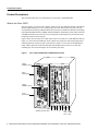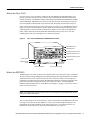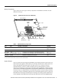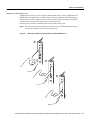
1
Doc. No. 78-2561-01
7000 Series Route Switch Processor (RSP7000)
Installation and Configuration in
the Cisco 7000 Series Routers
Product Numbers: RSP7000=, MEM-RSP-FLC8M=, MEM-RSP-FLC16M=,
MEM-RSP-FLC20M=, MEM-RSP-8M=, MEM-RSP-16M, MEM-RSP-24M,
MEM-RSP-32M(=), MEM-RSP-64M(=), and MEM-RSP-128M(=)
This document discusses the 7000 Series Route Switch Processor (RSP7000), which is a new main
processor module for the Cisco 7000 series routers: the Cisco 7000 and the Cisco 7010. The
RSP7000 combines all of the switched routing and high-speed switching functions required by the
Cisco 7000 series routers. (Refer to the section “What Is the RSP7000?” on page 3.)
The RSP7000 requires that your Cisco 7000 series router is running Cisco Internetwork Operating
System (Cisco IOS) Release 10.3(9), or later, Release 11.0(6), or later, or Release 11.1(1) or later.
Caution Using the RSP7000 in your Cisco 7000 series router might require that some currently
installed interface processors be upgraded to specific, compatible hardware versions; otherwise,
error messages and erratic system behavior might result. You can use the show diag command to
see which interface processors in your system need this hardware upgrade. For a complete list of the
potentially affected interface processors, their required hardware versions, and information on
upgrading your affected interface processors, refer to the document Verifying Interface Processor
Compatibility with the Cisco 7500 Series Investment Protection Program (IPP), Document
Number 78-2077-xx, where xx refers to the latest version of this document.
Document Contents
Following are the sections in this document:
•
•
•
•
•
•
Copyright © 1996
Cisco Systems, Inc.
All rights reserved.
Product Descriptions, page 2
Installation Prerequisites, page 7
Installation Procedures, page 18
Troubleshooting the Installation, page 23
Reference Information, page 28
Cisco Information Online, page 47
1
Product Descriptions
Product Descriptions
This section describes the Cisco 7000 and Cisco 7010 routers, and the RSP7000.
What Is the Cisco 7000?
The Cisco 7000 is a seven-slot router chassis, which uses the new RSP7000 (and the 7000 Chassis
Interface [RSP7000CI]). The Cisco 7000 provides up to five interface processor slots, and can
accommodate the following CxBus-based interface processors: Fast Ethernet, Ethernet, Token Ring,
Fiber Distributed Data Interface (FDDI), channel attachment, multichannel, serial, and so forth. The
7000 RSP and interface processors are keyed with guides on the backplane to prevent them from
being fully inserted in the wrong slot.
Figure 1 shows the rear of the Cisco 7000 router. In the Cisco 7000, slot 5 (7000 RSP slot shown in
Figure 1) is reserved for the RSP7000, which contains the system processor and performs packet
switching functions, and slot 6 (7000 CI slot shown in Figure 1) is reserved for the RSP7000CI
board, which contains all of the environmental monitoring functions for the Cisco 7000. The
remaining five slots (slots 0 through 4) are for interface processors.
Figure 1
Cisco 7000 with RSP7000 and RSP7000CI Installed
Captive
installation screw
DC
AC
FA
IL
PO
WE
EN
R
AB
LE
NO
RM
AL
Upper
power supply
EJ
EC
T
I
SL SLO
OT T
0 1
O
Captive
installation screw
CP
U
EN
AB
HA
LT
LE
RE
SE
T
DC
AC
FA
IL
PO
WE
R
Lower
power supply
AU
NS
OL
E
I
ROUTE SWITCH PROCESSOR
CO
H5288
X.
O
Interface processor slots
0
1
2
3
4
RSP RSP
7000 7000CI
slot 5 slot 6
2 7000 Series Route Switch Processor (RSP7000) Installation and Configuration in the Cisco 7000 Series Routers
Product Descriptions
What Is the Cisco 7010?
The Cisco 7010 is a five-slot chassis, which uses the new RSP7000 (and the RSP7000CI), and
provides up to three interface processor slots that can accommodate the following CxBus-based
interface processors: Fast Ethernet, Ethernet, Token Ring, Fiber Distributed Data Interface (FDDI),
channel attachment, multichannel, serial, and so forth. The processor and interface processors are
keyed with guides on the backplane to prevent them from being fully inserted in the wrong slot.
Figure 2 shows the rear of the Cisco 7010 router. In the Cisco 7010, slot 3 (7000 RSP slot shown in
Figure 2) is reserved for the RSP7000, which contains the system processor and performs packet
switching functions, and slot 4 (7000 CI slot shown in Figure 2) is reserved for the RSP7000CI
board, which contains all of the environmental monitoring functions for the Cisco 7010. The
remaining three slots (slots 0 through 2) are for interface processors.
Figure 2
Cisco 7010 with RSP7000 and RSP7000CI Installed
RSP7000CI slot 4
RSP7000 slot 3
NS
CO
AU
X.
OL
E
T
HA
SE
U
RE
CP
EC
Interface processor slot 2
AB
EN
EN
AB
LE
LE
EJ
AL
RM
NO
SL SLO
OT T
0 1
T
LT
ROUTE SWITCH PROCESSOR
Interface processor slot 1
Interface processor slot 0
Power switch
H5874
DC OK LED
Chassis ground
screw
Power receptacle
AC-input power supply
What Is the RSP7000?
The RSP7000 is a new main system processor module for the Cisco 7000 series routers. It combines
all of the switched routing and high-speed switching functions of the separate Route Processor (RP)
and Switch Processor (SP), which are used in the Cisco 7000 series routers, but with improved
performance on a single processor module. The RSP7000 contains the central processing unit (CPU)
and most of the memory components for the Cisco 7000 series routers. You must install the
RSP7000 in the appropriate chassis’ 7000 RSP slot. (See Figure 1, on page 2, for the Cisco 7000, or
Figure 2 for the Cisco 7010.)
Note For the RSP7000 to operate properly, the Cisco 7000 and Cisco 7010 chassis must also be
configured with the RSP7000CI.
The Cisco IOS images reside in Flash memory, which is located either on the RSP7000, in the form
of a single in-line memory module (SIMM), or on up to two Personal Computer Memory Card
International Association (PCMCIA) cards (called Flash memory cards) that insert in the two
PCMCIA slots (slot 0 and slot 1) on the front of the RSP7000. (See Figure 9.)
7000 Series Route Switch Processor (RSP7000) Installation and Configuration in the Cisco 7000 Series Routers
3
Product Descriptions
Storing the Cisco IOS images in Flash memory enables you to download and boot from upgraded
Cisco IOS images remotely or from software images resident in the RSP7000 Flash memory,
without having to remove and replace read-only memory (ROM) devices.
Note The RSP7000 uses a software-controlled configuration register. There are no
user-configurable jumpers on the RSP7000.
The RSP7000 contains the following components:
•
Mips R4600 Reduced Instruction Set Computing (RISC) processor, used for the CPU (The CPU
runs at an external clock speed of 50 MHz and an internal clock speed of 100 MHz.)
•
•
•
A bank of hardware (Media Access Control [MAC]–layer) addresses for the interface ports
Most of the memory components used by the system, including onboard Flash
Air-temperature sensors for environmental monitoring (All of the logic for the environmental
monitoring functions is contained on the chassis interface card.)
In addition to the system software, the RSP7000 contains and executes the following management
functions that control the system:
•
•
•
•
Sending and receiving routing protocol updates
Managing tables and caches
Monitoring interface and environmental status
Providing Simple Network Management Protocol (SNMP) management and the console/Telnet
interface
The high-speed switching section of the RSP7000 communicates with and controls the interface
processors on the high-speed CxBus. This switching section decides the destination of a packet and
switches it accordingly. The RSP7000 uses a 16-million-instructions-per-second (mips) processor to
provide high-speed, autonomous switching and routing.
4 7000 Series Route Switch Processor (RSP7000) Installation and Configuration in the Cisco 7000 Series Routers
Product Descriptions
Memory Components
Figure 3 shows the various types of memory components on the RSP7000, and Table 1 lists the
functions of each type.
Figure 3
7000 Route Switch Processor (RSP7000)
Bus connector
DRAM
SIMMs
CPU
U24
U4
Bank 0
U12
ROM monitor
(boot ROM)
NVRAM
U17
U18
Bank 1
U1
H5364
U25
Flash card
(PCMCIA) slot
Table 1
Flash SIMM
holder
Auxiliary port
Console port
RSP7000 Memory Components
Type
Size
Quantity
Description
Location
DRAM
16 to 128 MB
2 to 4
8, 16, or 32-MB SIMMs (based on maximum DRAM required)
Bank 0: U4 and U12
Bank 1: U18 and U25
NVRAM
128 KB
1
Nonvolatile EPROM for the system configuration file1
U17
Flash SIMM
Flash Card
8 MB
8, 16, and 20 MB 2
1
Up to 2
Contains the Cisco IOS images on the RSP7000 (standard)
Contains the Cisco IOS images on up to two PCMCIA cards
U1
Slot 0, slot 1
Boot ROM
256 KB
1
EPROM for the ROM monitor program
U24
1. A system configuration file is contained in NVRAM, which allows the software to control several system variables.
2. Only Intel Series 2 Flash memory cards can be used with the RSP7000.
System Software
The Cisco 7000 series routers support downloadable system software and microcode for most Cisco
IOS and microcode upgrades, which enables you to remotely download, store, and boot from a new
image. The publication Upgrading Software and Microcode in Cisco 7XXX Series Routers
(Document Number 78-1144-xx), which accompanies all Cisco IOS upgrade kits, provides
instructions for upgrading over the network or from floppy disks. Flash memory contains the default
system software. An erasable programmable read-only memory (EPROM) device contains the latest
microcode version, in compressed form, for each interface processor. At system startup, an internal
system utility scans for compatibility problems between the installed interface processor types and
the bundled microcode images, then decompresses the images into running dynamic random-access
memory (DRAM). The bundled microcode images then function the same as the EPROM images.
7000 Series Route Switch Processor (RSP7000) Installation and Configuration in the Cisco 7000 Series Routers
5
Product Descriptions
DRAM
DRAM stores routing tables, protocols, and network accounting applications. The standard
RSP7000 configuration is 16 megabytes (MB) of DRAM, with up to 128 MB available through
single in-line memory module (SIMM) upgrades.
Note When upgrading DRAM, you must use SIMMs from an approved vendor. To ensure that you
obtain the most current vendor information, obtain the list from Cisco Information Online (CIO) or
the Technical Assistance Center (TAC). (See the section “Software Prerequisites” on page 11.)
NVRAM
The system configuration, software configuration register settings, and environmental monitoring
logs are contained in the 128-kilobyte (KB), nonvolatile random-access memory (NVRAM), which
is backed up with built-in lithium batteries that retain the contents for a minimum of five years. When
replacing an RSP7000, be sure to back up your configuration to a remote server so you can retrieve
it later.
Caution Before you replace an RSP7000, back up the running configuration to a Trivial File
Transfer Protocol (TFTP) file server so you can retrieve it later. If the configuration is not saved, the
entire configuration will be lost—inside the NVRAM on the removed RSP7000—and you will have
to reenter the entire configuration manually. For instructions on how to save the configuration file,
refer to the section “Saving and Retrieving the Configuration File” on page 12. This procedure is not
necessary if you are temporarily removing an RSP7000 you will reinstall; lithium batteries retain the
configuration in memory until you replace the RSP7000 in the system.
Flash Memory
The imbedded or PCMCIA card-based Flash memory allows you to remotely load and store multiple
Cisco IOS and microcode images. You can download a new image over the network or from a local
server and then add the new image to Flash or replace the existing files. You can then boot routers
either manually or automatically from any of the stored images. Flash memory also functions as a
TFTP server to allow other servers to boot remotely from stored images or to copy the stored image
into their own Flash memory.
Note If you have a Flash memory card installed in the PCMCIA slot of your RP, and you are
replacing an RP with an RSP7000, you must reformat the Flash memory card if you want to use it
with your new RSP7000. You must install the RSP7000 in the 7000 RSP slot, have an RSP7000
Chassis Interface (RSP7000CI) installed in the 7000 CI slot, and be running Cisco IOS Release
10.3(9), or later, Release 11.0(6), or later, or Release 11.1(1) or later, for the new RSP7000 to work
properly. Using the RSP7000, you cannot read data on the RP’s Flash memory card, nor can you use
it as bootable media. You must reformat the RP’s Flash card before you can use it with the RSP7000.
Flash memory cards formatted on the RP-based systems (7000 series routers) are formatted
differently from Flash memory cards formatted on RSP-based systems (7500 series routers).
Caution The formatting procedure erases all information on the Flash memory card. To prevent the
loss of important data that might be stored on a Flash memory card, proceed carefully. If you want
to save the data on a Flash memory card, copy the data to a server before you format the card.
6 7000 Series Route Switch Processor (RSP7000) Installation and Configuration in the Cisco 7000 Series Routers
Installation Prerequisites
Jumpers
There are no user-configurable jumpers on the RSP7000.
LEDs
The two LEDs on the RSP7000 indicate the system and RSP7000 status. The normal LED is on
when the system is operational. During normal operation, the CPU halt LED should be off. The CPU
halt LED goes on only if the system detects a processor hardware failure.
Serial Ports
Two asynchronous serial ports on the RSP7000, the console and auxiliary ports, allow you to
connect external devices to monitor and manage the system. The console port is an Electronic
Industries Association/Telecommunications Industry Association (EIA/TIA)-232 receptacle
(female) that provides a data circuit-terminating equipment (DCE) interface for connecting a
console terminal.
Note EIA/TIA-232 was known as recommended standard RS-232 before its acceptance as a
standard by the Electronic Industries Association (EIA) and Telecommunications Industry
Association (TIA).
The auxiliary port is an EIA/TIA-232 plug (male) that provides a data terminal equipment (DTE)
interface; the auxiliary port supports flow control and is often used to connect a modem, a channel
service unit (CSU), or other optional equipment for Telnet management.
Installation Prerequisites
Before beginning any of these procedures, review the following sections to ensure that your
equipment configuration meets the minimum requirements for the upgrade or replacement you will
perform, and that you have all the parts and tools you will need. Also, review safety and
ESD-prevention guidelines to help you to avoid injury or damage to the equipment.
If you are replacing the existing RSP7000, upload your current configuration file to a remote server
before you remove the RSP7000 to avoid having to reenter all your current configuration
information manually. To upload the file, you need access to a remote server. Refer to the section
“Saving and Retrieving the Configuration File” on page 12, for instructions for uploading the file
and retrieving it after the new RSP7000 is installed.
Safety
This section lists safety guidelines you should follow when working with any equipment that
connects to electrical power or telephone wiring.
7000 Series Route Switch Processor (RSP7000) Installation and Configuration in the Cisco 7000 Series Routers
7
Installation Prerequisites
Electrical Equipment
Follow these basic guidelines when working with any electrical equipment:
•
Before beginning any procedures requiring access to the chassis interior, locate the emergency
power-off switch for the room in which you are working.
•
•
•
•
Disconnect all power and external cables before moving a chassis.
•
Carefully examine your work area for possible hazards such as moist floors, ungrounded power
extension cables, and missing safety grounds; correct all hazardous conditions.
Do not work alone when potentially hazardous conditions exist.
Never assume that power has been disconnected from a circuit; always check.
Do not perform any action that creates a potential hazard to people or makes the equipment
unsafe.
Telephone Wiring
Use the following guidelines when working with any equipment that is connected to telephone
wiring or to other network cabling:
•
•
Never install telephone wiring during a lightning storm.
•
Never touch uninsulated telephone wires or terminals unless the telephone line has been
disconnected at the network interface.
•
Use caution when installing or modifying telephone lines.
Never install telephone jacks in wet locations unless the jack is specifically designed for wet
locations.
Preventing Electrostatic Discharge Damage
ESD damage, which can occur when electronic cards or components are improperly handled, results
in complete or intermittent failures. Each processor module contains a printed circuit card that is
fixed in a metal carrier. Electromagnetic interference (EMI) shielding, connectors, and a handle are
integral components of the carrier. Although the metal carrier helps to protect the board from ESD,
use an ESD-preventive wrist or ankle strap whenever you handle any electronic system component.
Following are guidelines for preventing ESD damage:
•
•
Always use an ESD-preventive wrist or ankle strap and ensure that it makes good skin contact.
•
When you install a processor module, use the ejector levers to properly seat the bus connectors
in the backplane, then tighten both captive installation screws. These screws prevent accidental
removal, provide proper grounding for the system, and help to ensure that the bus connectors are
seated in the backplane.
•
Handle processor modules by the carrier handles and carrier edges only; never touch the board
or any connector pins.
When you work at the interface processor end of the chassis, connect the equipment end of the
strap to the captive installation screw on an installed interface processor, or to any unfinished
chassis surface.
8 7000 Series Route Switch Processor (RSP7000) Installation and Configuration in the Cisco 7000 Series Routers
Installation Prerequisites
•
When you remove a processor module, place it card side up on an antistatic surface or in a static
shielding bag. Immediately place the module in a static shielding bag if you need to return it to
the factory.
•
Avoid contact between electronic equipment and clothing. Antistatic straps only protect the
equipment from ESD voltages on the body; ESD voltages on clothing can still cause damage.
For safety, periodically check the resistance value of the antistatic strap. The
measurement should be between 1 and 10 megohms.
Caution
Compatibility Requirements
There are no restrictions on installing an RSP7000 in a Cisco 7000 series router, provided that you
ensure the following:
•
You install the RSP7000 in the 7000 RSP slot—slot 5 in the Cisco 7000, see Figure 1, or slot 3
in the Cisco 7010, see Figure 2
•
You have an RSP7000CI already installed in the 7000 CI slot—slot 6 in the Cisco 7000, see
Figure 1, or slot 4 in the Cisco 7010, see Figure 2
(Refer to the section “What Is the Cisco 7000?” on page 2, or the section “What Is the Cisco 7010?”
on page 3.)
For SIMM upgrades, you must obtain the replacement SIMMs from an approved vendor. To ensure
that you obtain the latest available product and vendor information, obtain the list from one of the
following sources:
•
Cisco Information Online (CIO). If you have a CIO account, you can access the list remotely.
(See the section “Cisco Information Online” at the end of this document.)
•
Technical Assistance Center at 800 553-2447, 408 526-7209, or send an e-mail message to
[email protected].
•
Customer Response Center at 800 553-6387, 408 526-7208, or send an e-mail message to
[email protected].
Although the PCMCIA card and SIMM specifications are defined in the manufacturers’ part
numbers, they must meet the following requirements:
•
•
•
Flash PCMCIA card and DRAM SIMMs must be obtained from an approved vendor
Minimum DRAM speed is 60 nanosecond (ns)
Maximum SIMM height is 1 inch
Online Insertion and Removal—An Overview
OIR allows you to remove and replace CxBus interface processors while the system is operating;
you do not need to notify the software or shut down the system power. This section describes the
mechanical functions of the system components and stresses the importance of following the correct
procedures to avoid unnecessary restarts or card failures. This section is for background information
only. Subsequent sections provide specific procedures for removing and installing an RSP7000.
7000 Series Route Switch Processor (RSP7000) Installation and Configuration in the Cisco 7000 Series Routers
9
Installation Prerequisites
Caution All CxBus interface processors support OIR; however, you must shut down the system
before removing or installing the RSP7000, which is a required system component. Removing an
RSP7000 while the system is operating will cause the system to shut down or crash, and might
damage or destroy memory files.
Each RSP7000 and interface processor contains a bus connector with which it connects to the system
backplane. The bus connector is a set of tiered pins, in three lengths. The pins send specific signals
to the system as they make contact with the backplane.
The system assesses the signals it receives and the order in which it receives them to determine what
event is occurring and what task it needs to perform, such as reinitializing new interfaces or shutting
down removed ones. For example, when you insert an interface processor, the longest pins make
contact with the backplane first, and the shortest pins make contact last. The system recognizes the
signals and the sequence in which it receives them. The system expects to receive signals from the
individual pins in this logical sequence, and the ejector levers help to ensure that the pins mate in
this sequence.
When you remove or insert an interface processor, the backplane pins send signals to notify the
system, which then performs as follows:
1 Rapidly scans the backplane for configuration changes and does not reset any interfaces.
2 Initializes all newly inserted interface processors, noting any removed interfaces and placing
them in the administratively shutdown state.
3 Brings all previously configured interfaces on the interface processor back to the state they were
in when they were removed. Any newly inserted interfaces are put in the administratively
shutdown state, as if they were present (but unconfigured) at boot time. If a similar interface
processor type has been reinserted into a slot, then its ports are configured and brought online up
to the port count of the original interface processor.
OIR functionality enables you to add, remove, or replace interface processors with the system
online, which provides a method that is seamless to end users on the network, maintains all routing
information, and ensures session preservation.
When you insert a new interface processor, the system runs a diagnostic test on the new interfaces
and compares them to the existing configuration. If this initial diagnostic test fails, the system
remains off line for another 15 seconds while it performs a second set of diagnostic tests to
determine whether or not the interface processor is faulty and if normal system operation is possible.
If the second diagnostic test passes, which indicates that the system is operating normally and the
new interface processor is faulty, the system resumes normal operation but leaves the new interfaces
disabled. If the second diagnostic test fails, the system crashes, which usually indicates that the new
interface processor has created a problem on the bus and should be removed.
The system brings online only interfaces that match the current configuration and were previously
configured as up; all other interfaces require that you configure them with the configure command.
On interface processors with multiple interfaces, only the interfaces that have already been
configured are brought online.
For example, if you replace a dual-interface Ethernet Interface Processor (EIP) with an EIP with four
interfaces, only the previously configured interfaces are brought online automatically; the new
interfaces remain in the administratively shutdown state until you configure them and bring them
online.
10 7000 Series Route Switch Processor (RSP7000) Installation and Configuration in the Cisco 7000 Series Routers
Installation Prerequisites
Software Prerequisites
The RSP7000 is compatible with Cisco IOS Release 10.3(9), or later, Release 11.0(6), or later, or
Release 11.1(1) or later. Cisco IOS Release 11.1(1) might require more than 16 MB of DRAM for
your RSP7000; refer to the section “Replacing and Upgrading DRAM SIMMs” on page 29.
The show version and show hardware commands display the current hardware configuration of the
router, including the system software version that is currently loaded and running. The
show microcode command lists the bundled microcode (target hardware) version for each processor
type. The show controller cbus command shows the microcode version you are running.
You can determine the current version of software or microcode stored in ROM either by removing
the processor module and checking the ROM labels or by configuring the system to boot the system
software or microcode from ROM, reloading the system, and using show commands to check the
version that is loaded and running. Refer to the appropriate software documentation for complete
configuration instructions and examples.
If the displays indicate that the required system software and microcode is not available in your
system, contact a customer service representative for upgrade information. (Refer to the section
“Cisco Information Online” at the end of this document.)
Hardware Prerequisites
You must install the RSP7000 in the appropriate chassis’ 7000 RSP slot. (See Figure 1, on page 2,
for the Cisco 7000, or Figure 2, on page 3, for the Cisco 7010.) For the RSP7000 to operate properly,
the Cisco 7000 and Cisco 7010 chassis must also be configured with the RSP7000CI.
Microcode Prerequisites
Microcode is a set of processor-specific software instructions that enables and manages the features
and functions of a specific processor type.
At system startup or reload, the system loads the microcode for each processor type present in the
system. The latest available microcode image for each processor type is bundled and distributed with
the system software image.
New microcode is released to enable new features, improve performance, or fix bugs in earlier
versions. The Cisco routers feature downloadable software and microcode for most upgrades. These
features enable you to download new (upgraded) images remotely, store the images in router
memory, and load the new images at system startup without having to physically access the router.
You can store multiple versions for a specific processor type in Flash memory, and use configuration
commands to specify which version the system should load at startup. All interfaces of the same type
(for example, all CIPs) use the same microcode image. Although most upgrades can be downloaded,
some exceptions require ROM replacement to ensure proper startup and operation.
Microcode images that are bundled with the system image load automatically along with the new
software image.
Note The software and interface processor microcode images are carefully optimized and bundled
to work together. Overriding the bundle can result in incompatibility between the various interface
processors in the system. We recommend that you use only the microcode image that is bundled
7000 Series Route Switch Processor (RSP7000) Installation and Configuration in the Cisco 7000 Series Routers
11
Installation Prerequisites
Flash Memory Card Replacement and Formatting Prerequisites
If you have a Flash memory card installed in the PCMCIA slot of your RP, you must reformat it if
you want to use it with your new RSP7000. Using the RSP7000, you cannot read data on the RP’s
Flash memory card, nor can you use it as bootable media. You must reformat the RP’s Flash card on
the RSP7000 before you can use it with the RSP7000. Flash memory cards formatted on the
RP-based systems (7000 series routers) are formatted differently from Flash memory cards
formatted on RSP-based systems (7500 series routers or 7000 series routers equipped with an
RSP7000).
Caution The formatting procedure erases all information on the Flash memory card. To prevent the
loss of important data that might be stored on a Flash memory card, proceed carefully. If you want
to save the data on a Flash memory card, copy the data to a server before you format the card.
Saving and Retrieving the Configuration File
This section describes the procedures for saving and retrieving the system configuration.
Configuration information resides in two places when the router is operating: the default
(permanent) configuration in NVRAM, and the running (temporary) memory in RAM. The default
configuration always remains available; NVRAM retains the information even when the power is
shut down. The current information is lost when if the system power is shut down. The current
configuration contains all nondefault configuration information that you added with the configure
command, the setup command facility, or by editing the configuration file.
The copy running-config startup-config command adds the current configuration to the default
configuration in NVRAM, so that it will also be saved when power is shut down. Whenever you
make changes to the system configuration, issue the copy running-config startup-config command
to ensure that the new configuration is saved.
If you replace the RSP7000, you will also replace the entire configuration (NVRAM resides in
socket U17 on the RSP7000). If you upload (copy) the configuration file to a remote server before
removing the RSP7000, you can retrieve it later and write it into NVRAM on the new RSP7000. If
you do not upload the configuration file, you will have to use the configure command or the setup
command facility to reenter the configuration information after you install the new RSP7000. For
complete descriptions of these commands and instructions for using them, refer to the appropriate
software documentation.
This procedure is not necessary if you are temporarily removing an RSP7000 that you will reinstall;
the lithium batteries will retain the configuration in memory until you replace the RSP7000 in the
system.
This procedure requires privileged-level access to the EXEC command interpreter, which usually
requires a password. Refer to the description that follows and contact your system administrator if
necessary, to obtain access.
12 7000 Series Route Switch Processor (RSP7000) Installation and Configuration in the Cisco 7000 Series Routers
Installation Prerequisites
Using the EXEC Command Interpreter
Before you use the configure command, you must enter the privileged level of the EXEC command
interpreter with the enable command. The system prompts you for a password if one has been set.
The system prompt for the privileged level ends with a pound sign (#) instead of an angle bracket
(>). At the console terminal, enter the privileged level as follows:
Step 1 At the user-level EXEC prompt (>), enter the enable command. The EXEC command
interpreter prompts you for a privileged-level password, as follows:
Router> enable
Password:
Step 2 Enter the password (the password is case sensitive). For security purposes, the password is
not displayed.
Step 3 When you enter the correct password, the system displays the privileged-level system
prompt (#), as follows:
Router#
The pound sign (#) at the system prompt indicates that you are at the privileged level of the EXEC
command interpreter; you can now execute the EXEC-level commands that are described in the
following sections.
Using the Ping Command
Before you attempt to upload or retrieve a file from a remote host, ensure that the connection is good
between the router and the remote server. The packet internet groper (ping) program sends a series
of echo request packets to the remote device and waits for a reply. If the connection is good, the
remote device echoes them back to the local device.
The console terminal displays the results of each message sent: an exclamation point (!) indicates
that the local device received an echo, and a period (.) indicates that the server timed out while
awaiting the reply. If the connection between the two devices is good, the system will display a series
of exclamation points (! ! !) or [ok]. If the connection fails, the system will display a series of periods
( . . . ) or [timed out] or [failed].
To verify the connection between the router and a remote host, issue the ping command followed by
the name or Internet Protocol (IP) address of the remote server, then press Return. Although the
ping command supports configurable options, the defaults, including interface processor as the
protocol, are enabled when you enter a host name or address on the same line as the ping command.
For a description of the configurable options, refer to the appropriate software documentation.
The following example shows a successful ping:
Router# ping 1.1.1.1
Type escape sequence to abort.
Sending 5, 100-byte ICMP Echos to 1.1.1.1, timeout is 2 seconds:
!!!!!
Success rate is 100 percent (5/5), round-trip min/avg/max = 12/12/12 ms
Router#
7000 Series Route Switch Processor (RSP7000) Installation and Configuration in the Cisco 7000 Series Routers
13
Installation Prerequisites
The following example shows the results of a failed ping:
Sending 5, 100-byte ICMP Echos to 1.1.1.1, timeout is 2 seconds:
.....
Success rate is 0 percent (0/5)
Router#
If the connection fails, check the physical connection to the remote file server and verify that you are
using the correct address or name, then ping the server again. If you are unable to establish a good
connection, contact your network administrator or refer to the end of this document for instructions
on contacting technical assistance.
Uploading (Copying) the Configuration File
Before you upload (copy) the running configuration to the TFTP file server, ensure the following:
•
You have a connection to the router either with a console terminal connected to the RSP7000
console port, or remotely through a Telnet session.
•
•
•
The router is connected to a network supporting a file server (remote host).
The remote host supports the TFTP application.
You have the interface processor address or name of the remote host available.
To store information on a remote host, enter the write network (or copy startup-config tftp)
privileged EXEC command. The command prompts you for the destination host’s address and a
filename, and then displays the instructions for confirmation. When you confirm the instructions, the
router sends a copy of the currently running configuration to the remote host. The system default is
to store the configuration in a file called by the name of the router with -confg appended. You can
either accept the default filename by pressing Return at the prompt, or enter a different name before
pressing Return.
Follow these steps to upload (copy) the currently running configuration to a remote host:
Step 1 The system prompt should display a pound sign (#) to indicate the privileged level of the
EXEC command interpreter. If it does not, follow the steps in the section “Using the EXEC
Command Interpreter” on page 13 to enable the privileged level.
Step 2 Use the ping command to check the connection between the router and the remote host.
(See the previous section, “Using the Ping Command.”)
Step 3 Issue the write term (or show running-config) command to display the currently running
configuration on the terminal, and ensure that the configuration information is complete
and correct. If it is not, use the configure command to add or modify the existing
configuration. (Refer to the appropriate software documentation for descriptions of the
configuration options available for the system and individual interfaces, and for specific
configuration instructions.)
14 7000 Series Route Switch Processor (RSP7000) Installation and Configuration in the Cisco 7000 Series Routers
Installation Prerequisites
Step 4 Issue the write net (or copy startup-config tftp) command. The EXEC command
interpreter prompts you for the name or interface processor address of the remote host that
is to receive the configuration file. (The prompt might include the name or address of a
default file server.)
Router# write net
Remote host []?
Step 5 Enter the name or interface processor address of the remote host. In the following example,
the name of the remote server is servername:
Router# write net
Remote host []? servername
Translating "servername"...domain server (1.1.1.1) [OK]
Step 6 The EXEC command interpreter prompts you for the name of the file that will contain the
configuration. By default, the system appends -confg to the router’s name to create the new
filename. Press Return to accept the default filename, or enter a different name for the file
before pressing Return. In the following example, the default is accepted:
Name of configuration file to write [Router-confg]?
Write file Router-confg on host 1.1.1.1? [confirm]
Writing Router-confg .....
Step 7 Before the router executes the copy process, it displays the instructions you entered for
confirmation. If the instructions are not correct, enter n (no) then Return to abort the
process. To accept the instructions, press Return or y then Return, and the system will
begin the copy process. In the following example, the default is accepted:
Write file Router-confg on host 1.1.1.1? [confirm]
Writing Router-confg: !!!! [ok]
While the router copies the configuration to the remote host, it displays a series of
exclamation points (! ! !) or periods (. . .). The !!!! and [ok] indicate that the operation is
successful. A display of . . . [timed out] or [failed] indicates a failure, which would probably
be due to a network fault or the lack of a writable, readable file on the remote file server.
Step 8 If the display indicates that the process was successful (with the series of ! ! ! and [ok]), the
upload process is complete. The configuration is safely stored in the temporary file on the
remote file server.
If the display indicates that the process failed (with the series of . . . as shown in the
following example):
Writing Router-confg .....
your configuration was not saved. Repeat the preceding steps, or select a different remote
file server and repeat the preceding steps.
After you upload the configuration file, proceed to “Removing the RSP7000” on page 18. If you are
unable to copy the configuration to a remote host successfully, contact your network administrator
or refer to the end of this document for instructions on contacting technical assistance.
7000 Series Route Switch Processor (RSP7000) Installation and Configuration in the Cisco 7000 Series Routers
15
Installation Prerequisites
Downloading (Retrieving) the Configuration File
After you install the new RSP7000, you can retrieve the saved configuration and copy it to NVRAM.
To retrieve the configuration, enter configuration mode and specify that you will configure the router
from the network. The system prompts you for a host name and address, the name of the
configuration file stored on the host, and confirmation to reboot using the remote file.
You can access the router through a console terminal attached directly to the RSP7000 console port,
or you can configure an interface port and Telnet to the router from a remote terminal.
Follow these steps to download (retrieve) the currently running configuration from a remote host:
Step 1 On the console terminal, the system prompt should display a pound sign (#) to indicate the
privileged level of the EXEC command interpreter. If it does not, follow the steps in the
section “Using the EXEC Command Interpreter” on page 13 to enable the privileged level.
Note Until you retrieve the previous configuration, the router will be running from the default
configuration in NVRAM. Therefore, any passwords that were configured on the previous system
will not be valid until you retrieve the configuration.
Step 2 Use the ping command to verify the connection between the router and the remote host.
(See the section “Using the Ping Command” on page 13.)
Step 3 At the system prompt, issue the configure network (or copy tftp startup-config)
command and press Return to enter the configuration mode and specify that you will
configure the system from a network device (instead of from the console terminal, which
is the default).
Router# configure network
Step 4 The system will ask you to select a host or network configuration file. The default is host;
press Return to accept the default.
Host or network configuration file [host]?
Step 5 The system prompts you for the interface processor address of the host. Enter the interface
processor address or name of the remote host (the remote file server to which you uploaded
the configuration file).
IP address of remote host [255.255.255.255]? 1.1.1.1
Step 6 The system prompts you for the name of the configuration file. When uploading the file, the
default is to use the name of the router with the suffix -confg (router-confg in the following
example). If you specified a different filename when you uploaded the configuration, enter
the filename; otherwise, press Return to accept the default.
Name of configuration file [router-confg]?
16 7000 Series Route Switch Processor (RSP7000) Installation and Configuration in the Cisco 7000 Series Routers
Installation Prerequisites
Step 7 Before the system reboots with the new configuration, it displays the instructions you
entered for confirmation. If the instructions are not correct, enter n (no) then press Return
to cancel the process. To accept the instructions, press Return, or y then Return.
Configure using router-confg from 1.1.1.1? [confirm]
Booting router-confg from 1.1.1.1: ! ! [OK - 874/16000 bytes]
While the router retrieves and boots from the configuration on the remote host, the console
display indicates whether or not the operation was successful. A series of !!!! and [OK] (as
shown in the preceding example) indicates that the operation was successful. A series of . . .
and [timed out] or [failed] indicate a failure (which would probably be due to a network
fault or an incorrect server name, address, or filename). The following is an example of a
failed attempt to boot from a remote server:
Booting Router-confg ..... [timed out]
Step 8 If the display indicates that the process was successful, proceed to the next step.
If the display indicates that the process failed, verify the name or address of the remote
server and the filename, and repeat the preceding steps. If you are unable to retrieve the
configuration, contact your network administrator or refer to the end of this document for
instructions on obtaining technical assistance.
Step 9 Issue the write term (or show running-config) command to display the currently running
configuration on the terminal. Review the display and ensure that the configuration
information is complete and correct. If it is not, verify the filename and repeat the preceding
steps to retrieve the correct file, or use the configure command to add or modify the existing
configuration. (Refer to the appropriate software documentation for descriptions of the
configuration options available for the system and individual interfaces and specific
configuration instructions.).
Step 10 When you have verified that the currently running configuration is correct, issue the
copy running-config startup-config command to save the retrieved configuration in
NVRAM. Otherwise, the new configuration will be lost if you restart the system. This
completes the procedure for downloading (retrieving) the configuration file.
List of Tools and Parts
You need some or all of the following tools and parts to remove and replace an RSP7000. If you need
additional equipment, contact a customer service representative for ordering information.
•
Number 2 Phillips or 3/16-inch, flat-blade screwdriver for the captive installation screws that
secure the RSP7000 in its slot.
•
ESD-prevention equipment or the disposable ESD-preventive wrist strap included with all spares
and upgrade kits.
•
Antistatic mat, foam pad, or bag for the removed RSP7000 (place the removed RSP7000 into an
antistatic bag if you plan to return it to the factory, or on an antistatic mat or foam if you are
replacing components and will reinstall the RSP7000)
If you are replacing SIMMs, you will need 60-ns SIMMs from an approved vendor
7000 Series Route Switch Processor (RSP7000) Installation and Configuration in the Cisco 7000 Series Routers
17
Installation Procedures
Installation Procedures
The following sections describe the procedures for installing or replacing processor modules. Before
installing any new interfaces, ensure that your system meets the minimum software and microcode
requirements described in the sections “Software Prerequisites” and “Microcode Prerequisites” on
page 11.
Note The OIR feature allows you to remove and install interface processors without turning off
system power. However, you must shut down the system before removing or installing the RSP7000,
which is a required system component.
Caution To avoid unnecessary errors, read the following OIR overview before removing or
replacing an RSP7000. If you want to save the configuration data in onboard NVRAM, then copy
the data to a server before you format the card; otherwise, the configuration data will be lost. Refer
to the section “Saving and Retrieving the Configuration File” on page 12.
Following the OIR overview, proceed to the section “Removing the RSP7000” for instructions on
removing the RSP7000, and then to the section “Replacing the RSP7000,” on page 19, for the
installation instructions. After the new RSP7000 is secure, follow the procedures in the section
“Troubleshooting the Installation” on page 23 to verify that the new RSP7000 is installed and
functioning properly.
Removing the RSP7000
When you remove or install the RSP7000, be sure to use the ejector levers, which help to ensure that
the RSP7000 is fully inserted in the backplane or fully dislodged from it. Any RSP7000 or interface
processor that is only partially connected to the backplane can halt the system.
Figure 4 on page 20 shows a detail of the ejector lever mechanism in a vertical position that is
appropriate for the Cisco 7000; the Cisco 7010 slots are oriented horizontally.
When you simultaneously push the ejector levers inward (toward the carrier handle), the levers push
the RSP7000 into the slot and ensure that the board connectors are fully seated in the backplane.
Caution You must shut down the system before removing or installing the RSP7000, which is a
required system component. Removing an RSP7000 while the system is operating will cause the
system to shut down or crash and might damage or destroy memory files.
Follow these steps to remove the RSP7000:
Step 1 Optional step: If you are replacing the RSP7000, upload (copy) the currently running
configuration file to a TFTP server so you can retrieve it later. (See the section “Saving and
Retrieving the Configuration File” on page 12.)
Step 2 Slip on an antistatic strap and connect the equipment end of the strap to a captive
installation screw on an installed interface processor, or to any unfinished chassis surface.
18 7000 Series Route Switch Processor (RSP7000) Installation and Configuration in the Cisco 7000 Series Routers
Installation Procedures
Step 3 If you are replacing the RSP7000, disconnect any devices that are attached to the console
or auxiliary ports. If you are removing the RSP7000 for maintenance and will reinstall the
same one, you can leave the devices attached provided that doing so will not strain the
cables.
Step 4 Use a screwdriver (number 2 Phillips or 3/16-inch flat-blade) to loosen the two captive
installation screws. (See Figure 4 on page 20.)
Step 5 Place your thumbs on the ends of each of the ejectors and simultaneously pull them both
outward, away from the carrier handle (in the opposite direction from that shown in
Figure 4c) to release the carrier from the slot and to dislodge the RSP7000 from the
backplane.
Step 6 Grasp the handle with one hand and pull the RSP7000 straight out of the slot, keeping your
other hand under the carrier to guide it. (See Figure 4.) Keep the carrier parallel to the
backplane. Avoid touching the board or any connector pins.
Step 7 Place the removed RSP7000 on an antistatic mat or foam. If you plan to return the RSP7000
to the factory, immediately place it in an antistatic bag to prevent ESD damage.
This completes the removal procedure. If you removed the RSP7000 to replace SIMMs, proceed to
the appropriate section. If you are replacing the RSP7000, proceed to the next section to install the
new RSP7000.
Replacing the RSP7000
Ensure that all system power is turned off before installing the RSP7000 in the chassis. The
RSP7000 is keyed for installation only in the 7000 RSP slot. (See Figures 1 and 2.)
Follow these steps to install an RSP7000:
Step 1 Ensure that all power supplies are turned OFF.
Step 2 Grasp the RSP7000 handle with one hand and place your other hand under the carrier to
support and guide it into the slot. (See Figure 4.) Avoid touching the board or any
connectors.
7000 Series Route Switch Processor (RSP7000) Installation and Configuration in the Cisco 7000 Series Routers
19
Installation Procedures
Note Figure 4 shows a typical processor module installation, and is not intended to indicate or
recommend a particular slot location for the RSP7000. Processor module slots in the Cisco 7010 are
oriented horizontally
Figure 4
Ejector Levers and Captive Installation Screws, Cisco 7000 Orientation Shown
Bottom ejector lever
a
Processor
module
carrier guide
Processor module
slot
Captive
installation
screw
c
b
H1482a
STOP!
on contact
Step 3 Place the back of the RSP7000 in the 7000 RSP slot and align the notches along the edge
of the carrier with the grooves in the slot. (See Figure 4a.)
Caution To prevent damage to the backplane, you must install the RSP7000 in slot 5 of the
Cisco 7000 (see Figure 1) or slot 3 of the Cisco 7010 (see on Figure 2) The slots are keyed for correct
installation. Forcing the RSP7000 into a different slot can damage the backplane and the RSP7000.
20 7000 Series Route Switch Processor (RSP7000) Installation and Configuration in the Cisco 7000 Series Routers
Installation Procedures
Step 4 While keeping the RSP7000 parallel to the backplane, carefully slide the carrier into the
7000 RSP slot until the RSP7000 faceplate makes contact with the ejector levers, then stop.
(See Figure 4b.)
Step 5 Using the thumb and forefinger of each hand to pinch each ejector, simultaneously push
both ejectors inward (toward the handle) until they parallel to the faceplate. (See Figure 4c.)
Step 6 Use a screwdriver (number 2 Phillips or 3/16-inch flat-blade) to tighten the captive
installation screws on the ends of the RSP7000. (See Figure 4a.)
Tighten the two captive screws on the RSP7000 faceplate to prevent the RSP7000 from
becoming partially dislodged from the backplane and to ensure proper EMI shielding.
(These screws must be tightened to meet EMI specifications.)
Step 7 If you disconnected the console terminal to remove the RSP7000, or if you are installing a
new RSP7000, connect the console terminal to the console port.
Step 8 Ensure that the console terminal is turned on.
Step 9 Turn the system power back ON, and proceed to the next section to check the installation.
Restarting and Checking the System
When you turn the system power back on, verify that the system boots and resumes normal
operation. If you are restarting the system after upgrading the DRAM expect that it will take the
system longer to complete the memory initialization portion of the boot sequence with more DRAM.
(See the section “System Startup Sequence” on page 25.)
Follow these steps to verify that the RSP7000 is installed and functioning properly:
Step 1 Check the RSP7000 connections to make sure they are secure:
•
The RSP7000 is inserted all the way into its slot, and both of the captive installation
screws are tightened.
•
The console terminal is turned on and is connected to the console port.
Step 2 Observe the RSP7000 LEDs. While the system initializes, the yellow boot error LED on
the RSP7000 stays on, then goes off when the boot is complete. As the RSP7000 initializes
each interface processor, the status LEDs on each interface processor go on and off in
irregular sequence.
Step 3 Verify that the console terminal displays the system banner and startup screen as the system
restarts. The display should look similar to the following:
Cisco Internetwork Operating System Software
IOS (tm) GS Software (RSP-K), 10.3(9), RELEASED SOFTWARE
Copyright (c) 1986-1996 by cisco Systems, Inc.
Compiled Wed 10-May-95
System Bootstrap, Version 5.3(9)
Current date and time is Sat 5-13-1995 21:38:35
Boot date and time is Thur 5-11-1995 15:32:28
[displayed text omitted from this example]
7000 Series Route Switch Processor (RSP7000) Installation and Configuration in the Cisco 7000 Series Routers
21
Installation Procedures
Step 4 After the system boots the software and initializes the interface processors (approximately
30 seconds for systems with 16 MB of DRAM, and approximately 2 minutes for systems
with 64 MB of DRAM), verify that the RSP7000 LEDs are in the following states:
•
•
•
RSP7000 normal LED is on
CPU halt LED is off
Boot error LED is off
Step 5 Verify that all the enabled LEDs (on the interface processors) are on.
When you have verified all the conditions in Steps 2 through 5, the installation is complete.
If you replaced the RSP7000 and saved your configuration file to a remote server before doing so,
proceed to the section “Downloading (Retrieving) the Configuration File” on page 16.
If you replaced the RSP7000 and did not save the configuration, use the configure command or the
setup command facility to reenter the configuration information.
An error condition exists if no LEDs go on at power up or after initialization, or if the boot error or
CPU halt LEDs go on and remain on. If this happens, proceed to the following section,
“Troubleshooting the Installation,” to try to isolate the problem.
Formatting the Flash Memory Card
If you had a Flash memory card installed in the PCMCIA slot of your RP and want to use it with
your RSP7000, you must first reformat it before you can use it with your new RSP7000. Using the
RSP7000, you cannot read data on the RP’s Flash memory card, nor can you use it as bootable
media. You must reformat the RP’s Flash card before you can use it with the RSP7000. Flash
memory cards formatted on the RP-based systems (7000 series routers) are formatted differently
from Flash memory cards formatted on RSP-based systems (7500 series routers).
Caution The formatting procedure erases all information on the Flash memory card. To prevent the
loss of important data that might be stored on a Flash memory card, proceed carefully. If you want
to save the data on a Flash memory card, copy the data to a server before you format the card.
Note Refer to the section “Saving and Retrieving the Configuration File” on page 12.
22 7000 Series Route Switch Processor (RSP7000) Installation and Configuration in the Cisco 7000 Series Routers
Troubleshooting the Installation
Use the following procedure to format a new Flash memory card:
Step 1 Insert the Flash memory card into slot 0. (If slot 0 is not available, use slot 1.)
Step 2 To format the Flash memory card, use the format slot0: (or format slot1:) command as
follows. (Use only Intel Series 2+ Flash memory cards.)
Router# format slot0:
All sectors will be erased, proceed? [confirm]
Enter volume id (up to 30 characters): MyNewCard
Formatting sector 1
Format device slot0 completed
Router#
Note For this example, an 8-MB Flash memory card was used, and at the line “Formatting sector,”
the system counted the card’s sectors backwards from 64 to 1 as it formatted them. For 16-MB Flash
memory cards, the system counts backwards from 128 to 1, and for 20-MB Flash memory cards, the
system counts backwards from 160 to 1.
The new Flash memory card is now formatted and ready to use.
Troubleshooting the Installation
This section contains procedures to follow if the system does not restart and boot as expected.
Review the descriptions that follow so you can anticipate the expected system startup sequence.
Then restart the system and try to isolate the problem by observing the LEDs as the system attempts
to boot the software and initialize the RSP7000 and each interface processor.
Verifying LEDs
Following are functional descriptions of the LEDs on the power supplies and processor modules, and
the behavior you should observe at system startup.
System Power LEDs
On the Cisco 7000 series routers, the DC LED is located on the power supply. If the DC LED goes
on and stays on, there is most likely a problem with the input power or one of the internal DC lines.
The DC LED will go on if the power supply reaches an out-of-tolerance voltage condition.The
power supply will shut down during startup if it detects an over-or undervoltage condition during
startup. For detailed descriptions of environmental monitoring functions, refer to the Cisco 7000
Hardware Installation and Maintenance or Cisco 7010 Hardware Installation and Maintenance
publications on UniverCD or in print.
RSP7000 LEDs
Figure 5 shows the LEDs on the RSP7000 faceplate. The LEDs on the RSP7000 indicate the system
and RSP7000 status and which Flash memory card slot is active. The CPU halt LED, which goes on
only if the system detects a processor hardware failure, should remain off. A successful boot is
indicated when the normal LED goes on; however, this does not necessarily mean that the system
has reached normal operation. During normal operation, the CPU halt LED should be off, and the
normal LED should be on.
7000 Series Route Switch Processor (RSP7000) Installation and Configuration in the Cisco 7000 Series Routers
23
Troubleshooting the Installation
The slot 0 and slot 1 LEDs indicate which PCMCIA (Flash memory) card slot is in use, and each
LED blinks when the card is accessed by the system.
Note The RSP7000 is oriented horizontally in the Cisco 7010 router.
Caution The reset switch (see Figure 5) resets the RSP7000 and the entire system. To prevent
system errors and problems, use it only at the direction of your service representative.
Figure 5
RSP7000 LEDs, Cisco 7000 Orientation Shown
NO
RM
AL
EJ
EC
T
S
OT LOT
0 1
SL
CP
UH
AL
T
SE
T
H5378
RE
24 7000 Series Route Switch Processor (RSP7000) Installation and Configuration in the Cisco 7000 Series Routers
Troubleshooting the Installation
Interface Processor LEDs
Each interface processor contains an enabled LED. The enabled LED goes on to indicate that the
interface processor is operational and that it is powered up. It does not necessarily mean that the
interface ports on the interface processors are functional or enabled. When the boot sequence is
complete, all of the enabled LEDs should go on.
If any do not, one of the following errors is indicated:
•
The interface processor is not installed correctly (it is not fully seated in the backplane
connector).
•
•
The microcode and software that are loading at startup are not compatible.
The interface processor has failed.
System Startup Sequence
By checking the state of the LEDs, you can determine when and where the system failed in the
startup sequence. Because you turn on the system power with the on/off switches on each power
supply, it is easiest to observe the startup behavior from the rear of the chassis. Use the following
descriptions of the normal startup sequence to isolate the problem, then use the troubleshooting
procedures wherever the system fails to operate as expected. If you are able to isolate the problem
to a faulty hardware component, or if you are unable to successfully restart the system, refer to the
end of this document for instructions on contacting a service representative.
Note The time required for the system to initialize (boot) varies with different router configurations
and the amount of memory that must be initialized. During the system startup sequence, the time
required to initialize the memory (not necessarily the entire boot sequence) in a system that contains
128 MB of DRAM will be longer than in a system that contains 16 MB of DRAM.
During the boot sequence, the system banner display pauses while it initializes the memory. If your
router has more than 16 MB of DRAM, you may notice an increase in the amount of time required
to initialize the memory. The pause in the banner display occurs after the copyright line, and before
the system displays the list of installed hardware, as shown in the following display:
%SYS-5-RELOAD: Reload requested
System Bootstrap, Version 5.3(9)
Copyright (c) 1986-1995 by cisco Systems, Inc.
[System initializes memory at this point in the display]
Note The procedures in this section are based on the assumption that your system was operating
correctly until you removed (or replaced) the RSP7000. If the following sequence indicates a new
problem with the power subsystem or one of the interface processors, refer to the Cisco 7000
Hardware Installation and Maintenance or Cisco 7010 Hardware Installation and Maintenance
publications for system startup troubleshooting procedures.
7000 Series Route Switch Processor (RSP7000) Installation and Configuration in the Cisco 7000 Series Routers
25
Troubleshooting the Installation
Use the following startup sequences and troubleshooting procedures to isolate system problems:
1 When you restart up the system, the system power the DC LED (called the DC fail LED in the
Cisco 7000 and the DC OK LED in the Cisco 7010) should not go on.
— If the system power LED remains off, the RSP7000 is probably not fully inserted and
connected to the backplane. Loosen the captive installation screws on the RSP7000, then use
the ejector levers to release the RSP7000 and reseat it in the backplane. (For a description
and illustration of the ejector levers, refer to the section “Removing the RSP7000” on
page 18.) Tighten both captive installation screws.
If the DC LED on the power supply still goes on, a power supply or input power failure could
be the problem. Before contacting a service representative, refer to the Cisco 7000 Hardware
Installation and Maintenance or Cisco 7010 Hardware Installation and Maintenance
publications for power subsystem troubleshooting procedures.
— If the system power LED goes on, the power source is good and the power supply is
functional.
When the system power LED indicates normal operation, proceed to number 2.
2 Listen for the fans. You should hear them start operating immediately after you turn on the
system power. If you determine that the power supply is functioning normally and that a fan (or
the fan array) is faulty, contact a service representative. If the fan array does not function properly
at initial startup, you cannot make any installation adjustments.
3 When you have verified that the power supply is functioning properly, observe the LEDs on the
RSP7000. The CPU halt LED on the RSP7000 should always remain off. If it goes on during the
startup sequence, the system has encountered a processor hardware error.
— Use the show config command to check the configuration register settings.
— If the CPU halt LED goes on during a second startup attempt, suspect a processor hardware
error and contact a service representative.
4 During the boot process, the LEDs on most of the interfaces light in irregular sequence; this does
not indicate either correct system startup or failure.
5 When the system boot is complete, the RSP7000 begins to initialize the interface processors.
During this initialization, the LEDs on each interface processor behave differently (most flash on
and off). The enabled LED on each interface processor goes on when initialization has been
completed.
— If the enabled LEDs on the interface processors go on, the system has booted successfully
and is now functional.
— If the RSP7000 LEDs previously indicated a successful system boot, but none of the enabled
LEDs on the interface processors go on, suspect that one of them has shifted out of its
backplane connector and halted the system. Use the ejector levers to release the interface
processor and reseat it in the backplane. (For an illustration of the ejector levers, refer to
Figure 4 on page 20.) Tighten both captive installation screws.
— If the enabled LED on a single interface processor remains off, suspect that the interface
processor has shifted out of its slot. Use the ejector levers to release the interface processor
and reseat it in the backplane. (For an illustration of the ejector levers, refer to Figure 4 on
page 20.) Tighten both captive installation screws. After the system reinitializes the
interfaces, the enabled LED on the interface processor should go on.
— If an enabled LED still fails to go on after performing these steps, suspect that the specific
interface processor has failed.
26 7000 Series Route Switch Processor (RSP7000) Installation and Configuration in the Cisco 7000 Series Routers
Troubleshooting the Installation
6 When the system boot is complete and all interface processors have been initialized, the console
screen displays a script and system banner similar to the following:
GS Software (RSP-K), Version 10.3(9)
Copyright (c) 1986-1995 by Cisco Systems, Inc.
Compiled Wed 10-May-95 11:06
— If all the previous conditions are met and this banner is displayed, the system startup was
successful and your installation is complete.
— If an error message is displayed on the terminal, refer to the appropriate software publication
for error message definitions.
— If the console screen is blank, check the terminal and ensure that it is turned on and that the
console cable is correctly connected between the terminal and the console port on the
RSP7000.
— Check the terminal settings and ensure that the terminal is set for 9600 baud, 8 data bits, no
parity, and 2 stop bits.
— If the terminal is set correctly and still fails to operate, suspect that the terminal is faulty.
Connect a different terminal and restart the system.
If the system still fails to start up or operate properly, or if you isolate the cause of the problem to a
failed component, contact a service representative for further assistance. This completes the
RSP7000 installation and replacement procedure. For complete command descriptions and
examples, refer to the appropriate software documentation.
7000 Series Route Switch Processor (RSP7000) Installation and Configuration in the Cisco 7000 Series Routers
27
Reference Information
Reference Information
Following is reference information for console and auxiliary port pinouts, replacing DRAM SIMMs,
configuring the software configuration register, recovering a lost password, and using the front-panel
PCMCIA slots for additional Flash memory.
Console Port Signals
The console port on the RSP7000 is an EIA/TIA-232, DCE, DB-25 receptacle. Both DSR and DCD
are active when the system is running. The RTS signal tracks the state of the CTS input. The console
port does not support modem control or hardware flow control. The console port requires a
straight-through EIA/TIA-232 cable. Table 2 lists the signals used on this port.
Table 2
Console Port Signals
Pin
Signal
Direction
Description
1
GND
–
2
TxD
<—
Transmit Data
3
RxD
—>
Receive Data
6
DSR
—>
Data Set Ready (always on)
7
GND
–
8
DCD
—>
Ground
Ground
Data Carrier Detect (always on)
Auxiliary Port Signals
The auxiliary port on the RSP7000 is an EIA/TIA-232 DTE, DB-25 plug to which you can attach a
CSU/DSU or other equipment in order to access the router from the network. Table 3 lists the
EIA/TIA-232 signals used on this port.
The asynchronous auxiliary port supports hardware flow control and modem control.
Table 3
Auxiliary Port Signals
Pin
Signal
Direction
Description
2
TxD
—>
Transmit Data
3
RxD
<—
Receive Data
4
RTS
—>
Request To Send (used for hardware flow control)
5
CTS
<—
Clear To Send (used for hardware flow control)
6
DSR
<—
Data Set Ready
7
Signal Ground
–
Signal Ground
8
CD
<—
Carrier Detect (used for modem control)
20
DTR
—>
Data Terminal Ready (used for modem control)
28 7000 Series Route Switch Processor (RSP7000) Installation and Configuration in the Cisco 7000 Series Routers
Reference Information
Replacing and Upgrading DRAM SIMMs
This section describes the steps for increasing the amount of DRAM by replacing up to four SIMMs
that you obtain from an approved vendor. The system DRAM resides on up to four SIMMs on the
RSP7000. The DRAM SIMM sockets are U4 and U12 for Bank 0, and U18 and U25 for Bank 1.
The default DRAM configuration is 16 MB (two 8-MB SIMMs in Bank 0). (See Figure 6.)
Note The total number of memory devices per SIMM differs for each manufacturer. The SIMMs
in the following illustrations are generic representations of the actual DRAM SIMMs for your
RSP7000. To be sure that you are using the correct SIMMs, refer to the specific part or product
numbers indicated in the approved vendor list (AVL) and by your DRAM upgrade requirements.
Figure 6
RSP7000 DRAM SIMMs
Bus connector
DRAM
SIMMs
CPU
U24
U4
Bank 0
U12
ROM monitor
(boot ROM)
NVRAM
U17
U18
Bank 1
U1
H5364
U25
Flash card
(PCMCIA) slot
Flash SIMM
holder
Auxiliary port
Console port
The SIMM sockets use the thumb tabs that are often used in PCs and other computer equipment.
Each RSP7000 SIMM socket has two metal retaining springs, one at each end. (See Figure 7 on
page 31.) When a SIMM is fully seated in the socket, the retaining springs snap over the ends of the
SIMM to lock it in the socket.
7000 Series Route Switch Processor (RSP7000) Installation and Configuration in the Cisco 7000 Series Routers
29
Reference Information
Before proceeding, ensure that you have the proper tools and ESD-prevention equipment available.
To upgrade DRAM, you install SIMMs in one or two banks. Table 4 lists the various configurations
of DRAM SIMMs that are available. Note which banks are used given the combinations of available
SIMM sizes and the maximum DRAM you require. SIMMs must be 60 ns or faster and no taller than
one inch.
Note Depending on your router configuration, Cisco IOS Release 11.1(1) might require more than
16 MB of DRAM for your RSP7000. Upgrade your system DRAM based on your current
configuration and this potential requirement.
Table 4
DRAM SIMM Configurations
DRAM Bank 0
Quantity
DRAM Bank 1
Quantity
Total DRAM
Product Names
U4 and U12
2, 8-MB SIMMs
U18 and U25
–
16 MB
MEM-RSP-16M
1
U4 and U12
2, 8-MB SIMMs
U18 and U25
2, 4-MB SIMMs
24 MB
MEM-RSP-24M
U4 and U12
2, 16-MB SIMMs
U18 and U25
–
32 MB
MEM-RSP-32M(=)
U4 and U12
2, 32-MB SIMMs
U18 and U25
–
64 MB
MEM-RSP-64M(=)
U4 and U12
2, 32-MB SIMMs
U18 and U25
2, 32-MB SIMMs
128 MB
MEM-RSP-128M(=)
1. The 24-MB DRAM configuration is also available as an 8-MB upgrade to the standard 16-MB configuration, by adding
DRAM-Product Number MEM-RSP-8M= (consisting of two, 4-MB DRAM SIMMs), for a total of 24 MB.
Caution To prevent DRAM errors, each DRAM bank used must contain no less than two SIMMs
of the same type. You must install either two SIMMs in bank 0 or four SIMMs in two banks.
Removing SIMMs
Place removed SIMMs on an antistatic mat and store them in an antistatic bag. You can use the
SIMMs that you remove in compatible equipment.
Caution To prevent ESD damage, handle SIMMs by the card edges only.
Follow these steps to remove the existing SIMMs:
Step 1 Turn OFF the system power and follow the steps in the section “Removing the RSP7000”
on page 18.
Step 2 Place the RSP7000 on an antistatic mat or pad, and ensure that you are wearing an antistatic
device, such as a wrist strap. Position the RSP7000 so that the handle is away from you,
and the edge connector is toward you; opposite of the position shown in Figure 3 on page 5.
Step 3 Locate SIMMs. The DRAM SIMMs occupy U4 and U12 in bank 0, and U18 and U25 in
bank 1. (See Figure 3.)
30 7000 Series Route Switch Processor (RSP7000) Installation and Configuration in the Cisco 7000 Series Routers
Reference Information
Step 4 Release the spring clips from the SIMM that you wish to remove and release the SIMM
from the socket. (See Figure 7.)
Figure 7
Releasing the SIMM Spring Clips
Faceplate edge of
the system card
Pull the tabs away with
your thumbs, bracing your
forefingers against the
posts. Raise the SIMM
to a vertical position.
Polarization notch
H2017
DRAM SIMM
Step 5 When both ends of the SIMM are released from the socket, grasp the ends of the SIMM
with your thumb and forefinger and pull the SIMM completely out of the socket. Handle
the edges of the SIMM only; avoid touching the memory module or pins, and the metal
traces, or fingers, along the socket edge.
Step 6 Place the SIMM in an antistatic bag to protect it from ESD damage.
Step 7 Repeat Steps 4 through 6 for the remaining SIMMs, as required for your upgrade.
This completes the SIMM removal procedure. Proceed to the next section to install the new SIMMs.
7000 Series Route Switch Processor (RSP7000) Installation and Configuration in the Cisco 7000 Series Routers
31
Reference Information
Installing New SIMMs
SIMMs are sensitive components that are susceptible to ESD damage. Handle SIMMs by the edges
only; avoid touching the memory modules, pins, or traces (the metal fingers along the connector
edge of the SIMM).(See Figure 8.)
Handling a SIMM
H2326
Figure 8
Caution Handle SIMMs by the card edges only. SIMMs are sensitive components that can be
shorted by mishandling.
Follow these steps to install the new SIMMs:
Step 1 Ensure that the RSP7000 is in the same orientation as the previous procedure (with the
handle away from you and the edge connector toward you).
Step 2 Remove a new SIMM from the antistatic bag.
Step 3 Hold the SIMM component side up, with the connector edge (the metal fingers) closest to
you.
Step 4 Hold the SIMM component side up, with the connector edge (the metal fingers) closest to
you. Hold the sides of the SIMM between your thumb and middle finger, with your
forefinger against the far edge, opposite the connector edge. (See Figure 8.)
Step 5 Tilt the SIMM to approximately the same an angle as the socket and insert the entire the
connector edge into the socket. (Install the first SIMM in the slot farthest away from you.
Install the last SIMM in the slot closest to you.)
Caution When inserting SIMMs, use firm but not excessive pressure. If you damage a socket, you
will have to return the RSP7000 to the factory for repair.
Step 6 Gently push the SIMM into the socket until the spring clips snap over the ends of the
SIMM. If necessary, rock the SIMM gently back and forth to seat it properly.
Step 7 Repeat Steps 2 through 6 for the remaining SIMMs.
Step 8 When all SIMMs are installed, check all alignment holes (two on each SIMM), and ensure
that the spring retainer is visible. If it is not, the SIMM is not seated properly. If any SIMM
appears misaligned, carefully remove it and reseat it in the socket. Push the SIMM firmly
back into the socket until the retainer springs snap into place.
32 7000 Series Route Switch Processor (RSP7000) Installation and Configuration in the Cisco 7000 Series Routers
Reference Information
This completes the SIMM replacement procedure.
Proceed to the section “Replacing the RSP7000” on page 19 to replace the RSP7000 in the chassis
and restart the system for an installation check.
If the system fails to boot properly, or if the console terminal displays a checksum or memory error,
check the following:
•
Ensure that all SIMMs are installed correctly. If necessary, shut down the system and remove the
RSP7000. Check the SIMMs by looking straight down on them and then inspecting them at eye
level. The SIMMs should all be aligned at the same angle and the same height when properly
installed. If a SIMM appears to stick out or rest in the socket at a different angle from the others,
remove the SIMM and reinsert it. Then replace the RSP7000 and reboot the system for another
installation check.
•
Each DRAM SIMM bank must contain SIMMs of the same size and speed or the system will not
operate. SIMMs must be 60 ns or faster. The speed is printed along one edge of the SIMM.
If after several attempts the system fails to restart properly, contact a service representative for
assistance. Before you call, make note of any error messages, unusual LED states, or any other
indications that might help solve the problem.
Note The time required for the system to initialize varies with different router configurations.
Routers with 128 MB of DRAM will take longer to boot than those with 16 MB of DRAM.
Software Configuration Register Settings
Settings for the 16-bit software configuration register are written into the NVRAM. Following are
some reasons for changing the software configuration register settings:
•
•
•
•
•
•
•
•
•
To select a boot source and default boot filename.
To enable or disable the Break function.
To control broadcast addresses.
To set the console terminal baud rate.
To load operating software from Flash memory.
To enable booting from a Trivial File Transfer Protocol (TFTP) server.
To recover a lost password.
To allow you to manually boot the system using the b command at the bootstrap program prompt.
To force the router to boot automatically from the system bootstrap software (boot image) or
from its default system image in onboard Flash memory, and read any boot system commands
that are stored in the configuration file in NVRAM. If the router finds no boot system commands,
it uses the configuration register value to form a filename from which to netboot a default system
image stored on a network server. (See Table 7 on page 36.)
Table 5 on page 34 lists the meaning of each of the software configuration memory bits, and Table 6
on page 34 defines the boot field.
Caution To avoid confusion and possibly halting the router, remember that valid configuration
register settings might be combinations of settings and not just the individual settings listed in
Table 5. For example, the factory default value of 0x0101 is a combination of settings.
7000 Series Route Switch Processor (RSP7000) Installation and Configuration in the Cisco 7000 Series Routers
33
Reference Information
Table 5
Software Configuration Register Bit Meanings
Bit Number1
Hexadecimal
Meaning
00 to 03
0x0000 to 0x000F
Boot field (see Table 6)
06
0x0040
Causes system software to ignore NVRAM contents
07
0x0080
OEM bit enabled2
08
0x0100
Break disabled
09
0x0200
Use secondary bootstrap
10
0x0400
Internet Protocol (IP) broadcast with all zeros
11 to 12
0x0800 to 0x1000
Console line speed (default is 9600 baud)
13
0x2000
Boot default Flash software if network boot fails
14
0x4000
IP broadcasts do not have network numbers
15
0x8000
Enable diagnostic messages and ignore NVRAM contents
1. The factory default value for the configuration register is 0x0101. This value is a combination of the following:
bit 8 = 0x0100 and bits 00 through 03 = 0x0001 (see Table 6).
2. OEM = original equipment manufacturer.
Table 6
Explanation of Boot Field (Software Configuration Register Bits 00 to 03)
Boot Field
Meaning
00
Stays at the system bootstrap prompt
01
Boots the first system image in onboard Flash memory
02 to 0F
Specifies a default netboot filename
Enables boot system commands that override the default netboot filename
Changing Settings
To change the configuration register while running the system software, follow these steps:
Step 1 Enter the enable command and your password to enter privileged level, as follows:
Router> enable
Password:
router#
Step 2 At the privileged-level system prompt (router #), enter the configure terminal command.
You will be prompted as shown in the following example:
Router# conf t
Enter configuration commands, one per line.
Router(config)#
End with CNTL/Z.
Step 3 To set the contents of the configuration register, enter the config-register value
configuration command, where value is a hexadecimal number preceded by 0x
(see Table 5), as in the following:
Router(config)# config-register 0xvalue
Step 4 Exit the configuration mode by entering Ctrl-Z. The new value settings will be saved to
memory; however, the new settings do not take effect until the system software is reloaded
by rebooting the router.
34 7000 Series Route Switch Processor (RSP7000) Installation and Configuration in the Cisco 7000 Series Routers
Reference Information
Step 5 To display the configuration register value currently in effect and the value that will be used
at the next reload, enter the show version EXEC command. The value will be displayed on
the last line of the screen display, as in the example following:
Configuration register is 0x141 (will be 0x101 at next reload)
Step 6 Reboot the router. The new value takes effect. Configuration register changes take effect
only when the server restarts, such as when you switch the power off and on or when you
issue a reload command from the console.
Bit Meanings
The lowest four bits of the software configuration register (bits 3, 2, 1, and 0) form the boot field.
(See Table 6.) The boot field specifies a number in binary form. If you set the boot field value to 0,
you must boot the operating system manually by entering the b command at the bootstrap prompt as
follows:
> b [tftp] flash filename
Definitions of the various b command options follow:
•
•
•
•
•
•
b—Boots the default system software from Flash memory
b flash—Boots the first file in onboard Flash memory
b slot0: filename—Boots the file filename from the Flash memory card in PCMCIA slot 0
b slot1: filename—Boots the file filename from the Flash memory card in PCMCIA slot 1
b filename [host]—Netboots from server host using TFTP
b flash: [filename]—Boots the file filename from onboard Flash memory
For more information about the b [tftp] flash [filename] command, refer to the set of router products
configuration publications.
If you set the boot field value to 0x2 through 0xF and there is a valid boot system command stored
in the configuration file, then the router boots the system software as directed by that value. If you
set the boot field to any other bit pattern, the router uses the resulting number to form a default boot
filename for netbooting. (See Table 7.)
In the following example, the software configuration register is set to boot the router from onboard
Flash memory and to ignore Break at the next reboot of the router:
Router# conf term
Enter configuration commands, one per line. End with CNTL/Z.
Router(config)# config-register 0x102
Router(config)# boot system flash [filename]
^z
Router#
The server creates a default boot filename as part of the automatic configuration processes. To form
the boot filename, the server starts with the name cisco and adds the octal equivalent of the boot field
number, a hyphen, and the processor-type name. Table 7 lists the default boot filenames or actions
for the processor.
Note A boot system configuration command in the router configuration in NVRAM overrides the
default netboot filename.
7000 Series Route Switch Processor (RSP7000) Installation and Configuration in the Cisco 7000 Series Routers
35
Reference Information
Table 7
Default Boot Filenames
Action/File Name
Bit 3
Bit 2
Bit 1
Bit 0
Bootstrap mode
0
0
0
0
Default software
0
0
0
1
cisco2-RSP
0
0
1
0
cisco3-RSP
0
0
1
1
cisco4-RSP
0
1
0
0
cisco5-RSP
0
1
0
1
cisco6-RSP
0
1
1
0
cisco7-RSP
0
1
1
1
cisco10-RSP
1
0
0
0
cisco11-RSP
1
0
0
1
cisco12-RSP
1
0
1
0
cisco13-RSP
1
0
1
1
cisco14-RSP
1
1
0
0
cisco15-RSP
1
1
0
1
cisco16-RSP
1
1
1
0
cisco17-RSP
1
1
1
1
Bit 8 controls the console Break key. Setting bit 8 (the factory default) causes the processor to ignore
the console Break key. Clearing bit 8 causes the processor to interpret the Break key as a command
to force the system into the bootstrap monitor, thereby halting normal operation. A break can be sent
in the first 60 seconds while the system reboots, regardless of the configuration settings.
Bit 9 controls the secondary bootstrap program function. Setting bit 9 causes the system to use the
secondary bootstrap; clearing bit 9 causes the system to ignore the secondary bootstrap. The
secondary bootstrap program is used for system debugging and diagnostics.
Bit 10 controls the host portion of the IP broadcast address. Setting bit 10 causes the processor to
use all zeros; clearing bit 10 (the factory default) causes the processor to use all ones. Bit 10 interacts
with bit 14, which controls the network and subnet portions of the broadcast address.
Table 8 shows the combined effect of bits 10 and 14.
Table 8
Configuration Register Settings for Broadcast Address Destination
Bit 14
Bit 10
Address (<net> <host>)
Off
Off
<ones> <ones>
Off
On
<zeros> <zeros>
On
On
<net> <zeros>
On
Off
<net> <ones>
Bits 11 and 12 in the configuration register determine the baud rate of the console terminal. Table 9
shows the bit settings for the four available baud rates. (The factory-set default baud rate is 9600.)
36 7000 Series Route Switch Processor (RSP7000) Installation and Configuration in the Cisco 7000 Series Routers
Reference Information
Table 9
System Console Terminal Baud Rate Settings
Baud
Bit 12
Bit 11
9600
0
0
4800
0
1
1200
1
0
2400
1
1
Bit 13 determines the server response to a bootload failure. Setting bit 13 causes the server to load
operating software from Flash memory after five unsuccessful attempts to load a boot file from the
network. Clearing bit 13 causes the server to continue attempting to load a boot file from the network
indefinitely. By factory default, bit 13 is cleared to 0.
Enabling Booting from Flash Memory
To enable booting from Flash memory, set configuration register bits 3, 2, 1, and 0 to a value between
2 and 15 in conjunction with the boot system flash [filename] configuration command.
To enter configuration mode while in the system software image and specify a Flash filename from
which to boot, enter the configure terminal command at the enable prompt, as follows:
Router# configure terminal
Enter configuration commands, one per line. End with CNTL/Z.
Router(config)# boot system flash [filename]
To disable Break and enable the boot system flash command, enter the config-register command
with the value shown in the following example:
Router(config)# config-reg 0x0102
Router(config)# ^Z
Router#
Copying to Flash Memory
Copying a new image to Flash memory might be required whenever a new image or maintenance
release becomes available. You cannot copy a new image into Flash memory while the system is
running from Flash memory.
Use the command copy tftp:filename [ bootflash | slot0 | slot1 ]:filename for the copy procedure.
Where tftp:filename is the source of the file and [ bootflash | slot0 | slot1 ]:filename is the destination
in onboard Flash memory or on either of the Flash memory cards.
An example of the copy tftp:filename command follows:
Router# copy tftp:myfile1 slot0:myfile1
20575008 bytes available on device slot0, proceed? [confirm]
Address or name of remote host [1.1.1.1]?
Loading new.image from 1.1.1.1 (via Ethernet1/0): !!!!!!!!!!!!!!!!!!!!!!!!!!!!!!
!!!!!!!!!!!!!!!!!!!!!!!!!!!!!!!!!!!!!!!!!!!!!!!!!!!!!!!!!!!!!!!!!!!!!!!!!!!!!!!!
!!!!!!!!!!!!!!!!!!!!!!!!!!!!!!!!!!!!!!!!!!!!!!!!!!!!!!!!!!!!!!!!!!!!!!!!!!!!!!!!
!!!!!!!!!!!!!!!!!!!!!!!!!!!!!!!!!!!!!!!!!!!!!!!!!!!!!!!!!!!!!!!!!!!!!!!!!!!!!!!!
!!!!!!!!!!!!!!!!!!!!!!!!!!!!!!!!!!!!!!!!!!!!!!!!!!!!!!!!!!!!!!!!!!!!!!!!!!!!!!!!
!!!!!!!!!!!!!!!!!!!!!!!!!!!!!!!!!!!!!!!!!!!!!!![OK - 7799951/15599616 bytes]
CCCCCCCCCCCCCCCCCCCCCCCCCCCCCCCCCCCCCCCCCCCCCCCCCCCCCCCCCCCCCCCCCCCCCCCCCCCCCCCC
CCCCCCCCCCCCCCCCCCCCCCCCCCCCCCCCCCCCCCCCCCCCCCCCCCCCCCCCCCCCCCCCCCCCCCCCCCCCCCCC
CCCCCCCCCCCCCCCCCCCCCCCCCCCCCCCCCCCCCCCCCCCCCCCCCCCCCCCCCCCCCCCCCCCCCCCCCC
Router#
7000 Series Route Switch Processor (RSP7000) Installation and Configuration in the Cisco 7000 Series Routers
37
Reference Information
Following are additional commands related to the Flash memory on the RSP7000 and the Flash
memory cards. You can determine which memory media you are accessing using the pwd command
as follows:
Router# pwd
slot1
You can move between Flash memory media using the cd [bootflash | slot0 | slot1 ] command as
follows:
Router# cd slot0
slot0
Router# cd slot1
Router# pwd
slot1
You can list the directory of Flash memory media using the dir [bootflash | slot0 | slot1 ] command
as follows:
Router# dir
-#- -length1
4601977
6
679
7
1
-----date/time-----May 19 1994 09:42:19
May 19 1994 05:43:56
May 19 1994 09:54:53
name
myfile1
todays–config
fun1
You can delete a file from any Flash memory media using the delete command as follows:
Router# delete slot0:fun1
Router# dir
-#- -length- -----date/time------ name
1
4601977 May 19 1994 09:42:19 myfile1
6
679
May 19 1994 05:43:56 todays–config
Files that are deleted are simply marked as deleted, but still occupy space in Flash memory. The
squeeze command removes them permanently, and pushes all other undeleted files together to
eliminate spaces between them.
Following is the syntax of the squeeze command:
Router# squeeze slot0:
All deleted files will be removed, proceed? [confirm]
Squeeze operation may take a while, proceed? [confirm]
ebESZ
To prevent loss of data due to sudden power loss, the “squeezed” data is temporarily saved to another
location of Flash memory, which is specially used by the system.
In the previous command display output, the character “e” means this special location has been
erased (which must be performed before any write operation). The character “b” means that the data
that is about to be written to this special location has been temporarily copied. The character “E”
signifies that the sector which was temporarily occupied by the data has been erased. The character
“S” signifies that the data was written to its permanent location in Flash memory.
The squeeze command operation keeps a log of which of these functions has been performed so
upon sudden power failure, it can come back to the right place and continue with the process. The
character “Z” means this log was erased after the successful squeeze command operation.
The configuration register setting 0x0101 tells the system to boot the default image (the first image)
from onboard Flash memory, but does not reset the Break disable or checking for a default netboot
filename. The configuration register setting 0x0102 tells the system to boot from Flash memory if
netboot fails, disable Break, and check for a default netboot filename. For more information on the
copy tftp:filename [ bootflash | slot0 | slot1 ]:filename command, and other related commands, refer
to the set of router products configuration and command reference publications.
38 7000 Series Route Switch Processor (RSP7000) Installation and Configuration in the Cisco 7000 Series Routers
Reference Information
Recovering a Lost Password
An overview of recovering a lost password follows:
•
•
•
Enter the show version command to note the existing software configuration register value.
Break to the bootstrap program prompt.
Change the configuration register to ignore NVRAM.
Note A key to recovering a lost password is to set the configuration register so that the contents of
NVRAM are ignored (0x0040), allowing you to see your password.
•
•
•
Enter privileged level in the system EXEC.
Enter the show startup-configuration command to display the enable password.
Change the configuration register value back to its original setting.
To recover a lost password, follow these procedures.
Step 1 Attach an ASCII terminal to the router console port, which is located on the rear panel.
Step 2 Configure the terminal to operate at 9600 baud, 8 data bits, no parity, 2 stop bits (or to
whatever settings the router is set).
Step 3 Enter the show version command to display the existing configuration register value. Note
this value for later use in Step 14.
Step 4 If Break is disabled, power cycle the router. (To power cycle, turn off the router, wait five
seconds, and then turn it on again.) If Break is enabled on the router, press the Break key
or send a break (^[) and then proceed to Step 5.
Step 5 Within 60 seconds of turning on the router, press the Break key. This action causes the
terminal to display the bootstrap program prompt:
rommon 1 >
Step 6 Set the configuration register to ignore the configuration file information as follows:
rommon 1 > confreg
Configuration Summary
enabled are:
console baud: 9600
boot: image specified by the boot system command
or default to: cisco2-RSP
do you
enable
enable
enable
enable
enable
enable
change
change
wish to change the configuration? y/n [n]: y
“diagnostic mode”? y/n [n]:
“use net in IP bcast address”? y/n [n]:
“load rom after netbootfails”? y/n [n]:
“use all zero broadcast”? y/n [n]:
“break/abort has effect?” y/n [n]:
“ignore system config info?” [n]: y
console baud rate? y/n [n]:
boot characteristics? y/n [n]
7000 Series Route Switch Processor (RSP7000) Installation and Configuration in the Cisco 7000 Series Routers
39
Reference Information
Configuration Summary
enabled are:
console baud: 9600
boot: image specified by the boot system command
or default to: cisco2-RSP
do you wish to change the configuration? y/n [n]
You must reset or power cycle for the new config to take effect
Step 7 Initialize the router by entering the i command as follows:
rommon 1 > i
The router will power cycle, the configuration register will be set to ignore the
configuration file, and the router will boot the boot system image and prompt you with the
system configuration dialog as follows:
--- System Configuration Dialog ---
Step 8 Enter no in response to the system configuration dialog prompts until the following system
message is displayed:
Press RETURN to get started!
Step 9 Press Return. After some interface information, the prompt appears as follows:
Router >
Step 10 Enter the enable command to enter the enabled mode. The prompt changes to the
following:
Router #
Step 11 Enter the show configuration EXEC command to display the enable password in the
configuration file.
Step 12 Enter the configure terminal command at the EXEC prompt. You are prompted as follows:
Router# configure terminal
Enter configuration commands, one per line. End with CNTL/Z.
Router(config)#
Step 13 Using the config-register 0x<value> command, change the configuration register value
back to its original value (noted from Step 3) or change it to a value of 0x0101 (factory
default).
Step 14 Exit the configuration mode by entering Ctrl-Z.
Step 15 Reboot the router and enable it using the recovered password.
Using Flash Memory Cards
The Flash memory (PCMCIA) card slots on the front panel of the RSP7000 are for additional
PCMCIA-based Flash memory for your system. You can use this Flash memory to store and run
Cisco IOS images, or as a file server for other routers to access as clients. Occasionally, it might be
necessary to remove and replace Flash memory cards; however, removing Flash memory cards is not
required and is not recommended after the cards are installed in the slots.
Note The RSP7000 is oriented horizontally in the Cisco 7010.
40 7000 Series Route Switch Processor (RSP7000) Installation and Configuration in the Cisco 7000 Series Routers
Reference Information
Replacing a Flash Memory Card
It might become necessary for you to replace or install a Flash memory card in your RSP7000. The
RSP7000 has two PCMCIA slots: slot 0 (left) and slot 1 (right). (See Figure 9 on the following page.)
The following procedure is generic and can be used for a Flash memory card in either slot position.
A Flash memory card can be inserted and removed with the power on.
Following is the procedure for installing and removing a Flash memory card:
Step 1 Face the front panel of the RSP7000 (as shown in Figure 9a), and hold the Flash memory
card with the connector end of the card toward the slot.
Figure 9
Installing and Removing a Flash Memory Card (PCMCIA slot 1)
a
AL
RM
NO
UP
T
EC
EJ
AL
1
OT
SL 0
OT
SL
RM
NO
b
UP
EJ
AL
RM
NO
c
T
EC
UP
1
OT
SL 0
OT
SL
1
OT
SL 0
OT
SL
H3089
T
EC
EJ
7000 Series Route Switch Processor (RSP7000) Installation and Configuration in the Cisco 7000 Series Routers
41
Reference Information
Step 2 Insert the card into the appropriate slot until the card completely seats in the connector at
the back of the slot and the eject button pops out toward you (See Figure 9b.) Note that the
card does not insert all the way inside the RSP7000; a portion of the card will remain
outside the slot. Do not attempt to force the card past this point.
Step 3 To eject a card, press the appropriate ejector button until the card is free of the connector at
the back of the slot. (See Figure 9c.)
Step 4 Remove the card from the slot and place it in an antistatic bag to protect it.
Formatting a Flash Memory Card
The Flash memory (PCMCIA) card that shipped with your Cisco 7000 contains the Cisco IOS
software image. In some cases, you might need to insert a new Flash memory card and copy images
or backup configuration files onto it. Before you can use a new Flash memory card, you must format
it.
Note The following procedure assumes you have already booted your router.
Warning The following formatting procedure erases all information on the Flash memory card. To
prevent the loss of important data on a Flash memory card, proceed carefully. If you wish to save the
data on a Flash memory card, upload the data to a server before you format the card.
Use the following procedure to format a new Flash memory card:
Step 1 Using the procedure in the section “Replacing a Flash Memory Card” on page 41 insert the
Flash memory card into slot 0. (If slot 0 is not available, use slot 1.)
Step 2 To format the Flash memory card, use the format slot0: (or format slot1:) command as
follows. (Use only Intel Series 2+ Flash memory cards.)
Router# format slot0:
All sectors will be erased, proceed? [confirm]
Enter volume id (up to 30 characters): MyNewCard
Formatting sector 1
Format device slot0 completed
Router#
Note For this example, an 8-MB Flash memory card was used, and at the line “Formatting sector,”
the system counted the card’s sectors backwards from 64 to 1 as it formatted them. For 16-MB Flash
memory cards, the system counts backwards from 128 to 1, and for 20-MB Flash memory cards, the
system counts backwards from 160 to 1.
The new Flash memory card is now formatted and ready to use.
Note For complete command descriptions and configuration information, refer to the Router
Products Command Reference Addendum (for Cisco IOS Release 10.3) and the Router Products
Configuration Guide Addendum (for Cisco IOS Release 10.3).
42 7000 Series Route Switch Processor (RSP7000) Installation and Configuration in the Cisco 7000 Series Routers
Reference Information
Copying a Bootable Image into a Flash Memory Card
With the Flash memory card formatted, you can now copy a bootable image into it. To copy an
image, use the following procedure, which assumes the following:
•
•
You have an RSP7000 with a good image in the onboard Flash SIMM so you can start the router
The bootable image you wish to copy to the Flash memory card exists on a TFTP server to which
you have access (know its name and have connectivity to it), and at least one interface is available
over which you can access this server
Note To assure access to a TFTP sever, you will need to configure at least one interface using the
setup command facility. For instructions on using this procedure, refer to the Router Products
Configuration Guide (for Cisco IOS Release 10.3[9]) or Router Products Getting Started Guide (for
Cisco IOS Release 10.3[9]) publications.
•
You know the filename of the image you wish to copy into the Flash memory card
Following is the procedure for copying a bootable file (called new.image) into the Flash memory
card:
Step 1 Boot the router and allow it to initialize.
Step 2 Insert an unformatted Flash memory card and format it using the procedure in the section
“Formatting a Flash Memory Card,” and then proceed to Step 3.
Note If you have already formatted a Flash memory card, you can use it instead; however, you
cannot use a Flash memory card formatted on another type of system. You must reformat it to use it.
7000 Series Route Switch Processor (RSP7000) Installation and Configuration in the Cisco 7000 Series Routers
43
Reference Information
Step 3 To enable the router, copy the image new.image to the Flash memory card, make this image
in the Flash memory card (in slot 0) the default boot image, and reboot the router, use the
following series of commands:
Router> en
Password:
Router# copy tftp:new.image slot0:new.image
20575008 bytes available on device slot0, proceed? [confirm]
Address or name of remote host [1.1.1.1]?
Loading new.image from 1.1.1.1 (via Ethernet1/0): !!!!!!!!!!!!!!!!!!!!!!!!!!!!!!
!!!!!!!!!!!!!!!!!!!!!!!!!!!!!!!!!!!!!!!!!!!!!!!!!!!!!!!!!!!!!!!!!!!!!!!!!!!!!!!!
!!!!!!!!!!!!!!!!!!!!!!!!!!!!!!!!!!!!!!!!!!!!!!!!!!!!!!!!!!!!!!!!!!!!!!!!!!!!!!!!
!!!!!!!!!!!!!!!!!!!!!!!!!!!!!!!!!!!!!!!!!!!!!!!!!!!!!!!!!!!!!!!!!!!!!!!!!!!!!!!!
!!!!!!!!!!!!!!!!!!!!!!!!!!!!!!!!!!!!!!!!!!!!!!!!!!!!!!!!!!!!!!!!!!!!!!!!!!!!!!!!
!!!!!!!!!!!!!!!!!!!!!!!!!!!!!!!!!!!!!!!!!!!!!!!!!!!!!!!!!!!!!!!!!!!!!!!!!!!!!!!!
!!!!!!!!!!!!!!!!!!!!!!!!!!!!!!!!!!!!!!!!!!!!!!!!!!!!!!!!!!!!!!!!!!!!!!!!!!!!!!!!
!!!!!!!!!!!!!!!!!!!!!!!!!!!!!!!!!!!!!!!!!!!!!!!!!!!!!!!!!!!!!!!!!!!!!!!!!!!!!!!!
!!!!!!!!!!!!!!!!!!!!!!!!!!!!!!!!!!!!!!!!!!!!!!!!!!!!!!!!!!!!!!!!!!!!!!!!!!!!!!!!
!!!!!!!!!!!!!!!!!!!!!!!!!!!!!!!!!!!!!!!!!!!!!!!!!!!!!!!!!!!!!!!!!!!!!!!!!!!!!!!!
!!!!!!!!!!!!!!!!!!!!!!!!!!!!!!!!!!!!!!!!!!!!!!!!!!!!!!!!!!!!!!!!!!!!!!!!!!!!!!!!
!!!!!!!!!!!!!!!!!!!!!!!!!!!!!!!!!!!!!!!!!!!!!!!!!!!!!!!!!!!!!!!!!!!!!!!!!!!!!!!!
!!!!!!!!!!!!!!!!!!!!!!!!!!!!!!!!!!!!!!!!!!!!!!!!!!!!!!!!!!!!!!!!!!!!!!!!!!!!!!!!
!!!!!!!!!!!!!!!!!!!!!!!!!!!!!!!!!!!!!!!!!!!!!!!!!!!!!!!!!!!!!!!!!!!!!!!!!!!!!!!!
!!!!!!!!!!!!!!!!!!!!!!!!!!!!!!!!!!!!!!!!!!!!!!!!!!!!!!!!!!!!!!!!!!!!!!!!!!!!!!!!
!!!!!!!!!!!!!!!!!!!!!!!!!!!!!!!!!!!!!!!!!!!!!!!!!!!!!!!!!!!!!!!!!!!!!!!!!!!!!!!!
!!!!!!!!!!!!!!!!!!!!!!!!!!!!!!!!!!!!!!!!!!!!!!!!!!!!!!!!!!!!!!!!!!!!!!!!!!!!!!!!
!!!!!!!!!!!!!!!!!!!!!!!!!!!!!!!!!!!!!!!!!!!!!!!!!!!!!!!!!!!!!!!!!!!!!!!!!!!!!!!!
!!!!!!!!!!!!!!!!!!!!!!!!!!!!!!!!!!!!!!!!!!!!!!!!!!!!!!!!!!!
[OK - 7799951/15599616 bytes]
CCCCCCCCCCCCCCCCCCCCCCCCCCCCCCCCCCCCCCCCCCCCCCCCCCCCCCCCCCCCCCCCCCCCCCCCCCCCCCCC
CCCCCCCCCCCCCCCCCCCCCCCCCCCCCCCCCCCCCCCCCCCCCCCCCCCCCCCCCCCCCCCCCCCCCCCCCCCCCCCC
CCCCCCCCCCCCCCCCCCCCCCCCCCCCCCCCCCCCCCCCCCCCCCCCCCCCCCCCCCCCCCCCCCCCCCCCCC
Router#
Note In the previous example, the exclamation points (!!!) appear as the file is downloaded and the
“C” characters signify calculation of the checksum, which is a verification that the file has been
correctly downloaded to the Flash memory card.
Router# config terminal
Router(config)# no boot system
Router(config)# boot system flash slot0:new.image
Router(config)# ^z
Router# copy running-config startup-config
Router# reload
When the system reloads it will boot the image new.image from the Flash memory card in slot 0.
44 7000 Series Route Switch Processor (RSP7000) Installation and Configuration in the Cisco 7000 Series Routers
Reference Information
Copying Bootable Images Between Flash Memory Cards
As future releases of Cisco IOS images become available, you will receive these images either as a
netbooted file, a file on floppy disk, or a file on a Flash memory card.
The following scenario describes how to use a newly released image on a Flash memory card, in a
system that has an older image on a Flash memory card in slot 0 (and a default boot image in the
onboard Flash SIMM).
For this scenario, the filenames are as follows:
•
•
•
the new image on the new Flash memory card is image.new
the old image in the Flash memory card in slot 0 is image.old
the bootable image in onboard Flash memory is image.boot
You will copy the new image from the new Flash memory card onto the Flash memory card that
contains the old image.
Note The scenario assumes that the new image will fit on the Flash memory card in slot 0,
alongside the old image. If there is not enough available space, use the delete command to delete
files from the Flash memory card to make sufficient room for the new image; however, do not delete
the image.old file. Then use the squeeze command to remove these deleted files from the Flash
memory card. If, after you have deleted files and used the squeeze command, the two files cannot
coexist on the Flash memory card in slot 0, remove this card (place it in an anti-static bag and store
it in a safe place), then insert the new Flash memory card (with the file image.new) in slot 0. Proceed
to Step 5 and use the command boot system flash slot0:image.new to designate the file image.new
as the default boot image.
Step 1 Boot the router. By default, the file image.boot will be used.
Step 2 Enable the router as follows:
Router> en
Password:
Router#
Step 3 Insert the new Flash memory card in slot 1.
Step 4 Use the following command to copy the file image.new in slot 1, to the Flash memory card
in slot 0, only if there is enough memory space for the two images to coexist. If there is not
enough memory space, proceed to Step 5.
Router# copy slot1:image.new slot0:image.new
Note The previous command can also be entered as copy slot1:image.new slot0:.
7000 Series Route Switch Processor (RSP7000) Installation and Configuration in the Cisco 7000 Series Routers
45
Reference Information
Step 5 Use the following series of commands to designate the file image.new (which is in the Flash
memory card in slot 0) as the default boot image:
Router# config t
Router(config)# no boot system
Router(config)# boot system flash slot0:image.new
Router(config)# ^z
Router# copy running-config startup-config
Router# reload
When the system reloads, it will boot the file image.new from the Flash memory card in slot 0.
Recovering from Locked Blocks
A locked block of Flash memory occurs when power is lost or a Flash memory card is unplugged
during a write or erase operation. When a block of Flash memory is locked, it cannot be written to
or erased, and the operation will consistently fail at a particular block location. The only way to
recover from locked blocks is by reformatting the Flash memory card with the format command.
Caution Formatting a Flash memory card will cause existing data to be lost.
46 7000 Series Route Switch Processor (RSP7000) Installation and Configuration in the Cisco 7000 Series Routers
Cisco Information Online
Cisco Information Online
Cisco Information Online (CIO), is Cisco Systems’ primary, real-time support channel.
Maintenance customers and partners can self-register on CIO to obtain additional content and
services.
Available 24 hours a day, 7 days a week, CIO provides a wealth of standard and value-added services
to Cisco’s customers and business partners. CIO services include product information, software
updates, release notes, technical tips, the Bug Navigator, configuration notes, brochures,
descriptions of service offerings, and download access to public and authorized files.
CIO serves a wide variety of users through two interfaces that are updated and enhanced
simultaneously—a character-based version and a multimedia version that resides on the World Wide
Web (WWW). The character-based CIO (called “CIO Classic”) supports Zmodem, Kermit,
Xmodem, FTP, Internet e-mail, and fax download options, and is excellent for quick access to
information over lower bandwidths. The WWW version of CIO provides richly formatted
documents with photographs, figures, graphics, and video, as well as hyperlinks to related
information.
You can access CIO in the following ways:
•
•
•
WWW:
Telnet:
http://www.cisco.com
cio.cisco.com
Modem: From North America, 408 526-8070; from Europe, 33 1 64 46 40 82. Use the
following terminal settings: VT100 emulation; data bits: 8; parity: none; stop bits: 1; and baud
rates up to 14.4 kbps.
For a copy of CIO’s Frequently Asked Questions (FAQ), contact
additional information, contact [email protected].
[email protected].
For
Note If you are a network administrator and need personal technical assistance with a Cisco
product that is under warranty or covered by a maintenance contract, contact Cisco’s Technical
Assistance Center (TAC) at 800 553-2447, 408 526-7209, or [email protected]. To obtain general
information about Cisco Systems, Cisco products, or upgrades, contact 800 553-6387,
408 526-7208, or [email protected].
This document is to be used in conjunction with the Cisco 7000 Hardware Installation and Maintenance or Cisco 7010 Hardware Installation and Maintenance publications.
(25617rsp.fm)
AtmDirector, Catalyst, CD-PAC, CiscoFusion, Cisco IOS, the Cisco IOS logo, CiscoPro, Cisco Systems, CiscoView, CiscoVision, CiscoWorks, ClickStart, ControlStream, EtherChannel,
HubSwitch, LAN2LAN Enterprise, LAN2LAN Remote Office, LightSwitch, Newport Systems Solutions, Packet, Point and Click Internetworking, RouteStream, SMARTnet, StreamView,
SwitchBank, SwitchProbe, SwitchVision, SynchroniCD, The Cell, TokenSwitch, TrafficDirector, VirtualStream, VlanDirector, WNIC, Workgroup Director, Workgroup Stack, and XCI
are trademarks, Access by Cisco and Bringing the power of internetworking to everyone are service marks, and Cisco, the Cisco Systems logo, EtherSwitch, IGRP, Kalpana, the Kalpana
logo, LightStream, and UniverCD are registered trademarks of Cisco Systems, Inc. All other trademarks, service marks, registered trademarks, or registered service marks mentioned in
this document are the property of their respective owners.
Copyright © 1996, Cisco Systems, Inc.
All rights reserved. Printed in USA
9511R
7000 Series Route Switch Processor (RSP7000) Installation and Configuration in the Cisco 7000 Series Routers
47
Cisco Information Online
48 7000 Series Route Switch Processor (RSP7000) Installation and Configuration in the Cisco 7000 Series Routers