1
=HEUD,WDOLF!6/
0DLQWHQDQFH0DQXDO
0DLQWHQDQFH0DQXDO
7DEOHRI&RQWHQWV
Proprietary Statement
This manual contains proprietary information of Zebra Technologies Corporation. It is intended solely for
the information and use of parties operating and maintaining the equipment described herein. Such
proprietary information may not be used, reproduced, or disclosed to any other parties for any other
purpose without the expressed written permission of Zebra Technologies Corporation.
Product Improvements
Continuous improvement of products is a policy of Zebra Technologies Corporation. All specifications and
designs are subject to change without notice.
FCC Compliance Statement
Note: This equipment has been tested and found to comply with the limits for a Class A Digital Device,
pursuant to Part 15 of the FCC Rules. These limits are designed to provide reasonable protection against
harmful interference when the equipment is operated in a commercial environment. This equipment
generates, uses, and can radiate radio frequency energy and, if not installed and used in accordance with
the product manuals, may cause harmful interference to radio communications. Operation of this
equipment in a residential area is likely to cause harmful interference in which case the user will be
required to correct the interference at his own expense.
In order to ensure compliance, this printer must be used with a Shielded Power Cord and Shielded
Communication Cables.
“The user is cautioned that any changes or modifications not expressly approved by Zebra Technologies
Corporation could void the user’s authority to operate the equipment.”
Canadian DOC Compliance Statement
This digital apparatus does not exceed the Class A limits for radio noise emissions from digital apparatus
as set out in the radio interference regulations of the Canadian Department of Communications.
Liability Disclaimer
Zebra Technologies Corporation takes steps to assure that its published Engineering specifications and
manuals are correct; however, errors do occur. Zebra Technologies Corporation reserves the right to
correct any such errors and disclaims liability resulting therefrom.
No Liability for Consequential Damage
In no event shall Zebra Technologies Corporation or anyone else involved in the creation, production or
delivery of the accompanying product (including hardware and software) be liable for any damages
whatsoever (including, without limitation, loss of business profits, business interruption, loss of business
information, or other pecuniary loss) arising out of the use of or the results of use of or inability to use such
product, even if Zebra Technologies Corporation has been advised of the possibility of such damages.
Because some states do not allow the exclusion or limitation of liability for consequential or incidental
damages, the above limitation may not apply to you.
Copyrights
The copyrights in this manual and the label printer described therein are owned by Zebra Technologies
Corporation. All rights are reserved. Unauthorized reproduction of this manual or the software in the label
printer may result in imprisonment of up to one year and fines of up to $10,000 (17 U.S.C.506). Copyright
violators may be subject to civil liability.
Zebra®, Barcode Anything®, Bar-One®, Element Energy Equalizer®, Integration w/o Modification®, Orion®, Stretch®, Stripe®,
The World’s #1 Name in Bar Code®, Track-One®, Ultracode®, When It’s on the Line®, Z-Band®, Zebra-Mate®, Z-Series™,
Z-Ultimate®, ZebraNet®, ZPL II®, and ZPL® are registered trademarks of Zebra Technologies Corporation.
All other trademarks and registered trademarks are property of their respective owners.
Copyright © 2001 Zebra Technologies Corporation. All rights reserved.
ii
Z4M/Z6M Maintenance Manual
77259L Rev. 4 12/16/03
Table of Contents
Table of Contents
Section 1 System Description ........................................................................................1-1
Scope ......................................................................................................................................... 1-1
RELATED MANUALS ......................................................................................................... 1-1
Printer Specifications ................................................................................................................. 1-2
Options ................................................................................................................................ 1-2
Zebra Programming Language II (ZPL II) .......................................................................... 1-2
Bar Codes ........................................................................................................................... 1-2
Standard Printer Fonts ........................................................................................................ 1-3
Media specifications ............................................................................................................ 1-5
Ribbon Specifications .......................................................................................................... 1-6
Printer Specifications .......................................................................................................... 1-6
General Specifications ........................................................................................................ 1-7
Electrical Requirements ...................................................................................................... 1-7
Environmental Operating Ranges ....................................................................................... 1-7
Communication Specifications ............................................................................................ 1-8
Serial Data Communication Interface Overview .......................................................... 1-8
Communication Buffer .................................................................................................. 1-9
Standard Serial Communication Connector ................................................................. 1-9
Serial Communication Signal Levels .......................................................................... 1-10
Communication Code ................................................................................................. 1-11
Parallel Data Communications Interface Overview .................................................... 1-11
Parallel Port Connector .............................................................................................. 1-11
Optional Interface Boards ................................................................................................. 1-12
DATA Status Indicator: ...................................................................................................... 1-12
Section 2 Operations Overview ......................................................................................2-1
Installation.................................................................................................................................. 2-1
Unpack Printer .................................................................................................................... 2-1
Storage and Reship ............................................................................................................ 2-1
Operator Controls ................................................................................................................ 2-2
Front Panel Display ...................................................................................................... 2-2
Front Panel Keys .......................................................................................................... 2-3
Front Panel Lights ........................................................................................................ 2-4
Load Media and Ribbon ...................................................................................................... 2-4
Load Ribbon ................................................................................................................. 2-4
77259L Rev. 4 12/16/03
Z4M/Z6M Maintenance Manual
iii
Table of Contents
Remove Ribbon ........................................................................................................... 2-5
Load Media .................................................................................................................. 2-5
Tear-Off Mode ......................................................................................................... 2-5
Cutter Mode ............................................................................................................ 2-7
Value Peel-Off Mode ............................................................................................... 2-8
Value Peel-Off Mode with Liner Take-up .............................................................. 2-10
Remove Liner ........................................................................................................ 2-11
Value Peel Rewind (Peel-off Mode) ...................................................................... 2-12
Value Peel Rewind (Rewind Mode) ...................................................................... 2-13
Value Peel Rewind Media Alignment .................................................................... 2-15
Power Peel-off Mode ............................................................................................. 2-15
Liner Removal ....................................................................................................... 2-16
Power Rewind Mode ............................................................................................. 2-17
Media Removal ..................................................................................................... 2-18
Power Peel Rewind Media Alignment ................................................................... 2-19
Fanfold Media Loading .......................................................................................... 2-20
Align Sensors .................................................................................................................... 2-22
Transmissive Sensor .................................................................................................. 2-22
Selecting the Media Sensor ....................................................................................... 2-22
Media and Media Sensor Considerations ......................................................................... 2-23
Auto-Calibrate ................................................................................................................... 2-23
Calibrate Control ........................................................................................................ 2-23
Printer Self Tests .............................................................................................................. 2-24
Cancel Key Self Test .................................................................................................. 2-24
Pause Key Self Test ................................................................................................... 2-25
Feed Key Self Test ..................................................................................................... 2-26
Pause and Cancel Key Self Test ............................................................................... 2-27
Pause and Feed Key Self Test - Reset Defaults ........................................................ 2-28
Communications Diagnostic Self-Test ....................................................................... 2-28
Section 3 Troubleshooting ............................................................................................. 3-1
General ............................................................................................................................... 3-1
Troubleshooting Charts ....................................................................................................... 3-2
Section 4 Preventive and Corrective Maintenance ...................................................... 4-1
Preventive Maintenance ............................................................................................................ 4-1
Tools Required for Preventive Maintenance ....................................................................... 4-1
iv
Z4M/Z6M Maintenance Manual
77259L Rev. 4 12/16/03
Table of Contents
Equipment Safety Tips ........................................................................................................ 4-2
Equipment Safety Tips (Continued) .................................................................................... 4-3
Personal Safety Tips ........................................................................................................... 4-4
Cleaning .............................................................................................................................. 4-5
Exterior ......................................................................................................................... 4-5
Interior .......................................................................................................................... 4-5
Recommended Preventive Maintenance Schedule ..................................................... 4-5
Printhead and Platen Roller ......................................................................................... 4-6
Cleaning the Sensors ................................................................................................... 4-7
Cleaning the Value Peel Module .................................................................................. 4-7
Clean the Cutter Module .............................................................................................. 4-8
Lubrication ........................................................................................................................... 4-9
Corrective Maintenance ........................................................................................................... 4-10
Tools Required ........................................................................................................... 4-10
Print Mechanism Replacement ......................................................................................... 4-10
Remove Print Mechanism .......................................................................................... 4-10
Install the Print Mechanism ........................................................................................ 4-15
Align the Printhead ..................................................................................................... 4-15
Replace Printhead ............................................................................................................. 4-17
Removing the Printhead ........................................................................................ 4-17
Installing the Printhead ............................................................................................... 4-19
Drive System Printhead Changeover from 203 DPI to 300 DPI ........................................ 4-20
Replace Latch Kit .............................................................................................................. 4-22
Remove Latch ............................................................................................................ 4-22
Install Latch Kit ........................................................................................................... 4-23
Adjust Printhead Mechanism ..................................................................................... 4-25
Replace Platen Roller ....................................................................................................... 4-26
Remove Platen Roller ................................................................................................ 4-27
Install Platen Roller ............................................................................................... 4-28
Replace Main Logic Board ................................................................................................ 4-30
Remove Main Logic Board ......................................................................................... 4-30
Install Main Logic Board ............................................................................................. 4-31
Replace Power Supply Board ........................................................................................... 4-32
Remove Power Supply Board .................................................................................... 4-32
Install Power Supply Board ........................................................................................ 4-34
Drive Belt Replacement .................................................................................................... 4-37
Remove Drive Belt ..................................................................................................... 4-37
77259L Rev. 4 12/16/03
Z4M/Z6M Maintenance Manual
v
Table of Contents
Install Drive Belt ......................................................................................................... 4-38
Front Panel Replacement ................................................................................................. 4-38
Remove Front Panel .................................................................................................. 4-38
Install Front Panel ...................................................................................................... 4-39
Replace Dancer Assembly ................................................................................................ 4-40
Remove Dancer Assembly ......................................................................................... 4-40
Installing the Dancer Assembly .................................................................................. 4-41
Ribbon/Head Open Sensor Replacement ......................................................................... 4-41
Removing the Ribbon/Head Open Sensor Assembly ................................................ 4-41
Installing the Ribbon/Head Open Sensor Assembly .................................................. 4-43
(Transmissive) Sensor Replacement ................................................................................ 4-44
Remove Transmissive Sensor ................................................................................... 4-44
Install Transmissive Sensor ....................................................................................... 4-46
Replace (Reflective) Media Sensor .................................................................................. 4-47
Remove (Reflective) Media Sensor Assembly ........................................................... 4-47
Install Media Sensor Assembly .................................................................................. 4-48
Replace Ribbon Take-Up Assembly ................................................................................. 4-49
Remove Ribbon Take-Up Assembly .......................................................................... 4-49
Install Ribbon Take-Up Assembly .............................................................................. 4-49
Replace Ribbon Supply Assembly .................................................................................... 4-50
Remove Ribbon Supply Assembly ............................................................................. 4-50
Install Ribbon Supply Assembly ................................................................................. 4-50
Options .............................................................................................................................. 4-51
Install Flash Memory Option ...................................................................................... 4-51
Install Memory Card (PCMCIA) Interface Option Kit .................................................. 4-53
Install Cutter Option ................................................................................................... 4-57
Install Value Peel Option ............................................................................................ 4-61
Install Liner Take-up Option ....................................................................................... 4-64
Installing the Value Peel Rewind Option .................................................................... 4-66
Remove Base ............................................................................................................. 4-66
Install Rewind Pan ..................................................................................................... 4-67
Installation of Value Peel Assembly ........................................................................... 4-70
Install Power Rewind/Peel Option .............................................................................. 4-72
Install the Rewind Pan/Rewind Motor and Spindle .................................................... 4-72
Installation of Rewind Pan .......................................................................................... 4-74
Install Peel Assembly ................................................................................................. 4-77
Maintenance Kits .............................................................................................................. 4-78
vi
Z4M/Z6M Maintenance Manual
77259L Rev. 4 12/16/03
Table of Contents
Rewind Motor and Spindle Assembly ........................................................................ 4-78
Remove Rewind Motor and Spindle Assembly Removal ........................................... 4-78
Rewind Motor and Spindle Installation ....................................................................... 4-80
Rewind PCB Motor Assembly .................................................................................... 4-81
Remove Rewind PCB Motor Assembly ...................................................................... 4-81
Install PCB Motor Assembly ....................................................................................... 4-84
Pinch Roller Kit Installation ........................................................................................ 4-86
Section 5 Maintenance and Assembly Drawings ..........................................................5-1
General Information ............................................................................................................ 5-1
77259L Rev. 4 12/16/03
Z4M/Z6M Maintenance Manual
vii
Table of Contents
viii
Z4M/Z6M Maintenance Manual
77259L Rev. 4 12/16/03
/LVWRI7DEOHV
List of Tables
Table 1-1. Font Matrix for 8 dot/mm (203 dpi) Printhead ................................................................. 1-3
Table 1-2. Font Matrix for 12 dot/mm (300 dpi) Printhead ............................................................... 1-4
Table 3-1. Technical Support Telephone Numbers ......................................................................... 3-1
Table 4-1. Preventive Maintenance Schedule ................................................................................. 4-5
Table 5-1. Main Printer Assemblies ................................................................................................. 5-2
Table 5-2. Electronics Maintenance Kits.......................................................................................... 5-4
Table 5-3. (Reflective) Media Sensor Assembly Maintenance Kit ................................................... 5-5
Table 5-4. Platen Assembly ............................................................................................................. 5-6
Table 5-5. Platen Roller Shaft Maintenance Kit ............................................................................... 5-8
Table 5-6. Printhead Housing Maintenance Kit ............................................................................... 5-9
Table 5-7. Static Brush Assembly Maintenance Kit ....................................................................... 5-10
Table 5-8. Dancer Assembly Maintenance Kit............................................................................... 5-11
Table 5-9. Ribbon Supply Assembly Maintenance Kit ................................................................... 5-12
Table 5-10. Print Mechanism Latch Kit .......................................................................................... 5-13
Table 5-11. Drive System – Belts/Pulleys...................................................................................... 5-14
Table 5-12. Cutter Kit (Option)....................................................................................................... 5-16
Table 5-13. Value Peel Assembly (Optional) ................................................................................. 5-17
Table 5-14. Liner Take-up Assembly (Z4M Only) .......................................................................... 5-18
Table 5-15. Power Rewind/Peel (Option) ...................................................................................... 5-19
Table 5-16. Value Peel Rewind Kit (Released in Fourth Quarter 2001) ........................................ 5-20
Table 5-17. Miscellaneous Options................................................................................................ 5-21
12/16/03
Z4M/Z6M Maintenance Manual
ix
/LVWRI7DEOHV
x
Z4M/Z6M Maintenance Manual
12/16/03
List of Figures
List of Figures
Figure 1-1. Default Fonts Examples ................................................................................................ 1-4
Figure 1-2. Interface Connections.................................................................................................... 1-8
Figure 1-3. RS-232 Signaling......................................................................................................... 1-10
Figure 1-4. RS-422/RS-485 Signaling .......................................................................................... 1-10
Figure 2-1. Location of Control Panel Keys ..................................................................................... 2-2
Figure 2-2. Ribbon Loading ............................................................................................................. 2-5
Figure 2-3. Media Loading Tear Off Mode....................................................................................... 2-6
Figure 2-4. Media Loading Cutter Mode .......................................................................................... 2-7
Figure 2-5. Media Loading Value Peel............................................................................................. 2-9
Figure 2-6. Media Loading Value Peel with Liner Take-up ............................................................ 2-11
Figure 2-7. Value Peel Rewind (Peel-Off Mode)............................................................................ 2-13
Figure 2-8. Value Peel Rewind (Rewind Mode)............................................................................. 2-14
Figure 2-9. Value Peel Rewind Media Adjustment ........................................................................ 2-15
Figure 2-10. Power Peel Loading .................................................................................................. 2-16
Figure 2-11. Power Rewind Loading.............................................................................................. 2-18
Figure 2-12. Media Alignment (Rewind Shown) ............................................................................ 2-19
Figure 2-13. Media Loading Fanfold .............................................................................................. 2-21
Figure 2-14. CANCEL Key Self Test Label (Configuration Label) ................................................. 2-25
Figure 2-15. PAUSE Key Self Test Label ...................................................................................... 2-26
Figure 2-16. FEED Key Self Test Label......................................................................................... 2-27
Figure 2-17. PAUSE and CANCEL Key Self Test Label................................................................ 2-27
Figure 2-18. Communications Diagnostics Self Test ..................................................................... 2-29
Figure 4-1. Printhead, Platen Roller and Sensor Cleaning .............................................................. 4-7
Figure 4-2. Cleaning the Value Peel-Off Module ............................................................................. 4-8
Figure 4-3. Cutter Module Cleaning................................................................................................. 4-9
Figure 4-4. Removal and Installation of the Electronics Cover ...................................................... 4-11
Figure 4-5. Print Mechanism.......................................................................................................... 4-12
Figure 4-6. Printhead Grounding Strap.......................................................................................... 4-12
Figure 4-7. Back Cover Removal and Installation.......................................................................... 4-13
Figure 4-8. Cable Locations and Routing ...................................................................................... 4-14
Figure 4-9. Print Housing Mounting Screws .................................................................................. 4-14
Figure 4-10. Printhead Housing Adjustments ................................................................................ 4-15
Figure 4-11. Ribbon/Printhead Open Sensor................................................................................. 4-16
Figure 4-12. Top View of Printhead Mechanism............................................................................ 4-18
Figure 4-13. Printhead Removal/Install.......................................................................................... 4-18
Figure 4-14. Configuration Label ................................................................................................... 4-19
77259L Rev. 4 12/16/03
Z4M/Z6M Maintenance Manual
xi
List of Figures
Figure 4-15. Remove the Electronics Cover.................................................................................. 4-21
Figure 4-16. Changing the Compound Gear and Compound Pulley ............................................. 4-22
Figure 4-17. Latch Kit Parts ........................................................................................................... 4-23
Figure 4-18. Strike Plate Installation .............................................................................................. 4-24
Figure 4-19. Adjustment Screw Location ....................................................................................... 4-24
Figure 4-20. Printhead Housing Adjustments ................................................................................ 4-25
Figure 4-21. Print Mechanism Mounting Screws ........................................................................... 4-26
Figure 4-22. Platen Roller Assembly (Z4M Shown)....................................................................... 4-27
Figure 4-23. Platen Roller Disassembly ........................................................................................ 4-28
Figure 4-24. Platen Roller Kit......................................................................................................... 4-29
Figure 4-25. Removal and Replacement of the Main Logic Board ................................................ 4-31
Figure 4-26. Main Logic Board Assembly Connection Locations .................................................. 4-32
Figure 4-27. Removal and Replacement of the Power Supply Board ........................................... 4-33
Figure 4-28. Power Supply Board Assembly Connection Locations. ............................................ 4-34
Figure 4-29. Test the Power Supply .............................................................................................. 4-36
Figure 4-30. Removal of the Drive Belt.......................................................................................... 4-37
Figure 4-31. Front Panel Installation and Connector Location ...................................................... 4-39
Figure 4-32. Dancer Assembly ...................................................................................................... 4-41
Figure 4-33. Ribbon/Head Open Sensor Assemble and Disassemble .......................................... 4-42
Figure 4-34. Ribbon/Head Open Connection to Main Logic Board ............................................... 4-43
Figure 4-35. Ribbon/Printhead Sensor Gap .................................................................................. 4-44
Figure 4-36. Transmissive Sensor Assembly Connection ............................................................. 4-45
Figure 4-37. Installing the Transmissive Sensor Assembly ........................................................... 4-45
Figure 4-38. (Reflective) Media Sensor Connection to Main Logic Board ..................................... 4-47
Figure 4-39. Media Sensor Removal ............................................................................................. 4-48
Figure 4-40. Ribbon Take-Up Assembly/Disassembly .................................................................. 4-49
Figure 4-41. Ribbon Supply Assembly/Disassembly ..................................................................... 4-50
Figure 4-42. Flash Memory Socket Location ................................................................................. 4-52
Figure 4-43. Flash Chip Socket ..................................................................................................... 4-52
Figure 4-44. Electronics Cover Removal ....................................................................................... 4-54
Figure 4-45. Back Cover Mounting Screws ................................................................................... 4-55
Figure 4-46. Standoff Mounting Location....................................................................................... 4-55
Figure 4-47. Elastomeric Connector and Stud Plate Installation ................................................... 4-56
Figure 4-48. Boss Location on Elastomeric Connector ................................................................. 4-56
Figure 4-49. Front Cover and Electronics Cover Removal ............................................................ 4-58
Figure 4-50. Mounting Bracket Location and Position ................................................................... 4-59
Figure 4-51. Installing the Cutter Assembly (Z4M Shown) ............................................................ 4-59
xii
Z4M/Z6M Maintenance Manual
77259L Rev. 4 1/5/04
List of Figures
Figure 4-52. Cutter Shield and Catch Tray .................................................................................... 4-60
Figure 4-53. Cutter Option Connector Location on Main Logic Board ........................................... 4-61
Figure 4-54. Removal of Front and Latch Cover............................................................................ 4-62
Figure 4-55. Tear Bar Removal ..................................................................................................... 4-62
Figure 4-56. Rear of Value Peel Assembly.................................................................................... 4-63
Figure 4-57. Installing and Removing Value Peel Assembly ......................................................... 4-63
Figure 4-58. Contents of Liner Take-up Assembly Kit ................................................................... 4-64
Figure 4-59. Liner Take-up Exploded View.................................................................................... 4-64
Figure 4-60. Liner Take-up Motor Harness Installation.................................................................. 4-65
Figure 4-61. Liner Take-up Motor Assembly Installation ............................................................... 4-65
Figure 4-62. Value Peel Rewind Kit Contents................................................................................ 4-66
Figure 4-63. Base Removal ........................................................................................................... 4-67
Figure 4-64. Rewind Motor Location.............................................................................................. 4-68
Figure 4-65. Main Logic Board Connector ..................................................................................... 4-69
Figure 4-66. Rewind Motor Assembly Mounting ............................................................................ 4-69
Figure 4-67. Tear Bar Removal ..................................................................................................... 4-70
Figure 4-68. Value Peel Installation and Removal......................................................................... 4-71
Figure 4-69. Rear of Value Peel Assembly.................................................................................... 4-71
Figure 4-70. Pan Removal ............................................................................................................. 4-73
Figure 4-71. Rewind Pan Installation ............................................................................................. 4-74
Figure 4-72. Rewind Motor Location.............................................................................................. 4-75
Figure 4-73. Main Logic Board Connector ..................................................................................... 4-76
Figure 4-74. Rewind Motor Assembly Mounting ............................................................................ 4-76
Figure 4-75. Installing Front Housing Assembly ............................................................................ 4-77
Figure 4-76. Main Logic Board Connection ................................................................................... 4-79
Figure 4-77. Motor and Spindle Removal and Installation ............................................................. 4-79
Figure 4-78. Cable Location........................................................................................................... 4-80
Figure 4-79. Rewind Motor Cable Location ................................................................................... 4-82
Figure 4-80. Motor & Spindle Removal and Installation................................................................. 4-82
Figure 4-81. E-Ring Removal and Installation ............................................................................... 4-83
Figure 4-82. PC Board Assembly Removal and Installation .......................................................... 4-84
Figure 4-83. PCB Motor Assembly Orientation.............................................................................. 4-85
Figure 4-84. Removing and Installing E-Rings and Bearings ........................................................ 4-86
Figure 5-1. Main Printer Assemblies................................................................................................ 5-3
Figure 5-2. Electronics Maintenance Kits ........................................................................................ 5-4
Figure 5-3. (Reflective) Media Sensor Assembly Maintenance Kit.................................................. 5-5
Figure 5-4. Platen Assembly............................................................................................................ 5-7
77259L Rev. 4 12/16/03
Z4M/Z6M Maintenance Manual
xiii
List of Figures
Figure 5-5. Platen Roller Shaft Maintenance Kit.............................................................................. 5-8
Figure 5-6. Printhead Housing Maintenance Kit .............................................................................. 5-9
Figure 5-7. Static Brush Assembly Maintenance Kit...................................................................... 5-10
Figure 5-8. Dancer Assembly Maintenance Kit ............................................................................. 5-11
Figure 5-9. Ribbon Supply Maintenance Kit .................................................................................. 5-12
Figure 5-10. Print Mechanism Latch Kit......................................................................................... 5-13
Figure 5-11. Drive System – Belts/Pulleys .................................................................................... 5-15
Figure 5-12. Cutter Kit (Optional)................................................................................................... 5-16
Figure 5-13. Value Peel Assembly ................................................................................................ 5-17
Figure 5-14. Liner Take-up Assembly (Z4M Only)......................................................................... 5-18
Figure 5-15. Power Rewind/Peel Option ....................................................................................... 5-19
Figure 5-16. Value Peel Rewind Kit............................................................................................... 5-20
Figure 5-17. Miscellaneous Options .............................................................................................. 5-21
xiv
Z4M/Z6M Maintenance Manual
77259L Rev. 4 1/5/04
6\VWHP'HVFULSWLRQ
6HFWLRQ
6HFWLRQ
6\VWHP'HVFULSWLRQ
This manual contains information about the service and maintenance of Zebra’s Z4M™
and Z6M™ printers. The Z4M/Z6M thermal demand printers print high quality labels
containing bar codes, alphanumeric characters and graphics. Capable of printing in either
thermal direct or thermal transfer mode, configured with a wide range of field installable
options, the printers have the flexibility to meet a variety of applications. As with other
printer models within the Zebra family, the Z4M/Z6M use Zebra Programming
Language II (ZPL II®).
6FRSH
This manual contains the information necessary for the proper maintenance of the Z4M/
Z6M printers.
Section 1, System Description, provides an overview of the printer. Included are
specifications of the printer and a brief explanation of each component and its function.
Section 2, Operations Overview, will assist the technician with “out of the box”
installation, initial setup and printer operation.
Section 3, Troubleshooting, contains troubleshooting tables showing symptom,
diagnosis and action columns. Working with these tables, the technician will be able to
diagnose printer faults and determine the needed repair.
Section 4, Preventive and Corrective Maintenance, provides various levels of printer
maintenance required for optimum performance. This section also provides information
on cleaning and general maintenance, replacement of major assemblies and modules and
mechanical adjustments.
Section 5, Maintenance and Assembly Drawings, contains mechanical assembly
drawings and parts lists. Parts and assemblies common to Z4M/Z6M are illustrated along
with their maintenance part numbers.
5(/$7('0$18$/6
A further description of the printer models may be found in the Z4M/Z6M User's Guide
(PN 11356L). More information on ZPL II programming language can be found in the
ZPL II Programming Guide Volume 1: Command Reference (PN 45541L), ZPL II
Programming Guide Volume 2: (PN 45542L) and the ZebraNet® Networking: Print Server
II™ Operations Guide (PN 45537L).
This section of the manual is intended to supplement the printer’s User's Guide by
providing additional information to aid the service technician in troubleshooting and
maintaining the printer.
77259L Rev. 4 12/16/03
Z4M/Z6M Maintenance Manual
Page 1-1
6HFWLRQ
6\VWHP'HVFULSWLRQ
3ULQWHU6SHFLILFDWLRQV
A general description of the printer and the options available follows.
2SWLRQV
•
•
Cutter
Cutter tray
•
•
•
•
Memory cards
•
•
Bar-One® Windows™-based
WYSIWYG on-screen label design and
print application software
•
•
RS-485 interface
Printer drivers for Windows operating
systems
•
•
Value Peel
Value Peel Liner Take-up
(Only available on Z4MÌwith Value Peel)
Value Peel Rewind
ZebraNet PrintServer II, including
Ethernet interface (10Base-T),
WebView graphical setup and printer
control, and Alert unsolicited error
notification
Font cards
Downloadable Fonts
=HEUD3URJUDPPLQJ/DQJXDJH,,=3/,,
•
•
•
•
•
•
•
•
•
•
Downloadable graphics, scalable and
bitmap fonts, and label formats
Object copying between memory areas
(RAM, memory card, and internal
FLASH)
Code Page 850 character set
Adjustable print cache
Data compression
Automatic virtual input buffer
management
Automatic memory allocation
Format inversion
Mirror image printing
Four-position field rotation (0º, 90º,
180º, and 270º)
•
•
•
•
•
•
•
•
•
•
Controlled via mainframe, minicomputer, PC, portable data terminal
Programmable quantity with print,
pause, and cut control
Serialized fields
Error-checking protocol
User-programmable password
Slew command
Communicates in printable ASCII
characters
In-spec OCR-A and OCR-B
UPC/EAN
Status message to host upon request
%DU&RGHV
•
•
•
•
•
•
•
•
•
•
•
Page 1-2
Bar code ratios - 2:1, 7:3, 5:2, & 3:1 •
Codabar (supports ratios of 2:1 up to •
3:1)
•
CODABLOCK
•
Code 11
•
Code 39 (supports ratios of 2:1 up to •
3:1)
•
Code 49 (2-dimensional bar code)
•
Code 93
•
Code 128 (with subsets A, B, and C •
and UCC case C codes)
•
Data Matrix
•
EAN-8, EAN-13, EAN extensions
•
Interleaved 2 of 5 (supports ratios of
2:1 up to 3:1, Modulus 10 Check Digit)
Z4M/Z6M Maintenance Manual
ISBT-128
LOGMARS
MaxiCode
Micro PDF
MSI
PDF-417 (2-dimensional bar code)
Plessey
POSTNET
QR-Code
Standard 2 of 5
UPC-A, UPC-E, UPC extensions
Check digit calculation where applicable
Industrial 2 of 5
77259L Rev. 4 12/16/03
6\VWHP'HVFULSWLRQ
6HFWLRQ
6WDQGDUG3ULQWHU)RQWV
Fonts A, B, C,D,E,F,G,H, and GS are expandable up to 10 times, height and width
independently. However, fonts E and H (OCR-A and OCR-B) are not considered “inspec" when expanded.
The scalable smooth font 0 (CG Triumvirate™ Bold Condensed) is expandable on a dotby-dot basis, height and width independent, while maintaining smooth edges. Maximum
character size depends on available memory.
IBM Code Page 850 international character sets are available in the fonts A, B, C, D, E, F,
G, and 0 through software control.
Table 1-1. Font Matrix for 8 dot/mm (203 dpi) Printhead
Font
Matrix
Height
Width
Baseline
Dots
Type*
InterCharacter
Gap
Cell
Width
Character Size
Inches
Font Matrix
Height
Millimeters
Width
Char/
Inch
Height
Width
Char/
mm
A
9
5
7
1
6
U-L-D
0.044
0.030
33.87
1.13
0.75
1.33
B
11
7
11
2
9
U
0.054
0.044
22.58
1.38
1.13
0.89
C,D
18
10
14
2
12
U-L-D
0.089
0.059
16.93
2.25
1.50
0.67
E
28
15
23
5
20
OCR-B
0.138
0.098
10.16
3.50
2.50
0.40
F
26
13
21
3
16
U-L-D
0.128
0.079
12.70
3.25
2.00
0.50
G
60
40
48
8
48
U-L-D
0.295
0.236
4.23
7.50
6.00
0.17
H
21
13
21
6
19
OCR-A
0.103
0.094
10.69
2.63
2.38
0.42
GS
24
24
24
2
26
SYMBOL
0.118
0.128
7.82
3.00
3.25
0.31
P
20
18
N/A
N/A
N/A
U-L-D
0.098
0.089
N/A
2.50
2.25
N/A
Q
28
24
N/A
N/A
N/A
U-L-D
0.138
0.118
N/A
3.50
3.00
N/A
R
35
31
N/A
N/A
N/A
U-L-D
0.172
0.153
N/A
4.38
3.88
N/A
S
40
35
N/A
N/A
N/A
U-L-D
0.197
0.172
N/A
5.00
4.38
N/A
T
48
42
N/A
N/A
N/A
U-L-D
0.236
0.207
N/A
6.00
5.25
N/A
U
59
53
N/A
N/A
N/A
U-L-D
0.290
0.261
N/A
7.38
6.63
N/A
V
80
71
N/A
N/A
N/A
U-L-D
0.394
0.349
N/A
10.00
8.88
N/A
*U = Uppercase, L = Lowercase, D = Descenders
77259L Rev. 4 12/16/03
Z4M/Z6M Maintenance Manual
Page 1-3
6HFWLRQ
6\VWHP'HVFULSWLRQ
Table 1-2. Font Matrix for 12 dot/mm (300 dpi) Printhead
Font
Matrix
Height
Width
Baseline
Dots
Type*
Inter-Character Cell
Gap
Width
Character Size
Inches
Font Matrix
Height
Millimeters
Width
Char/
Inch
Height
Width
Char/
mm
A
9
5
7
1
6
U-L-D
0.030
0.020
50.00
0.76
0.51
1.97
B
11
7
11
2
9
U
0.037
0.030
33.33
0.93
0.76
1.31
C,D
18
10
14
2
12
U-L-D
0.060
0.040
25.00
1.52
1.02
0.98
E
41
20
32
6
26
OCR-B
0.137
0.087
11.54
3.47
2.20
0.45
0.74
F
26
13
21
3
16
U-L-D
0.087
0.053
18.75
2.20
1.35
G
60
40
48
8
48
U-L-D
0.200
0.160
6.25
5.08
4.06
0.25
H
30
19
30
9
28
OCR-A
0.100
0.093
10.71
2.54
2.37
0.42
GS
24
24
24
2
26
SYMBOL
0.080
0.087
11.54
2.03
2.20
0.45
P
20
18
N/A
N/A
N/A
U-L-D
0.067
0.060
N/A
1.69
1.52
N/A
Q
28
24
N/A
N/A
N/A
U-L-D
0.093
0.080
N/A
2.37
2.03
N/A
R
35
31
N/A
N/A
N/A
U-L-D
0.117
0.103
N/A
2.96
2.62
N/A
S
40
35
N/A
N/A
N/A
U-L-D
0.133
0.117
N/A
3.39
2.96
N/A
T
48
42
N/A
N/A
N/A
U-L-D
0.160
0.140
N/A
4.06
3.56
N/A
U
59
53
N/A
N/A
N/A
U-L-D
0.197
0.177
N/A
5.00
4.49
N/A
V
80
71
N/A
N/A
N/A
U-L-D
0.267
0.237
N/A
6.77
6.01
N/A
*U = Uppercase, L = Lowercase, D = Descenders
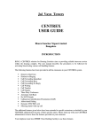
FONT A -- ABCDwxyz 12345
FONT B -- ABCDWXYZ 12345
FONT D -- ABCDwxyz 12345
FONT E -- (OCR-B) ABCDwxyz 12345
FONT F -- ABCDwxyz 12345
FONT G
--
Az 4
FONT H -- (OCR-A) UPPER CASE ONLY
FONT 0
-- (Scalable) ABCD wxyz 12345
FONT GS
--
R
C
FONT P--
ABCDwxyz 12345
FONT Q--
ABCDwxyz 12345
FONT R-- A B C D w x y z 1 2 3 4 5
FONT S-- A B C D w x y z 1 2 3 4 5
FONT T--
A B C Dw x y z 1 2 3 4 5
FONT U--
A B C Dw x y z 1 2 3 4 5
FONT V--
A B C Dwxyz 1 2 3 4 5
Figure 1-1. Default Fonts Examples
Page 1-4
Z4M/Z6M Maintenance Manual
77259L Rev. 4 12/16/03
6\VWHP'HVFULSWLRQ
6HFWLRQ
0HGLDVSHFLILFDWLRQV
Media Specifications
Minimum label length
Z4M
Z6M
Tear-off
0.5″ (13 mm)
0.5″ (13 mm)
Peel-off
1″ (25.4 mm)
1″ (25.4 mm)
Cutter
1″ (25.4 mm)
1″ (25.4 mm)
Rewind
0.5″ (13 mm)
0.5″ (13 mm)
39″ (991 mm)
Maximum
Minimum
1″ (25.4 mm)
Total
media
Tear/Cutter 4.5″ (114 mm)
width
(Includes Maximum
Peel/
liner, if
4.25″ (108 mm)
Rewind
any)
39"″(991 mm) (203dpi)
2″ (737 mm) (300dpi)
2″ (51 mm)
7″" (178 mm)
6.75″ (171 mm)
0.0023″ (0.058 mm)
0.0023″ (0.058 mm)
0.010″ (0.25 mm)
0.010″ (0.25 mm)
Cutter maximum full-width media
0.010″ (0.25 mm)
thickness
0.010″ (0.25 mm)
Minimum
Total thickness
(includes liner, if any) Maximum
Roll media core inside diameter
3″ (76 mm)
3″ (76 mm)
Maximum roll diameter
8.0″ (203 mm)
8.0″ (203 mm)
Maximum fan-fold pack size
8″ L × 4.5" W × 6.2" H
8″ L × 7" W × 6.2" H
Minimum
0.079″ (2 mm)
0.079″ (2 mm)
Preferred
0.118″ (3 mm)
0.118″ (3 mm)
Maximum
0.157″ (4 mm)
0.157″ (4 mm)
0.25″ × 0.12″
(6 mm × 3 mm)
0.25″ × 0.12"
(6 mm × 3 mm)
Inter-label gap
Ticket/tag sensing notch W × L
Ticket/tag sensing hole diameter 0.125″ (3mm)
Mark
Minimum
length
(measurin
g parallel Maximum
Mark width (measuring
Additional perpendicular to label/
specs. for tag edge)
black
Mark location
mark
sensing
Mark density
0.125″ (3mm)
0.098″ (2.5 mm)
0.098″ (2.5 mm)
0.453″ (11.5 mm)
0.453″ (11.5 mm)
≥ 0.37″ (≥ 9.5 mm)
≥ 0.37″ (≥ 9.5 mm)
Within 0.040″ (1 mm) of
inside media edge
Within 0.040″ (1 mm) of
inside media edge
> 1.0 Optical Density Units > 1.0 Optical Density Units
(ODU)
(ODU)
Maximum density of
the back of the media
0.5 ODU
on which the black
mark is printed
0.5 ODU
* Media registration and minimum label length are affected by media type and width, ribbon type, print speed, and
printer mode of operation. Performance improves as these factors are optimized. Zebra recommends always
qualifying any application with thorough testing.
77259L Rev. 4 12/16/03
Z4M/Z6M Maintenance Manual
Page 1-5
6HFWLRQ
6\VWHP'HVFULSWLRQ
5LEERQ6SHFLILFDWLRQV
Ribbon Specifications
Z4M
Z6M
Minimum
2″
51 mm
2″
51 mm
Maximum
4.3″
109 mm
6.85″
174 mm
2:1 media to
ribbon roll ratio
984′
300 m
984′
300 m
3:1 media to
ribbon roll ratio
1476′
450 m
1476′
450 m
Maximum ribbon roll size (outer diameter)
3.2″
(81.3 mm) 3.2″
(81.3 mm)
Inner diameter of core
1″
25.4 mm 1″
25.4 mm
Ribbon Width (To protect
the printhead from wear,
Zebra recommends using
ribbon at least as wide as
the media you are using.)
Standard lengths
Ribbon must be wound with the coated side out.
3ULQWHU6SHFLILFDWLRQV
Printing
Specifications
Z4M
203 dots/inch
8 dots/mm
Resolution
203 dots/inch
8 dots/mm
Dot size (square)
0.0049″ × 0.0049″ 0.0033″ × 0.0039″ 0.0049″ × 0.0049″ 0.0033″ × 0.0039″
0.125 × 0.125 mm 0.084 × 0.99 mm 0.125 × 0.125 mm 0.084 × 0.99 mm
First dot location
0.10″ ± 0.035″
0.12″ ± 0.035″
2.5 mm ±.89 mm 3 mm ±.89 mm
0.10″ ± 0.035″
0.12″ ± 0.035″
2.5 mm ±.89 mm 3 mm ±.89 mm
Max print width
4.1″
104 mm
6.6"
Minimum print length
1 dot row
203 dpi 105″
2667 mm
65″
1651 mm
300 dpi 49″
1245 mm
29"
737 mm
Print length (max)
300 dots/inch
12 dots/mm
Z6M
300 dots/inch
12 dots/mm
168 mm
203 dpi
Picket
Fence 4.9 mil to 49 mil
and
Bar code modulus Ladder
300 dpi
(“X”) dimension
Picket
3.3 mil to 33mil
Fence
300 dpi
3.9 mil to 39 mil
Ladder
Programmable
constant print
speeds
203
and
Per second: 2″, 3″, 4″, 5″, 6″
300 dpi
Per second:
51 mm, 76 mm, 102 mm, 127 mm,
152 mm
Add'l.
Per second: 7″, 8″, 9″, 10″
203 dpi
Per second:
178 mm, 203 mm, 229 mm, 254 mm
Thin film printhead with Element Energy Equalizer
Page 1-6
Z4M/Z6M Maintenance Manual
77259L Rev. 4 12/16/03
6\VWHP'HVFULSWLRQ
6HFWLRQ
*HQHUDO6SHFLILFDWLRQV
Physical Characteristics
Z4M
Z6M
Height
13.32"
338 mm
13.32"
338 mm
Width
10.93"
278 mm
13.43"
341 mm
Depth
18.69"
475 mm
18.69"
475 mm
Weight (without options)
32.4 lbs.
15 kg
34.7 lbs.
16 kg
(OHFWULFDO5HTXLUHPHQWV
•
Autoselect 90-264 VAC; 48-62 Hz
•
5 Amps for entire AC voltage range
•
2 5 Watts standby power consumption
•
200/300/350/450 Watts maximum power consumption for Z4M/Z6M. (printing
100% black at 6 ips)
•
UL 1950 Listed - Certified to CAN/CSA-C22.2 No. 950-M89 and IEC 950
•
Complies with CISPR22B and with FCC and Canadian DOC class “A” rules
•
Carries the CE mark of compliance
(QYLURQPHQWDO2SHUDWLQJ5DQJHV
Temperature
Non-condensing relative
humidity
77259L Rev. 4 12/16/03
Operating
Thermal Transfer: +40oF to +104oF (+5oC to +40oC)
Direct Thermal: +32oF to +104oF (0oC to +40oC)
Storage
-40oF to +140oF (-40oC to +60oC)
Operating
20% to 85%
Storage
5% to 85%
Z4M/Z6M Maintenance Manual
Page 1-7
6HFWLRQ
6\VWHP'HVFULSWLRQ
&RPPXQLFDWLRQ6SHFLILFDWLRQV
6HULDO'DWD&RPPXQLFDWLRQ,QWHUIDFH2YHUYLHZ
The Zebra Z4M/Z6M has a single data terminal equipment (DTE) port that supports RS232, RS-422 and RS-485 serial data communications. Baud rate, parity, data length, stop
bits, and XON/XOFF or DTR control protocols are front panel selectable. Refer to Figure
1-2. A 25-pin DB25S connector at the rear of the printer provides the data and control
leads necessary to communicate through all three signaling methods. The method used is
specific to the application of the printer.
For all RS-232 data and control input and output signals, the Zebra Z4M/Z6M follows
both the Electronic Industries Association’s (EIA) RS-232 and the Consultative
Committee for International Telegraph and Telephone (CCITT) V.24 specifications.
AC Power Switch
Back
Cover
AC Connector
Figure 1-2. Interface Connections
Page 1-8
Z4M/Z6M Maintenance Manual
77259L Rev. 4 12/16/03
6\VWHP'HVFULSWLRQ
6HFWLRQ
&RPPXQLFDWLRQ%XIIHU
The Z4M/Z6M printers have a communication buffer that stores the incoming data until
that information can be acted upon (imaged). Communication handshaking (DTR/DSR
control signals or XON/XOFF control codes) is used to control when the host can send
data to the printer.
The size of the buffer is 5000 characters. As data is received by the printer, the processor
monitors the number of characters in the buffer. If the buffer is filled beyond 4744
characters, the printer will turn the DTR control lead to the OFF condition (negative
voltage) or transmit an XOFF (DC-3) control character to the host. When the buffer
empties below 4250 characters, the printer will turn DTR to the ON condition (positive
voltage) or transmit an XON (DC-1) control character to the host.
6WDQGDUG6HULDO&RPPXQLFDWLRQ&RQQHFWRU
The DTE port is a DB25S connector located at the rear of the Z4M/Z6M printers. It
provides connection to a host via RS-232, RS-422 or RS-485 signaling. Refer to Figure
1-2 for wiring diagrams.
The pin outs and signal descriptions for the DTE port are as follows:
Pin 1—FG (Frame ground) for cable shield.
Pin 2—TXD (RS-232 Transmit Data): Output from printer
Pin 3—RXD (RS-232 Receive Data): Input to printer
Pin 4—RTS (RS-232 Request to Send): Output from printer
Pin 6—DSR (RS-232 Data Set Ready): Input to printer
Pin 7—SG (Signal ground) for RS-232
Pin 9—+5VDC source (1 Amp maximum)
Pin 11—SGR (Signal ground reference) RS-422/RS-485
Pin 13—Data input B(-) RS-422/RS-485
Pin 14—Data output B(-) RS-422/RS-485
Pin 16—Data input A(+) RS-422/RS-485
Pin 19—Data output A(+) RS-422/RS-485
Pin 20—DTR (RS-232 Data Terminal Ready)
Note • Pins 5, 8, 10, 12, 15, 17-18 and 21-25 are not used and are not
terminated.
77259L Rev. 4 12/16/03
Z4M/Z6M Maintenance Manual
Page 1-9
6HFWLRQ
6\VWHP'HVFULSWLRQ
6HULDO&RPPXQLFDWLRQ6LJQDO/HYHOV
Refer to Figure 1-3. RS-232 data signals are defined as either Mark or Space, while
control signals are ON (Active-Positive Voltage) or OFF (Inactive-Negative Voltage).
Although the permitted voltage levels can range from ±3VDC to ±25VDC, the levels for
the Z4M/Z6M printer are as follows:
RS-232 Transmit and Receive Data
Mark or OFF = -7 to -10 VDC Space or ON = +7 to +10 VDC
{
+Space
Parity
Bit
{
Data Bits
{
Start
Bit
0 Vdc
1
6
5
4
7
(idle)
{
- Mark
3
2
(idle)
Logic 1
Stop
Bit
Logic 0
Figure 1-3. RS-232 Signaling
Refer to Figure 1-4. RS-422 and RS-485 data signals are also either Mark or Space. The
voltage levels are +5 VDC and 0 VDC when monitored from a specified reference point.
The levels for the Z4M and Z6M printer, when referenced to signal ground are:
RS-422 and RS-485 Transmit and Receive Data
Mark
Output/Input A = +5V and Output/Input B = 0VSpace
and Output/Input B = +5V
Output/Input A = 0V
Logic 0
Stop
Bit
Logic 1
Mark
(+5 VDC)
(Idle)
(Idle)
1
2
3
4
5
6
7
(0 VDC)
Space
Start
Bit
Data Bits
Figure 1-4.
Page 1-10
Parity
Bit
RS-422/RS-485 Signaling
Z4M/Z6M Maintenance Manual
77259L Rev. 4 12/16/03
6\VWHP'HVFULSWLRQ
6HFWLRQ
&RPPXQLFDWLRQ&RGH
The Z4M/Z6M printer sends and receives ASCII (American Standard Code for
Information Interchange) characters in one of two formats, Serial Data or Parallel Data.
Note • When using the serial data format, the baud rate, number of data and
stop bits per character, and parity are selectable. Parity only applies to data
transmitted by the printer. For received data, the parity bit is ignored.
3DUDOOHO'DWD&RPPXQLFDWLRQV,QWHUIDFH2YHUYLHZ
A standard 36-pin parallel connector is available at the rear of the printer for connection to
the data source. Under normal circumstances, data sent from the printer to the host in
response to a “Printer Status Request” command is sent through the RS-232 serial port.
However, if the host has a properly configured IEEE-1284 parallel port that is recognized
by the printer, status information will be returned through the parallel port. Port selection
for status information is determined each time the printer is turned on.
3DUDOOHO3RUW&RQQHFWRU
The following table shows the pin configuration and function of a standard PC-to-Printer
Centronics® Parallel cable.
Note • Optional Ethernet Networking Communications via ZebraNet
PrintServer II. Refer to the ZebraNet Networking: PrintServer II Operating
Guide (45537L) when using this communications option.
77259L Rev. 4 12/16/03
Z4M/Z6M Maintenance Manual
Page 1-11
6HFWLRQ
6\VWHP'HVFULSWLRQ
36-pin Connector
Description
1
nStrobe/HostClk
2-9
Data Bits 1-8
10
nACK/PtrClk
11
Busy/PtrBusy
12
PError/ACKDataReq
13
Select/Xflag
14
nAutoFd/HostBusy
15
Not Used
16 & 17
Ground
18
+5V @ 1A
19-30
Ground
31
ninit
32
nFault/NDataAvail
33 & 34
Not Used
35
+5V through a 4.7 KW Resistor
36
NSelectIn/1284 active
2SWLRQDO,QWHUIDFH%RDUGV
For information about the IBM® plug-compatible Twinax Interface, the IBM plugcompatible Coax Interface, the RS-485 network interface, refer to the instructions that
accompany the interface option kits.
'$7$6WDWXV,QGLFDWRU
ON indicates that data processing or printing is taking place, but no data is being received.
OFF indicates that no data is being received or processed. FLASHING indicates that data
is being received. (Flashing slows down when the printer is unable to accept any more
data due to the data input buffer being full. Flashing returns to normal rate when the data
input buffer is no longer full and data is again being received.)
Page 1-12
Z4M/Z6M Maintenance Manual
77259L Rev. 4 12/16/03
2SHUDWLRQV2YHUYLHZ
6HFWLRQ
6HFWLRQ
2SHUDWLRQV2YHUYLHZ
,QVWDOODWLRQ
Following is a detailed description of the installation procedures for the printer.
8QSDFN3ULQWHU
Save the carton and all packing materials in case shipping is ever required. Inspect the
printer for possible damage incurred during shipment.
Check all exterior surfaces for damage.
Raise the media access door and inspect the media compartment for damage to
components.
If you discover shipping damage:
Immediately notify the shipping company of the damage. Retain the carton and all
packaging material for shipping company inspection. File a damage report with the
shipping company and notify your local Zebra distributor of the damage.
Zebra Technologies is not responsible for any damage incurred during shipment of the
printer and will not cover the repair of this damage under its warranty policy. Any damage
claim should be filed with the shipping company.
6WRUDJHDQG5HVKLS
If you are not placing the Z4M or Z6M printer into operation immediately, repackage it
using the original packing materials. The printer may be stored under the following
conditions:
•
Temperature: -40º to 140º F (-40º TO 60º C)
•
Relative humidity: 5% to 85% non-condensing.
To ship the printer, remove all ribbon and media from the supply and take-up spindles to
prevent damage to the printer. Carefully pack the printer in a suitable container to avoid
damage during transit. Whenever possible, use the original container from the factory. If
the original one is lost or destroyed, a shipping container can be purchased from Zebra
Technologies Corporation.
If you use a different container, package the printer carefully to avoid damage.
Note • When packaging the printer in a rigid container, use shock mounts or
shock-absorbing packing material.
77259L Rev. 4 12/16/03
Z4M/Z6M Maintenance Manual
Page 2-1
6HFWLRQ
2SHUDWLRQV2YHUYLHZ
2SHUDWRU&RQWUROV
This section discusses the functions of the various controls and indicators on the printer.
The operator should become familiar with each of these functions.
)URQW3DQHO'LVSOD\
The front panel display communicates operational and programming modes and
parameters.
PAUSE
Figure 2-1. Location of Control Panel Keys
Page 2-2
Z4M/Z6M Maintenance Manual
77259L Rev. 4 12/16/03
2SHUDWLRQV2YHUYLHZ
6HFWLRQ
)URQW3DQHO.H\V
Key
Function
Forces the printer to feed one blank label each time the key is pressed.
• Printer not printing: one blank label immediately feeds.
•
Printing: one blank label feeds after the current batch of labels is complete.
Note • Equivalent to the Slew to Home Position (~PH, ^PH) ZPL II instruction.
PAUSE
Stops and starts the printing process.
Printer not printing: no printing can occur.
Printing: printing stops once the current label is complete.
Press to remove error messages from the display.
Note • Pause Mode can also be activated via ZPL II (~PP, ^PP).
In pause mode cancels print jobs.
Printer not printing: the next stored label format is canceled.
Printing: the label format currently printing is canceled.
Press and hold for several seconds to cancel all print jobs in the printer’s memory.
Enters and exits the configuration mode.
Toggles increment (+) and decrement (-) between scroll and change.
Press once to increment (+) and decrement (-) value of the selection.
Press again to increment (+) and decrement (-) to scroll through the menu items.
Scrolls to the next selection.
Scroll Mode
Change Mode
Increases value.<
Answers yes.<
Prints a label (when applicable).
77259L Rev. 4 12/16/03
Z4M/Z6M Maintenance Manual
Page 2-3
6HFWLRQ
2SHUDWLRQV2YHUYLHZ
Scrolls to the previous selection.
Scroll Mode
Change Mode
Decreases the value.
Selects the digit you wish to change.
Answers no.
)URQW3DQHO/LJKWV
Light
Status
Indication
Off
Printer turned off or no power is applied.
On
Power applied and turned on.
Off
Normal printer operation.
On
Printer stopped all printing operations
Flashing
In peel-off mode, the PAUSE light flashes when the label is available
for removal. In all modes, flashes when initializing FLASH or PCMCIA
memory.
Off
Normal printer operation (no errors).
Slow flashing
“RIBBON IN” warning, “HEAD UNDER TEMP” warning, or “HEAD
OVER TEMP” error
Fast flashing
“HEAD OPEN” error
On
“PAPER OUT,” “RIBBON OUT,” or “CUTTER JAM” errors
Off
Normal printer operation (no data being received or processed).
One flash
The CANCEL key is pressed and a format is successfully canceled.
Slow flashing
The printer is unable to accept more data from the host.
Fast flashing
The printer is receiving data.
On
A complete format has been received and there has been no
subsequent data activity.
/RDG0HGLDDQG5LEERQ
/RDG5LEERQ
Note • The ribbon supply spindle in your printer is a "dual tension" variety. Most
applications require the spindle to be in the "normal" position. The "low tension"
position is recommended only when wide ribbon is used and normal tension
hampers the ribbon movement.
Page 2-4
Z4M/Z6M Maintenance Manual
77259L Rev. 4 12/16/03
2SHUDWLRQV2YHUYLHZ
6HFWLRQ
To place this spindle in the "normal" position, firmly pull out the spindle end segment
(plastic part only) until it clicks into place as shown in Figure 2-2. To place the spindle in
the "low tension" position, firmly push in the spindle end segment until it clicks into place.
Refer to Figure 2-2.
1.
Press the printhead open lever. The printhead assembly springs up.
2.
Push the ribbon roll completely onto the ribbon supply spindle.
3.
Pull the end of the ribbon over the ribbon sensor, under the printhead assembly, and
out the front of the printer.
4.
Close the printhead assembly, keeping the ribbon snug and free of wrinkles and in
line with the guide mark near the left edge of the ribbon guide plate.
5.
Wind the ribbon clockwise onto the ribbon take-up spindle.
Ribbon Take-up Spindle
Spindle End Cap
Extended
Ribbon
Guide Plate
Normal Position
Spindle End Cap
Retracted
Ribbon
Sensor
Ribbon
Supply Spindle
Low Tension Position
Printhead Open Lever
Figure 2-2. Ribbon Loading
5HPRYH5LEERQ
1.
Break the ribbon between the ribbon guide plate and the ribbon take-up spindle.
2.
While turning the ribbon take-up spindle release knob counterclockwise, squeeze
the ribbon against the ribbon take-up spindle tension blades.
3.
When the tension blades collapse into the ribbon take-up spindle, hold the release
knob and rotate the used ribbon toward the rear of the printer. Then, slide off the
ribbon.
/RDG0HGLD
Tear-Off Mode
Refer to Figure 2-3.
77259L Rev. 4 12/16/03
1.
Press the printhead open lever. The printhead assembly springs up.
2.
Flip down the media supply guide.
Z4M/Z6M Maintenance Manual
Page 2-5
6HFWLRQ
2SHUDWLRQV2YHUYLHZ
3.
Slide out the media guide as far from the printer frame as possible.
4.
Place the roll of media on the media supply hanger.
5.
Flip up the media supply guide. Slide in the media supply guide so that it just
touches, but does not restrict, the edge of the roll.
6.
Feed the media under the dancer, through the slot in the transmissive sensor, under
the ribbon sensor, and out the front of the printer.
7.
Ensure that the media is against the back of the transmissive sensor. Slide in the
media guide so that it just touches, but does not restrict, the edge of the media.
8.
Close the printhead assembly.
Ribbon
Sensor
Printhead
Assembly
Printhead Open Lever
Media Guide
Media Supply Guide
Transmissive
Sensor
Media
Supply
Hanger
Figure 2-3. Media Loading Tear Off Mode
Page 2-6
Z4M/Z6M Maintenance Manual
77259L Rev. 4 12/16/03
2SHUDWLRQV2YHUYLHZ
6HFWLRQ
Cutter Mode
(Cutter option required)
Refer to Figure 2-4.
1.
Press the printhead open lever. The printhead assembly springs up.
2.
Flip down the media supply guide.
3.
Slide the media guide out as far from the printer frame as possible.
4.
Place the roll of media on the media supply hanger.
5.
Flip up the media supply guide. Slide in the media supply guide so that it just
touches, but does not restrict, the edge of the roll.
6.
Feed the media under the dancer, through the slot in the transmissive sensor, under
the ribbon sensor, and through the cutter module.
7.
Ensure that the media is against the back of the transmissive sensor. Then, slide in
the media guide so that it just touches, but does not restrict, the edge of the media.
8.
Close the printhead assembly.
Ribbon
Sensor
Printhead
Assembly
Printhead Open Lever
Media Guide
Media Supply Guide
Transmissive
Sensor
Media
Supply
Hanger
Figure 2-4. Media Loading Cutter Mode
77259L Rev. 4 12/16/03
Z4M/Z6M Maintenance Manual
Page 2-7
6HFWLRQ
2SHUDWLRQV2YHUYLHZ
Value Peel-Off Mode
(Value peel option required)
Refer to Figure 2-5.
Page 2-8
1.
Press the printhead open lever. The printhead assembly springs up.
2.
Flip down the media supply guide.
3.
Slide out the media guide as far from the printer frame as possible.
4.
Place the roll of media on the media supply hanger.
5.
Flip up the media supply guide. Slide in the media supply guide so that it just
touches, but does not restrict, the edge of the roll.
6.
Feed the media under the dancer, through the slot in the transmissive sensor, and
under the ribbon sensor.
7.
Pull approximately 6” (305 mm) of media through the front of the printer.
8.
Ensure that the media is against the transmissive sensor. Then, slide in the media
guide so that it just touches, but does not restrict, the edge of the roll.
9.
Pull lever to open the pivot bracket assembly.
10.
Feed the media through the slot in the peel assembly.
11.
Close the printhead assembly.
12.
Close the pivot bracket assembly.
13.
Peeling will automatically start. Press the FEED key to test.
Z4M/Z6M Maintenance Manual
77259L Rev. 4 12/16/03
2SHUDWLRQV2YHUYLHZ
6HFWLRQ
Ribbon Sensor
Transmissive
Sensor
Dancer
Media Supply Guide
Printhead
Assembly
Lever
Label
Liner
Printhead
Open Lever
Media
Supply
Hanger
Media Guide
Media
Peel Bar
Figure 2-5. Media Loading Value Peel
77259L Rev. 4 12/16/03
Z4M/Z6M Maintenance Manual
Page 2-9
6HFWLRQ
2SHUDWLRQV2YHUYLHZ
Value Peel-Off Mode with Liner Take-up
Note • Liner Take-up only available on Z4M.
Refer to Figure 2-5.
Page 2-10
1.
Press the printhead open lever. The printhead assembly springs up.
2.
Flip down the media supply guide.
3.
Slide out the media supply guide as far from the printer frame as possible.
4.
Place the roll of media on the media supply hanger.
5.
Flip up the media supply guide. Slide in the media supply guide so that it just
touches, but does not restrict, the edge of the roll.
6.
Feed the media under the dancer, through the slot in the transmissive sensor, and
under the ribbon sensor.
7.
Pull approximately 18” (500 mm) of media through the front of the printer.
8.
Remove the labels from the 18” of media so that only the liner remains.
9.
Ensure that the media is against the back of the transmissive sensor. Then, slide in
the media guide so that it just touches, but does not restrict, the edge of the media.
10.
Pull down the lever to open the pivot bracket assembly on the peel assembly.
11.
Feed the media over the tear-off/peel-off bar and behind the pivot bracket assembly.
12.
Close the printhead assembly.
13.
Close the pivot bracket assembly.
14.
Slide the liner into the slot in the
spindle (as shown). Make sure the
liner is resting against the back
plate of the spindle assembly.
15.
Turn the spindle assembly counterclockwise a few times so that the
liner is snug.
16.
Peeling will automatically start.
Press the FEED key to test.
Z4M/Z6M Maintenance Manual
77259L Rev. 4 12/16/03
2SHUDWLRQV2YHUYLHZ
6HFWLRQ
Ribbon Sensor
Transmissive
Sensor
Dancer
Media Supply Guide
Printhead
Assembly
Lever
Label
Printhead
Open Lever
Media Guide
Liner Take up
Media
Supply
Hanger
Figure 2-6. Media Loading Value Peel with Liner Take-up
Remove Liner
1.
Using the liner slide tab, pull the
liner slide towards you (as
shown) until it stops (about a
third of the way down the liner
take-up spindle).
2.
Slide the liner from the take-up
spindle.
Liner Slide
Note • The liner slide should move smoothly back into place once the liner has
been removed.
77259L Rev. 4 12/16/03
Z4M/Z6M Maintenance Manual
Page 2-11
6HFWLRQ
2SHUDWLRQV2YHUYLHZ
Value Peel Rewind (Peel-off Mode)
Note • Value peel option is replacing the power peel option.
Refer to Figure 2-7
Page 2-12
1.
Press the printhead open lever. The printhead assembly springs up.
2.
Flip down the media supply guide.
3.
Slide out the media supply guide as far from the printer frame as possible.
4.
Place the roll of media on the media supply hanger.
5.
Flip up the media supply guide. Slide in the media supply guide so that it just
touches, but does not restrict, the edge of the roll.
6.
Feed the media under the dancer, through the slot in the transmissive sensor, and
under the ribbon sensor.
7.
Pull approximately 36” (1 m) of media through the front of the printer
8.
Remove the labels from about 18” of media so that only the liner remains.
9.
Ensure that the media is against the back of the transmissive sensor. Then, slide in
the media guide so that it just touches, but does not restrict, the edge of the media.
10.
Pull down the lever to open the pivot bracket assembly on the peel assembly.
11.
Feed the media over the tear-off/peel-off bar and behind the pivot bracket assembly.
12.
Close the printhead assembly.
13.
Close the pivot bracket assembly.
14.
Loosen the thumbscrew and slide out the rewind media guide to the end of the takeup spindle.
15.
Wrap the liner around a core placed on the take-up spindle; then, turn the take-up
spindle counterclockwise to wind up the excess liner material.
16.
Slide the rewind media guide against the liner material and tighten the thumbscrew
to lock it into position.
17.
Peeling will automatically start. Press the FEED key to test.
Z4M/Z6M Maintenance Manual
77259L Rev. 4 12/16/03
2SHUDWLRQV2YHUYLHZ
6HFWLRQ
Ribbon
Sensor
Media Supply Guide
Printhead
Assembly
Lever
Media
Supply
Hanger
Dancer
Label
Printhead
Open Lever
Media
Alignment
Spindle
Take-up
Spindle
Media
Guide
Transmissive Thumbscrew
Sensor
Rewind
Media
Guide
Figure 2-7. Value Peel Rewind (Peel-Off Mode)
Value Peel Rewind (Rewind Mode)
Refer to Figure 2-8.
77259L Rev. 4 12/16/03
1.
Press the printhead open lever. The printhead assembly springs up.
2.
Flip down the media supply guide.
3.
Slide out the media supply guide as far from the printer frame as possible.
4.
Place the roll of media on the media supply hanger.
5.
Flip up the media supply guide. Slide in the media supply guide so that it just
touches, but does not restrict, the edge of the roll.
6.
Feed the media under the dancer, through the slot in the transmissive sensor, and
under the ribbon sensor.
7.
Pull approximately 36” (1 m) of media through the front of the printer
8.
Remove the labels from about 18” of media so that only the liner remains.
9.
Ensure that the media is against the back of the transmissive sensor. Then, slide in
the media guide so that it just touches, but does not restrict, the edge of the media.
10.
Feed the media over the value peel assembly, through the rewind base
11.
Loosen the thumbscrew and slide out the rewind media guide to the end of the takeup spindle.
12.
Wrap the media around a core placed on the take-up spindle; then turn the take-up
spindle counterclockwise to wind up the excess material.
Z4M/Z6M Maintenance Manual
Page 2-13
6HFWLRQ
2SHUDWLRQV2YHUYLHZ
13.
Slide the rewind media guide against the media, and tighten the thumbscrew to lock
it into position.
14.
Close the printhead assembly.
Ribbon
Sensor
Printhead
Assembly
Media Supply Guide
Lever
Media
Supply
Hanger
Dancer
Take-up
Spindle
Printhead
Open Lever
Media
Alignment
Spindle
Media Transmissive
Guide
Sensor
Rewind
Media
Guide
Thumbscrew
Figure 2-8. Value Peel Rewind (Rewind Mode)
Page 2-14
Z4M/Z6M Maintenance Manual
77259L Rev. 4 12/16/03
2SHUDWLRQV2YHUYLHZ
6HFWLRQ
Value Peel Rewind Media Alignment
Note • The media/liner should be installed flush against the back plate of the
take-up spindle to prevent the media/liner from winding too loosely.
Perform the following adjustment if the media does not track properly onto the take-up
spindle.
1.
Refer to Figure 2-9. Turn the adjustment dial clockwise to align the media/liner
material toward the inboard (i.e., main frame or electronics) side. This is the most
likely adjustment.
or
2.
Turn the dial counterclockwise to align the media/liner material toward the outboard
side (i.e., away from the main frame or electronics side).
Printhead
Assembly
Backplate
Adjustment
Dial
Take-up
Spindle
Figure 2-9. Value Peel Rewind Media Adjustment
Power Peel-off Mode
Note • Power peel-off option required. (Being replaced with value peel/rewind
option).
Refer to Figure 2-10.
77259L Rev. 4 12/16/03
1.
Press the printhead open lever. The printhead assembly springs up.
2.
Flip down the media supply guide.
3.
Slide out the media supply guide as far from the printer frame as possible.
4.
Place the roll of media on the media supply hanger.
5.
Flip up the media supply guide. Slide in the media supply guide so that it just
touches, but does not restrict, the edge of the roll.
6.
Feed the media under the dancer, through the slot in the transmissive sensor, and
under the ribbon sensor.
7.
Pull approximately 36” (1 m) of media through the front of the printer.
Z4M/Z6M Maintenance Manual
Page 2-15
6HFWLRQ
2SHUDWLRQV2YHUYLHZ
8.
Ensure that the media is against the back of the transmissive sensor. Then, slide in
the media guide so that it just touches, but does not restrict, the edge of the media.
9.
Open the front housing assembly by lifting the handles; then, pivot down the front
housing assembly.
10.
Remove at least 12” (305 mm) of labels from the liner material.
11.
Feed the liner material over the tear-off/peel-off bar, through the rectangular cutout
in the mounting bracket, and under the media alignment spindle.
12.
Close the front housing assembly by slightly lifting and then hooking it onto the
pins on the tear-off/peel-off bar.
13.
Loosen the thumbscrew and slide out the rewind media guide to the end of the takeup spindle.
14.
Wrap the liner around a core placed on the take-up spindle; then, turn the take-up
spindle counterclockwise to wind up the excess liner material.
15.
Slide the rewind media guide against the liner material and tighten the thumbscrew
to lock it into position.
16.
Close the front housing assembly.
17.
Close the printhead assembly.
Printhead
Assembly
Transmissive
Sensor
Dancer
Media Supply Guide
Tear-Off
Peel-off
Bar
Front
Housing
Assembly
Label
Media
Supply
Hanger
Take-up
Spindle
Printhead
Open Lever
Ribbon
Sensor
Media
Alignment
Spindle
Media
Guide
Thumbscrew
Rewind
Media
Guide
Figure 2-10. Power Peel Loading
Liner Removal
Page 2-16
1.
Cut the liner material prior to where it winds onto the take-up spindle.
2.
Rotate the take-up spindle until the rewind media guide is in the “12 o’clock”
position.
Z4M/Z6M Maintenance Manual
77259L Rev. 4 12/16/03
2SHUDWLRQV2YHUYLHZ
6HFWLRQ
3.
Loosen the thumbscrew, slide the rewind media guide to the end of the take-up
spindle and flip the media guide horizontal.
4.
Slide the core and liner material from the take-up spindle.
Power Rewind Mode
Note • Power peel-off option required. (Being replaced with value peel/rewind
option).
Refer to Figure 2-11.
77259L Rev. 4 12/16/03
1.
Press the printhead open lever. The printhead assembly springs up.
2.
Flip down the media supply guide.
3.
Slide out the media supply guide as far from the printer frame as possible.
4.
Place the roll of media on the media supply hanger.
5.
Flip up the media supply guide. Slide in the media supply guide so that it just
touches, but does not restrict, the edge of the roll.
6.
Feed the media under the dancer, through the slot in the transmissive sensor, and
under the ribbon sensor.
7.
Pull approximately 36” (1 m) of media through the front of the printer.
8.
Ensure that the media is against the back of the transmissive sensor. Then, slide in
the media guide so that it just touches, but does not restrict, the edge of the media.
9.
Feed the media over the front housing assembly, through the rewind base, and under
the media alignment spindle.
10.
Loosen the thumbscrew and slide out the rewind media guide to the end of the takeup spindle.
11.
Wrap the media around a core placed on the take-up spindle; then, turn the take-up
spindle counterclockwise to wind up the excess material.
12.
Slide the rewind media guide against the media, and tighten the thumbscrew to lock
it into position.
13.
Close the printhead assembly.
Z4M/Z6M Maintenance Manual
Page 2-17
6HFWLRQ
2SHUDWLRQV2YHUYLHZ
Printhead
Assembly
Transmissive
Dancer Media Supply Guide
Sensor
Front
Housing
Assembly
Media
Supply
Hanger
Take-up
Spindle
Printhead
Open Lever
Media
Ribbon
Sensor Alignment
Spindle
Rewind
Media
Guide
Media
Guide
Thumbscrew
Figure 2-11. Power Rewind Loading
Media Removal
Page 2-18
1.
Cut the media prior to where it ends on the take-up spindle.
2.
Rotate the take-up spindle until the rewind media guide is in the “12 o’clock”
position.
3.
Loosen the thumbscrew, slide the rewind media guide to the end of the take-up
spindle and flip the media guide horizontal.
4.
Slide the core and roll of media from the take-up spindle.
Z4M/Z6M Maintenance Manual
77259L Rev. 4 12/16/03
2SHUDWLRQV2YHUYLHZ
6HFWLRQ
Power Peel Rewind Media Alignment
Note • The media liner should be installed flush against the back plate of the
take-up spindle to prevent the media/liner from winding too loosely.
Perform the following adjustment if the media does not track properly onto the take-up
spindle.
1.
Refer to Figure 2-12. Turn the adjustment dial clockwise to align the media/liner
material toward the inboard (i.e., main frame or electronics) side. This is the most
likely adjustment.
or
2.
Turn the dial counterclockwise to align the media/liner material toward the outboard
side (i.e., away from the main frame or electronics side).
Printhead
Assembly
Take-up
Spindle
Adjustment
Dial
Figure 2-12. Media Alignment (Rewind Shown)
77259L Rev. 4 12/16/03
Z4M/Z6M Maintenance Manual
Page 2-19
6HFWLRQ
2SHUDWLRQV2YHUYLHZ
Fanfold Media Loading
Fanfold media feeds through either the bottom or rear access slot. The lower rear cover
guide surface can be used as a reference to align media in printer.
Refer to Figure 2-13.
Page 2-20
1.
Press the printhead open lever. The printhead assembly springs up.
2.
Flip down the media supply guide.
3.
Slide out the media guide as far from the printer frame as possible.
4.
Pass the fanfold media over the media supply hanger.
5.
Flip up the media supply guide. Slide in the media supply guide so that it just
touches, but does not restrict, the edge of the media.
6.
Thread the media under the dancer, through the slot in the transmissive sensor,
under the ribbon sensor, and out the front of the printer.
7.
Ensure that the media is against the back of the transmissive sensor. Then, slide in
the media guide so that it just touches, but does not restrict, the edge of the media.
8.
Close the printhead assembly.
Z4M/Z6M Maintenance Manual
77259L Rev. 4 12/16/03
2SHUDWLRQV2YHUYLHZ
6HFWLRQ
Media Supply Guide
Printhead
Assembly
Printhead
Open Lever
Media Guide
Rear Slot Feed
Media
Supply
Hanger
Media Supply Guide
Printhead
Assembly
Printhead
Open Lever
Media Guide
Bottom Feed
Media
Supply
Hanger
Figure 2-13. Media Loading Fanfold
77259L Rev. 4 12/16/03
Z4M/Z6M Maintenance Manual
Page 2-21
6HFWLRQ
2SHUDWLRQV2YHUYLHZ
Note • Placing an empty 3” core on the hanger will assist the media movement.
$OLJQ6HQVRUV
7UDQVPLVVLYH6HQVRU
There is no positioning of the transmissive sensor. All media is to be loaded through the
transmissive sensor as described in the media and ribbon loading chapters.
Note • The transmissive sensor should not be used when the sensor type is
set to MARK. If the transmissive sensor is the active sensor when the sensor
type is changed from WEB to MARK, an auto-calibration is initiated to make the
reflective sensor active.
The transmissive sensor should not be used when the media type is set to
Continuous. If the transmissive sensor is the active sensor when the media
type is changed from Noncontinuous to Continuous, and auto-calibration is
initiated to make the reflective sensor active.
6HOHFWLQJWKH0HGLD6HQVRU
A Z4M/Z6M printer can be configured to select either of the sensors. By default the printer
is set to AUTO SELECT during auto-calibration.
Note • Changing the SENSOR SELECT setting via the front panel will initiate
an auto-calibration.
The SENSOR SELECT setting may also be changed via ZPL II®. The format for the ^JS
instruction is as follows:
^JSx
Where
^JS=Sensor Select
x=Type of sensor
A=Auto Select
R=Reflective Sensor
T=Transmissive Sensor
Note • Changing the SENSOR SELECT setting via ZPL II will initiate an
auto-calibration.
The sensor can be selected from the LCD menu (see User’s Guide).
Page 2-22
Z4M/Z6M Maintenance Manual
77259L Rev. 4 12/16/03
2SHUDWLRQV2YHUYLHZ
6HFWLRQ
0HGLDDQG0HGLD6HQVRU&RQVLGHUDWLRQV
It is important that the appropriate media sensor is selected for the type media being used.
If the Transmissive Sensor is set to Auto Select mode and an auto-calibration condition
occurs (see media calibration), the appropriate media sensor will be selected. If Sensor
Select is set for Reflective Sensor or Transmissive Sensor, the auto-calibration will
calibrate the selected Media Sensor and ignore the other.
The trade-off between using Auto Select instead of the Reflective Sensor or Transmissive
Sensor is an increased time to print the first label. If the Sensor Select is set for Reflective
Sensor or Transmissive Sensor, the autocalibration will take longer to complete because it
is determining which media sensor to activate.
•
Reflective sensor type media – Non-continuous (labels, notched tags) media
This type of media has some type of physical characteristic (notch, black mark, gap
between die-cut labels etc.) which indicates the start-of-label position. The reflective
sensor must be properly positioned to sense these indicators.
•
Transmissive sensor type media – Pre-printer liners, thick and opaque liners or
dark adhesive sided media
This type of media requires the use of the transmissive sensor. The reflective sensor will
not properly calibrate with this type of media.
$XWR&DOLEUDWH
The autocalibration of the Z4M/Z6M printer occurs at power-on and each time the printer
recovers from error conditions such as media errors, ribbon errors and printhead open
errors. When clearing an error, open and close the printhead and take the printer out of
pause. The printer will begin the autocalibration process if all errors have been cleared.
During autocalibration, the printer automatically determines the label length, media and
ribbon sensor settings. When non-continuous media is sensed, the calibration process is
followed by the label length calculation. Once the label length is determined, the media
feeds to the rest position and stops.
The results of this calibration are stored in the printer’s memory and retained even if
printer power is removed. These parameters remain in effect until the next calibration is
performed.
&DOLEUDWH&RQWURO
The autocalibration process will not take place if the ZPL command or the front panel
setting for “Media Power Up” or “Head Close” is set to “no motion.” If set to “feed” the
printer will feed until the first sensed gap, notch or mark passes the tear off bar. In these
cases, the printer assumes the media is correctly positioned and starts printing without
calibrating.
As long as the printhead is closed, calibration may be performed. Calibration may clear
error conditions that prevent media movement. Unless an out-of-ribbon or out-of-media
condition exists, ribbon and media error conditions are cleared by calibration.
77259L Rev. 4 12/16/03
Z4M/Z6M Maintenance Manual
Page 2-23
6HFWLRQ
2SHUDWLRQV2YHUYLHZ
3ULQWHU6HOI7HVWV
The Z4M/Z6M printer is designed to work with most Zebra media and ribbon
combinations. However, in some applications, changes to the printer’s configuration and
mechanical settings may be required. For these situations, printer self test labels can be
used to check print quality and ensure proper operation.
These self tests produce sample printouts and provide specific information that determines
the operating conditions for the printer.
Each self test can be enabled from the LCD Menu. Hold the – key and turn power On (l)
to access the menu.
Note • When performing self tests, disconnect all data interface cables from
the printer.
When canceling a self-test before it’s actual completion, always turn the printer
power OFF and then back ON to reset the printer.
When performing these self tests while in the peel mode, you must remove the
labels as they become available.
For self test Zebra recommends using full with media. Make sure that your print
width is set correctly for the media you are using before you run any self tests,
otherwise the test may print out on the platen.
&DQFHO.H\6HOI7HVW
Press and hold CANCEL while turning the printer power On (l). Release the key anytime
after the first front panel LED turns off. The Cancel Key Self Test prints a configuration
label showing:
•
Printer Configuration.
•
Installed Options.
•
Software Version.
•
Copyright Notice.
Figure 2-14 shows an example of the printer configuration label. The configuration
information will print over several labels if a label is not long enough to display all of the
configuration information at one time.
Page 2-24
Z4M/Z6M Maintenance Manual
77259L Rev. 4 12/16/03
2SHUDWLRQV2YHUYLHZ
6HFWLRQ
Figure 2-14. CANCEL Key Self Test Label (Configuration Label)
3DXVH.H\6HOI7HVW
Press and hold PAUSE while turning the printer power On (l). Release the key anytime
after the first front panel LED turns off. The Pause Key Self Test prints a series of labels
which can be used when making print quality adjustments.
9999 labels at two inches per second pausing every 15 labels.
9999 labels at six inches per second pausing every 15 labels.
9999 labels at two inches per second pausing every 50 labels.
9999 labels at six inches per second pausing every 50 labels.
9999 labels at ten inches per second pausing every 50 labels (200 dpi printers only)
When the printer pauses, press PAUSE to restart printing at the same speed. Pressing
CANCEL switches to the next set of labels.
Figure 2-15 provides an example of the Pause Key Self Test label.
77259L Rev. 4 12/16/03
Z4M/Z6M Maintenance Manual
Page 2-25
6HFWLRQ
2SHUDWLRQV2YHUYLHZ
Figure 2-15. PAUSE Key Self Test Label
)HHG.H\6HOI7HVW
Press and hold FEED while turning the printer power on (l). Release the key anytime after
the first front panel LED turns off.
The quantity of labels printed during this print quality test depends on the dot density of
the printhead.
300 dpi printers: 7 labels are printed at the 2 ips and 6 ips print speeds.
200 dpi printers: 7 labels are printed at the 2 ips, 6 ips and 10 ips print speeds.
Each label is printed at a different darkness setting, starting at three settings below the
current configured value and continuing to increase until it is three settings darker than the
configured value. The relative darkness and speed are printed on each label. The bar codes
on these labels can be ANSI-graded to check print quality.
Figure 2-16 provides an example of the Feed Key Self Test label.
Page 2-26
Z4M/Z6M Maintenance Manual
77259L Rev. 4 12/16/03
2SHUDWLRQV2YHUYLHZ
6HFWLRQ
Figure 2-16. FEED Key Self Test Label
3DXVHDQG&DQFHO.H\6HOI7HVW
Press and hold both PAUSE and CANCEL while turning the printer power On (l).
Release both keys anytime after the first front panel LED turns off.
The Pause and Cancel Key Self Test prints a series of 500 labels which can be used when
making print quality adjustments. The printed label will look like the PAUSE Key Self
Test label and will be sequentially numbered.
Figure 2-17 provides an example of PAUSE and CANCEL Self Test label.
Figure 2-17. PAUSE and CANCEL Key Self Test Label
77259L Rev. 4 12/16/03
Z4M/Z6M Maintenance Manual
Page 2-27
6HFWLRQ
2SHUDWLRQV2YHUYLHZ
3DXVHDQG)HHG.H\6HOI7HVW5HVHW'HIDXOWV
Press and hold both PAUSE and FEED while turning the printer On (l). Release both keys
anytime after the first front panel LED turns off.
PAUSE and FEED together reset the printer to the default settings. These values are not
saved in EEPROM, but may be saved by sending the ZPL command ^JUS or saving
through the LCD on the front panel. After entering factory defaults, the printer will remain
in the paused state to let the operator know that the defaults have been loaded.
&RPPXQLFDWLRQV'LDJQRVWLF6HOI7HVW
The communications diagnostic mode is a troubleshooting tool for checking the
interconnection between the printer and the host data device. When “Diagnostics” is
selected, all data sent to the printer will be printed as straight ASCII hex characters. The
printer prints all received characters including control codes like CR (Carriage Return).
To enter the communications diagnostics mode press and hold + while turning the printer
On (l). Release the key anytime after the first front panel LED turns off. You can also enter
enter the diagnostics mode by pressing the SETUP/EXIT and then + until you get to
communications. Press SELECT then enter the password, press + to change number and
– sign to move cursor.
Send a label format from the host data device to the printer and observe the printout on the
label stock. Figure 2-18 provides an example of the diagnostic mode printout.
Note • An FE indicates a framing error.
An OE indicates an overrun error.
An PE indicates a parity error.
An NE indicates noise.
If errors are indicated, verify your communication parameters are correct.
Page 2-28
Z4M/Z6M Maintenance Manual
77259L Rev. 4 12/16/03
2SHUDWLRQV2YHUYLHZ
6HFWLRQ
Figure 2-18. Communications Diagnostics Self Test
77259L Rev. 4 12/16/03
Z4M/Z6M Maintenance Manual
Page 2-29
6HFWLRQ
Page 2-30
2SHUDWLRQV2YHUYLHZ
Z4M/Z6M Maintenance Manual
77259L Rev. 4 12/16/03
7URXEOHVKRRWLQJ
6HFWLRQ
6HFWLRQ
7URXEOHVKRRWLQJ
*HQHUDO
Consult the following troubleshooting tables.
If you encounter any problems that cannot be corrected with the aid of this manual,
contact Zebra’s Technical Support immediately to minimize or avoid printer downtime.
Technical Support can also assist in determining if the printer should be returned for repair
(See Table 3-1 for Technical Support numbers).
Another service of Zebra, Technical Support via the Internet (ZIP Support™ http://
support.zebra.com), is also available 24 hours a day, 365 days a year.
Table 3-1. Technical Support Telephone Numbers
Zebra Technologies
333 Corporate Woods Parkway
Vernon Hills, Illinois 60061-3109
Phone: (847)-913-2259
Fax: (847) 913-2578
Zebra Technologies Europe Limited, UK
Zebra House,
Unit 14, The Valley Centre, Gordon Road
High Wycombe, Buckinghamshire, HP13 6EQ,
UK
Phone: +44 (0) 1494 472872
Fax: +44 (0) 1494 450103
Zebra’s Zip Support™: http://support.zebra.com
77259L Rev. 4 12/16/03
Z4M/Z6M Maintenance Manual
Page 3-1
6HFWLRQ
7URXEOHVKRRWLQJ
7URXEOHVKRRWLQJ&KDUWV
Symptom
Diagnosis
No AC power applied to the
printer.
No LEDs light.
Faulty AC power fuse.
No voltage available from the
internal power supply.
Printer locks up when running
the Power On Self Test with
some or all LEDs ON.
Action
Ensure the AC power cable is
connected to a working
voltage source.
Replace fuse.
Replace the power supply PC
board(s).
Refer to the Pause and Cancel
Key Self Test on page 2-27.
Printer not configured properly. Reload factory defaults then
reconfigure the printer for the
application.
Printer stops, PAUSE LED
Printer in peel mode and no peel
flashes.
option installed.
Printer stops, PAUSE LED ON
Printhead element is overheated.
and ERROR LED flashing slow.
Change printer operating mode
to fit application.
Printer resumes printing when
the printhead element cools.
Clean or replace the printhead.
Dots missing in printed area of Printhead element bad. Print
See Printhead and Platen
label.
quality problems.
Roller on page 4-6.
Adjust media sensor position.
If problem persists, replace
Possible media sensor problem. media sensor. See Replace
Reflective Media Sensor on
page 4-46.
Loss of printing registration on
Printer set for continuous media,
labels.
but non-continuous media
Set printer for correct media.
loaded.
Improperly adjusted media
Reposition media guides.
guides.
Incorrect printhead pressure.
Increase printhead pressure.
Excessive vertical drift in top-of- Incorrect media loaded or media Reload media and check media
form registration.
sensor adjustments.
sensor position.
Clean printhead. See Printhead
Dirty printhead.
and Platen Roller on page 4-6.
Light vertical lines running
Replace the printhead. See
through all labels.
Defective printhead elements.
Replace Printhead on page 418.
Adjust printhead pressure. See
Light printing or no printing on Too little printhead pressure on
Adjust Printhead Mechanism
the left or right side of the label. the side that is too light.
on page 4-25.
Adjust printhead pressure. See
Short printed lines at 45º to label
Too much printhead pressure.
Adjust Printhead Mechanism
edge on left or right side of label.
on page 4-25.
Fine gray lines on blank labels at
See wrinkled ribbon in this
Wrinkled ribbon.
angles.
table.
See wrinkled ribbon in this
Long tracks of missing print on Wrinkled ribbon.
table.
several labels.
Print element damaged.
Clean or change printhead.
Page 3-2
Z4M/Z6M Maintenance Manual
77259L Rev. 4 12/16/03
7URXEOHVKRRWLQJ
6HFWLRQ
Symptom
In Peel-off Mode, skewed or
stuck labels.
Diagnosis
Action
Glue material from back of
labels causing media movement
problems.
Media and liner not properly
aligned in printer.
Ribbon fed through printer
incorrectly.
Perform maintenance and
clean the printer (see Table 4 1).
Incorrect darkness setting.
Wrinkled ribbon.
Incorrect printhead pressure.
Check media guide position.
Re-install ribbon.
Set darkness setting to the
lowest value needed, from the
control panel, for good print
quality.
Readjust printhead pressure
see Adjust Printhead
Mechanism on page 4-25.
Media not feeding properly; it is
Readjust media guides.
walking from side to side.
Open and close the printhead
Media was pulled when motor
so it calibrates to find the label
was not moving.
length.
Reposition movable reflective
Misregistration and misprint of 1
to 3 labels.
Incorrect media sensor position. media sensor or use
transmissive sensor.
Media or ribbon improperly
Reload media and ribbon.
loaded.
Reload the factory defaults,
Changes in parameter settings Parameters are set or saved
reconfigure the printer, save
settings permanently, cycle the
did not take effect.
incorrectly.
power OFF and ON.
Check and reset
communication parameters if
needed.Set the characters in
the printer to match ZPL
format.
Communications parameters
incorrect.
Check configuration label for
ZPL was sent to printer, but not
Prefix and delimiter characters
correct characters.
recognized. The DATA LED
set in printer configuration do
remains ON.
not match the ones sent in the
If problem continues, check
ZPL label formats.
the ZPL format for changed
prefix characters.
ZPL was sent to printer, but not
Cable is not correct.
recognized. Data LED OFF.
77259L Rev. 4 12/16/03
Z4M/Z6M Maintenance Manual
Set and save permanently via
the front panel.
Verify correct cable is used. (If
serial port is used, use a null
modem cable). If parallel port
is used, an IEEE 1284 cable is
used.
Page 3-3
6HFWLRQ
Page 3-4
7URXEOHVKRRWLQJ
Z4M/Z6M Maintenance Manual
77259L Rev. 4 12/16/03
3UHYHQWLYHDQG&RUUHFWLYH0DLQWHQDQFH
6HFWLRQ
6HFWLRQ
3UHYHQWLYHDQG&RUUHFWLYH0DLQWHQDQFH
3UHYHQWLYH0DLQWHQDQFH
Preventive maintenance consists of:
•
Visual Inspection
•
Regular cleaning of the printhead and platen roller
•
General cleaning of the printer’s interior and exterior
An operator or technician may perform preventive maintenance (see Table 4-1) from the
preventive maintenance chart.
7RROV5HTXLUHGIRU3UHYHQWLYH0DLQWHQDQFH
77259L Rev. 4 12/16/03
•
Isopropyl alcohol (Recommended solution – 90% Isopropyl and 10% de-ionized
water or use “Zebra’s Preventive Maintenance Kit”, Part Number 47362).
•
Cotton swabs.
•
Lint free cloth.
Z4M/Z6M Maintenance Manual
Page 4-1
6HFWLRQ
3UHYHQWLYHDQG&RUUHFWLYH0DLQWHQDQFH
(TXLSPHQW6DIHW\7LSV
After reviewing each procedure, place a check in the box.
The AC power plug and IEC 320 connectors on all Zebra printers must bear the
certification mark of at least one international safety organizations listed below.
+
R
Unless indicated otherwise, turn the printer Off (O) before performing any
maintenance procedures to the printer.
Zebra printers comply with international regulations governing radiated emissions
when using fully shielded data cables. Data cables must be fully shielded and
fitted with metal or metallized connector shells. Required shielded data cables and
connectors prevent radiation and reception of electrical noise. Use of non-shielded
data cables may increase radiated emissions above the regulated limits.
Permanent damage to the flash memory will result if you power up the printer
with flash memory chips installed in the wrong direction.
To ensure optimum printhead life, observe proper electrostatic safety precautions
(i.e., ESD Wrist Straps) when removing, handling and replacing the printhead.
Page 4-2
Z4M/Z6M Maintenance Manual
77259L Rev. 4 12/16/03
3UHYHQWLYHDQG&RUUHFWLYH0DLQWHQDQFH
6HFWLRQ
(TXLSPHQW6DIHW\7LSV&RQWLQXHG
Zebra recommends using solvent containing 90% isopropyl alcohol, 10% deionized water for cleaning of;
•
Printheads
•
Platen Rollers
•
Peel-Off Roller
•
Media Path
•
Peel/Tear Bar
•
Spindles
•
Zebra PN 47362 preventive maintenance kit contains pre-moistened swabs soaked
in the recommended solution.
Ribbons used in the printers must be as wide as or wider than the media. If the
ribbon is narrower than the media, areas of the printhead will be unprotected and
subject to premature wear.
Install Zebra printers on a solid, level surface of sufficient size and strength to
accommodate the physical dimensions and weight of the unit. The area enclosure
in which the printer will operate must meet the environmental conditions specified
in the Maintenance Manual or User Guide. Electrical power must be available and
in close proximity to the printer.
77259L Rev. 4 12/16/03
Z4M/Z6M Maintenance Manual
Page 4-3
6HFWLRQ
3UHYHQWLYHDQG&RUUHFWLYH0DLQWHQDQFH
3HUVRQDO6DIHW\7LSV
Do not wear jewelry (rings, watches, etc.) or loose clothing when servicing the
printers.
Beware of “Pinch Points” on the printers. Be especially careful of:
•
Opening and closing of covers.
•
Printhead
•
Rewind Spindle
•
Platen Roller
Wear protective eye wear when installing or removing E-rings, C-clips, snap
rings, and springs. These are under tension and could fly off.
For personal and equipment safety, always use an approved three-conductor
power cord specific to the region or country intended for installation. This cord
must use an IEC 320 female connector and the appropriate region-specific, threeconductor grounded plug configuration.
Page 4-4
Z4M/Z6M Maintenance Manual
77259L Rev. 4 12/16/03
3UHYHQWLYHDQG&RUUHFWLYH0DLQWHQDQFH
6HFWLRQ
&OHDQLQJ
([WHULRU
The exterior surfaces of the printer may be cleaned with a lint-free cloth. Do not use harsh
or abrasive cleaning agents or solvents. If necessary, a mild detergent or desktop cleaner
may be used sparingly.
,QWHULRU
Remove any accumulated dirt and lint from the interior of the printer using a soft bristle
brush and/or vacuum cleaner.
Refer to Table 4-1 for the correct interval for cleaning the printhead and platen roller. Poor
print quality as represented by uneven print darkness, blank areas in bar codes or graphics,
or illegible numbers and letters, may indicate a dirty printhead and/or platen roller.
5HFRPPHQGHG3UHYHQWLYH0DLQWHQDQFH6FKHGXOH
Table 4-1. Preventive Maintenance Schedule
Area
Method
Interval
Printhead
Solvent*
Platen Roller
Solvent*
Media Sensor
Air blow
Ribbon Sensor
Air blow
Media Path (Dancer Assembly)
Solvent* + cloth
After every roll of ribbon when printing in the
thermal transfer mode.
Ribbon Path
Solvent*
These intervals are intended as guidelines only.
You may have to clean more often, depending
upon your application and media.
Cutter
Assembly
After every roll of media or 500 feet of fanfold
media when printing in the direct thermal mode.
If cutting continuous, Citrus-based cleaner
After every roll of media (or more often,
pressure-sensitive
® depending upon your application and media).
such
as
Goo-Gone
media
If cutting tag stock or
Solvent* and air blow After every two or three rolls of media.
label liner material
Tear-Off/Peel-Off Bar
Solvent*
Once per roll of media.
Media Take Up Spindle (Optional)
Formal preventive maintenance is not required on these spindles.
Ribbon Take-Up Assembly
Ribbon supply and ribbon take-up assembly – once per year or after
200 rolls of ribbon.
This spindle should only be disassembled and cleaned with Zebra
solvent for it to operate smoothly.
Take label sensor
Air blow
Once every six months.
Value Peel
Solvent*
Every ribbon roll or sooner if needed.
*Use Zebra PN 47362 preventive maintenance kit contains pre-moistened swabs soaked in the
recommended solution.
77259L Rev. 4 12/16/03
Z4M/Z6M Maintenance Manual
Page 4-5
6HFWLRQ
3UHYHQWLYHDQG&RUUHFWLYH0DLQWHQDQFH
Caution • Observe proper electrostatic safety precautions when handling any
static-sensitive components such as circuit boards and printheads.
3ULQWKHDGDQG3ODWHQ5ROOHU
Inconsistent print quality, such as voids in the bar code or graphics, may indicate a dirty
printhead. For best results, perform the following cleaning procedure after every roll of
ribbon.
Note • The printer can remain on while you are cleaning the printhead. In this
way all label formats, images, and all temporary parameter settings stored in
the printer’s internal memory are saved.
To clean the printhead, refer to Figure 4-1 and follow these steps:
1.
Open the media door and then open the printhead assembly.
Note • Ensure printhead is in the fully upright position and latched.
2.
Remove the media and ribbon (if loaded).
3.
Using a swab soaked in the Zebra-recommended solvent, wipe along the print
elements from end to end. (The print elements are on the brown strip just behind the
chrome strip on the printhead.) Allow sufficient time for the solvent to evaporate.
4.
Manually rotate the platen roller and clean thoroughly with solvent and a swab.
Note • Do not use sharp objects to clean printhead or platen rollers.
5.
Brush/Vacuum any accumulated paper lint and dust away from the media and ribbon
paths.
6.
Reload media and/or ribbon, close the printhead assembly, and close the media door.
Note • If print quality has not improved after performing this procedure, try
cleaning the printhead with Save-a-Printhead cleaning film. This specially
coated material removes contamination buildup without damaging the
printhead. Call your authorized Zebra reseller for more information.
Page 4-6
Z4M/Z6M Maintenance Manual
77259L Rev. 4 12/16/03
3UHYHQWLYHDQG&RUUHFWLYH0DLQWHQDQFH
6HFWLRQ
Printhead
Ribbon
Sensor
Take Label
Sensor
Transmissive
Sensor
Reflective
Sensor
Platen Roller
Figure 4-1. Printhead, Platen Roller and Sensor Cleaning
&OHDQLQJWKH6HQVRUV
Refer to Figure 4-1. Open the media door. Brush or vacuum any accumulated paper lint
and dust away from the printer sensors. The reflective sensor, transmissive sensor, and
ribbon sensor should be cleaned on a regular basis to ensure proper operation of the
printer. For printers with the value peel and power peel option installed, clean the take
label sensor and reflective surface on power peel. Close the media door.
&OHDQLQJWKH9DOXH3HHO0RGXOH
(Value peel option required)
Refer to Figure 4-2. Perform the following procedure if adhesive buildup begins to affect
peel-off performance.
1.
Open media door. Open the printhead assembly.
Note • Ensure printhead is in the fully upright position and latched.
2.
Open the pivot bracket assembly by pivoting the module toward you.
Note • Do not push down in the middle of the tear/peel bar, it may bend.
3.
77259L Rev. 4 12/16/03
Use a swab soaked with the Zebra-recommended solvent to remove adhesive from
the tear/peel bar.
Z4M/Z6M Maintenance Manual
Page 4-7
6HFWLRQ
3UHYHQWLYHDQG&RUUHFWLYH0DLQWHQDQFH
4.
Manually rotate the pinch and deflector rollers, clean thoroughly with solvent and a
swab.
5.
Close the pivot bracket assembly.
6.
Close the printhead assembly. Close media door.
Printhead
Assembly
Tear/Peel
Bar
Pinch
Roller
Deflector
Rollers
Pivot
Bracket
Assembly
Figure 4-2. Cleaning the Value Peel-Off Module
&OHDQWKH&XWWHU0RGXOH
Refer to Figure 4-3. Use the following procedure to clean adhesive off of the upper and
lower cutter blades:
Caution • The cutter blade is sharp. Do not touch or rub the blade with your fingers.
Page 4-8
1.
Open media door.
2.
Remove the cutter shield by removing the thumb screw and lock washer.
3.
Use a swab moistened with the Zebra-recommended solvent to wipe along the upper
cutter blade.
4.
To expose the lower cutter blade, turn the cutter motor thumb nut counterclockwise
until you see the “V”-shaped lower cutter blade.
5.
Use a swab withe the Zebra-recommended solvent and wipe along the lower blade.
6.
Replace the cutter shield.
7.
When you have finished cleaning the cutter module, close the media door, plug in,
and turn on the printer. The lower cutter blade returns to its correct operating
positions.
Z4M/Z6M Maintenance Manual
77259L Rev. 4 12/16/03
3UHYHQWLYHDQG&RUUHFWLYH0DLQWHQDQFH
8.
6HFWLRQ
If the cutter continues to perform unsatisfactorily, contact an authorized service
technician.
Cutter
Shield
Thumb Screw
and
Lock Washer
Upper
Cutter
Blade
Lower
Cutter
Blade
Cutter
Motor
Thumbnut
Figure 4-3. Cutter Module Cleaning
/XEULFDWLRQ
No lubricating agents of any kind should be used on the printer! Some commercially
available lubricants will damage the finish and the mechanical parts.
77259L Rev. 4 12/16/03
Z4M/Z6M Maintenance Manual
Page 4-9
6HFWLRQ
3UHYHQWLYHDQG&RUUHFWLYH0DLQWHQDQFH
&RUUHFWLYH0DLQWHQDQFH
Corrective maintenance consists of the following:
•
Troubleshooting printer faults to a modular level.
•
Replacing or adjusting faulty or inoperable components.
•
Returning the printer to proper operating condition.
7RROV5HTXLUHG
•
Standard Screwdrivers
•
Phillips Screwdrivers
•
Metric Hex Key (Allen wrench) Set
•
Standard Hex Key (Allen wrench) Set
•
Metric Nut Driver Set
•
Standard Nut Driver Set
•
Long Needle Nose Pliers
•
Anti-static wrist strap and mat (Portable Field Service Kit) (used for handling
electronic components)
•
Isopropyl Alcohol (90% alcohol/10% de-ionized water)
•
Cotton Swabs and lint free cloths
•
0.060 inch Feeler Gauge or shim
•
small (4-inch) crescent wrench
•
small punch
3ULQW0HFKDQLVP5HSODFHPHQW
Caution • This installation must be performed by a qualified service technician.
Caution • Observe proper electrostatic safety precautions when handling any
static-sensitive components such as circuit boards and printheads.
5HPRYH3ULQW0HFKDQLVP
Page 4-10
1.
Turn the printer power Off (O) and disconnect the AC power cord.
2.
Refer to Figure 4-4. Open the media door and remove media and ribbon from the
printer.
3.
Remove the electronics cover by removing one or two screws securing the cover.
Z4M/Z6M Maintenance Manual
77259L Rev. 4 12/16/03
3UHYHQWLYHDQG&RUUHFWLYH0DLQWHQDQFH
6HFWLRQ
Media
Door
Electronics Cover
Mounting Screws
(2)
Electronics
Cover
Early Version Z4M/Z6M
Upper
Flange
Media
Door
Star Washer
Electronics Cover
Mounting Screw
Lower
Flange
Electronics
Cover
Current Version Z4M/Z6M
Figure 4-4. Removal and Installation of the Electronics Cover
Caution • Turn OFF (O) the printer and disconnect it from the power source before
performing the following maintenance.
77259L Rev. 4 12/16/03
Z4M/Z6M Maintenance Manual
Page 4-11
6HFWLRQ
3UHYHQWLYHDQG&RUUHFWLYH0DLQWHQDQFH
4.
Refer to Figure 4-5. Rotate the two printhead pressure dials to the #1 position.
Printhead
Pressure Knobs
Printhead
Pressure Knobs
Front of
Printer
Front of
Printer
Thumbscrew
Position #4
Position #1
Thumbscrew
Position #1
Position #8
Z4M
5.
6.
Z6M
Figure 4-5. Print Mechanism
Unlatch the print mechanism.
Refer to Figure 4-6. Remove and retain the screw securing the printhead grounding
strap.
Printhead Grounding
Strap
Printhead Grounding
Screw
Figure 4-6. Printhead Grounding Strap
Page 4-12
Z4M/Z6M Maintenance Manual
77259L Rev. 4 12/16/03
3UHYHQWLYHDQG&RUUHFWLYH0DLQWHQDQFH
7.
6HFWLRQ
Refer to Figure 4-7. If installed, remove the PCMCIA card by removing the back
cover from the printer.
Screen
AC Power Switch
PCMCIA
Screen
Mounting Screws
AC Connector
8.
Figure 4-7. Back Cover Removal and Installation
Refer to Figure 4-8. Remove and retain the mounting screw and washer on the top
of the PCMCIA card.
Note • Make sure not to lose the three insulating washers.
9.
77259L Rev. 4 12/16/03
Remove and retain the three thumbscrews and washers at the bottom of the card.
10.
Remove the printhead power cable from the power supply (J3).
11.
Remove the printhead data cable from the main logic board (P1).
12.
Make note of the routing of the cables, and remove the cables from their cable ties.
Z4M/Z6M Maintenance Manual
Page 4-13
6HFWLRQ
3UHYHQWLYHDQG&RUUHFWLYH0DLQWHQDQFH
Power
Supply
Main Logic
Board
Mounting
Screw
Printhead
Power Cable
Elastomeric
Connector
Stud Plate
Cable Ties
J1
J3
P2
Insulating
Washers
PCMCIA
Board
Non-Component
Side
P3
P4
P8
P5
P6
P7
P1
Printhead
Ground Strap
Thumb
Nut
Printhead
Data Cable
Ground Strap
Mounting Screw
Cable
Clips
13.
Figure 4-8. Cable Locations and Routing
Refer to Figure 4-9. Loosen and remove the two hex head screws, one Phillips head
screw, and washers that secure the printhead housing assembly to the printer.
14.
Remove the printhead housing assembly from the printer.
Figure 4-9. Print Housing Mounting Screws
Page 4-14
Z4M/Z6M Maintenance Manual
77259L Rev. 4 12/16/03
3UHYHQWLYHDQG&RUUHFWLYH0DLQWHQDQFH
6HFWLRQ
,QVWDOOWKH3ULQW0HFKDQLVP
1.
Feed the cables of the new print mechanism through the print mechanism mounting
hole.
2.
Refer to Figure 4-9. Install, but do not tighten, the three mechanism mounting
screws and insulating washers.
3.
Visually align the top edge of the print mechanism with the top edge of the raised
mounting surface.
4.
Snug the two hex head screws at this time, leaving the Phillips head loose.
5.
Latch the print mechanism.
$OLJQWKH3ULQWKHDG
1.
Refer to Figure 4-10. Remove the strike plate cap by gently prying one snap tab with
a small flat-blade screwdriver. Loosen the two latch strike plate screws 1/2 turn.
Print Mechanism
Adjustment Cam
Adjustment Screw
Strike Plate
Cap
Ribbon
Guide Plate
Strike Plate
Screws
Print Mech Gap
Pin Gauges
2.
3.
77259L Rev. 4 12/16/03
Figure 4-10. Printhead Housing Adjustments
Refer to Figure 4-5. Set the pressure dials to position #3.
Refer to Figure 4-10. Install the print mechanism adjustment cam with the screw
provided in the kit on the printer frame.
Z4M/Z6M Maintenance Manual
Page 4-15
6HFWLRQ
3UHYHQWLYHDQG&RUUHFWLYH0DLQWHQDQFH
4.
Insert the print mechanism gap pin gauges through the holes in the front of the
ribbon guide plate.
5.
Refer to Figure 4-9. Slightly loosen the two hex head print mechanism mounting
screws.
6.
Refer to Figure 4-10. Place a 4-inch crescent wrench on the print mechanism
adjustment cam. Turn the wrench counterclockwise, and push in and pull out the
inside gap pin gauge. Adjust the cam until a small amount of friction can be felt.
7.
After aligning the inside pin gauge, use a screwdriver to turn the adjustment screw
on top of the latch plate strike. Push in and pull out the outside gap pin gauge and
turn the adjustment screw until a small amount of friction can be felt. Check both
pin gauges for equal amount of friction. Tighten the latch strike plate screws.
Tighten the three printhead mechanism mounting screws. Replace the strike plate
cap.
Note • After installing a new print mechanism, it may require adjusting.
Proceed to step 8 to check and adjust sensor
Print Mechanism
0.060 inch ± 0.015 inch
(1.5 mm ± 0.4 mm)
Mounting Screw
8.
9.
Ribbon/Printhead
Open Sensor
Figure 4-11. Ribbon/Printhead Open Sensor
Refer to Figure 4-11. Using a 0.060 inch (1.5 mm) feeler gauge, check the distance
between the ribbon/head open sensor assembly and the printhead mechanism
assembly. If the distance is not correct, loosen the mounting screw for the ribbon/
head open sensor and adjust for the proper distance. Once the correct distance is
achieved, tighten the mounting screw.
Refer to Figure 4-8. Reconnect all cables to the main logic board and reinstall the
cable ties.
Note • Route all Cables away from all moving parts.
10.
Page 4-16
Reinstall PCMCIA board if removed previously.
Z4M/Z6M Maintenance Manual
77259L Rev. 4 12/16/03
3UHYHQWLYHDQG&RUUHFWLYH0DLQWHQDQFH
6HFWLRQ
11.
Reinstall the electronics cover and tighten the two screws to secure the cover to the
printer.
12.
Reinstall media and ribbon and reconnect power to the printer.
13.
Rotate the two printhead pressure dials to the #3 position (Z4M), or the #6 position
(Z6M).
14.
Turn the printer power on and print the Pause Key and Cancel Key Self Test Label.
Make sure that the black bar is mostly filled in solid and that the bottom line is
parallel to the edge of the label. The black bar can have small voids of white.
15.
If adjustments are needed, repeat the alignment procedure.
16.
Remove the screw and the print mechanism adjustment cam. Save screw and
adjustment cam for future use.
5HSODFH3ULQWKHDG
Caution • This installation must be performed by a qualified service technician.
Use the following procedure to replace the printhead.
Removing the Printhead
(Refer to Figure 4-12 and Figure 4-13).
1.
From the rear of the printer, turn the printer power OFF and disconnect the AC
power cord.
2.
Open the media door and remove media and ribbon from the printer.
3.
Rotate the two printhead pressure dials to the #1 position.
Note • Printers with value peel, power peel, or cutter options may need to have
them removed for ease of removal and installation of printhead.
Caution • The printhead is hot and can cause severe burns. Allow the printhead to cool.
77259L Rev. 4 12/16/03
4.
Remove the printhead thumbscrew and slide the printhead fork assembly out of the
printhead mechanism.
5.
With the cable connectors exposed, carefully disconnect the two printhead cables
from the printhead assembly.
Z4M/Z6M Maintenance Manual
Page 4-17
6HFWLRQ
3UHYHQWLYHDQG&RUUHFWLYH0DLQWHQDQFH
Printhead
Pressure Knobs
Printhead
Pressure Knobs
Front of
Printer
Front of
Printer
Thumbscrew
Position #4
Position #1
Thumbscrew
Position #1
Position #8
Z4M
Z6M
Figure 4-12. Top View of Printhead Mechanism
Thumbscrew
Printhead
Pressure Dials
Mounting
Plate
Printhead
Mechanism
Assembly
Printhead
Connectors
Locating
Holes
Printhead Fork
Assembly
Figure 4-13. Printhead Removal/Install
Page 4-18
Z4M/Z6M Maintenance Manual
77259L Rev. 4 12/16/03
3UHYHQWLYHDQG&RUUHFWLYH0DLQWHQDQFH
6HFWLRQ
,QVWDOOLQJWKH3ULQWKHDG
Refer to Figure 4-12 and Figure 4-13.
1.
Connect the printhead cables to the printhead fork assembly and carefully slide the
assembly into the print mechanism.
Caution • An improperly connected printhead data or power cable may cause the
printhead to generate excessive heat and/or a false HEAD COLD message to display
while the printhead is hot enough to cause severe burns. Allow the printhead to cool.
Note • When mounting the printhead fork assembly onto the print mechanism,
visually inspect and ensure the cables are in their channels at the back of their
carrier assembly, power cable under data cable, and are not binding on the
printhead mechanism.
2.
Make sure the two locating protrusions on the printhead mechanism mounting plate
snap into the locating holes on the printhead fork assembly. Move the assembly
back and forth to be sure that it is engaged. There should be little movement.
3.
Secure the printhead to the mechanism with the previously removed thumbscrew.
4.
Rotate the two printhead pressure dials back to their original position. Clean the
printhead and platen roller.
5.
Reinstall ribbon and media, connect the AC power cord, and turn the printer ON.
6.
Refer to Figure 4-14. After completing a Power On Self Test (POST), print a
configuration label by performing the CANCEL Key Self Test.
Figure 4-14. Configuration Label
77259L Rev. 4 12/16/03
Z4M/Z6M Maintenance Manual
Page 4-19
6HFWLRQ
3UHYHQWLYHDQG&RUUHFWLYH0DLQWHQDQFH
'ULYH6\VWHP3ULQWKHDG&KDQJHRYHUIURP'3,WR'3,
Caution • This installation must be performed by a qualified service technician.
A field installable option for Z4M permits changing printhead density and drive system
from 203 dpi to 300 dpi.
1.
Refer to page 4-17. Remove the 203 dpi printhead, and install the 300 dpi printhead
supplied in the kit.
2.
Refer to Figure 4-15. Remove the electronics side cover by removing the one or two
screws that secure the cover to the printer.
N
Caution • Observe proper electrostatic safety precautions when handling any
static-sensitive components such as circuit boards and printheads.
Page 4-20
Z4M/Z6M Maintenance Manual
77259L Rev. 4 12/16/03
3UHYHQWLYHDQG&RUUHFWLYH0DLQWHQDQFH
6HFWLRQ
Media
Door
Electronics Cover
Mounting Screws
(2)
Electronics
Cover
Early Version Z4M/Z6M
Upper
Flange
Media
Door
Star Washer
Electronics Cover
Mounting Screw
Lower
Flange
Electronics
Cover
Current Version Z4M/Z6M
77259L Rev. 4 12/16/03
3.
Figure 4-15. Remove the Electronics Cover
Refer to Figure 4-16. Use a hex key to remove the compound gear mounting screw.
Turn the gear around.
4.
Slide the gear back onto the printer, making sure that the gears mesh properly.
5.
Secure the gear to the printer using the screws previously removed.
6.
Using a hex key, loosen the stepper motor locking screw. Using a hex key loosen the
pivot screw. Swing the stepper motor up to remove tension from the belt then
tighten the locking screw in this position. Remove the belt from the stepper motor
drive gear.
Z4M/Z6M Maintenance Manual
Page 4-21
6HFWLRQ
3UHYHQWLYHDQG&RUUHFWLYH0DLQWHQDQFH
7.
Using a hex key, remove and retain the two set screws on the platen roller pulley.
Remove the pulley and belt. Turn the pulley around so that the large pulley faces
away from the printer.
8.
Slide the pulley and belt back onto the platen roller shaft.
Note • Make sure there is approximately a 0.020 inch (0.5 mm) gap between
the pulley and the printer frame.
9.
Secure it back onto the platen roller shaft using the set screws previously removed.
Compound Gear
Mounting Screw
Stepper Motor
Pivot Screw
Compound
Gear
203 dpi
(typical)
300 dpi
203 dpi
(typical)
300 dpi
Stepper Motor
Locking Screw
Platen Roller
Pulley Set Screws
(2)
10.
Figure 4-16. Changing the Compound Gear and Compound Pulley
Loosen the stepper motor locking screw. While lifting up on the stepper motor,
place the belt onto the stepper motor drive gear.
Note • Belt deflection should be no more than ¼ inch (6 mm).
11.
Adjust the position of the stepper motor to achieve the correct belt deflection.
12.
Tighten the locking screw to secure the motor. Tighten the pivot screw.
5HSODFH/DWFK.LW
5HPRYH/DWFK
Caution • Wear protective eyewear when removing E-rings, C-clips, snap rings, and
springs. These are under tension and could fly off while removing.
Page 4-22
1.
From the rear of the printer, turn the printer power OFF and disconnect the AC
power cord.
2.
Open the media door and remove the ribbon and media.
3.
Refer to Figure 4-17. Remove the strike plate cap by prying up on the front edge
with a small screwdriver.
4.
Remove the latch cover by prying out on the front edge with a small screwdriver.
5.
Remove the two screws holding the strike plate to the side of the print mechanism.
6.
Pull out on the bottom of the strike plate while removing the adjustment screw from
the print mechanism.
Z4M/Z6M Maintenance Manual
77259L Rev. 4 12/16/03
3UHYHQWLYHDQG&RUUHFWLYH0DLQWHQDQFH
Adjustment
Screw
Print
Mechanism
6HFWLRQ
Strike Plate
Cap
Front Edge
Strike
Plate
Washer
Ribbon Guide
Plate
Strike Plate
Mounting
Screws
Spring
Platen
Housing
Latch Cover
Spring Latch
Front Edge
Pin
Figure 4-17. Latch Kit Parts
Note • The spring pin must be tapped out from the rear and removed from the
front of the platen housing. Trying to remove the pin in the other direction will
damage the platen housing.
7.
Using a small punch, very lightly tap the spring pin from the rear of the platen
housing until it is free from the latch and can be removed.
8.
Remove the latch and compression spring.
,QVWDOO/DWFK.LW
77259L Rev. 4 12/16/03
1.
Refer to Figure 4-17. Install the compression spring on platen housing post.
2.
Align latch with spring pin holes. Insert the spring pin through the front hole of the
latch and though the platen housing. The rear hole in the latch is the only small one
and you will need to tap on the spring pin. Lightly tap the spring pin into the rear
hole. Leave equal amounts of spring pin sticking out on each side of latch.
3.
Install the strike plate partially into print mechanism by sliding the short side to the
inside of print mechanism as seen in Figure 4-18.
Z4M/Z6M Maintenance Manual
Page 4-23
6HFWLRQ
3UHYHQWLYHDQG&RUUHFWLYH0DLQWHQDQFH
Adjustment
Screw
Short
Side
Short Side
In here
Long Side
Here
Washer
Print
Mechanism
Mounting
Screws
4.
Figure 4-18. Strike Plate Installation
Install the adjustment screw into the strike plate by sliding it in the opening as seen
in Figure 4-19.
Strike
Plate
Adjustment
Screw
Shoulder
Adjustment
Screw
5.
Page 4-24
Figure 4-19. Adjustment Screw Location
Refer to Figure 4-19. Tighten the adjustment screw until the top of the strike plate is
just below the top of the ribbon guide plate.
Z4M/Z6M Maintenance Manual
77259L Rev. 4 12/16/03
3UHYHQWLYHDQG&RUUHFWLYH0DLQWHQDQFH
6HFWLRQ
6.
Refer to Figure 4-18. Insert the two mounting screws and washer through the strike
plate and into the print mechanism. Do not tighten at this time, leave them
approximately ½ turn loose.
7.
Latch the print mechanism.
$GMXVW3ULQWKHDG0HFKDQLVP
1.
Refer to Figure 4-19. Insert the print mechanism gap pin gauges through the holes
provided in the front of the ribbon guide plate.
2.
Turn the adjustment screw until a small amount of friction is felt on the outside gap
pin gauge.
3.
Snug the two strike plate mounting screws.
4.
Verify, with gauge pin, that the inside print mechanism adjustment is correct. A
slight friction should be felt when sliding the inside pin in and out of the inside hole.
If adjustment is fine go to step 9. If not continue with next step.
5.
Install the print mechanism adjustment cam with the screw provided in the kit on the
printer frame.
Print Mechanism
Adjustment Cam
Adjustment Screw
Strike Plate
Cap
Ribbon
Guide Plate
Strike Plate
Screws
Print Mech Gap
Pin Gauges
6.
77259L Rev. 4 12/16/03
Figure 4-20. Printhead Housing Adjustments
Refer to Figure 4-20. Slightly loosen the two hex head and one phillips head
mounting screws securing the print mechanism assembly to the main frame.
7.
Place a small crescent wrench on the print mechanism adjustment cam. Turn the
cam counterclockwise and push in and pull out the inside gap pin gauge. Adjust the
cam until a small amount of friction can be felt. Snug the two hex head screws.
8.
After aligning the inside pin gauge, verify that the outside adjustment is correct.
Check both pin gauges for equal amount of friction. Tighten the latch plate strike
screws.
Z4M/Z6M Maintenance Manual
Page 4-25
6HFWLRQ
3UHYHQWLYHDQG&RUUHFWLYH0DLQWHQDQFH
9.
Tighten the printhead mechanism mounting screws when equal pressure is obtained.
10.
Refer to Figure 4-20. Tighten the two print mechanism hex screws and the phillips
head screw.
11.
Figure 4-21. Print Mechanism Mounting Screws
Reinstall the strike plate cap.
12.
Reinstall the latch cover.
13.
Reinstall the ribbon and media.
14.
Reconnect AC power cord and restore power.
15.
Remove the screw and the print mechanism adjustment cam. Save screw and
adjustment cam for future use.
5HSODFH3ODWHQ5ROOHU
Caution • This installation must be performed by a qualified service technician.
Caution • Wear protective eyewear when removing E-rings, C-clips, snap rings, and
springs. These are under tension and could fly off while removing.
If the platen roller is cut or cracked, it needs to be replaced. A damaged platen roller
contributes dramatically to poor print quality.
Page 4-26
Z4M/Z6M Maintenance Manual
77259L Rev. 4 12/16/03
3UHYHQWLYHDQG&RUUHFWLYH0DLQWHQDQFH
6HFWLRQ
5HPRYH3ODWHQ5ROOHU
1.
Turn the printer power OFF at the rear of the printer. Disconnect the AC power cord.
2.
Open the media door and remove all media and ribbon from the printer.
3.
Refer to Figure 4-15. Remove the electronic side cover by removing the one or two
screws that secure the cover to the printer.
Note • Make note of the orientation of pulley and around which pulley the belt
is installed.
4.
Refer to Figure 4-16. Using a hex key, loosen the stepper motor locking screw and
the loosen the pivot screw. Pivot up the stepper motor and remove the drive belt.
5.
Figure 4-22. Using a hex key loosen the two set screws on the compound pulley.
Remove the pulley and belt from the platen roller shaft.
Set
Screws
(2)
Spring Clips
(2) Bearings
(2)
Platen
Housing
Assemby
Tear Bar
Mounting Screws
(2)
6.
Platten Roller
Curved Spring
Washer
Figure 4-22. Platen Roller Assembly (Z4M Shown)
Using a hex key, remove the two tear bar mounting screws. Remove tear bar.
Note • The inner spring clip does not have to be removed to remove the platen
roller and bearings.
7.
77259L Rev. 4 12/16/03
Refer to Figure 4-22. Using two standard screwdrivers or needle nose pliers squeeze
and push up on the barbed legs of outer spring clip to disengage it from the platen
housing.
Z4M/Z6M Maintenance Manual
Page 4-27
6HFWLRQ
3UHYHQWLYHDQG&RUUHFWLYH0DLQWHQDQFH
8.
Locate the circular cut-out on the top of the outer spring clip, insert a screwdriver,
gently pry up and remove the clip. Use the same procedure for the clip on the
inboard side of the platen roller to loosen the clip.
Circular
Cut-Out
Barbed
Legs
9.
Figure 4-23. Platen Roller Disassembly
Remove and discard the platen roller and bearings.
Install Platen Roller
1.
If you removed the old inboard spring clip insert a new spring clip part way into the
inboard platen housing.
Note • The flat side of the bearing must face up.
Page 4-28
2.
Refer to Figure 4-23. Install the inboard bearing on to the inboard shaft of the platen
roller as shown.
3.
Insert the platen roller shaft through the inboard clip. Start the new inboard bearing
into the clip. Work the inboard bearing back and forth until the bearing is up against
the clip. The round side of the bearing goes down into the housing.
Z4M/Z6M Maintenance Manual
77259L Rev. 4 12/16/03
3UHYHQWLYHDQG&RUUHFWLYH0DLQWHQDQFH
6HFWLRQ
.
Spring Clip
Platen Roller
Platen Roller
Bearing
Spring Clip
Curved Spring
Washer
Platen Roller
Bearing
4.
Figure 4-24. Platen Roller Kit
Once the inboard bearing is fully against the clip, angle up the outboard end of the
platen just enough to slide on the wave washer and outboard bearing. Seat the platen
roller and bearings in the platen housing.
5.
Verify that the bearings are seated in the housing with the flat side up. Position the
outer clip straight over the circular part of the outboard bearing. Press or tap on the
spring clips until they completely seat (snap) into the housing.
6.
Reinstall the tear bar and tighten the mounting screws.
Note • The large diameter pulley is used for 203 dpi printing and the small
diameter pulley is used for 300 dpi printing.
7.
Install the belt onto the correct pulley of the compound pulley. Position as noted in
step 4 of the “Removing the Old Platen Roller” instructions.
8.
Slide the compound pulley onto the platen roller shaft. Make sure there is 0.020"
(0.51 mm) clearance between the platen roller pulley and the printer side frame. The
set screws should be on the outboard end of the compound pulley.
9.
Figure 4-16. Rotate the compound pulley so the two set screws align with the flat
spots on the platen roller shaft. Tighten the two set screws to secure the pulley to the
platen roller shaft.
Note • Belt deflection should be no more than ¼ inch (6 mm).
77259L Rev. 4 12/16/03
10.
While lifting up on the stepper motor, place the belt onto the stepper motor drive
gear.
11.
Adjust the position of the stepper motor to achieve the correct belt deflection and
tighten the locking screw to secure the motor. Tighten the pivot screw.
Z4M/Z6M Maintenance Manual
Page 4-29
6HFWLRQ
3UHYHQWLYHDQG&RUUHFWLYH0DLQWHQDQFH
12.
Replace the electronic side cover. Place media and ribbon back into the printer.
Close the media door. Reconnect the AC power cord.
13.
Turn the printer power ON and print a configuration label.
5HSODFH0DLQ/RJLF%RDUG
5HPRYH0DLQ/RJLF%RDUG
Caution • This installation must be performed by a qualified service technician.
1.
From the rear of the printer, turn the printer power Off (O) and disconnect the AC
power cord.
2.
Refer to Figure 4-15. Open the media door and loosen the one or two screws that
secure the electronics side cover to the printer. Close the media door, and then
remove the electronics cover from the printer.
Caution • Observe proper electrostatic safety precautions when handling any
static-sensitive components such as circuit boards and printheads.
3.
If PCMCIA option is installed, refer to “Installing the Memory Card (PCMCIA)
Interface Option Kit” on page 4-53 and remove the PCMCIA card, the elastomic
connector and the stud plate.
4.
Refer to Figure 4-25. Remove and retain the two screws and washers that secure the
serial port connector to the rear of the printer.
5.
Remove and retain the two screws and washers that secure the parallel port
connector to the rear of the printer.
Note • Make a note the orientation and location of all connectors.
6.
Refer to Figure 4-25. Disconnect all connectors from the main logic board.
Note • Keep the main logic board available to retrieve the flash memory.
Page 4-30
Z4M/Z6M Maintenance Manual
77259L Rev. 4 12/16/03
3UHYHQWLYHDQG&RUUHFWLYH0DLQWHQDQFH
7.
6HFWLRQ
Refer to Figure 4-25. Remove and retain the two screws that secure the main logic
board to the printer. Remove the main logic board.
ws
2)
B
d
Figure 4-25. Removal and Replacement of the Main Logic Board
,QVWDOO0DLQ/RJLF%RDUG
1.
If PCMCIA option is installed, refer to “Installing the Memory Card (PCMCIA)
Interface Option Kit” on page 4-53 and remove the PCMCIA card, the elastomic
connector and the stud plate.
Note • Refer to Figure 4-26. If you are replacing the main logic board with a
new one, remove flash memory from the old board and install it on the new
board.
77259L Rev. 4 12/16/03
2.
Install the two screws and washers that secure the parallel port connector to the rear
of the printer.
3.
Install the two screws and washers that secure the serial port connector to the rear of
the printer.
4.
Refer to Figure 4-26. Properly install all the connectors previously removed from
the main logic board. Ensure the connectors are in their proper location.
5.
Reinstall PCMCIA card if removed. See “Installing the Memory Card (PCMCIA)
Interface Option Kit” on page 4-53.
6.
Reinstall the electronics side cover to the printer and the two screws that secure it.
7.
Reinstall the AC power cord.
Z4M/Z6M Maintenance Manual
Page 4-31
6HFWLRQ
3UHYHQWLYHDQG&RUUHFWLYH0DLQWHQDQFH
8.
Turn the printer power ON (l) and print a configuration label using the Cancel Key
Self Test.
Flash Memory
Socket (U7)
Power In
Connector (P2)
Parallel Port
Power Rewind
Cutter Option
Connector (P3)
Serial Port
Ribbon/head Open
Sensor Connector (P4)
Transmissive Sensor
Connector (P5)
Reflective Sensor
Connector (P6)
Print Mechanism
Ribbon Cable (P1)
Fuses
(1/2 A 270 V)
Front Panel
Connector (P7)
Figure 4-26. Main Logic Board Assembly Connection Locations
5HSODFH3RZHU6XSSO\%RDUG
5HPRYH3RZHU6XSSO\%RDUG
Caution • This installation must be performed by a qualified service technician.
Caution • Turn OFF (O) the printer and disconnect it from the power source before
performing the following maintenance.
1.
From the rear of the printer, turn the printer Off (O) and disconnect the AC power
cord.
2.
Open the media door and remove media and ribbon from the printer.
3.
Refer to Figure 4-15. Remove the electronics cover.
Caution • Observe proper electrostatic safety precautions when handling any
static-sensitive components such as circuit boards and printheads.
4.
Page 4-32
If PCMCIA option is installed, refer to Install Memory Card (PCMCIA) Interface
option kit on page 4-53.
Z4M/Z6M Maintenance Manual
77259L Rev. 4 12/16/03
3UHYHQWLYHDQG&RUUHFWLYH0DLQWHQDQFH
5.
6HFWLRQ
Refer to Removing Main Logic Board on page 4-30 and remove the main logic
board.
Note • Place a soft cloth on your work surface.
6.
Place the printer on its side, media door side down.
7.
Refer to Figure 4-28. Disconnect all connectors from the power supply board.
Note • Make note of the orientation and location of all the connectors.
8.
Refer to Figure 4-27. Remove the three screws and nut plate securing the main AC
power connection to the main frame.
9.
Remove the two screws that secure the main logic board mounting bracket and
remove the mounting bracket.
10.
Refer to remove ribbon take-up assembly on page 4-49 and remove the ribbon takeup spindle drive gear.
11.
Refer to Figure 4-27. Remove the three screws that secure the power supply
heatsink clamp to the printer. Remove the clamp, clamp pad, and insulator.
Power Supply Board
Mounting Screws (3)
Main Logic Board
Mounting Bracket
Power Supply Board
Locating Pins
Power Supply
Heatsink Clamp
Nut Plate
Mounting Screws (3)
Parallel Port
Mounting Screws
and Washers (2)
Insulator Pad
Nut Plate
Main Logic Board
Serial Port
Mounting Screws
and Washers (2)
Main Logic Board
Mounting Bracket
Mounting Screws
Power Supply
Heatsink Clamp
Mounting Screws (3)
Main Logic Board
Mounting Screws (2)
Figure 4-27. Removal and Replacement of the Power Supply Board
Caution • Verify that all cables and wires are clear before removing the power supply.
77259L Rev. 4 12/16/03
Z4M/Z6M Maintenance Manual
Page 4-33
6HFWLRQ
3UHYHQWLYHDQG&RUUHFWLYH0DLQWHQDQFH
12.
Refer to Figure 4-27. Remove the three screws that secure the power supply board
to the printer. Remove the power supply board along with the insulator pad.
,QVWDOO3RZHU6XSSO\%RDUG
1.
Refer to Figure 4-27. Place the insulator pad over the locating pins on the printer.
Verify that all holes align with holes in the main frame.
Caution • Improper alignment or installation of this insulator pad can cause injury.
To Main Logic
Board Power
To Stepper Motor
Power
To Printhead
Power Connection
AC Power
Switch
Fuse (F5A 250V)
5 x 20 mm
Main AC
Power Connection
Figure 4-28. Power Supply Board Assembly Connection Locations.
Note • On new power supplies shipped from the factory, carefully break away
any excess scored pieces of PCB material left to protect the components during
shipping. Caution must be used to prevent damage to components.
Page 4-34
2.
Carefully slide the power supply board AC power switch into the opening provided,
then place the power supply board onto the insulator, insulator pad, and locating
pins.
3.
Install, but do not tighten, the three screws securing the power supply board to the
main frame.
4.
Install the nut plate over the main AC input and install, but do not tighten, the three
mounting screws.
Z4M/Z6M Maintenance Manual
77259L Rev. 4 12/16/03
3UHYHQWLYHDQG&RUUHFWLYH0DLQWHQDQFH
5.
6HFWLRQ
Remove the old clamp pad and clamp insulator from the heatsink.
Note • Clamp pad and clamp insulator must be replaced on the heatsink.
6.
Assemble the new heatsink, insulator and foam pad.
Caution • Improper alignment or installation of this insulator pad can cause injury.
77259L Rev. 4 12/16/03
7.
Peel the protective covering off the foam pad then with the adhesive side up, set it
on a flat surface.
8.
Align the clamp insulator holes with the holes in the pad and set the insulator on top.
9.
Align the holes and cut-out of the heatsink with the pad and insulator and then
attach it to the pad.
10.
Refer to Figure 4-27. Place the power supply heatsink clamp over the power supply
board. Install, but do not tighten, the three screws securing the power supply
heatsink clamp to the printer.
11.
Evenly snug the three screws securing the heatsink clamp.
12.
Tighten all other mounting screws.
13.
Refer to Figure 4-28. Reinstall all the connectors previously removed from the
power supply board. Ensure the connectors are in their proper location.
14.
Refer to install the ribbon take-up assembly on 4-49 and reinstall the ribbon take-up
gear.
15.
Reinstall the main logic board mounting bracket.
16.
Refer to Installing Main Logic Board on page 4-31. Install the main logic board to
the printer.
17.
If necessary, reinstall the PCMCIA card, refer to Installing the Memory Card
(PCMCIA) Interface option kit on page 4-53.
18.
Verify that the power switch is in the Off (O) position.
Z4M/Z6M Maintenance Manual
Page 4-35
6HFWLRQ
3UHYHQWLYHDQG&RUUHFWLYH0DLQWHQDQFH
19.
Refer to Figure 4-29. Set your VOM (voltage ohm meter) to the lowest ohm range
and connect the meter between the main frame and the main AC input ground. The
reading must be less than one ohm.
Main Frame
Positive Probe
Ground Probe
To Chassis Ground
VOM
20.
21.
Figure 4-29. Test the Power Supply
Leave the AC power cord disconnected and turn the power switch On (l).
Set the VOM to the highest ohm range and measure between ground and both the
return and hot terminals in the AC power module. Both readings must be in the
Mega ohm to infinite range.
Caution • Stop. If the VOM readings are not as indicated, do not apply power to the
printer until the source of the problem has been corrected.
Page 4-36
22.
Place the printer in the upright position and open the media door. Install the media
and ribbon and close the media door.
23.
Refer to Refer to Figure 4-15. Install the electronics cover by tightening the two
screws that secure it.
24.
Reinstall the media and ribbon, and close the media door.
25.
Reconnect the AC power cord and restore power.
26.
Turn the printer On (l).
Z4M/Z6M Maintenance Manual
77259L Rev. 4 12/16/03
3UHYHQWLYHDQG&RUUHFWLYH0DLQWHQDQFH
6HFWLRQ
'ULYH%HOW5HSODFHPHQW
5HPRYH'ULYH%HOW
Caution • This installation must be performed by a qualified service technician.
1.
Turn the printer Off (O) and disconnect the AC power cord.
2.
Refer to Figure 4-15. Open the media door and remove the two screws that secure
the electronics cover to the printer. Remove the cover.
Note • Take note around which pulley of the compound pulley the belt is
installed.
3.
Refer to Figure 4-30. Using a hex key, loosen the stepper motor locking screw and
loosen the pivot screw. Remove the drive belt from the stepper motor.
Drive
Belt
Stepper Motor
Pivot Screw
Stepper Motor
Locking Screw
Compound
Pulley
Figure 4-30. Removal of the Drive Belt
77259L Rev. 4 12/16/03
Z4M/Z6M Maintenance Manual
Page 4-37
6HFWLRQ
3UHYHQWLYHDQG&RUUHFWLYH0DLQWHQDQFH
,QVWDOO'ULYH%HOW
1.
Install the belt on the correct pulley of the compound pulley.
2.
Lift up on the stepper motor, place the belt onto the stepper motor drive gear.
Note • Belt deflection should be no more than ¼ inch (6 mm).
3.
Adjust the position of the stepper motor to achieve the correct belt deflection and
tighten the locking screw to secure the motor. Tighten the pivot screw.
4.
Install the electronics side cover.
5.
Reconnect the AC power cord and turn the power On (l).
6.
Print a configuration label using the Cancel Key Self Test.
)URQW3DQHO5HSODFHPHQW
5HPRYH)URQW3DQHO
Caution • This installation must be performed by a qualified service technician.
Note • Print a configuration label, using the CANCEL Key Self Test, to ensure
that you can configure the new front panel to your current configuration.
1.
Turn the printer Off (O) and disconnect the AC power cord.
2.
Refer to Figure 4-15. Open the media door and loosen the two screws to remove the
electronics cover.
3.
Refer to Figure 4-31. Disconnect the front panel data cable from P7 on the main
logic board. Note the cable routing.
Note • Caution must be used to not damage the ground cable with the
mounting screw.
4.
Locate the plastic grounding cable near the top of the inside surface of the main
frame. Remove the phillips/hex head screw and washer that secure the front panel to
the printer.
Note • Note the routing of the cable inside the electronics opening. The new
cable must be routed exactly as the replaced one.
Page 4-38
Z4M/Z6M Maintenance Manual
77259L Rev. 4 12/16/03
3UHYHQWLYHDQG&RUUHFWLYH0DLQWHQDQFH
5.
6HFWLRQ
Cut the cable tie holding the panel cable to the motor wires. Disconnect the front
panel ribbon cable connector from the main logic board. Remove the cable and the
front panel.
Washer
Detail
Mounting
Screw
Front
Panel
Grounding
Cable
Front Panel
Data Cable
Cable Tie
Access Hole
White
Ferrite
Block
Cable Tie
P7 Connector
Motor Wires
Main Logic
Printhead
Board
Data Cable
Figure 4-31. Front Panel Installation and Connector Location
,QVWDOO)URQW3DQHO
Note • Make sure to route the front panel ribbon cable through the notch and
away from any obstruction when replacing front panel.
77259L Rev. 4 12/16/03
1.
Route the front panel ribbon cable from the new front panel into the machine. cable
tie the new panel ribbon cable to the motor wires. This new ribbon cable should go
around in front of the large white connector.
2.
Refer to the detail in Figure 4-31 and route the new front panel ground cable
through the hole into the printer.
Z4M/Z6M Maintenance Manual
Page 4-39
6HFWLRQ
3UHYHQWLYHDQG&RUUHFWLYH0DLQWHQDQFH
3.
Refer to the detail in Figure 4-31 and fold the flat end on the new ground cable shiny
side to shiny side.
Note • Use caution when securing the front panel that the ground cable does
rotate more than 1/8 turn.
4.
Install the previously removed screw through the washer and ground strap. Tighten
the screw to snug in the new front panel.
5.
Check the wiring routing. Use cable ties as necessary to bundle and secure wires. To
prevent electronic noise, ensure the ribbon cable is in the clips on the bottom of the
printer. Keep the narrow ribbon cable from the control panel away from the wide
ribbon cable.
6.
Refer to Figure 4-15. Reinstall the electronics cover. Align the rear surface of the
cover with the rear surface of the main frame. Secure with fasteners from the media
side of the printer.
7.
Reconnect the AC power cord to printer. Turn the printer On (l).
8.
Set up the front panel according to the previously printed configuration label. Print a
configuration label using the Cancel Key Self Test. Compare results and adjust as
necessary.
9.
If a configuration label could not be printed before removing the old front panel,
perform the label quality procedure in your User Guide.
5HSODFH'DQFHU$VVHPEO\
5HPRYH'DQFHU$VVHPEO\
1.
Turn the printer Off (O) and disconnect the AC power cord.
2.
Refer to Figure 4-15. Open the media door and remove all media and ribbon from
the printer.
Caution • Wear protective eyewear when removing E-rings, C-clips, snap rings, and
springs. These are under tension and could fly off while removing.
Page 4-40
3.
Refer to Figure 4-32. Relieve the spring tension from the dancer assembly by using
a long nose pliers and moving the torsion spring leg off the printer post.
4.
Remove the E-ring, then slide off the bearings, the dancer, and the torsion spring.
Z4M/Z6M Maintenance Manual
77259L Rev. 4 12/16/03
3UHYHQWLYHDQG&RUUHFWLYH0DLQWHQDQFH
6HFWLRQ
Torsion
Spring
Dancer
Bearing
E-Ring
Figure 4-32. Dancer Assembly
,QVWDOOLQJWKH'DQFHU$VVHPEO\
1.
Install the new torsion spring, the first bearing, the dancer, the second bearing, and
then the e-ring.
2.
Place the dancer assembly torsion spring back to its operating position against the
printer post and dancer tab. Check to make sure there is tension on the dancer
assembly.
3.
Reload the media and ribbon. Close the media door and reconnect power to the
printer.
4.
Turn the printer On (l) and print a configuration label.
5LEERQ+HDG2SHQ6HQVRU5HSODFHPHQW
5HPRYLQJWKH5LEERQ+HDG2SHQ6HQVRU$VVHPEO\
Caution • This installation must be performed by a qualified service technician.
77259L Rev. 4 12/16/03
1.
Turn the printer Off (O) and disconnect the AC power cord.
2.
Open the media door and remove media and ribbon from the printer.
Z4M/Z6M Maintenance Manual
Page 4-41
6HFWLRQ
3UHYHQWLYHDQG&RUUHFWLYH0DLQWHQDQFH
3.
Refer to Figure 4-15. Remove the electronics side cover by removing the two
screws that secure the cover to the printer.
Caution • Observe proper electrostatic safety precautions when handling any
static-sensitive components such as circuit boards and printheads.
4.
Refer to Figure 4-33. Loosen and remove the screw that secures the ribbon/head
open sensor assembly. On the electronics side, cut the cable ties that hold the ribbon/
head open sensor assembly wires along with other wires up to the main logic board.
5.
Refer to Figure 4-34. Disconnect the ribbon/head open sensor assembly connector
from the main logic board and feed the wires with the connector through the access
hole in the frame.
Ribbon/Head Open
Sensor Assembly
Mounting
Screw
Figure 4-33. Ribbon/Head Open Sensor Assemble and Disassemble
Page 4-42
Z4M/Z6M Maintenance Manual
77259L Rev. 4 12/16/03
3UHYHQWLYHDQG&RUUHFWLYH0DLQWHQDQFH
6HFWLRQ
,QVWDOOLQJWKH5LEERQ+HDG2SHQ6HQVRU$VVHPEO\
1.
Refer to Figure 4-33. Feed the sensor cable through the opening in the main frame.
Attach the sensor to the main frame with the screw previously removed. Do not
tighten the mounting screw until the sensor gap is established.
Main Logic
Board Assembly
2.
77259L Rev. 4 12/16/03
Main Logic
Board Connector
(P4)
Ribbon/Head Open
Sensor Connector
Figure 4-34. Ribbon/Head Open Connection to Main Logic Board
Refer to Figure 4-34. Reconnect the ribbon/head open sensor connector to the main
logic board (P4). Install new tie wraps in the same locations as previously removed.
3.
Refer to Figure 4-34. Using a 0.060 inch (1.5 mm) feeler gauge, check the distance
between the ribbon/head open sensor assembly and the printhead mechanism
assembly when closed. Once this distance is achieved, tighten the mounting screw.
4.
Install the electronics cover. Reinstall media and ribbon back into the printer. Close
the media door and reconnect power to the printer.
5.
Turn the printer On (l) and unlatch the printhead mechanism. Look at the front panel
to ensure the error LED flashes. Close and latch the printhead mechanism and print
a configuration label using the Cancel Key Self Test to ensure the sensor and printer
work properly.
Z4M/Z6M Maintenance Manual
Page 4-43
6HFWLRQ
3UHYHQWLYHDQG&RUUHFWLYH0DLQWHQDQFH
.
Print Mechanism
0.060 inch ± 0.015 inch
(1.5 mm ± 0.4 mm)
Mounting Screw
Ribbon/Printhead
Open Sensor
Figure 4-35. Ribbon/Printhead Sensor Gap
7UDQVPLVVLYH6HQVRU5HSODFHPHQW
5HPRYH7UDQVPLVVLYH6HQVRU
Caution • This installation must be performed by a qualified service technician.
1.
Turn the printer Off (O) and disconnect the AC power cord.
2.
Open the media door and remove all media and ribbon from the printer.
3.
Refer to Figure 4-15. Remove the electronics cover by removing the two screws that
secure the cover to the printer.
Note • It may not be necessary to remove the stepper motor.
Page 4-44
4.
Refer to Figure 4-30. Using a hex key, loosen the stepper motor mounting screw.
Make note on where the drive belt is positioned on the platen pulley and swing the
stepper motor up to remove the drive belt.
5.
Using a hex key, remove the stepper motor pivot screw. Remove the stepper motor
to gain access to the transmissive sensor mounting screw.
6.
On the electronics side, cut the cable ties that hold the transmissive sensor assembly
wires along with other wires up to the main logic board.
Z4M/Z6M Maintenance Manual
77259L Rev. 4 12/16/03
3UHYHQWLYHDQG&RUUHFWLYH0DLQWHQDQFH
6HFWLRQ
Main Logic
Board Connector
(P5)
Access Hole
Transmissive Sensor Cable
Main Logic Board
Main Logic Board Bracket
7.
Figure 4-36. Transmissive Sensor Assembly Connection
Refer to Figure 4-37. While using the phillips screwdriver, loosen and remove the
transmissive sensor mounting screw and sensor.
8.
Remove the transmissive sensor connection on the main logic board.
Transmissive Sensor
Mounting Screw
Transmissive Sensor
Assembly
Access Hole
Figure 4-37. Installing the Transmissive Sensor Assembly
77259L Rev. 4 12/16/03
Z4M/Z6M Maintenance Manual
Page 4-45
6HFWLRQ
3UHYHQWLYHDQG&RUUHFWLYH0DLQWHQDQFH
,QVWDOO7UDQVPLVVLYH6HQVRU
1.
Feed the sensor cable through the opening under the printhead assembly as shown in
Figure 4-37.
2.
Install the sensor to the main frame. Make sure the guide pin of the sensor body
seats in the lower hole for proper positioning.
Note • Do not overtighten the mounting screw. Damage to the transmissive
assembly housing can occur by overtightening the mounting screw.
3.
Refer to Figure 4-36. Locate (P5) connection on the main PC board and plug in the
transmissive sensor assembly connector. Route the cable as shown and secure it to
the main logic board bracket using the cable tie supplied in the kit.
4.
Secure the transmissive sensor assembly with the mounting screw.
5.
Reinstall the gear, making sure the gears mesh properly.
6.
Loosely reinstall the stepper motor using the pivot screw, locking screw and
adjustment nut.
Note • Belt deflection should be no more than ¼ inch (6 mm).
Page 4-46
7.
While lifting up on the stepper motor, reinstall the drive belt. Release the stepper
motor to provide tension on the belt.
8.
Make sure belt tension is correct and tighten the locking screw to secure the motor.
Tighten the pivot screw.
9.
Replace the electronics cover. Place media and ribbon back into the printer. Close
the media door. Reconnect the AC power cord.
10.
Turn the printer On (l) and follow the “Selecting the Media Sensor” instructions in
the User Guide.
Z4M/Z6M Maintenance Manual
77259L Rev. 4 12/16/03
3UHYHQWLYHDQG&RUUHFWLYH0DLQWHQDQFH
6HFWLRQ
5HSODFH5HIOHFWLYH0HGLD6HQVRU
5HPRYH5HIOHFWLYH0HGLD6HQVRU$VVHPEO\
Caution • This installation must be performed by a qualified service technician.
1.
Turn the printer Off (O) and disconnect the AC power cord.
2.
Open the media door and remove media and ribbon from the printer.
3.
Refer to Figure 4-15. Remove the electronics cover by removing the two screws that
secure the cover to the printer.
Caution • Observe proper electrostatic safety precautions when handling any
static-sensitive components such as circuit boards and printheads.
4.
Refer to Figure 4-38. Cut the cable ties that hold the media sensor wires along with
other wires up to the main logic board. Disconnect the media sensor connector from
the main logic board and feed the wires with the connector through the access hole
in the frame.
ve Sensor
ctor to the
gic Board
P6)
P6
Route
S
Cable
Access Hole
Main Logic
Board Bracket
Reflective Sensor Cable
Figure 4-38. (Reflective) Media Sensor Connection to Main Logic Board
5. Cut the cable ties that holds the media sensor wires inside the wireway of the platen
roller assembly. Gently snap off the platen assembly latch cover.
77259L Rev. 4 12/16/03
6.
Slide the media sensor carrier all the way out until it stops, gently press down on the
carrier and slide the carrier out until it drops off the platen casting.
7.
Refer to Figure 4-39. Locate the two tabs that hold the media sensor to the carrier.
Gently pull out on the tabs to release the sensor from the sensor carrier. Remove the
sensor along with the insulator, spring, button, wires, and connector.
Z4M/Z6M Maintenance Manual
Page 4-47
6HFWLRQ
3UHYHQWLYHDQG&RUUHFWLYH0DLQWHQDQFH
.
Platen Roller
Assembly
Latch Cover
Media Sensor Holder
Mounting Tabs
Media Sensor
Carrier
Media Sensor
Assembly
Figure 4-39. Media Sensor Removal
,QVWDOO0HGLD6HQVRU$VVHPEO\
1.
Refer to Figure 4-39. Install the new media sensor assembly into the carrier by
snapping the sensor portion into the carrier. Ensure that the button, spring and
insulator have the proper spring action by pressing down on the button and releasing
it.
2.
Route the media sensor wires through the wireway on the platen roller assembly and
through the access hole in the printer frame. Replace cable ties that have been
previously cut. Connect the media sensor connector to the main logic board at P6.
Note • Make sure to loop the wire harness inside the platen roller assembly
wireway. There should be no twists in the wire harness in the wireway. Ensure
that the media sensor assembly can travel its entire route.
Page 4-48
3.
Start the media sensor carrier through the slots provided on the platen roller
assembly. Gently press down on the media sensor carrier and push the carrier past
the stop.
4.
Release the carrier and push it back and forth to make sure it travels its entire route
on the platen housing tracks. Reinstall the platen assembly latch cover.
5.
Install the electronics cover. Replace media and ribbon in the printer and close the
media door. Reconnect power cord to the printer.
6.
Turn the printer On (l) and print a configuration label using the Cancel Key Self
Test.
Z4M/Z6M Maintenance Manual
77259L Rev. 4 12/16/03
3UHYHQWLYHDQG&RUUHFWLYH0DLQWHQDQFH
6HFWLRQ
5HSODFH5LEERQ7DNH8S$VVHPEO\
5HPRYH5LEERQ7DNH8S$VVHPEO\
Caution • This installation must be performed by a qualified service technician.
1.
Turn the printer Off (O) and disconnect the AC power cord.
2.
Open the media door and remove media and ribbon from the printer.
3.
Refer to Figure 4-15. Remove the electronic cover by loosening and removing the
two screws that secure the cover to the printer.
4.
Refer to Figure 4-40. Use a hex key to loosen the two set screws on the ribbon takeup collar that secure the collar to the shaft. Slide the collar, plastic thrust washer,
gear clutch assembly and washers off the shaft. Remove the ribbon take-up
assembly and washer.
Collar
Thrust Washer
Clutch
Gear
0.020 Inch
Clearance
Washers
Ribbon Take-up
Assembly
Washer
Figure 4-40. Ribbon Take-Up Assembly/Disassembly
,QVWDOO5LEERQ7DNH8S$VVHPEO\
77259L Rev. 4 12/16/03
1.
Slide the ribbon take-up assembly and washer through the bearings on the printer.
Place the washers, gear clutch assembly, plastic thrust washer and collar onto the
end of the ribbon take-up assembly shaft. Make sure the gear clutch assembly gear
meshes with the other compound gear.
2.
Place a 0.020 inch feeler gauge between the thrust washer and the collar. Push in on
the other side of the ribbon take-up assembly and tighten the two screws on the
collar to secure the ribbon take-up assembly. Make sure the ribbon take-up assembly
turns freely.
3.
Replace the electronics cover.
4.
Reinstall media and ribbon into the printer and close the media door.
5.
Reconnect power cord to the printer and restore power.
6.
Turn the printer On (l) and print a configuration label using the CANCEL Key Self
Test.
Z4M/Z6M Maintenance Manual
Page 4-49
6HFWLRQ
3UHYHQWLYHDQG&RUUHFWLYH0DLQWHQDQFH
5HSODFH5LEERQ6XSSO\$VVHPEO\
5HPRYH5LEERQ6XSSO\$VVHPEO\
Caution • This installation must be performed by a qualified service technician.
Refer to Figure 4-41.
1.
Turn the printer Off (O) and disconnect the AC power cord.
2.
Open the media door and remove media and ribbon from the printer.
3.
Refer to Figure 4-15. Remove the electronics cover by removing the two screws that
secure the cover to the printer.
4.
Using a hex key, loosen and remove the stepper motor pivot screw.
5.
Remove the stepper motor locking screw and nut.
6.
Remove the stepper motor, belt and the idler gear.
7.
Remove the ribbon supply assembly mounting screw and washer.
8.
Slide the ribbon supply assembly from the printer.
Washer
Pivot
Screw Mounting
Ribbon Supply
Assembly
Screw
Locking
Screw
Stepper
Motor Pivot*
Plate
Idler
Adjustment Gear
Nut
Spring Clutch
Cup Hole
* Pivot plate shown for reference only.
Figure 4-41. Ribbon Supply Assembly/Disassembly
,QVWDOO5LEERQ6XSSO\$VVHPEO\
Refer to Figure 4-41.
Page 4-50
1.
Slide the ribbon supply assembly into the printer. Replace the washer and mounting
screw onto the shaft. Check the spindle assembly for no end play.
2.
Reinstall the idler gear, making sure the gears mesh properly.
Z4M/Z6M Maintenance Manual
77259L Rev. 4 12/16/03
3UHYHQWLYHDQG&RUUHFWLYH0DLQWHQDQFH
3.
6HFWLRQ
Loosely reinstall the stepper motor using the pivot screw, locking screw and
adjustment nut.
Note • Belt deflection should be no more than ¼ inch (6 mm).
4.
While lifting up on the stepper motor, reinstall the drive belt. Release the stepper
motor to provide tension on the belt.
5.
Adjust the position of the stepper motor to achieve the correct belt deflection and
tighten the locking screw to secure the motor. Tighten the pivot screw.
6.
Reinstall the electronics cover.
7.
Place media and ribbon back into the printer and close the media door.
8.
Reconnect power cord and restore power.
9.
Turn the printer power On (l) and print a configuration label using the Cancel Key
Self Test.
2SWLRQV
,QVWDOO)ODVK0HPRU\2SWLRQ
Caution • This installation must be performed by a qualified service technician.
1.
Turn the printer Off (O) and disconnect the AC power cord.
2.
Refer to Figure 4-15. Open the media door and remove all media and ribbon from
the printer. Remove the two screws that secure the electronics cover to the printer.
Caution • Observe proper electrostatic safety precautions when handling any
static-sensitive components such as circuit boards and printheads.
3.
Remove the electronics cover. Close the media door.
Note • Place a soft cloth on your work surface.
77259L Rev. 4 12/16/03
4.
Place the printer down on the media side cover to expose the electronics side.
5.
Refer to Figure 4-42. Locate the flash memory socket on the main PC board (U7)
6.
Refer to Figure 4-43. To open the socket slide #1 to right then lift #1 and #2. The
chip is now accessible.
Z4M/Z6M Maintenance Manual
Page 4-51
6HFWLRQ
3UHYHQWLYHDQG&RUUHFWLYH0DLQWHQDQFH
Main Logic Board
Flash Socket
U7
Pin #1
Position
Figure 4-42. Flash Memory Socket Location
Caution • Pin #1 on the memory chips may vary from different manufacturers. Please
check the manufacturer’s documentation to ensure proper #1 position when installing
memory chips. Improper positioning may cause damage to the chip and to the printer.
Caution • Exercise caution when handling the memory chip. Bent leads due to improper
handling may cause damage to the chip and printer.
2
1
Larger Indented
Circle
Notch
#1 Pin
Figure 4-43. Flash Chip Socket
Page 4-52
Z4M/Z6M Maintenance Manual
77259L Rev. 4 12/16/03
3UHYHQWLYHDQG&RUUHFWLYH0DLQWHQDQFH
6HFWLRQ
Note • Locate position #1 on the socket and position #1 on the chip. The #1 pin
on the chip is identified by a circle near the corner of the chip. Some chip
manufactures have two circles on the chip. The #1 pin in this case is the one on
the same side as the notch on the chip.
7.
Place the flash memory chip inside the socket as shown.
8.
Close socket and slide #1 to the left until it snaps in place.
9.
Place the printer in the upright position. Replace the electronics cover and tighten
the two screws to secure the cover to the printer.
10.
Reinstall media and ribbon and close the media door.
11.
Reinstall the AC power cord and restore power.
12.
Turn the printer On (l) and print a configuration label to ensure that the flash
memory chip is recognized.
,QVWDOO0HPRU\&DUG3&0&,$,QWHUIDFH2SWLRQ.LW
Caution • This installation must be performed by a qualified service technician.
1.
Turn the printer Off (O) and disconnect the AC power cord.
Caution • Observe proper electrostatic safety precautions when handling any
static-sensitive components such as circuit boards and printheads.
2.
77259L Rev. 4 12/16/03
Refer to Figure 4-44. Open the media door, loosen the two screws that secure the
electronics cover to the printer. Remove the electronics cover.
Z4M/Z6M Maintenance Manual
Page 4-53
6HFWLRQ
3UHYHQWLYHDQG&RUUHFWLYH0DLQWHQDQFH
Media
Door
Electronics Cover
Mounting Screws
(2)
Electronics
Cover
Early Version Z4M/Z6M
Upper
Flange
Media
Door
Star Washer
Electronics Cover
Mounting Screw
Lower
Flange
Electronics
Cover
Current Version Z4M/Z6M
3.
Page 4-54
Figure 4-44. Electronics Cover Removal
Refer to Figure 4-45. Remove and retain the two screws that secure the back cover
on the printer and then remove the cover.
Z4M/Z6M Maintenance Manual
77259L Rev. 4 12/16/03
3UHYHQWLYHDQG&RUUHFWLYH0DLQWHQDQFH
6HFWLRQ
.
Screen
PCMCIA
Screen
Mounting Screws
AC Power Switch
AC Connector
4.
Figure 4-45. Back Cover Mounting Screws
Refer to Figure 4-46. Remove and retain the nearest to the top left corner of the
power supply and replace it with the standoff supplied with the kit.
Power
Supply
Mounting
Screw
Standoff
(Included in Kit)
Elastomeric
Connector
Stud Plate
J1
J3
P2
Insulating
Washers
PCMCIA
Board
Non-Component
Side
P3
P4
P8
P5
P6
P1
P7
Main Logic
Board
Thumb
Nut
Figure 4-46. Standoff Mounting Location
77259L Rev. 4 12/16/03
Z4M/Z6M Maintenance Manual
Page 4-55
6HFWLRQ
3UHYHQWLYHDQG&RUUHFWLYH0DLQWHQDQFH
5.
Refer to Figure 4-47. From behind the main PC board assembly, place the stud plate
through the three holes on the main PC board assembly. Also from behind the main
PC board, push the temporary fastener through the aligning hole on the right hand
side, as shown.
Stud
Plate
Elastomeric
Connector
Temporary
Fastener
Main Logic
Board
Figure 4-47. Elastomeric Connector and Stud Plate Installation
Refer to Figure 4-48.
Note • The boss around each hole in the elastomer connector is designed to
create a tight fit to the main logic board and the PCMCIA board. When installing
the elastomer connector, ensure that the bosses are seated in all the holes.
Boss
Figure 4-48. Boss Location on Elastomeric Connector
Page 4-56
Z4M/Z6M Maintenance Manual
77259L Rev. 4 12/16/03
3UHYHQWLYHDQG&RUUHFWLYH0DLQWHQDQFH
6.
6HFWLRQ
Refer to Figure 4-46. Place the elastomeric connector over the stud plate. Place the
PCMCIA board against the elastomeric connector. Make sure the connector is fully
seated and both conductive elements are in place.
Note • Make sure the elastomeric connector is fully seated between the
PCMCIA board and the main PC board. If the connector is not fully seated, the
PCMCIA option will not function.
7.
Refer to Figure 4-46. Once the alignment is achieved and the connector is fully
seated, secure the PCMCIA board to the main PC board using the washers and
thumb nuts supplied in the kit.
8.
Using the screw previously removed from step 4, secure the PCMCIA board to the
standoff.
9.
Refer to Figure 4-45. Secure the new cover with the two screws previously
removed.
10.
Place the PCMCIA card into the cover slot to ensure the card fits into the PCMCIA
board with no obstruction.
11.
Reinstall the electronics cover and tighten the two screws to secure the cover to the
printer.
12.
Reinstall media and ribbon and close the media door.
13.
Reinstall the AC power cord and restore power.
14.
Turn the printer On (l) and print a configuration label (Cancel Key Self Test) to
ensure the printer recognizes PCMCIA option.
If the configuration label does not show “Installed………B: Memory”, remove the
electronics side cover and loosen the three thumbnails and the standoff mounting screw.
Realign the elastomeric connector to both board assemblies then retighten the thumbnails.
Run another Cancel Key Self Test to ensure proper connection.
,QVWDOO&XWWHU2SWLRQ
Caution • This installation must be performed by a qualified service technician.
77259L Rev. 4 12/16/03
1.
Turn the printer Off (O) and disconnect the AC power cord.
2.
Refer to Figure 4-49. Open the media door and remove media and ribbon from the
printer.
3.
Remove the electronics cover by removing the two mounting screws. Remove the
electronics cover.
4.
Carefully remove the plastic latch cover. Slide the front cover to the right, then lift
to remove.
Z4M/Z6M Maintenance Manual
Page 4-57
6HFWLRQ
3UHYHQWLYHDQG&RUUHFWLYH0DLQWHQDQFH
Media
Door
Electronics Cover
Mounting Screws
(2)
Electronics
Cover
Early Version Z4M/Z6M
Upper
Flange
Media
Door
Star Washer
Electronics Cover
Mounting Screw
Lower
Flange
Electronics
Cover
Current Version Z4M/Z6M
5.
6.
Page 4-58
Figure 4-49. Front Cover and Electronics Cover Removal
Reinstall the latch cover.
Refer to Figure 4-50. Locate the cutter assembly in the kit. Verify that the mounting
bracket is installed properly, with the “M” in the correct position. If not, loosen the
center screw and rotate the bracket until the “M” is in the proper position.
Z4M/Z6M Maintenance Manual
77259L Rev. 4 12/16/03
3UHYHQWLYHDQG&RUUHFWLYH0DLQWHQDQFH
6HFWLRQ
Detail A
M Must be in this Location
“M”
Mounting
Bracket
M
Detail B
Cutter
Assembly
Z6M Cutter
Z4M Cutter
Assembly
Assembly
Mounting Brackets Mounting Brackets
Figure 4-50. Mounting Bracket Location and Position
7.
Refer to Figure 4-51. While holding the cutter assembly, route the cutter assembly
wire harness through the main frame access hole.
Cutter
Shield
Tear Bar
Tear Bar
Mounting
Screws
Thumb
Screw
Cutter
Assembly
8.
77259L Rev. 4 12/16/03
Access
Hole
Platen Assembly
Hooks
Mounting
Screw
Figure 4-51. Installing the Cutter Assembly (Z4M Shown)
Install the cutter assembly on the hooks of the platen housing. The Z6M brackets
have step slots. Hold the cutter assembly as far to the left as possible, align the larger
part of the slot with the hooks on the platen housing. Slide the cutter assembly onto
the hooks then push down and slide the assembly to the right.
Z4M/Z6M Maintenance Manual
Page 4-59
6HFWLRQ
3UHYHQWLYHDQG&RUUHFWLYH0DLQWHQDQFH
9.
Secure the cutter assembly onto the platen assembly. The mounting bracket tab on
the cutter fits behind and attaches to the platen assembly leg, using the screw
provided to secure it to the platen housing assembly.
10.
Refer to Figure 4-52. Place the cutter shield over the cutter assembly and secure in
place using the thumb screw provided.
Cutter
Shield
Thumb
Screw
Lock
Washer
Z4M
Cutter Catch
Tray
Z6M
Cutter
Assembly
Cutter
Shield
Lock
Washer
Thumb
Screw
Cutter
Assembly
Cutter Catch
Tray
11.
12.
Page 4-60
Figure 4-52. Cutter Shield and Catch Tray
Place catch tray in slot or slots in front cover of cutter assembly.
Refer to Figure 4-53. Locate P3 on the main logic board and plug in the cutter
assembly connector. Route the cable as shown, taking care to route it away from the
drive belt and gears.
Z4M/Z6M Maintenance Manual
77259L Rev. 4 12/16/03
3UHYHQWLYHDQG&RUUHFWLYH0DLQWHQDQFH
6HFWLRQ
Main Logic
Board Connector
(P3)
Cutter
Connector
Cutter
Harness
Access
Hole
Figure 4-53. Cutter Option Connector Location on Main Logic Board
13. Reinstall the electronics side cover and secure with the two screws previously
removed.
14.
Reinstall media and ribbon and close the media door.
15.
Reinstall the AC power cord and restore power.
,QVWDOO9DOXH3HHO2SWLRQ
1.
Turn the printer Off (O) and disconnect the AC power cord.
2.
Open the media door and remove the ribbon and media.
3.
Refer to Figure 4-54. Carefully remove the plastic latch cover.
4.
Slide the front cover to the right, then lift to remove.
Note • If there is an existing value peel assembly, it must be removed. If a
value peel assembly is not currently installed the tear bar must be removed.
77259L Rev. 4 12/16/03
Z4M/Z6M Maintenance Manual
Page 4-61
6HFWLRQ
3UHYHQWLYHDQG&RUUHFWLYH0DLQWHQDQFH
5.
Refer to Figure 4-55. Remove the tear bar and discard the mounting screws.
Media
Cover
Mounting
Screws (2)
Front
Cover
Latch
Cover
6.
Figure 4-54. Removal of Front and Latch Cover
Refer to Figure 4-57. Remove existing value peel assembly.
7.
Refer to Figure 4-51. Remove existing cutter assembly.
8.
Using the supplied hex key, install the two flanged mounting screws from the kit
into the tear bar mounting screw holes. Tighten them to within 1/8 inch of the platen
housing.
9.
Refer to Figure 4-56. Take note of the pems and the mounting slots on the rear of the
value peel assembly.
Tear Bar
Tear Bar
Mounting
Screws
Figure 4-55. Tear Bar Removal
Page 4-62
Z4M/Z6M Maintenance Manual
77259L Rev. 4 12/16/03
3UHYHQWLYHDQG&RUUHFWLYH0DLQWHQDQFH
10.
6HFWLRQ
Refer to Figure 4-57. Install the value peel assembly with the pems to the rear and
the opening in the mounting slot to the top. Insert the mounting slot opening over
the two screws and lift up on the assembly. Now push the assembly back against the
vertical surface of the platen assembly then down so that pems are resting on the
horizontal surface of the platen housing.
Value Peel Assembly
Mounting
Slots
Pems
11.
Figure 4-56. Rear of Value Peel Assembly
Maintain a slight pressure downward on the value peel assembly to keep pems on
the horizontal surface, and tighten the mounting screws.
Mounting Slots
Mounting Screws
Rest Pems
on Housing
Here
Figure 4-57. Installing and Removing Value Peel Assembly
77259L Rev. 4 12/16/03
Z4M/Z6M Maintenance Manual
Page 4-63
6HFWLRQ
3UHYHQWLYHDQG&RUUHFWLYH0DLQWHQDQFH
12.
Refer to Media Loading, Value Peel, on page 2-29 for instructions on loading ribbon
and media.
,QVWDOO/LQHU7DNHXS2SWLRQ
Caution • This installation must be performed by a qualified service technician.
The Liner Take-up Assembly Kit is shown in Figure 4-58.
Motor Tape
Cable
1.
Figure 4-58. Contents of Liner Take-up Assembly Kit
Turn the printer Off (O) and disconnect the AC power cord.
2.
Refer to Figure 4-49. Open the media door and remove the electronics cover by
removing the two mounting screws.
3.
Refer to Figure 4-59. Remove the spindle from the shaft of the liner rewind
assembly.
Shaft
Spindle
Back Plate
Mounting
Plate
E-ring
Figure 4-59. Liner Take-up Exploded View
Caution • Observe proper electrostatic safety precautions when handling any
static-sensitive components such as circuit boards and printheads.
Page 4-64
4.
Refer to Figure 4-60. Connect one end of the supplied cable assembly to P3 on the
main logic board
5.
Feed the other end of the cable assembly through the access hole in the base of the
main frame.
Z4M/Z6M Maintenance Manual
77259L Rev. 4 12/16/03
3UHYHQWLYHDQG&RUUHFWLYH0DLQWHQDQFH
6.
6HFWLRQ
Attach the other end of the liner take-up motor cable to the liner take-up motor
assembly.
.
Main Logic
Board Connector
(P3)
Liner Take-up
Motor Connector
Access
Hole
7.
Liner Take-up
Motor Cable
Figure 4-60. Liner Take-up Motor Harness Installation
Refer to Figure 4-61. Align the holes in the motor assembly mounting plate with the
holes in the main frame. Secure the motor assembly with two screws.
Liner Take-up
Motor Assembly
Mounting
Screws
Figure 4-61. Liner Take-up Motor Assembly Installation
77259L Rev. 4 12/16/03
Z4M/Z6M Maintenance Manual
Page 4-65
6HFWLRQ
3UHYHQWLYHDQG&RUUHFWLYH0DLQWHQDQFH
Caution • Wear protective eyewear when removing E-rings, C-clips, snap rings, and
springs. These are under tension and could fly off while removing.
8.
Refer to Figure 4-59. Slide the spindle on the shaft, and install the E-ring provided.
9.
Reinstall the electronics cover.
10.
Reinstall the AC power cord and apply power.
11.
Turn the printer On (l).
For media loading, see value peel-off mode with liner take-up on page 2-10.
,QVWDOOLQJWKH9DOXH3HHO5HZLQG2SWLRQ
Note • The Firmware must be: version 39.11.0 or higher.
Caution • This installation must be performed by a qualified service technician.
To download the correct version of firmware go to: www.zebra.com/firmware and choose
the Z4M/Z6M. Choose the correct version (39.11.0 or higher) from the firmware matrix
and follow the directions.
Or call:
USA: 1-847.913.2259
Europe: 44 (0) 1494 536644.
Rewind Motor
&
Spindle Assembly
Rewind
Pan
Value Peel
Assembly
Rewind Motor
Cable
Mounting Screws
Hex Key
Mounting Screws
Figure 4-62. Value Peel Rewind Kit Contents
5HPRYH%DVH
Page 4-66
1.
Turn the printer Off (O) and disconnect the AC power cord.
2.
Refer to Figure 4-49. Open the media door and remove the ribbon and media.
3.
Remove and retain the two screws that secure the electronics cover to the printer.
Remove the electronics cover.
Z4M/Z6M Maintenance Manual
77259L Rev. 4 12/16/03
3UHYHQWLYHDQG&RUUHFWLYH0DLQWHQDQFH
6HFWLRQ
4.
Carefully remove the plastic latch cover from the platen housing latch.
5.
Slide the front cover to the right, then lift to remove.
6.
Reinstall the plastic latch cover.
7.
Refer to Figure 4-63. Loosen, but do not remove, the three screws that attach the
rear cover to the main frame and base.
Main Frame
Mounting Screws
Main Frame
Rear Cover
Mounting Screws
Rear
Cover
Platen Housing
Mounting Screw
Base
Assembly
Main Frame
Mounting Screws
Figure 4-63. Base Removal
Note • Do not remove the screws attaching the platen housing to the main
frame.
8.
Remove the screw that attaches the platen housing to the base. If there is a plastic
washer present, discard it.
9.
Remove the four screws that attach the main frame to the base.
10.
Lift the main frame off the base assembly.
,QVWDOO5HZLQG3DQ
Note • Alignment is very important. The platen housing leg must be inside the
mounting tab of the rewind pan.
1.
Refer to Figure 4-63. Place the main frame onto the rewind pan assembly. Ensure
the rear ledge of the main frame rests completely on the rear support in the pan.
Note • The oversize mounting hole in the pan allows for adjustment of the front
of the pan to align with the door.
77259L Rev. 4 12/16/03
2.
Install, but do not tighten, the main frame mounting screws provided in the kit. After
starting the screws, recheck the alignment from step 1. Tighten the two screws on
the rear of the main frame.
3.
Tighten the rest of the main frame mounting screws.
Z4M/Z6M Maintenance Manual
Page 4-67
6HFWLRQ
3UHYHQWLYHDQG&RUUHFWLYH0DLQWHQDQFH
4.
Reinstall the rear cover by sliding it under the screw loosened previously on the
main frame. Leave the screw loose.
5.
Using the two screws supplied in the kit, attach the rear cover to the rewind pan.
Tighten the two screws and the one screw on the main frame.
Note • Make sure the two holes on rewind support bracket face up and are
aligned with the mounting holes in the main frame.
6.
Refer to Figure 4-64. Place the rewind motor and spindle assembly inside the
rewind pan assembly.
Rewind Motor
Assembly
Rewind Pan
Assembly
7.
Figure 4-64. Rewind Motor Location
Feed the rewind motor cable up through the hole in the bottom of the main frame.
Caution • Wear protective eyewear when removing E-rings, C-clips, snap rings, and
springs. These are under tension and could fly off while removing.
8.
Page 4-68
Refer to Figure 4-65. Connect the rewind motor cable connector to the main logic
board assembly connector P3.
Z4M/Z6M Maintenance Manual
77259L Rev. 4 12/16/03
3UHYHQWLYHDQG&RUUHFWLYH0DLQWHQDQFH
6HFWLRQ
Main Logic
Board Connector
(P3)
Rewind Motor
Cable Connector
Access
Hole
9.
Rewind Motor
Cable
Figure 4-65. Main Logic Board Connector
Refer to Figure 4-66. Align one of the two access holes on the rewind back plate to
one of the mounting holes on the rewind support.
Note • For ease of alignment do not tighten the first screw until the second
screw is installed.
10.
Mount the rewind motor and spindle assembly to the printer main frame using one
of the two screws removed previously.
Access
Hole
Access
Hole
Rewind Back
Plate
77259L Rev. 4 12/16/03
Rewind Back
Plate
11.
Figure 4-66. Rewind Motor Assembly Mounting
Align the other access hole of the rewind back plate to the other mounting hole on
the rewind support. Install the mounting screw and tighten.
12.
Tighten the screw previously installed
Z4M/Z6M Maintenance Manual
Page 4-69
6HFWLRQ
3UHYHQWLYHDQG&RUUHFWLYH0DLQWHQDQFH
13.
Install the electronics cover and secure with the two screws removed previously.
,QVWDOODWLRQRI9DOXH3HHO$VVHPEO\
Note • If there is an existing value peel assembly, it must be removed. If a
value peel assembly in not currently installed the tear bar must be removed.
1.
To remove an existing tear bar, refer to Figure 4-67 remove the two mounting
screws and remove the tear bar.
Tear Bar
Tear Bar
Mounting Screws
Page 4-70
2.
Figure 4-67. Tear Bar Removal
To remove an existing value peel assembly, refer to Figure 4-68.
3.
Remove the two existing mounting screws and remove the value peel assembly.
Z4M/Z6M Maintenance Manual
77259L Rev. 4 12/16/03
3UHYHQWLYHDQG&RUUHFWLYH0DLQWHQDQFH
Mounting Slots
6HFWLRQ
Mounting Screws
Rest Pems
on Housing
Here
4.
Figure 4-68. Value Peel Installation and Removal
Using the hex key supplied in the kit, install the two flanged mounting screws from
the kit into the tear bar mounting screw holes. Tighten them to within 1/8 inch of the
platen housing.
5.
Refer to Figure 4-69. Take note of the pems and the mounting slots.
Value Peel Assembly
Mounting
Slots
Pems
Figure 4-69. Rear of Value Peel Assembly
77259L Rev. 4 12/16/03
Z4M/Z6M Maintenance Manual
Page 4-71
6HFWLRQ
3UHYHQWLYHDQG&RUUHFWLYH0DLQWHQDQFH
6.
Refer to Figure 4-68. Install the value peel assembly with the pems to the rear and
the opening in the mounting slot to the top. Insert the mounting slot opening over
the two screws and lift up on the assembly. Now push the assembly back against the
vertical surface of the platen assembly then down so that pems are resting on the
horizontal surface of the platen housing.
7.
Maintain a slight pressure downward on the value peel assembly to keep pems on
the horizontal surface, and tighten the mounting screws.
,QVWDOO3RZHU5HZLQG3HHO2SWLRQ
Caution • Observe proper electrostatic safety precautions when handling any
static-sensitive components such as circuit boards and printheads.
Caution • This installation must be performed by a qualified service technician.
,QVWDOOWKH5HZLQG3DQ5HZLQG0RWRUDQG6SLQGOH
Page 4-72
1.
Turn the printer Off (O) and disconnect the AC power.
2.
Refer to Figure 4-49. Open the media door and remove the ribbon and media
3.
Remove and retain the two screws that secure the electronics cover to the printer.
Remove the electronics cover.
4.
Carefully remove the plastic latch cover from the platen housing latch.
5.
Slide the front cover to the right, then lift to remove.
6.
Reinstall the plastic latch cover.
7.
Refer to Figure 4-70. Loosen, but do not remove, the three screws that attach the
rear cover to the main frame and base.
Z4M/Z6M Maintenance Manual
77259L Rev. 4 12/16/03
3UHYHQWLYHDQG&RUUHFWLYH0DLQWHQDQFH
Main Frame
Mounting Screws
6HFWLRQ
Main Frame
Rear Cover
Mounting Screws
Rear
Cover
Platen Housing
Mounting Screw
Base
Assembly
Main Frame
Mounting Screws
Figure 4-70. Pan Removal
Note • Do not remove the screws attaching the platen housing to the main
frame.
8.
Remove the screw that attaches the platen housing to the base. If there is a plastic
washer present, discard it.
9.
Remove the four screws that attach the main frame to the base.
10.
77259L Rev. 4 12/16/03
Lift the main frame off the base assembly.
Z4M/Z6M Maintenance Manual
Page 4-73
6HFWLRQ
3UHYHQWLYHDQG&RUUHFWLYH0DLQWHQDQFH
,QVWDOODWLRQRI5HZLQG3DQ
Note • Alignment is very important. The platen housing leg must be inside the
mounting tab of the rewind pan.
1.
Refer to Figure 4-71. Place the main frame onto the rewind pan assembly. Ensure
the rear ledge of the main frame rests completely on the rear support in the pan.
Main Frame
Main Frame
Mounting Screws
Main Frame
Mounting Screws
Rear Cover
Mounting Screws
Rear
Cover
Platen Housing
Mounting Screw
Rewind Pan
Assembly
Main Frame
Mounting Screws
Figure 4-71. Rewind Pan Installation
Note • The oversize mounting hole in the pan allows for adjustment of the front
of the pan to align with the door.
2.
Install, but do not tighten, the main frame mounting screws provided in the kit. After
starting the screws, recheck the alignment from step 1, tighten the two screws on the
rear of the main frame.
3.
Tighten the rest of the main frame mounting screws.
4.
Reinstall the rear cover by sliding it under the screw loosened previously on the
main frame. Leave the screw loose.
5.
Using the two screws and washers supplied in the kit attach the rear cover to the
rewind pan. Tighten the two screws and the one screw on the main frame.
6.
Connect the rewind cable assembly to the connector on the rewind motor and
spindle assembly.
Note • Make sure the two holes on rewind support bracket face up and are inline with the printer main frame.
Page 4-74
Z4M/Z6M Maintenance Manual
77259L Rev. 4 12/16/03
3UHYHQWLYHDQG&RUUHFWLYH0DLQWHQDQFH
7.
6HFWLRQ
Refer to Figure 4-72. Place the rewind motor and spindle assembly inside the
rewind pan assembly.
Rewind Motor
Assembly
Rewind Pan
Assembly
8.
77259L Rev. 4 12/16/03
Figure 4-72. Rewind Motor Location
Feed the wire harness up through the hole in the bottom of the main frame.
9.
Refer to Figure 4-73. Connect the rewind motor harness connector to the main logic
board assembly connector P3.
10.
Refer to Figure 4-74. Align one of the two access holes on the rewind back plate to
one of the mounting holes on the rewind support plate. Mount the rewind motor and
spindle assembly to the printer main frame using one of the two screws provided.
Do not tighten the screw at this time.
11.
Align the other access hole of the rewind back plate to the other mounting hole on
the rewind support plate. Install the mounting screw and tighten.
12.
Tighten the screw installed in step 10.
Z4M/Z6M Maintenance Manual
Page 4-75
6HFWLRQ
3UHYHQWLYHDQG&RUUHFWLYH0DLQWHQDQFH
Main Logic
Board Connector
(P3)
Rewind Motor
Cable Connector
Access
Hole
Rewind Motor
Cable
Figure 4-73. Main Logic Board Connector
Access
Hole
Access
Hole
Rewind Back
Plate
13.
Page 4-76
Rewind Back
Plate
Figure 4-74. Rewind Motor Assembly Mounting
Replace the electronics side cover.
Z4M/Z6M Maintenance Manual
77259L Rev. 4 12/16/03
3UHYHQWLYHDQG&RUUHFWLYH0DLQWHQDQFH
6HFWLRQ
,QVWDOO3HHO$VVHPEO\
1.
Refer to Figure 4-75. Hook the peel assembly hooks onto the hooks of the platen
housing.
Note • Verify that the ribbon cable running between the inside mounting plate
and the main frame is located above the inside mounting screw.
2.
With the peel assembly in the “open” position, secure the inside mounting plate of
the assembly to the platen housing using the mounting screw provided with the kit.
3.
Secure the outside peel assembly mounting plate and the peel assembly grounding
strap to the platen housing using the remaining mounting screw provided.
Peel Assembly
Hooks
Platen Assembly
Hooks
Peel
Assembly
Platen Housing
Inside Mounting
Plate
Behind Platen
Housing
Outside Mounting
Plate
Behind Platen
Housing
Ground
Strap
Figure 4-75. Installing Front Housing Assembly
77259L Rev. 4 12/16/03
Z4M/Z6M Maintenance Manual
Page 4-77
6HFWLRQ
3UHYHQWLYHDQG&RUUHFWLYH0DLQWHQDQFH
0DLQWHQDQFH.LWV
5HZLQG0RWRUDQG6SLQGOH$VVHPEO\
Caution • This installation must be performed by a qualified service technician.
KIT NUMBER
Printer
77498M
77898M
78007M
78007-6M
Z4M with Power Peel/Rewind
Z6M with Power Peel/Rewind
Z4M with Value Peel/Rewind
Z6M with Value Peel/Rewind
Note • For 78007M and 78007-6M, the firmware must be version 39.11.0 or
higher.
To download the correct version of firmware go to: www.zebra.com/firmware and choose
the Z4M/Z6M. Choose the correct version from the firmware matrix and follow the
directions.
Or call:
USA: 1-847.913.2259
Europe: 44 (0) 1494 536644.
5HPRYH5HZLQG0RWRUDQG6SLQGOH$VVHPEO\5HPRYDO
1.
Turn the printer Off (O) and disconnect the AC power cord.
2.
Open the media door and remove the ribbon and media.
3.
Open the rewind pan door and remove any labels/liner from the rewind spindle.
4.
Refer to Figure 4-49. Remove the electronics cover.
Caution • Observe proper electrostatic safety precautions when handling any
static-sensitive components such as circuit boards and printheads.
5.
Page 4-78
Refer to Figure 4-76. From the electronics side, remove the rewind motor connector
(P3) on the main logic board.
Z4M/Z6M Maintenance Manual
77259L Rev. 4 12/16/03
3UHYHQWLYHDQG&RUUHFWLYH0DLQWHQDQFH
6HFWLRQ
Main Logic
Board Connector
(P3)
Rewind Motor
Cable Connector
Access
Hole
6.
7.
Rewind Motor
Cable
Figure 4-76. Main Logic Board Connection
Refer to Figure 4-77. Rotate the spindle until one of the two access holes on the
rewind back plate align with one of the mounting screws on the rewind support.
Remove the screw.
Align the other access hole of the rewind back plate to the other mounting screw and
remove the screw.
Access
Hole
Access
Hole
Rewind Back
Plate
8.
77259L Rev. 4 12/16/03
Rewind Back
Plate
Figure 4-77. Motor and Spindle Removal and Installation
Remove the rewind motor and spindle assembly from the printer. Carefully guide
the rewind motor cable through the hole in the main frame.
Z4M/Z6M Maintenance Manual
Page 4-79
6HFWLRQ
3UHYHQWLYHDQG&RUUHFWLYH0DLQWHQDQFH
9.
Refer to Figure 4-78. Cut the cable tie securing the media rewind cable to the PCB
assembly.
Rewind
Motor/Spindle
Assembly
Cable Tie
Media Rewind
Cable
10.
Figure 4-78. Cable Location
Disconnect the media rewind cable from the connector on the PCB.
5HZLQG0RWRUDQG6SLQGOH,QVWDOODWLRQ
Caution • Observe proper electrostatic safety precautions when handling any
static-sensitive components such as circuit boards and printheads.
1.
Connect the media rewind cable to the PCB motor assembly.
2.
Cable tie the media rewind cable to the outside leg of diode D1 on the PCB motor
assembly as shown in Figure 4-78.
3.
Carefully guide the media rewind cable through the access hole in the bottom of the
main frame while sliding the rewind motor and spindle assembly into the rewind
pan.
4.
Refer to Figure 4-77. Align one of the two access holes on the rewind back plate to
one of the mounting holes on the rewind support.
Note • For ease of alignment do not tighten the first screw until the second
screw is installed.
Page 4-80
5.
Mount the rewind motor and spindle assembly to the printer main frame using one
of the two screws removed previously.
6.
Align the other access hole of the rewind back plate to the other mounting hole on
the rewind support. Install the mounting screw and tighten.
7.
Tighten the screw previously installed.
8.
Reinstall the electronics cover.
Z4M/Z6M Maintenance Manual
77259L Rev. 4 12/16/03
3UHYHQWLYHDQG&RUUHFWLYH0DLQWHQDQFH
9.
6HFWLRQ
Reinstall the media and ribbon. Close the media door.
10.
Reconnect the AC power cord and restore power.
11.
Turn the printer On (l). Place the printer into the rewind or peel mode (see the User
Guide for proper set-up and media loading instruction).
5HZLQG3&%0RWRU$VVHPEO\
Caution • This installation must be performed by a qualified service technician.
KIT NUMBER
Printer
77740M
78010M
78011M
Z4M with Power Peel/Rewind
Z4M with Value Peel/Rewind
Z6M with Value Peel/Rewind
Note • For 78010M and 78011M, the firmware must be version 39.11.0 or
higher.
To download the correct version of firmware go to: www.zebra.com/firmware and choose
the Z4M/Z6M. Choose the correct version (39.11.0 or higher) from the firmware matrix
and follow the directions.
Or call:
USA: 1-847.913.2259
Europe: 44 (0) 1494 536644.
5HPRYH5HZLQG3&%0RWRU$VVHPEO\
1.
Turn the printer Off (O) and disconnect the AC power cord.
2.
Open the media door and remove media and ribbon from the printer.
3.
Open the rewind pan door and remove any labels/liner from the rewind spindle.
4.
Refer to Figure 4-49. Remove the electronics cover.
Caution • Observe proper electrostatic safety precautions when handling any
static-sensitive components such as circuit boards and printheads.
77259L Rev. 4 12/16/03
Z4M/Z6M Maintenance Manual
Page 4-81
6HFWLRQ
3UHYHQWLYHDQG&RUUHFWLYH0DLQWHQDQFH
5.
Refer to Figure 4-79. Disconnect the media rewind cable connector from P3 on the
main logic board.
Main Logic
Board Connector
(P3)
Rewind Motor
Cable Connector
Access
Hole
6.
7.
Rewind Motor
Cable
Figure 4-79. Rewind Motor Cable Location
Refer to Figure 4-80. Rotate the spindle until one of the two access holes on the
rewind back plate align with one of the mounting screws on the rewind support.
Remove the screw.
Align the other access hole of the rewind back plate to the other mounting screw and
remove the screw.
Access
Hole
Access
Hole
Rewind Back
Plate
Rewind Back
Plate
Figure 4-80. Motor & Spindle Removal and Installation
Page 4-82
Z4M/Z6M Maintenance Manual
77259L Rev. 4 12/16/03
3UHYHQWLYHDQG&RUUHFWLYH0DLQWHQDQFH
8.
6HFWLRQ
Carefully slide the rewind motor and spindle assembly out of the rewind pan while
guiding the media rewind cable through the hole in the bottom of the main frame.
Caution • Wear protective eyewear when removing E-rings, C-clips, snap rings, and
springs. These are under tension and could fly off while removing.
9.
Refer to Figure 4-81. Using a standard screwdriver, remove the E-ring from the
rewind shaft.
wind
/Spindle
E-Ring
10.
Figure 4-81. E-Ring Removal and Installation
Remove the flat washers and wave washer from the shaft.
11.
Remove the rewind spindle from the rewind shaft.
Rewind Spi
Assembly S
Caution • Observe proper electrostatic safety precautions when handling any
static-sensitive components such as circuit boards and printheads.
77259L Rev. 4 12/16/03
Z4M/Z6M Maintenance Manual
Page 4-83
6HFWLRQ
3UHYHQWLYHDQG&RUUHFWLYH0DLQWHQDQFH
12.
Refer to Figure 4-82. Remove and retain the two mounting screws that secure the
rewind PCB assembly to the rewind support.
Rewind Back
Plate
ewind
e
13.
Figure 4-82. PC Board Assembly Removal and Installation
Cut the cable tie securing the media rewind cable to the PCB assembly.
14.
Disconnect the media rewind cable from the connector on the PCB.
,QVWDOO3&%0RWRU$VVHPEO\
1.
Refer to Figure 4-83. Orient the new PCB motor assembly with the connector facing
up. Using the two mounting screws previously removed, mount the PCB motor
assembly to the rewind support.
2.
Connect the media rewind cable to the PCB motor assembly.
3.
Cable tie the media rewind cable to the outside leg of diode D1 on the PCB motor
assembly as shown in Figure 4-83.
Caution • Wear protective eyewear when removing E-rings, C-clips, snap rings, and
springs. These are under tension and could fly off while removing.
Page 4-84
Z4M/Z6M Maintenance Manual
77259L Rev. 4 12/16/03
3UHYHQWLYHDQG&RUUHFWLYH0DLQWHQDQFH
6HFWLRQ
Cable Tie
Diode
D1
Correct
4.
Incorrect
Figure 4-83. PCB Motor Assembly Orientation
Refer to Figure 4-81. Reinstall the rewind spindle using the E-ring previously
removed.
5.
Carefully guide the media rewind cable through the access hole in the bottom of the
main frame while sliding the rewind motor and spindle assembly into the rewind
pan.
6.
Refer to Figure 4-80. Align one of the two access holes on the rewind back plate to
one of the mounting holes on the rewind support.
Note • For ease of alignment do not tighten the first screw until the second
screw is installed.
7.
Mount the rewind motor and spindle assembly to the printer main frame using one
of the two screws removed previously.
8.
Align the other access hole of the rewind back plate to the other mounting hole on
the rewind support. Install the mounting screw and tighten.
9.
Tighten the screw previously installed.
.
77259L Rev. 4 12/16/03
10.
Refer to Figure 4-79. Reconnect the media rewind cable connector to P3 on the
main logic board assembly.
11.
Replace the electronics cover and reinstall media and ribbon. Close the media door
and reconnect the power cord.
12.
Turn the printer On (l). Place the printer into the power rewind or power peel mode
(see User Guide for proper set-up and media loading instructions).
Z4M/Z6M Maintenance Manual
Page 4-85
6HFWLRQ
3UHYHQWLYHDQG&RUUHFWLYH0DLQWHQDQFH
3LQFK5ROOHU.LW,QVWDOODWLRQ
1.
Lower pinch roller holder assembly to open position.
Caution • Wear protective eyewear when removing E-rings, C-clips, snap rings, and
springs. These are under tension and could fly off while removing.
Note • If the E-rings are not accessible, you can remove the value peel
assembly. To do so, loosen the two screws mounting the value peel assembly
and remove it from the printer.
2.
Refer to Figure 4-84. Remove the two E-rings using a small flat blade screwdriver.
Remove the bearings and roller.
Pinch Roller
Groove for E-Ring
E-Ring
Pinch Roller
Mounting Holes
Bearing
Bearing
E-Ring
Pinch Roller
Holder Assembly
3.
Page 4-86
Figure 4-84. Removing and Installing E-Rings and Bearings
Set the new pinch roller in the mounting holes in the pinch roller holder assembly.
4.
Orient the bearing as shown and push the two new bearings on the shaft of the pinch
roller. Small side of bearing goes toward rollers.
5.
Carefully install two new E-ring retainers in grooves in roller shaft (two extra
E-rings are supplied).
6.
If you had to remove the value peel assembly, refer to steps 8 – 11 of the See “Install
Value Peel Option” on page 61., and reinstall the assembly.
Z4M/Z6M Maintenance Manual
77259L Rev. 4 12/16/03
0DLQWHQDQFHDQG$VVHPEO\'UDZLQJV
6HFWLRQ
6HFWLRQ
0DLQWHQDQFHDQG$VVHPEO\'UDZLQJV
*HQHUDO,QIRUPDWLRQ
Use the mechanical assembly drawings when troubleshooting or replacing components
and use the associated parts list when ordering replacement parts. Item parts that do not
have associated part numbers are not available and need to be ordered using the next
highest assembly number.
Caution • Observe proper electrostatic safety precautions when handling any
static-sensitive components such as circuit boards and printheads.
77259L Rev. 4 12/16/03
Z4M/Z6M Maintenance Manual
Page 5-1
6HFWLRQ
0DLQWHQDQFHDQG$VVHPEO\'UDZLQJV
Table 5-1. Main Printer Assemblies
ITEM PART NUMBER
1
2
3
3
4
4
5
5
6
6
7
7
8
8
77695M
77667M
77302M
77302-6M
77629
77704
77100M
77117M
77380M
77381M
77085M
77082M
77238M
77331
9
77171M
DESCRIPTION
QTY
Electronics Cover
Front Panel Assembly Maintenance Kit
Static Brush Assembly Kit (Z4M) (See Figure 5-7)
Kit, Maintenance Static Brush (Z6M) (See Figure 5-7)
Cover, Rear (Z4M)
Cover, Rear (Z6M)
Kit, Maintenance Ribbon Take-Up (Z4M)
Kit, Maintenance Ribbon Take-Up (Z6M)
Kit, Maintenance Hanger (Z4M)
Kit, Maintenance Hanger (Z6M)
Assembly, Ribbon Supply Maintenance Kit (Z4M)
Assembly, Ribbon Supply Maintenance Kit (Z6M)
Kit, Maintenance Dancer (See Figure 5-8) (Z4M)
Kit, Maintenance Dancer (See Figure 5-8) (Z6M)
Kit, Maintenance Printhead Mechanism w/ Printhead (203 dpi) (Z4M)
(See Figure 5-6. )
Kit, Maintenance Optical Media Sensor (Transmissive)
Kit, Maintenance Ribbon/Head Open Sensor
Kit, Maintenance Media Door (Z4M)
Kit, Maintenance Media Door (Z6M)
Kit, Maintenance Shaft Platen (Z4M) (See Figure 5-4)
Kit, Maintenance Shaft Platen (Z6M) (See Figure 5-4)
Plate, Ribbon Stripe (Z4M)
Plate, Ribbon Stripe (Z6M)
Rubber Bumper
Base
Mainframe
Cover, Front (Z4M)
Cover, Front (Z6M)
Print Mechanism Latch Kit (See Figure 5-10 for Assembly breakdown)
Cutter Kit Option (Z4M) (See Figure 5-12)
Cutter Kit Option (Z6M) (See Figure 5-12)
Flash Memory Kit Option (1 Mb) (See Figure 5-17)
Flash Memory Kit Option (2 Mb) (See Figure 5-17)
Memory Card (PCMCIA) Interface Option (See Figure 5-2)
Z Series Hardware Kit (Not Illustrated)
1
1
1
1
1
1
1
1
1
1
1
1
1
1
10
77752M
11
77765M
12
77034M
12
77035M
13
77023M
13
77022M
14
77049-104
14
77049-168
15
44014
16
N/A
17
N/A
18
77665
18
77702
N/S 77112M
N/S 77971
N/S 77972
N/S 77817
N/S 77818
N/S 77819
N/S 77800M
N/S: Not Shown
N/A: Not Available Separately
Page 5-2
Z4M/Z6M Maintenance Manual
1
1
1
1
1
1
1
1
1
4
1
1
1
1
1
1
1
1
1
1
1
77259L Rev. 4 12/16/03
Maintenance and Assembly Drawings
Section 5
1
4
2
6
5
3
10
7
8
9
14
17
11
16
15
18
12
13
Figure 5-1. Main Printer Assemblies
77259L Rev. 4 12/16/03
Z4M/Z6M Maintenance Manual
5-3
Section 5
Maintenance and Assembly Drawings
Table 5-2. Electronics Maintenance Kits
Item
Part Number
Description
Quantity
1
77186
Plate, Back Cover, w/PCMCIA Port
1
1
77185
Plate, Back Cover, w/o PCMCIA Port
1
2
77237
Screw, M4 X 10
8
3
77715M
Power Supply Board Maintenance Kit
1
4
77550
Insulator, Pad
1
5
77282
Pad, Clamp
1
6
77571
Insulator, Electric Barrier
1
7
77016
Clamp, Heatsink Power Supply
1
8
49185
Screw, M3 X 14
3
Screw, M4 x 16
3
9
**N/A
10
77187
Bracket, CPU Support
1
11
Q06020
Tie Wrap
2
12
77904M
Main Logic Board Maintenance Kit
1
13
07696
Screw, 4-40, Pan Head
2
14
01153
Washer, Flat
4
15
22416
Standoff
2
16
07808
Clamp, Cable Flat
6
Screw, Hex M4 x 0.7 x 8
1
Memory Card (PCMCIA) Interface Option Kit
1
17
18
**N/A
77819
19
**N/A
Washer, Insulated
3
20
**N/A
Standoff
1
21
**N/A
Memory Card (PCMCIA) Interface
1
22
**N/A
Plate, Stud
1
23
**N/A
Fastener, Push-In
1
24
77520
Connector, Elastomeric for PCMCIA Interface
1
25
77315
Nut, Thumb for PCMCIA Interface
3
*N/S
77600
Cable, PSU-MLB
1
PCMCIA Kit
(Optional)
2
21
1
22
23
19
2
24
25
3
4
8
18
2
12
5
13
16
8
17
10
15
7
14 2
2
16
11
9
6
*N/S: Not Shown
**N/A: Not Available Separately
5-4
20
Figure 5-2. Electronics Maintenance Kits
Z4M/Z6M Maintenance Manual
12/16/03 77259L Rev. 4
0DLQWHQDQFHDQG$VVHPEO\'UDZLQJV
6HFWLRQ
Table 5-3. (Reflective) Media Sensor Assembly Maintenance Kit
ITEM
PART NUMBER
REF 77807M
1
N/A
2
Q06020
N/A: Not Available Separately
DESCRIPTION
QTY
Kit, Maintenance Media Sensor Assembly (Reflective)
. Media Sensor Assembly
. Tie Wrap
1
1
3
1
2
Figure 5-3. (Reflective) Media Sensor Assembly Maintenance Kit
77259L Rev. 4 12/16/03
Z4M/Z6M Maintenance Manual
Page 5-5
6HFWLRQ
0DLQWHQDQFHDQG$VVHPEO\'UDZLQJV
Table 5-4. Platen Assembly
ITEM PART NUMBER
DESCRIPTION
QTY
1
†HW44216
Screw, M4.2 x 1.41
2
77752M
Kit, Maintenance Optical (Transmissive) Media Sensor
3
77935M
Kit, Maintenance Media Edge Guide
4
†HW46128
Washer, Nylon
5
77807M
Kit, Assembly (Reflective) Media Sensor (See Figure 5-3. )
6
77023M
Kit, Maintenance Platen Roller Shaft (Z4M) (See Figure 5-5. )
6
77022M
Kit, Maintenance Platen Roller Shaft (Z6M) (See Figure 5-5. )
7
77765M
Kit, Maintenance Ribbon/Head Open Sensor
8
77078
Washer, Flat, 0.500 x 0.191 x 0.090
9
*HW77237
Screw, M4 x 0.7 x 10
10
77625M
Peel Tear Bar (Z4M)
10
77799M
Peal Tear Bar (Z6M)
11
77231
Screw, M3 x 8 mm
12
N/A
Washer, Nylon 0.2 x 0.625 x 0.020
13
†HW30208
Washer, Flat .500 x .191 x .030
14
N/A
Screw, M4 x 0.7 x 12 mm Hex Head
14
*HW77237
Screw, M4 x 0.7 x 10 mm Thread
15
77112M
Kit, Maintenance Latch (See Figure 5-10. )
N/A: Not Available Separately
1
1
1
1
1
1
1
1
2
3
1
1
2
1
1
1
1
1
*Minimum Quantity of 5
†Minimum Quantity of 25
Page 5-6
Z4M/Z6M Maintenance Manual
77259L Rev. 4 12/16/03
0DLQWHQDQFHDQG$VVHPEO\'UDZLQJV
6HFWLRQ
3
1
2
4
6
5
8
9
7
10
11
12
13
14
15
Figure 5-4. Platen Assembly
77259L Rev. 4 12/16/03
Z4M/Z6M Maintenance Manual
Page 5-7
6HFWLRQ
0DLQWHQDQFHDQG$VVHPEO\'UDZLQJV
Table 5-5. Platen Roller Shaft Maintenance Kit
ITEM
PART NUMBER
DESCRIPTION
QTY
REF
77023M
Kit, Maintenance Platen Roller, Z4M
REF
77022M
Kit, Maintenance Platen Roller, Z6M
1
N/A
…Roller, Platen Shaft
2
N/A
…Bearing, Platen
3
N/A
…Spring, Clip
4
N/A
…Washer, Spring
N/A: Not Available Separately
1
1
1
1
2
1
3
1
2
3
4
2
Figure 5-5.
Page 5-8
Platen Roller Shaft Maintenance Kit
Z4M/Z6M Maintenance Manual
77259L Rev. 4 12/16/03
0DLQWHQDQFHDQG$VVHPEO\'UDZLQJV
6HFWLRQ
Table 5-6. Printhead Housing Maintenance Kit
ITEM PART NUMBER
DESCRIPTION
QTY
1
77171M
Kit, Maintenance Printhead Housing (203 dpi printhead) Z4M
2
77804M
Kit, Maintenance Cable Printhead 4 inch
2
77831M
Kit, Maintenance Cable Printhead 6 inch
3
77500M
Kit, Maintenance Printhead 300 dpi (Z4M)
3
77000M
Kit, Maintenance Printhead 203 dpi (Z4M)
3
77001M
Kit, Maintenance Printhead 203 dpi (Z6M)
3
77501M
Kit, Maintenance Printhead 300 dpi (Z6M)
4
*HW77047
. Screw, Printhead Mounting
N/S 77802M
Kit, Maintenance Printhead Hardware 4 inch
N/S
N/A
. Cable, Braid 4 inch
N/S
N/A
. Spring, Compression 0.21 x .030 x 1.5
N/S 77049-104
. Plate, Ribbon Strip (Z4M)
N/S 77049-168
. Plate, Ribbon Strip (Z6M)
N/S: Not Shown
N/A: Not Available Separately
1
1
1
1
1
1
1
1
1
1
1
1
1
*Minimum Quantity of 5
1
2
4
Printhead
Ground
Printhead
Data
3
Printhead
Power
Figure 5-6. Printhead Housing Maintenance Kit
77259L Rev. 4 12/16/03
Z4M/Z6M Maintenance Manual
Page 5-9
6HFWLRQ
0DLQWHQDQFHDQG$VVHPEO\'UDZLQJV
Table 5-7. Static Brush Assembly Maintenance Kit
ITEM
PART NUMBER
REF
77302M
REF
77303M
1
††HW10401
2
10472
3
77318
3
77319
4
N/A
5
*HW77237
N/A: Not Available Separately
DESCRIPTION
QTY
Kit, Maintenance Static Brush Assembly (Z4M)
Kit, Maintenance Static Brush Assembly (Z6M)
. Screw, M3 x 0.5
. Washer, Star M3
. Brush, Ribbon Static
Brush, Ribbon Static
. Bracket, Ribbon Static Brush
. Screw, M4 x 0.7 x 10 mm
1
1
2
2
1
1
1
2
*Minimum Quantity of 5
††Minimum Quantity of 50
1
2
3
4
5
Figure 5-7. Static Brush Assembly Maintenance Kit
Page 5-10
Z4M/Z6M Maintenance Manual
77259L Rev. 4 12/16/03
0DLQWHQDQFHDQG$VVHPEO\'UDZLQJV
6HFWLRQ
Table 5-8. Dancer Assembly Maintenance Kit
ITEM PART NUMBER
DESCRIPTION
QTY
Kit, Maintenance Dancer Assembly (Z6M)
1
77331M
(Sold as a Complete Assembly only for Z6M)
2
77238M
Kit, Maintenance Dancer Assembly (Z4M)
3
N/A
. Bearing, 0.38 x 0.63 x 0.50
4
N/A
. Spring, Torsion
5
N/A
. Dancer
6
††HW30224
. Ring, External Crescent, 0.375
7
N/A
Shaft, Dancer
8
†HW44356
Washer, 0.198 x 0.75 x 0.085
9
†HW10432
Screw, Cap M4 x 0.7
N/A: Not Available Separately
1
1
2
1
1
2
1
1
1
†Minimum Quantity of 25
††Minimum Quantity of 50
1
9
2
8
3
7
4
5
6
Figure 5-8. Dancer Assembly Maintenance Kit
77259L Rev. 4 12/16/03
Z4M/Z6M Maintenance Manual
Page 5-11
6HFWLRQ
0DLQWHQDQFHDQG$VVHPEO\'UDZLQJV
Table 5-9. Ribbon Supply Assembly Maintenance Kit
ITEM
PART NUMBER
REF
77085M
REF
77082M
1
†HW10432
2
†HW44356
3
N/A
4
44390
5
††HW30224
6
N/A
7
N/A
8
N/A
9
†HW44147
10
N/A
11
††HW10401
12
N/A
13
N/A
14
N/A
N/A: Not Available Separately
DESCRIPTION
QTY
Kit, Maintenance Ribbon Supply, Z4M
Kit, Maintenance Ribbon Supply, Z6M
Screw, Cap, M4 x 0.7
Washer, 0.198 x 0.75 x 0.085
Shaft, Ribbon Supply
Washer, 0.500 x 0.377 x 0.020
Ring, Crescent, Ext.
Spindle, Inner
Blade, Spindle
Spring, Tension
Screw, Set Cup, M3 x 0.5
Cup, Spring Clutch
Screw, M3 x 0.5
Blade
Spindle, Inner
Spindle, Outer
1
1
1
1
1
1
1
1
2
2
4
2
2
1
1
1
†Minimum Quantity of 25
††Minimum Quantity of 50
2
1
5
6
7
3
9
11
12
4
7
9
14
8
11
10
12
13
14
8
10
Z4M
9
13
Z6M
8
10
Figure 5-9. Ribbon Supply Maintenance Kit
Page 5-12
Z4M/Z6M Maintenance Manual
77259L Rev. 4 12/16/03
0DLQWHQDQFHDQG$VVHPEO\'UDZLQJV
6HFWLRQ
Table 5-10. Print Mechanism Latch Kit
ITEM
REF
1
PART NUMBER
DESCRIPTION
QTY
77112M
Kit, Latch Print Mechanism
77276
. Cap, Strike Plate
1
. Latch, Strike Plate
1
2
N/A
REF
3
10473
. Washer, Flat M4
1
4
Q10011
. Screw, M4 x 10 Cp Hx H Bo
1
5
*HW77237
. Screw, M4 x 0.7 x 10 mm
1
6
77236
. Cover, Latch Plate
1
7
N/A
. Latch
1
8
N/A
. Spring, Compression
1
9
N/A
. Pin, Slot Spring
1
N/A: Not Available Separately
*Minimum Quantity of 5
1
2
3
4
5
9
8
7
6
Figure 5-10. Print Mechanism Latch Kit
77259L Rev. 4 12/16/03
Z4M/Z6M Maintenance Manual
Page 5-13
6HFWLRQ
0DLQWHQDQFHDQG$VVHPEO\'UDZLQJV
Table 5-11. Drive System – Belts/Pulleys
ITEM
PART NUMBER
1
77814M
2
N/A
3
N/A
4
N/A
5
N/A
6
N/A
7
N/A
8
44118
9
†HW4147
10
77803M
11
N/A
12
N/A
13
77396
14
N/A
15
†HW10856
16
N/A
17
*HW77237
18
†HW10432
19
77813M
20
†HW44924
21
N/A
N/A: Not Available Separately
DESCRIPTION
Kit, Maintenance Clutch Ribbon Take-Up
. Hub, Clutch
. Gear, Clutch
. Bearing, Clutch
. Spring, Return
Washer, Nylon Flat, 0.375 x 0.75 x 0.062
Washer, Flat 0.379 x 0.53 x 0.056
Collar, Shaft 0.377 x 0.750
. Screw, Set, M3 X 0.5
Kit, Maintenance Drive System
. Gear, Compound
. Gear, Intermediate
. Belt, 080P 144Tcndtv PU
. Pulley, Compound
. Screw, Set M4 x 0.7 x 10 mm
Nut, Adjusting
Screw, M4 x 0.7
Screw, Cap, M4 x 0.7 x 12 mm
Kit, Maintenance Stepper Motor
Screw, M3 x 0.5 x 8 mm
Screw, M6 x 20
QTY
1
1
1
1
1
1
2
1
2
1
1
1
1
1
2
1
2
1
1
1
1
*Minimum Quantity of 5
††Minimum Quantity of 50
Page 5-14
Z4M/Z6M Maintenance Manual
77259L Rev. 4 12/16/03
0DLQWHQDQFHDQG$VVHPEO\'UDZLQJV
3
1
6HFWLRQ
7
2
8
11
12
5
14
4
13
21
6
15
9
16
20
10
19
Note: Gear #11 and Pulley #14 are Pictured for
203 dpi. The Small Part Facing Out.
18
17
For 300 dpi they must be turned around.
The Large Part Facing Out.
Figure 5-11. Drive System – Belts/Pulleys
77259L Rev. 4 12/16/03
Z4M/Z6M Maintenance Manual
Page 5-15
6HFWLRQ
0DLQWHQDQFHDQG$VVHPEO\'UDZLQJV
Table 5-12. Cutter Kit (Option)
ITEM
PART NUMBER
1
77971
1
77972
2
77041
2
77997
3
77973M
3
77697
3
77974M
3
77698
4
77990M
4
77401M
5
N/A
6
77630
7
77427
8
77408
8
77409
N/A: Not Available Separately
DESCRIPTION
QTY
Kit, Optional Cutter, (Z4M)
Kit, Optional Cutter, (Z6M)
. Tray, Catch (Z4M)
. Tray, Catch (Z6M)
. Cutter Cover and PC Board Assembly (Z4M)
. . Cutter Cover (Z4M)
. Cutter Cover and PC Board Assembly (Z6M)
. Cutter Cover (Z6M)
. Kit, Module Cutter (Z4M)
. Kit, Module Cutter (Z6M)
. Screw, M3
. Cable, Cutter
. Screw, Socket Head M4 x 10
. Static Brush, Cutter (Z4M)
. Static Brush, Cutter (Z6M)
1
1
1
1
1
1
1
1
1
1
2
1
1
1
1
1
4
2
3
Motor
Connector
7
8
6
5
Figure 5-12. Cutter Kit (Optional)
Page 5-16
Z4M/Z6M Maintenance Manual
77259L Rev. 4 12/16/03
0DLQWHQDQFHDQG$VVHPEO\'UDZLQJV
6HFWLRQ
Table 5-13. Value Peel Assembly (Optional)
ITEM PART NUMBER
1
78002M
1
78002-6M
2
77231
3
77197M
3
77727M
4
10094
5
N/A
6
N/A
N/S
77222
N/S
77738
N/S: Not Shown
DESCRIPTION
QTY
Kit, Maintenance Value Peel, Z4M
Kit, Maintenance Value Peel, Z6M
. Screw, M3 x 8 mm
Kit, Maintenance Value Peel Pinch Roller, Z4M
Kit, Maintenance Value Peel Pinch Roller, Z6M
. E-Ring, 3 mm
. Bearing
. Roller, Pinch
. Brush, Value Peel Static Z4M
. Brush, Value Peel Static Z6M
1
1
2
1
1
2
2
1
1
1
1
2
4
5
3
6
5
4
Figure 5-13. Value Peel Assembly
77259L Rev. 4 12/16/03
Z4M/Z6M Maintenance Manual
Page 5-17
6HFWLRQ
0DLQWHQDQFHDQG$VVHPEO\'UDZLQJV
Table 5-14. Liner Take-up Assembly (Z4M Only)
ITEM
1
2
3
4
PART NUMBER
77347M
77648
*HW77237
06313
DESCRIPTION
QTY
Kit, Z4M Liner Take-up
. Cable, Motor
. Screw, M4 x 10 mm
. E-ring
1
1
2
1
*Minimum Quantity of 5
NOTE: The Liner Take-up is Only Available for the Z4M!!!
1
4
2
3
Figure 5-14. Liner Take-up Assembly (Z4M Only)
Page 5-18
Z4M/Z6M Maintenance Manual
77259L Rev. 4 12/16/03
0DLQWHQDQFHDQG$VVHPEO\'UDZLQJV
6HFWLRQ
Table 5-15. Power Rewind/Peel (Option)
ITEM
PART NUMBER
1
77058
1
77059
2
77498M
3
77898M
3
77740M
4
77648M
5
Q06020
6
77247M
6
77257M
7
*HW77237
8
N/A
N/A: Not Available Separately
DESCRIPTION
QTY
Kit, Power Rewind/Peel, Z4M
Kit, Power Rewind/Peel, Z6M
. Kit, Maintenance Motor/Spindle Z4M
. Kit, Maintenance Motor/Spindle Z6M
. Kit, Maintenance PCB DC Motor
. Cable, Media Rewind
. . Cable Tie 0.09 W x 3.63 L
. Kit, Maintenance Power Peel, Z4M
. Kit, Maintenance Power Peel, Z6M
. Screw, M4 x 0.7 x 10 mm
. Pan
1
1
1
1
1
1
1
1
1
8
1
*Minimum Quantity of 5
1
2
4
3
5
6
7
8
Figure 5-15. Power Rewind/Peel Option
77259L Rev. 4 12/16/03
Z4M/Z6M Maintenance Manual
Page 5-19
6HFWLRQ
0DLQWHQDQFHDQG$VVHPEO\'UDZLQJV
Table 5-16. Value Peel Rewind Kit (Released in Fourth Quarter 2001)
ITEM
PART NUMBER
1
78005
1
Factory Install Only
2
78007M
3
78007-6M
3
78010M
4
77648M
5
Q06020
6
78002
7
78002-6
8
*HWW77237
9
N/A
N/A: Not Available Separately
DESCRIPTION
QTY
Kit, Rewind/Peel, Z4M
Kit, Power Rewind/Peel, Z6M
. Kit, Maintenance Motor/Spindle Z4M
. Kit, Maintenance Motor/Spindle Z6M
. Kit, Maintenance Value Peel Rewind PCB
. Cable, Media Rewind
. . Cable Tie 0.09 W x 3.63 L
. Kit, Peel, Z4M
. Kit, Peel, Z6M
. Screw, M4 x 0.7 x 10 mm
. Pan
1
1
1
1
1
1
1
1
1
8
1
1
2
4
3
5
6
8
7
9
Figure 5-16. Value Peel Rewind Kit
Page 5-20
Z4M/Z6M Maintenance Manual
77259L Rev. 4 12/16/03
0DLQWHQDQFHDQG$VVHPEO\'UDZLQJV
6HFWLRQ
Table 5-17. Miscellaneous Options
Item Part Number
1
2
3
4
5
6
7
8
9
10
11
12
13
14
N/S
N/S
N/S
N/S
N/S:
48924
48752
30757
30753
48925
48761
30757
48753
46692
46689
—
46709
47210
46686
77823
77824
77978
77978
Not Shown
Description
Qty
Kit, Field Upgrade IBM Twinax
. Assembly, PCB IBM Twinax
. AP Cable, Ribbon 40 Option Signal
. Assembly, Cable IBM Twinax
Kit, Field Upgrade IBM Coax
. Assembly, PCB IBM Coax
. AP Cable, Ribbon 40 Option Signal
. Cable, Coax Ext. IBM
Kit, Upgrade ZebraNet II External
Kit, Upgrade ZebraNet II Internal
. PA Cable, Internal
. PA Cable Tape ZebraNet II
. Grommet, Strip 2-1/8
. PA 10 Base T Web Internal
Kit, Upgrade 300 dpi Z4M
Kit, Upgrade 203 dpi Z4M
Kit, Upgrade 203 dpi Z6M
Kit, Upgrade 300 dpi Z6M
1
1
1
1
1
1
1
1
1
1
1
1
1
1
5
1
3
2
1
2
3
4
5
6
7
8
1
2
3
4
5
6
7
8
EPC
BF P
T
EMU
2
EMU
1
LNG
8
LNG
4
LNG
2
LNG 1
9
10
11
12
7
6
EPC
BF P
T
EMU
2
EMU
1
LNG
8
LNG
4
LNG
2
LNG 1
9
10
11
12
ADR
4
ADR
2
ADR
1
SPO
ADR
4
ADR
2
ADR
1
SPO
CANCE
CANCE
L
L
ATT N
ATT N
T ES T
T ES T
S YN
TWIN
S YN
C
4
AX
C
8
COA
X
13
9
10
11
12
14
Figure 5-17. Miscellaneous Options
77259L Rev. 4 12/16/03
Z4M/Z6M Maintenance Manual
Page 5-21
6HFWLRQ
Page 5-22
0DLQWHQDQFHDQG$VVHPEO\'UDZLQJV
Z4M/Z6M Maintenance Manual
77259L Rev. 4 12/16/03