1
Clariori
020ADX5655
AM/FM CD/CASSETTE PLAYER WITH CD/MD
CHANGER CONTROL
•
RADIO Afv1lFM.. lECTEUR COlCASSETTE AVEC
PILOTAGE DE CHANGEUR CD/MD
•
RADIO DE AM/FM V REPRODUCTOR DE
CD/CASETES CON CONTROL DE
CAMBIADOR DE CD/MD
ffl CD/MD
•
f~J:tfJlt~~lj~
1m ~m $M mm)])£ if fJL
,
(
~\\\\\\~)~l~!VI{llllln
rI n
illJm5~
DIGITAL AUDIO
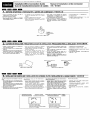
Thank you for purchasing the Clarion Product
* Please read this owner's manual in its entirety before operating this equipment
* After reading this manual, be sure to keep it in a handy place (e g , glove compartment)
* Check the contents of the enclosed warranty card and keep it carefully with this manual
* This manual includes the operating procedures of the CD changer, MD changer and TV connected
via the CeNET cable The CD changer, MD changer and TV tuner have their own manuals, but no
explanations for operating them are described
Contents
1
2
FEATURES
PRECAUTIONS
Handling Compact Discs
Handling Cassette tape
3 CONTROLS
4 NOMENCLATURE
Names of Buttons
Display Items
5 REMOTE CONTROL
Inserting the Batteries
Functions of Remote Control Unit Buttons
6 OPERATIONS
Basic Operations
Radio Operations
CD Operations
Tape Operations
Other Handy Functions
7 OPERATIONS OF ACCESSORIES
CD Changer Operations
M 0 Changer Operations
TV Operations
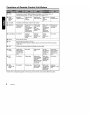
8 TROUBLESHOOTING
9 ERROR DISPLAYS
10 SPECIFICATIONS
•
•
•
•
•
•
•
•
•
•
•
•
•
•
2
8-Times Oversampling Digital Filter and Dual 1-Bit OfA Converters
Zero-Bit Detector™ Mute Circuit
Full Logec Tape Transport with True Function / Auto Reverse with Dual Azimuth Adjust
Dolby® B Noise Reduction
MfiCiI-TUNE@ FM Reception System
Controller for Optional TV Tuner Modules
Capability to Read CD TEXT Data from Clarion Compatible CD Changer
Z-Enhancer with 3 Adjustment Modes
Repeat / Random Play / Intro Music Scan
CeNET with Balanced Audio Line Transmission and Dynamic Noise Canceling
Multi-color FL Display
Bass Control Center Frequency 30Hz f Boost Level ±13dB
4-Channel RCA Line Level Output with Fader Control
180W(45Wx4) Maximum Power Output
ADX5655z
2
3
4
4
5
6
6
6
7
7
8
9
9
11
13
14
16
18
18
20
21
23
24
25
When the insIde of the car IS very cold and
the player IS used soon after switching on the
heater, mOisture may form on the disc or the
optical parts of the player and proper playback may not be possible. If mOisture forms
on the disc, wipe it off with a soft cloth. If mOIsture forms on the optical parts of the player,
do not use the player for about one hour. The
condensation will disappear naturally allowIng normal operation.
This equipment has been tested and found to
comply with the limits for a Class B digital deVice, pursuant to Part 15 of the FCC Rules.
These limits are designed to provide reasonable
protection against harmful Interference In a resIdential Installation.
This equipment generates, uses, and can radiate radio frequency energy and, if not Installed
and used In accordance with the Instructions,
may cause harmful Interference to radio communications. However, there IS no guarantee that
Interference will not occur In a particular Installation.
If this equipment does cause harmful interference to radio or televIsIon reception, which can
be determined by turning the equipment off and
on, the user IS encouraged to consult the dealer
or an experienced radio/TV technician for help.
2. Driving on extremely bumpy roads which
cause severe vibration may cause the sound
to skip.
3. This unit uses a precIsion mechanism. Even
In the event that trouble arises, never open
the case, disassemble the unit, or lubricate
the rotating parts.
USE OF CONTROLS, ADJUSTMENTS, OR
PERFORMANCE OF PROCEDURES OTHER
THAN THOSE SPECIFIED HEREIN, MAY RESULT IN HAZARDOUS RADIATION EXPOSURE.
THE COMPACT DISC PLAYER SHOULD NOT
BE ADJUSTED OR REPAIRED BY ANYONE
EXCEPT PROPERLY QUALIFIED SERVICE
PERSONNEL.
CHANGES OR MODIFICATIONS NOT EXPRESSLY APPROVED BY THE MANUFACTURER FOR COMPLIANCE COULD VOID
THE USER'S AUTHORITY TO OPERATETHE
EQUIPMENT.
CHANGES OR MODIFICATIONS TO THIS
PRODUCT NOT APPROVED BY THE MANUFACTURER WILL VOID THE WARRANTY
AND WILL VIOLATE FCC APPROVAL.
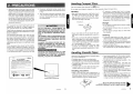
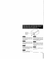
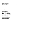
clanon
MODEL
12V 8 GROUND
AM 530-171 OkHz/FM 87.9-107.9MHz
This device complies with Part 15 of the FCC Rules. Operation IS subject to
(1) This device may not cause harmful
the following two conditions
Interference, and (2) This device must accept any Interference received,
Including Interference that may cause undesired operation.
This Production complies DHHS Rules 21 CFR subchapter J applicable at
date of manufacture.
CLARION CO,LTD.
50 KAMITODA, TODA-SHI, SAITAMA-KEN, JAPAN.
MANUFACTURED
Dolby nOise reductIOn manufactured under license from Dolby Laboratones
Licensmg Corporation.
'DOLBY" and the double-D symbol are trademarks of Dolby Laboratones
licensing Corporation.
C
SERIAL No
PE..
051 722 877
o
286-' Clarion CO.L1d
MADE IN,--
Bottom View of Source Unit
ADX5655z
3
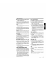
Handling Compact Discs
Use only compact discs beanng the [Q]O~~ mark.
DIGITAL AUDIO
Do not play heart-shaped, octagonal, or other specially shaped compact discs.
Handling
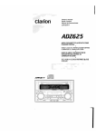
• New discs may have some roughness around
the edges. If such discs are used, the player
mdy not work or the sound may skip. Use a
bali-point pen or the like to remove any roughness from the edge of the disc.
Bali-point pen
~~"
'
'~.
~~7
~'
-----~,~X
Roughness
/:
• Never stick labels on the SUi lace of the compact disc or mark the surface with a pencil or
pen.
• Never playa compact disc with any cellophane
tape or other glue on it or with peeling off marks.
If you try to play such a compact disc, you may
not be able to get it back out of the CD player
or it may damage the CD player.
• Do not use compact discs that have large
scratches, are misshapen, cracked, etc. Use
of such discs may cause mlsoperation or damage.
• To remove a compact disc from its storage
case, press down on the center of the case and
lift the disc out, holding it carefully by the edges.
• Do not use commercIally available CD protection sheets or discs equipped with stabilizers,
etc. These may damage the disc or cause
breakdown of the Internal mechanism.
Storage
• Do not expose compact discs to direct sunlight
or any heat source.
• Do not expose compact discs to excess humidity or dust.
• Do not expose compact discs to direct heat
from heaters.
Cleaning
• To remove fingermarks and dust, use a soft
cloth and wipe In a straight line from the center
of the compact disc to the Circumference.
• Do not use any solvents, such as commercially
available cleaners, anti-static spray or thinner
to clean compact discs.
• After uSing speCial compact disc cleaner, let
the compact disc dry off well before playing it.
Handling Cassette Tapes
USing any of the follOWing types of cassette tapes
can cause malfunctions.
• Cassette tapes with low recording levels
• Cassette tapes In which the unrecorded section between songs IS shorter than 4 seconds
• Cassette tapes with nOise or the like recorded
between songs
• Cassette tapes on which there are long unrecorded sections In the mIddle of a song
Handling precautions
• Slack In the tape can cause malfunctions. In
particular for prerecorded cassette tapes and
gO-minute tapes, take up any slack In the tape
before Inserting it Into the cassette player.
• AVOid uSing cassettes of 120 minutes or longer.
(Such cassettes have extremely thin tape, so
the tape can become stretched or cut.)
• PerIodically playa cleaning cassette In the
player to clean the head.
• Keep magnets, screwdnvers, and other Iron
and steel and magnetic items away from both
cassette tapes and the tape head In the player.
• Do not oil the cassette mechanism.
• Do not use any cassette tapes with peeling labels or deformed cases. Such cassette tapes
can cause breakdowns.
• When not uSing the player, always take the cassette out of the mechanism. ExpOSing a cassette to direct sunlight, extreme temperatures,
or high humidity can damage the cassette.
ADX5655z
4
Source unit /~•.t4DifijreJl
.t-"'i;.t.f,~~·h
/
Unidad fuente/:±tIL
r-:::::::::===============212========~=====================
(
2
HIGHPOWER45Wx4
TUNER/COrv 'ACT DISC/CASSETTE PLAYER WITH SPECTRUM ANALYZER
ADX5655z
Clarion
FULL LOGIC CASSETTE SYSTEM
1
Display / Affictuwur / Visualizador /
JJE 7F riff
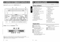
Note: Be sure to unfold thIs page and refer to the front diagrams as you read each chapter.
Rert)arque:Veuf!!ez depfier cette page ot \IOUS reterer aux schernas quand vous fisez C!7t~que chapitre.
Nota: Cuando lea los capftulos, despliegue esta pagma y consulte los diagramas.
I'E/~
5
IF 4<
ADX5655z
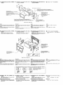
Note:
• Be sure to read thIs chapter referring to the front diagrams of chapter "3. CONTROLS" on page 5 (unfold).
Names of Buttons
w Preset buttons (1 to 6)
[IT] BAND (band) button
Direct buttons (1 to 6) (7 to 12)
TOP button
~ Z-EHCR (z-enhancer) button
[1] DISP (display) button
GJ
PROG (programe) button
[j1] ENT (enter) button
SPE-ANA (spectrum analyzer) button
[ID SCN (scan) button
Play/pause button
~ TITLE button
PSIAS (preset scan/auto store) button
[§] RPT (repeat) button
BLS (blank skip) button
[l] POWER button
FUNC (function) button
[ID ROM (random) button
B NR (Dolby NR) button
[ID ISR (instant station recall) button
[1Q] MUTE button
ADJ (adjust) button
[H] TAPE EJECT button
[j]] Left button
~ Right button
[11] Up button
[lID Down button
[ID A-M (audio mode) button
LOUD (loudness) button
~ CD EJECT button
~ CD Insertion slot
~ Cassette tape Insertion slot
Display Items
D
fJ
D
RPT (repeat) Indication
Operation status Indication
play time, clock, T-scan,
D-scan etc. are displayed.
Z-EHCR (z-enhancer) Indication
m MANU (manual) Indication
m ST (stereo) Indication
D
Preset channel Indication (1 to 6)
Disc number Indication (1 to 12)
* The disc numbers corresponding to the discs
In the CD or MD changer light.
6
* The names of modes being selected, etc. are
ROM (random) Indication
* The frequency,
D
m Function mode Indication
ADX5655z
displayed.
m B NR (Dolby NR) Indication
1m
BLS (blank skip) Indication
m LOUD (loudness) Indication
)
IISHPI1WER45Wx4
TUI'ER/COMPACT OtSC/CASSETTE PLAYER WITH SPECTRLH ANALYZER
~5655z
~\\\\\\~;iiH:a!liiillln
c
rIon
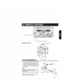
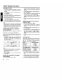
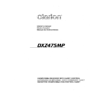
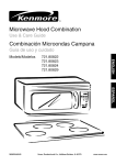
Receiver for remote control unit
Remote control unit
"filii-TUNE
---+-+----1c+-+------f-6>-1
~erating
range: 30° in all directions
c. . -
~
Signal transmitter
.~
~
25
.~
~
~
Inserting the Batteries
1 Turn the remote control unit over, then slide
the rear cover in the direction of the arrow
2 Insert the AA (UM-3/1 5V) batteries that came
with the remote control unit facing in the directions shown in the figure, then close the
rear cover
Notes:
Using batteries improperly can cause them to explode Take note of the following points:
• When replacing batteries, replace both batteries
with new ones
• Do not short-circuit, disassemble or heat batteries
• Do not dispose of batteries into fire or water
• Dispose of spent batteries properly.
AA (UM-3/1 5V)
Batteries
Rear cover
Rear side
j
O~
\
ADX5655z
7
Functions of Remote Control Unit Buttons
~ FUNC
Turns power on and off When pressed and held for 1 second: Turns power off
Switches among radio, CD, Tape, CD changer, MD changer and TV
~ BAND
DISC UP
PROG
TOP
Switches
reception band
~ VOLUME
Increases and decreases volume (in all modes)
~ SEARCH
Moves preset
channels up
and down
Moves tracks up
and down
When pressed
and held for 1
second:
Fast-forward/
fast-backward
Fast-forward
and rewinds
tape
APC fastforward and
rewind
Moves tracks up Moves preset
channels up
and down
and down
When pressed
and held for 1
second:
Fast-forward/
fast-backward
[gz] PLAY/PAUSE
No function
Switches
between
playback and
pause
Switches
between
playback and
pause
Switches
between
playback and
pause
~MUTE
Turns mute on and off
~ ISR
Recalls ISR radio station in memory
Press and hold for 2 seconds or longer: Stores current station into ISR memory (radio
mode only)
~ DISP
Switches among main display, sub display and clock display
~ SCN
PS/AS
Preset scan
When pressed
and held for 2
seconds: Auto
store
Scan play
Fast-forward
scan
Scan play
When pressed
and held for 1
seconds: Disc
scan play
Preset scan
When pressed
and held for 2
seconds: Auto
store
~ RPT
BLS
No function
Repeat play
Repeat play
When pressed
and held for 1
second:
Blank tape skip
function turns
on and off
Repeat play
When pressed
and held for 1
seconds: Disc
repeat play
No function
~ RDM
DOLBY NR
MONI
No function
Random play
Select Dolby
Noise Reduction mode
Random play
When pressed
and held for 1
seconds: Disc
random play
Switches
between TV and
Plays the first
track
Top play
Switches the
side of the tape
Moves the next
disc in
increasing
order
Switches
reception band
No function
VTR
* Some of the corresponding buttons on the source unit and remote control unit have different functions
8
AOX5655z
Basic Operations
Note: Be sure to read this chapter referring to the front diagrams of
chapter "3. CONTROLS" on page 5 (unfold).
Be sure to lower the volume before switching
off the unit power or the ignition key The unit
remembers its last volume setting If you
switch the power off with the volume up, when
you switch the power back on, the sudden
loud volume may hurt your hearing and damage the unit
The clock is displayed when the ignition key
is turned to the ACC (accessory) or IGN (ignition-on) position even when the unit power
is off In some cars, the clock may momentarily disappear when the ignition key is
turned to the START position The clock will
reappear after the engine has started and the
ignition key is released to the IGN (ignitionon) position
Radio mode ~ CD mode ~ Tape mode
CD changer mode ~ MD changer mode
TV mode ~ Radio mode
~
~
* External equipment not connected with CeNET
is not displayed
Adjusting the volume
Press Up button [II] or Down button 11]] increases
or decreases the volume
* The volume level is from 0 (minimum) to 33 (maximum)
Switching the display
Press DISP button []] to select the desired display
Each time you press DISP button []], the display
switches in the following order
Main display
Turning on/off the power
Notes:
• Be careful about using this unit for a long time without running the engine If you drain the car's battery too far, you may not be able to start the engine and this can reduce the service life of the
battery.
• System check
This unit checks what external equipment is connected to the CeNET The first time the ACC/lgnition is turned on (initialization), "SYSTEM" and
"Push PWR" alternately blink in the display. Press
POWER button [j] to start the system check When
complete, press POWER button [j] again to activate the unit then the unit appears CHECKING
COMPLETE
1 Press POWER button [1]
2 The illumination and display on the unit light
up The unit automatically remembers its last
operation mode and will automatically switch
to display that mode
3 Press and hold POWER button [1] for 1 second or longer to turn off the power for the unit
Sub (title) display
Clock display
~
Main display
Selecting a mode
1 Press FUNC button [1] to change the mode
of operation
2 Each time you press FUNC button [1], the
mode of operation changes in the following
order
ADX5655z
9
Basic Operations
* Once selected, the preferred display becomes
the display default When a function adjustment
such as volume is made, the screen will
momentarily switch to that function's display,
then revert back to the preferred display several seconds after the adjustment
* When you have entered a title in a CD, it appears in the sub display If you have not entered a title, "NO-TTL" appears in the title display instead For information on how to enter a
title, refer to the subsection "Entering titles"
in the "Other Handy Functions"
* You can adjust the way of scrolling a title For
the details on it, refer to the subsection
"Adjusting the way of scrolling" in the "Other
Handy Functions"
Setting the Z-enhancer
This unit comes with 3 types of sound tone effects
stored in memory Select the one you prefer
* The factory default setting is "OFF"
Each time you press Z-EHCR button [gJ, the tone
effect changes in the following order
"Z-EHCR 1" ~ "Z-EHCR 2" ~ "Z-EHCR 3" ~
"OFF" ~ "Z-EHCR 1"
• Z-EHCR 1
Adjusting the treble
1 Press A-M button ~ and select "TREB"
2 Press Up button IITI to emphasize the treble,
or press Down button I1ID to attenuate the
treble
* The factory default setting is "0" (Adjustment
range: -6 to +6)
3 When the adjustment is complete, press A-M
button ~ several times until the function mode
is reached
Adjusting the balance
1 Press A-M button ~ and select "BAL"
2 Press Up button IITI to emphasize the sound
from the right speaker, or press Down button
I1ID to emphasizes the sound from the left
speaker
* The factory default setting is "0" (Adjustment
range: L13 to R13)
3 When the adjustment is complete, press A-M
button ~ several times until the function mode
is reached
Adjusting the fader
bass emphasized
• Z-EHCR 2 : treble emphasized
1 Press A-M button ~ and select "FAD"
• Z-EHCR 3 : bass and treble emphasized
2 Press Up button IITI to emphasize the sound
from the front speakers, or press Down button I1!l to emphasize the sound from the rear
speakers
* The factory default setting is "0" (Adjustment
range: F12 to R12)
3 When the adjustment is complete, press A-M
button ~ several times until the function mode
is reached
• OFF
no sound effect
Adjusting the tone
Press A-M button ~ and select the item to adjust Each time you press A-M button ~, the item
changes in the following order
• When the Z-enhancer is off
"BASS" ~ "TREB"
Function mode
~
"BAL"
~
"FAD"
~
Adjusting the Z-enhancer
• When Z-enhancer 1, 2 or 3 is set
"Z-EHCR"
mode
~
"BAL"
~
"FAD"
~
Function
Adjusting the bass
1 Press A-M button ~ and select "BASS"
2 Press Up button IITI to emphasize the bass,
or press Down button I1ID to attenuate the bass
* The factory default setting is "0" (Adjustment
range: -6 to +6)
3 When the adjustment is complete, press A-M
button ~ several times until the function mode
is reached
10
ADX5655z
1 Press Z-EHCR button [gJ and select the Zenhancer mode (1 to 3) to adjust
2 Press A-M button ~ and select "Z-EHCR"
3 Press Up button IITI or press Down button I1!l
to adjusts Z-enhancer
* When Z-enhancer 1 is selected, you can adjust
the bass in the range of ±2
* When Z-enhancer 2 is selected, you can adjust
the treble in the range of ±2
* When Z-enhancer 3 is selected, you can adjust
the bass and treble in the range of ±2
4 When the adjustment is complete, press A-M
button ~ several times until the function mode
is reached
Basic Operations
Radio Operations
Turning on/off the loudness
FM reception
The loudness effect emphasizes the bass and
treble to create a natural sound tone When you
are listening to music at a low volume, it is recommended to use the loudness effect
For
1 Press and hold LOUD button !lID for 1 second
or longer to turn on the loudness effect When
the loudness effect is turned on, "LOUD" lights
in the display
2 Press and hold LOUD button !lID for 1 second
or longer to turn off the loudness effect
"LOUD" goes off in the display
enhanced
FM performance the
MfiGI-TU"E@ tuner includes signal actuated
stereo control and Multipath noise reduction circuits
Changing the reception area
This unit is initially set to USA frequency intervals
of 10kHz for AM and 200kHz for FM When using it
outside the USA, the frequency reception range
can be switched to the intervals below
• Setti n9 the reception area
1 Press FUNC button [l] and select the radio
mode (FM or AM)
2 While pressing DISP button ~, each time you
press and hold the number "6" of the Preset
buttons [I] for 2 seconds or longer, the reception area switches from inside the USA to outside the USA or from outside the USA to inside the USA
* Any station preset memories are lost when the
reception area is changed
Listening to the radio
1 Press FU NC button [l] and select the radio
mode
2 Press BAND button rTIJ and select the radio
band Each time the button is pressed, the
radio reception band changes in the following
order
FM1
~
FM2
~
FM3
~
AM
~
FM1
3 Press Right button IN] or Left button [1ID to tune
in the desired station
Tuning
There are 3 types of tuning mode available, seek
tuning, manual tuning and preset tuning
Seek tuning
1 Press BAND button
band (FM or AM)
rTIJ and select the desired
* If "MANU" is
lit in the display, press and hold
BAND button [jJ for 1 second or longer "MANU"
in the display goes off and seek tuning is now
available
2 Press Right button IN] or Left button [1ID to automatically seek to the next station
When Right button IN] is pressed, the station
is sought in the direction of higher frequencies,
if Left button ~ is pressed, the station is
sought in the direction of lower frequencies
ADX5655z
11
Radio Operations
Manual tuning
Recalling a preset station
There are 2 ways available Quick tuning and step
tuning
When you are in the step tuning mode, the
frequency changes one step at a time In quick
tuning mode, you can quickly tune the desired
frequency
1 Press BAND button [D] and select the desired
band (FM or AM)
Pressing the corresponding preset button recalls
the stored radio frequency automatically
1 Press BAND button [D] and select the desired
band (FM1, FM2, FM3 or AM)
2 Press the corresponding Preset button III to
recall the stored station
* Press and hold one of the Preset buttons [j]
* If "MANU"
is not lit in the display, press and
hold BAND button [j] for 1 second or longer
"MANU" lights in the display and manual tuning
is now available
2 Tune into a station
e Quick tuning:
Press and hold Right button I1&l or Left button
[li] for 1 second or longer to manually tune to
the desired frequency
e Step tuning:
Press Right button I1&l or Left button [li] to
manually tune one step at a time to the desired frequency
Storing a preset station
A total of 24 preset positions (6-FM1 , 6-FM2, 6FM3, 6-AM) exists to store individual radio
stations in memory
Manual memory
1 Select the desired station with seek tuning,
manual tuning or preset tuning
2 Press and hold one of Preset buttons III for 2
seconds or longer to store the current station
into preset memory
Auto store
Auto store selects up to 6 stations and
automatically stores them into preset memory If
auto store cannot tune in all six stations, then it
stores the strongest stations into memory and
the other presets untouched
1 Press BAND button [D] and select the desired
band (FM or AM)
2 Press and hold AS button [ID for 2 seconds or
longer The stations with good reception are
stored automatically to the preset buttons
12
ADX5655z
for 2 seconds or longer to store that station into
preset memory
Preset scan
Preset scan receives the stations stored in preset
memory in order This function is useful when
searching for a desired station in memory
1 Press PS button [ID
2 When a desired station is tuned in, press PS
button [ID again to continue receiving that station
Note:
• Be careful not to press and hold PS button ill for
2 seconds or longer, otherwise the auto store function engages and the unit starts storing stations
Instant station recall (ISR)
Instant station recall is a special radio preset that
instantly accesses a favorite radio station at a
touch of a button The ISR function even operates
with the unit in other modes
elSR memory
1 Select the station that you wish to store in ISR
memory
2 Press and hold ISR button [ID for 2 seconds
or longer
e Recalling a station with ISR
In any mode, press ISR button [ID to turn on the
radio function and tune the selected radio station "ISR" appears in the display Press ISR button [ID again to return to the previous mode
CD Operations
Loading a CD
Selecting a track
Insert a CD into the center of the insertion slot
with the label side facing up The CD plays
automatically after loading
Notes:
• Track-up
1 Press Right button INl to move ahead to the
beginning of the next track
2 Each time you press Right button 1Nl, the track
advances ahead to the beginning of the next
track
• Never insert foreign objects into the CD insertion
slot
• When a CD is loaded in the unit, CD IN indication
lJJ lights in the display. Never try to insert another
CD in this case
[ill
• Discs not bearing the o~JL~l~ mark and CD-ROMs
cannot be played by this unit
• Some CDs recorded in CD-R mode may not be
usable
• Even when recorded in CD-RW mode, some CDs
not be usable
• Track-down
1 Press Left button IIID to move back to the beginning of the current track
2 Press Left button IIID twice to move to the beginning of the previous track
Listening to a CD already inserted
• Fast-forward
Press and hold Right button
longer
COMPACT
Press FUNC button [I] to select the CD mode
Play starts automatically If no CD is loaded in
the unit, "NO DISC" appears in the display
Pausing play
1 Press Play/pause button ~ to pause play
"PAUSE" appears in the display
Fast-forward/fast-backward
INl for
1 second or
• Fast-backward
Press and hold Left button IIID for 1 second or
longer
Top function
2 To resume CD play, press Play/pause button
~ again
The top function resets the CD player to the first
track of the disc Press TOP button IDJ to play the
first track (track No 1) on the disc
Displaying CD titles
Scan play
This unit can display title data for user titles input
with this unit
The scan play locates and plays the first 10
seconds of each track on a disc automatically This
function continues on the disc until it is canceled
* The scan play is useful when you want to select a
desired track
1 Press SCN button []] to start track scanning
"T-SCAN" lights in the display
Press DISP button [1J to display the title
Notes:
• Titles of CD-text CDs cannot be displayed with this
unit
• If the CD playing is a CD-text CD or no user title
has been input, "NO- TTL" appears in the display.
Ejecting a CD
2 To cancel the scan play, press SCN button []]
again "T-SCAN" goes off from the display and
the current track continues to play
Press CD EJECT button ~ to eject the CD Take
it out from the ejected position
* If a 5" CD (12 cm) is left in the ejected position for
15 seconds, the CD is automatically reloaded (Auto
reload)
* 3" CDs (8 cm) are not auto reloaded Be sure to
remove it when ejected
Notes:
• If you force a CD into before auto reloading,
this can damage the CD
* The radio mode is selected automatically 4 seconds
after CD EJECT button !Iff} is pressed
ADX5655z
13
CD Operations
Tape Operations
Repeat play
Loading a tape
The repeat play continuously plays the current
track This function continues automatically until
it is canceled
1 Press RPT button [ID "T-REPEAT" lights in
the display and the current track is repeated
2 To cancel the repeat play, press RPT button
[ID again "T-REPEAT" goes off from the display and normal play resumes
Load a tape into the cassette tape insertion slot
"LOADING" appears in the display and starts
playing
Random play
The random play selects and plays individual tracks
on a disc in no particular order This function
continues automatically until it is canceled
1 Press RDM button [[] "T-RANDOM" lights in
the display, an individual track is selected randomly and play begins
2 To cancel the random play, press RDM button [[] again "T-RANDOM" goes off from the
display and normal play resumes
* When
a metal or chrome bias (70J..l sec) tape is
inserted, the metal bias setting is selected automatically
* The cassette tape slot door shuts automatically
after inserting or ejecting a tape ("Auto shut door
function") It protects the tape mechanism from
any dust
Notes:
• Do not put your hands, fingers or foreign objects
into the cassette tape insertion slot
• When a cassette tape is loaded in the insertion
slot, "TAPE IN" lights in the display. Never try to
insert another tape forcibly.
Listening to a tape already inserted
Press FUNC button [I] to select the tape mode
Play starts automatically If no tape is loaded in
the unit, "NO CASS" appears in the display
Pausing play
1 Press Play/pause button [jl] to pause play
"PAUSE" appears in the display
2 To resume tape play, press Play/pause button ~ again
Ejecting a tape
Press TAPE EJECT button [H] to eject a tape Take
it out from the ejected position
* The
radio mode is selected automatically 4 seconds after TAPE EJECT button [H] is pressed
Switching to the other side of the tape
Press PROG button [1] to change tape direction
and playback
* The tape mechanism automatically reverses direction and engage playback at the end of the tape
(auto reverse)
Fast-forward/fast-backward
• Fast-forward
Press Right button ~
• Fast-backward
Press Left button I1ID
• Canceling FF/REW
Press Play/pause button ~
14
ADX5655z
Tape Operations
• Listening to another source while using FF
or REW ("monitor mode")
To listen to the CD, CD/MD changer or AM/FM
tuner while the mechanism searches, press
FUNC button [I] to select the desired mode The
mechanism will stop automatically when the end
of the tape is reached
Note
• Use FUNC button [l] and select the tape function
to resume tape playback
APe (Auto Program Control) function
The APC function allows the tape to skip forward
to the beginning of the next track or rewind to the
start of the current track
• Skipping forward to the next track ("APCFF")
During tape playback, press Right button [j&] twice
to fast-forward to the next track The next track
stars playing
• Skipping backward to the current track
("APC-REW")
During tape playback, press Left button [1ID twice
to rewind to the start of the current track The
current track plays from the beginning
• Canceling FF/REW APC to resume playback
Press Play/pause button [jl]
• Listening to another source while using
APC ("monitor mode")
To listen to the CD, CD/MD changer or AM/FM
tuner while the mechanism searches, press
FUNC button [I] to select the desired mode The
mechanism will stop automatically when it finds
the next track (in FF APC) or the start of the current track (in REW APC)
Note:
• Use FUNC button [l] and select the tape function
to resume tape playback
Dolby noise reduction system
The Dolby noise reduction system increases the
volume level of high frequency sounds during
recording and sets it back to their original level
during play This system reduces hissing noise
which is typical of cassette tapes
* Dolby noise reduction manufactured under license
from Dolby Laboratories Licensing Corporation
Dolby and the double-D symbol are trademarks of
Dolby Laboratories Licensing Corporation
Intro tape scan play
The intro tape scan allows the first 10 seconds of
all the tracks on the tape to be played This function continues on the tape until it is canceled
1 Press SCN button [[J to start Intro tape scan
"SCAN" lights in the display
2 To cancel the intro tape scan, press SCN button [[J again "SCAN" goes off from the display and the current track continues to play
* When
the end of the tape is reached during
the intro tape scan, the tape mechanism automatically reverses direction and continues the
intro tape scan
* If you select another mode during the intro tape
scan, the mechanism automatically makes the
intro tape scan stop when it finds the next track
(APC function)
Tape repeat play
The tape repeat continuously plays the current
track This function continues automatically until
it is canceled
1 Press RPT button [ID "REPEAT" lights in the
display and the current track is repeated
2 To cancel the repeat play, press RPT button
[ID again "REPEAT" goes off from the display
and normal play resumes
Blank tape skip
The blank tape skip allows you to skip blank sections of tape that are over 12 seconds long
1 Press and hold RPT button [ID for 1 second
or longer "BLS" lights in the display and the
mechanism fastforward to the next track selection
2 To cancel the blank tape skip, press and hold
RPT button [ID again "BLS" goes off and normal play resumes
Notes:
The APC, intra tape scan, tape repeat and blank
skip may not work properly with tapes of the following qualities:
• Tapes on which the recording level is too low
• Tapes on which there is much noise between selections
• Tapes on which there are long pauses in the middle
of selections
• Tapes on which there are less than 4 seconds of
blank space between selections
Press B NR button [ID to select Dolby noise reduction "B NR" lights in the display Each time
you press B NR button [ID, the Dolby toggles
between B NR and OFF
ADX5655z
15
Other Handy Functions
Setting the clock
1 Press and hold ADJ button ~ for 1 second or
longer to switch to the adjustment selection
display
2 Press Right button ~ or Left button l1ID to select "CLOCK"
3 Press ENT button [g]
4 Press Right button ~ or Left button l1ID to select the hour or the minute
5 Press Up button I11l or press Down button 11m
to set the correct time
* The clock is displayed in
12-hour format
6 Press ENT button [g] to store the time into memory
7 Press ADJ button ~ to return to the previous mode
Note:
• You cannot set the clock when it is displayed with
only the ignition on If you drain or remove the car's
battery or take out this unit, the clock is reset While
setting the clock, if another button or operation is
selected, the clock set mode is canceled
Switching the spectrum analyzer
display patterns
You can select one out of 4 patterns or set it to
off
* The factory default setting is "PATTERN 1"
Each time you press SPE-ANA button @J, the
spectrum analyzer display pattern changes in the
following order
PATTERN 1
PATTERN 2
PATTERN 4
PATTERN 5
PATTERN 7
PATTERN 8
OFF ... PATTERN 1
PATTERN 3 ...
PATTERN 6 ...
PATTERN 9 ...
Note:
The spectrum analyzer display is unavailable during these operations below;
• Seek tuning and auto store in radio mode
• Mute or pause
• When "NO DISC" or an error message appears
in the display.
Setting the sensitivity of the spectrum analyzer
* The factory default setting is "MID"
16
AOX5655z
1 Press and hold ADJ button ~ for 1 second or
longer to switch to the adjustment selection
display
2 Press Right button ~ or Left button l1ID to select "ANA SENS"
3 Press Up button I11l or Down button 11m to set
the sensitivity of the spectrum analyzer
You can choose one of "LOW", "MID" or
"HIGH" for the sensitivity of the spectrum analyzer
4 Press ADJ button ~ to return to the previous
mode
Setting the speed of the spectrum
analyzer display
* The factory default setting is "HIGH"
1 Press and hold ADJ button ~ for 1 second or
longer to switch to the adjustment selection
display
2 Press Right button ~ or Left button l1ID to select "ANA SPD"
3 Press Up button I11l or Down button 11m to set
the speed of the spectrum analyzer display
You can choose one of "LOW", "MID" or
"HIGH" for the speed of the spectrum analyzer
display
4 Press ADJ button ~ to return to the previous
mode
Entering titles
Titles up to 10 characters long can be stored in
memory and displayed for radio or TV stations
and CDs The numbers of titles that can be
entered for each mode are as follows
Mode
Radio mode
CD mode
TV mode
Number of titles
30 titles
100 titles
15 titles
CD changer mode
CDC655z connected
CDC655Tz connected
Number of titles
60 titles
100 titles
50 titles
CDC1255z connected
1 Press FU NC button [l] to select the mode you
want to enter a title (radio, CD, CD changer or
TV)
* Titles cannot be entered for MDs with this unit
2 Select and playa CD or a CD in the CD changer,
or tune to an appropriate TV or radio station
3 Press DISP button [1J and display the title
Other Handy Functions
4 Press TITLE button ~ "TITL" appears in the
display and the cursor position flashes
5 Press Right button [lID or Left button [j] to move
the cursor
6 Press DISP button ~ to select a character
Each time you press DISP button~, the character changes in the following order
Capital letters ~ Small letters ~ Numbers/
Symbols ~ Capital letters
7 Press Right button [lID or Left button [j] to select the desired character Pressing Right button [lID moves the cursor to the next character, pressing Left button [j] moves the cursor
to the previous character
8 Repeat steps 5 to 7 to enter up to 10 characters for the title
9 Press and hold ENT button [gJ for 2 seconds
or longer to store the title into memory and
cancel title input mode
Clearing titles
1 Playa CD or a CD in a CD changer, or tune a
radio station or TV station that you want to
clear the title for
2 Press DISP button ~ and display the subtitle
3 Press TITLE button [ID "TITL" appears in the
display and the display switches to the title
input display
4 Press BAND button [TI]
5 Press and hold ENT button [gJ for 2 seconds
or longer to clear the title and cancel the title
input mode
Message display
Clock function
• Time matching
Regarding the "CLOCK INDICATION"
The unit indicates the clock when the car engine
is running (when ACC is ON)
The clock is of 12-hour indication
1 Press the "TITLE" button continuously (for
about 1 second)
~ [ANA_SENS] is indicated
2 Press Left button or Right button and select
"CLOCK__I)"
3 Press the "ENTER" button to indicate the
clock
~ The clock indicates "AM 12 00" and turns
to the "time setting" mode
4 Press Left button or Right button and select
"HOUR" or "MINUTE" may adjust items which
are flashing
5 Press Right button or Left button and match
the time
6 Press the "ENTER" button
7 Press the "TITLE" button
~ The unit returns to the original indication
Triggered audio mute for cellular
telephones
This unit requires special wiring to mute the audio signal automatically when a cellular telephone
rings in the car
* This function is not compatible with all cellular telephones Contact your local authorized Clarion
dealer for information on proper installation and
compatibility
Adjusting the way of title scrolling
When the unit is powered on or off, a message is
displayed The user can turn this message display on or off
There are 3 ways for scrolling a title in the display You can select the way you prefer
* The factory default setting
* The factory default setting is "AUTO"
is "ON"
1 Press and hold ADJ button [ID for 1 second or
longer to switch to the adjustment selection
display
2 Press Right button [lID or Left button [j] to select "MESSAGE"
3 Press Up button ffIl to set the message display to "ON", press Down button !lID to set the
message display to "OFF"
5 Press ADJ button [ID to return to the previous
mode
1 Press and hold ADJ button [ID for 1 second or
longer to switch to the adjustment selection
display
2 Press Right button [lID or Left button [j] to select "SCROLL"
3 Press Up button ffIl or Down button !lID to
change the display Each time Up button ffIl
or Down button !lID is pressed, the display
changes among the 2 display methods available
4 Press ADJ button [ID to return to the previous
mode
ADX5655z
17
CD Changer Operations
CD changer functions
Selecting a CD
When an optional CD changer is connected
through the CeNET cable, this unit controls all
the CD changer functions This unit can control a
total of 2 changers (MD and/or CD)
Each of the Direct button
corresponds to a
disc loaded into the magazine
Press FUNC button [l] and select the CD changer
mode to start play If 2 CD changers are
connected, press FUNC button [l] to select the
CD changer for play
* If "NO
MAGA" appears in the display, insert the
magazine into the CD changer "CHECK" appears
in the display while the player loads (checks) the
magazine
* If "NO DISC" appears in the display, eject the
magazine and insert discs into each slot Then,
reinsert the magazine back into the CD changer
-
rn
• Selecting a disc from 1 to 6
Press the corresponding Direct button
6) to select the desired disc
rn (1 to
• Selecting a disc from 7 to 12 (only when a
12 disc CD changer is used)
Press and hold the corresponding Direct button
(7 to 12) for 1 second or longer to select the
desired disc
rn
* If
a CD is not loaded in a slot of the magazine,
pressing the Direct button [fJ corresponding to its
disc number is invalid
Selecting a track
CD-ROM discs cannot be played in the CD
changer
Pausing play
1 Press Play/pause button [j]] to pause play
"PAUSE" appears in the display
• Track-up
1 Press Right button INl to move ahead to the
beginning of the next track
2 Each time you press Right button 1Nl, the track
advances ahead to the beginning of the next
track
2 To resume play, press Play/pause button [j]]
again
• Track-down
1 Press Left button [§] to move back to the beginning of the current track
Displaying CD titles
2 Press Left button [§] twice to move to the beginning of the previous track
This unit can display title data for CD-text CDs
and user titles input with this unit
Fast-forward/fast-backward
* Title
data for CD-text CDs can be displayed with
this unit only when it is connected to CDC655Tz
• When connected to CDC655z or CDC1255z
Press DISP button []] to display the title
• When connected to CDC655Tz
1 Press DISP button []] to display the title
2 Each time you press and hold DISP button
[]] for 1 second or longer, the title display
changes in the following order
User title (disc) ~ CD-text title (disc)
text title (track) ~ user title (disc)
~
CD-
Notes:
• If the CD playing is not a CD-text CD or no user
title has been input, "USER TTL" appears in the
display.
• If a CD-text CD is not input its disc title or a track
title, "TEXTli1TTL" or "TEXTflTTL" appears in the
display.
18
ADX5655z
• Fast-forward
Press and hold Right button
longer
INl for
1 second or
• Fast-backward
Press and hold Left button [§] for 1 second or
longer
CD Changer Operations
• When playing a disc 1 to 6
Press the Direct button [j] (1 to 6) with the same
number as the CD playing
• When playing a disc 7 to 12 (only when a
12 disc CD changer is used)
Press and hold for 1 second or longer the Direct
button [j] (7 to 12) with the same number as the
CD playing
* If
a CD is not loaded in a slot of the magazine,
pressing the Direct button II] corresponding to its
disc number is invalid
Scan play
The scan play locates and plays the first 10
seconds of each track on a disc automatically
This function continues on the disc until it is
canceled
* The scan play is useful when you want to select a
desired track
1 Press SCN button [ID to start track scanning
"T-SCAN" lights in the display
2 To cancel the scan play, press SCN button [ID
again "T-SCAN" goes off from the display and
the current track continues to play
Disc scan play
The disc scan play locates and plays the first 10
seconds of the first track on each disc in the
currently selected CD changer This function
continues automatically until it is canceled
* The
disc scan play is useful when you want to
select a desired CD
1 Press and hold SCN button [ID for 1 second
or longer DISC indication II and "D-SCAN"
light in the display and the disc scan play
starts
2 To cancel the disc scan play, press SCN button [ID again DISC indication II and "DSCAN" go off from the display and the current track continues to play
Repeat play
The repeat play continuously plays the current
track This function continues automatically until it
is canceled
1 Press RPT button [j] "T-REPEAT" lights in
the display and the current track is repeated
2 To cancel the repeat play, press RPT button
[j] again "T-REPEAT' goes off from the display and normal play resumes
Disc repeat play
After all the tracks on the current disc have been
played, the disc repeat play automatically replays
the current disc over from the first track This
function continues automatically until it is
canceled
1 Press and hold RPT button [[J for 1 second
or longer DISC indication II and "D-REPEAT"
light in the display and the disc repeat play
starts
2 To cancel the disc repeat play, press and hold
RPT button [[J again DISC indication II and
"D-REPEAT" go off from the display and normal play resumes on the current track
Random play
The random play selects and plays individual
tracks on the disc in no particular order This
function continues automatically until it is
canceled
1 Press RDM button I]] "T-RANDOM" lights in
the display and the random play begins
2 To cancel the random play, press RDM button [j] again "T-RANDOM" goes off from the
display and normal play resumes
Disc random play
The disc random play selects and plays individual
tracks or discs automatically in no particular
order This function continues automatically until
it is canceled
1 Press and hold ROM button [j] for 1 second
or longer DISC indication II and
"D-RANDOM" light in the display and the disc
random play starts
2 To cancel the disc random play, press and hold
ROM button [j] again DISC indication II and
"D-RANDOM" go off from the display and normal play resumes from the current track
ADX5655z
19
MD Changer Operations
MD changer functions
When an optional MD changer is connected
through the CeNET cable, this unit controls all
the MD changer functions This unit can control
a total of 2 changers (MD and/or CD)
Press FUNC button [l] and select the MD changer
mode to start play If 2 MD changers are connected, press FUNC button [l] to select the MD
changer for play
* If "NO DISC" appears in the display, load MDs into
the MD changer
Pausing play
1 Press Play/pause button ~ to pause play
"PAUSE" appears in the display
2 To resume play, press Play/pause button ~
again
Switching disc titles and track titles
This unit can display disc titles and track titles
already entered on MDs
* Titles cannot be entered for MDs with this unit
1 Press DISP button I]] to display the title The
disc title or track title is displayed
2 Each time you press and hold DISP button
I]] for 1 second or longer, the display toggles
between the disc title and the track title
Note:
• If an MD is not input its disc title or a track title,
"IJJ TITLE" or 'fj TITLE" appears in the display.
Selecting an MD
Each of the Direct button [I] corresponds to an
MD loaded into the MD changer Press the
corresponding Direct button [I] (1 to 6) to select
the desired disc
* If an MD is not loaded in a slot of the MD changer,
pressing the Direct button [I] corresponding to its
disc number is invalid
Selecting a track
• Track-up
1 Press Right button [1]] to move ahead to the
beginning of the next track
2 Each time you press Right button [1]], the track
advances ahead to the beginning of the next
track
20
ADX5655z
• Track-down
1 Press Left button ffID to move back to the beginning of the current track
2 Press Left button ffID twice to move to the beginning of the previous track
Fast-forward/fast-backward
• Fast-forward
Press and hold Right button [1]] for 1 second or
longer
• Fast-backward
Press and hold Left button ffID for 1 second or
longer
Top function
The top function plays from the first track (track
No 1) of the disc Press the Direct button [I] (1
to 6) with the same number as the MD playing
* If an MD is not loaded in a slot of the MD changer,
pressing the Direct button [I] corresponding to its
disc number is invalid
Scan play
The scan play locates and plays the first 10 seconds of each track on a disc automatically This
function continues on the disc until it is canceled
* The scan play is useful when you want to select a
desired track
1 Press SCN button I]] to start track scanning
"T-SCAN" lights in the display
2 To cancel the scan play, press SCN button I]]
again "T-SCAN" goes off from the display and
the current track continues to play
Disc scan play
The disc scan play locates and plays the first 10
seconds of the first track on each disc in the
currently selected MD changer This function
continues automatically until it is canceled
* The disc scan play is useful when you want to select a desi red MD
1 Press and hold SCN button I]] for 1 second
or longer DISC indication II and "D-SCAN"
light in the display and the disc scan play
starts
2 To cancel the disc scan play, press and hold
SCN button I]] again DISC indication II and
"D-SCAN" go off from the display and the current track continues to play
MD Changer Operations
TV Operations
Repeat play
TV tuner functions
The repeat play continuously plays the current
track This function continues automatically until
it is canceled
1 Press RPT button [[] "T-REPEAT" lights in
the display and the current track is repeated
2 To cancel the repeat play, press RPT button
[[] again "T-REPEAT" goes off from the display and normal play resumes
When an optional TV tuner is connected through
the CeNET cable, this unit controls all TV tuner
functions To watch TV requires a TV tuner and
monitor
Disc repeat play
After all the tracks on the current disc have been
played, the disc repeat play automatically replays
the current disc over from the first track This
function continues automatically until it is
canceled
1 Press and hold RPT button [[] for 1 second
or longer DISC indication II and "D-REPEAT"
light in the display and the disc repeat play
starts
2 To cancel the disc repeat play, press and hold
RPT button [[] again DISC indication II and
"D-REPEAT" go off from the display and normal play resumes on the current track
Random play
The random play selects and plays individual
tracks on the disc in no particular order This
function continues automatically until it is
canceled
1 Press RDM button 00 "T-RANDOM" lights in
the display and the random play begins
2 To cancel the random play, press RDM button 00 again "T-RANDOM" goes off from the
display and normal play resumes
Disc random play
The disc random play selects and plays individual
tracks or discs automatically in no particular
order This function continues automatically until
it is canceled
1 Press and hold RDM button 00 for 1 second
or longer DISC indication II and
"D-RANDOM" light in the display and the disc
random play starts
2 To cancel the disc random play, press and hold
RDM button 00 again DISC indication II and
"D-RANDOM" go off from the display and normal play resumes from the current track
Watching a TV
1 Press FUNC button [l] and select the TV
mode
2 Press BAND button [1] to select the desired
TV band (TV1 or TV2) Each time the button
is pressed, the input selection toggles
between TV1 and TV2
3 Press Right button IN] or Left button l1ID to tune
in the desired TV station
Watching a video
The TV tuner has a VTR input terminal to which
1 external device can be connected Connect a
12V video cassette player (VCP) or video
cassette recorder (VCR) to the TV tuner input
terminal
1 Press RDM button 00 to select VTR
2 To return to the TV broadcast, press RDM
button 00
Tuning
There are 3 types of tuning mode available, seek
tuning, manual tuning and preset tuning
Seek tuning
1 Press BAND button [1] and select the desired
TV band (TV1 or TV2)
* If "MANU" is
lit in the display, press and hold
BAND button ITIJ for 1 second or longer "MANU"
in the display goes off and seek tuning is now
available
2 Press Right button IN] or Left button l1ID to automatically seek to the next station
Press Right button IN] to automatically tune
up the frequency band to the next available
TV station, press Left button l1ID to automatically tune down
ADX5655z
21
TV Operations
Manual tuning
Auto store
There are 2 ways available: Quick tuning and step
tuning
Auto store selects 6 TV stations automatically and
stores each one into a preset memory
When you are in the step tuning mode, the
frequency changes one step at a time In quick
tuning mode, you can quickly tune the desired
frequency
If there are not 6 stations with good reception,
stations previously stored in memory remain and
only the strong stations are stored into memory
1 Press BAND button [j] and select the desired
TV band (TV1 or TV2)
1 Press BAND button [j] and select the desired
band (TV1 or TV2)
* If "MANU" is not lit in the display, press and
hold BAND button [1] for 1 second or longer
"MANU" lights in the display and manual tuning
is now available
2 Tune into a station
• Quick tuning:
Press and hold Right button I1ID or Left button
IIID for 1 second or longer to quickly tune up
and down to a desired station
• Step tuning:
Press Right button I1ID or Left button IIID to
manually tune to a station, one channel at a
time
Recalling a preset station
A total of 12 TV stations can be stored (6-TV1
and 6-TV2) This allows you to select your favorite
TV stations and store them in memory for later
recall
2 Press and hold AS button [ID for 2 seconds or
longer The stations with good reception are
automatically stored to the Preset buttons [I]
Preset scan
Preset scan allows the user to view each preset
position before it automatically advances to the
next preset This function is useful for searching
for a desired TV station in memory
1 Press PS button [ID
2 When a desired station is found, press PS
button [ID again to remain tuned to that station
Note:
for 2 seconds
• Do not press and hold PS button
or longer Doing so will trigger the auto store
function and start storing stations into memory.
m
Setting the receiver for Diversity
tuning
1 Press BAND button [j] and select the desired
TV band (TV1 or TV2)
You can change the reception setting for the TV
antenna connected to the TV tuner
2 To recall a stored TV station, press the desired
Preset button [I] to select that station
* Press and hold one of the Preset buttons [II
* The factory default setting is "ON"
for 2 seconds or longer to store the current station into the preset memory
Manual memory
1 Select the desired station with seek tuning,
manual tuning or preset tuning
2 Press and hold one of the Preset buttons [I]
for 2 seconds or longer to store the current
station to that preset memory
1 Press and hold ADJ button IIID for 1 second or
longer to switch to the adjustment selection
display
2 Press Right button I1ID or Left button IIID to select "TV DIVER"
3 Press Up button [jlJ to set to "ON" or Down
button [jj] to set to "OFF"
ON:
In the "ON" position, the TV tuner emphasizes
the visual signal by choosing the antenna with
the best signal strength This requires more
than one antenna on the vehicle
OFF:
Set the TV Diver adjustment to the "OFF" position when only using one antenna on the
vehicle
4 Press ADJ button
mode
22
ADX5655z
IIID to return to the previous
Power does not
turn on
(No sound is
produced)
Replace with a fuse of the same amperage If the
fuse blows again, consult your store of purchase
Incorrect wiring
No sound output
when operating
the unit with
amplifiers or
power antenna
attached
Power antenna lead is
shorted to ground or
excessive current is required
for remote-on the amplifiers
or power antenna
Nothing happens
when buttons are
pressed
The microprocessor has
malfunctioned due to noise,
etc
Consult your store of purchase
1 Turn the unit off
2 Remove all wires attached to the power antenna
lead Check each wire for a possible short to
ground using an ohm meter
3 Turn the unit back on
4 Reconnect each amplifier remote wire to the
power antenna lead one by one If the amplifiers
turn off before all wires are attached, use an
external relay to provide remote-on voltage
(excessive current required)
Press the reset button with a thin rod
~~jl
-~~
Sound is bad
directly after
power is turned
on
Playback head is dirty
Use a cleaning tape, etc, to clean the head
B NR button [I] is not
pressed
When listening to a tape recorded with Dolby NR,
press B NR button [ID and select B NR
Another CD is already
loaded
Eject the CD before loading the new one
CD is dirty
Clean the CD with a soft cloth
CD is heavily scratched or
warped
Replace with a CD with no scratches or no warped
Water droplets may form on
the internal lens when the
car is parked in a humid
place
Let it dry for about 1 hour with the power on
ADX5655z
23
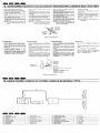
II. ..111111111 111111111..,.,1
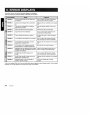
If an error occurs, one of the following displays is displayed
Take the measures described below to eliminate the problem
A CD is caught inside the CD deck and is
not ejected
This is a failure of CD deck's mechanism
and consult your store of purchase
A CD cannot be played due to scratches,
etc
Replace with a non-scratched, non-warped
disc
Tape cannot be played due to defective
tape such as cut tape
Eject the tape then replace it with a new
one
Tape is caught and cannot be played
Remove the caught or wound tape
Tape mode cannot be detected
This is a failure of tape mechanism and
consult your store of purchase
Tape is caught and cannot be ejected
Eliminate the reason for which the tape is
caught
A CD inside the CD changer is not loaded
This is a failure of CD changer's mechanism and consult your store of purchase
A CD inside the CD changer cannot be
played due to scratches, etc
Replace with a non-scratched, non-warped
disc
A CD inside the CD changer cannot be
played because it is loaded upside-down
Eject the disc then reload it properly
Displayed when the temperature in the MD
changer is too high and playback has been
stopped automatically
Lower the surrounding temperature and
wait for a while to cool off MD changer
An MD inside the MD changer is not
loaded
This is a failure of MD changer's mechanism and consult your store of purchase
An MD inside the MD changer cannot be
played due to scratches, etc
Replace with a non-scratched, non-warped
disc
Displayed when a non-recorded MD is
loaded in the MD changer
Load a pre-recorded MD in the MD
changer
If an error display other than the ones described above appears, press the reset button If the problem
persists, turn off the power and consult your store of purchase
24
ADX5655z
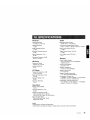
FMTuner
Audio
Frequency Range
87 9 MHz to 1079 MHz
Maximum Power Output
180 W (45 W x 4 ch) (EIAJ)
Usable Sensitivity
11 dBf
Continuous Average Power Output
16 W x 4, into 4 Q, 20 Hz to 20 kHz, 1% THD
50dB Quieting Sensitivity
17 dBf
Alternate Channel Selectivity
75 dB
Stereo Separation (1 kHz)
35 dB
Bass Control Action (30 Hz)
±13 dB
Treble Control Action (10kHz)
±10 dB
Line Output Level (CD 1kHz)
18V
Frequency Response (±3 dB)
30 Hz to 15 kHz
General
AM Tuner
Frequency Range
530 kHz to 1710kHz
Usable Sensitivity
25 f.1V
CD Player
Frequency Response (±1 dB)
10 Hz to 20 kHz
Signal to Noise Ratio (1 kHz)
100 dB
Dynamic Range (1 kHz)
95 dB
Harmonic Distortion
o 01 %
Power Supply Voltage
144 V DC (108 to 156 V allowable),
negative ground
Current Consumption
Less than 15 A
Speaker Impedance
4 Q (4 Q to 8 Q allowable)
Weight / Source unit
5 7 Ib (2 6 kg)
Weight / Remote control unit
1 oz (30 g) (including battery)
Dimensions / Source unit
7" (Width) x 3-15/16" (Height) x 6-1/8" (Depth)
[178 (W) x 100 (H) x 155 (D) mm]
Dimensions / Remote control unit
1-3/4" (Width) x 4-5/16" (Height) x 1-1/8" (Depth)
[44 (W) x 110 (H) x 27 (D) mm]
Tape Deck
Wow & Flutter (WRMS)
o 06 %
Channel Separation (1 kHz)
45 dB
Frequency Response (±3 dB)
120~s (normal) 30 Hz to 18 kHz
70~s (Cr02 FeCr, Metal) 30 Hz to 20 kHz
Signal to Noise Ratio
70~s (Cr02 FeCr, Metal) 58 dB
Dolby B NR 67dB
Notes:
• Specifications comply with EIA Standards
• Specifications and design are subject to change without notice for further improvement
ADX56557
25
Clarion Co., Ltd.
2000/2 (D/ToeC)
All Rights Reserved Copyright © 2000: Clarion Co , Ltd
Printed in China / lrnplirne on Crl!ne / Inpreso en China / $ ~£nBjJ
PE-23228
280-7452-01
Printed in China 1 imprime au Chine Ilmpreso en China 1 tE<pI@,PlilJ 1999 111 (W.C) 284·9114-00
Clarion'
-
Manuel
InstaliationlWire Connection Guide
Gufa de installaci6n/conexi6n de cables
installation
$:~/fi~1~~
--
-1 . BEFORE STARTING IPREPARATIFSI ANTES DE COMENZAR 1*~fif1=±1W
This set is exclusively for use in cars with a
negative ground 12 V power supply
2 Read these instructions carefully
3 Be sure to disconnect the battery " 8 " terminal
before starting This is to prevent short circuits
during installation (Figure 1)
Cet appareil est con9u e;<:c!usivement pour les
voitures dont I'alimentation est de 12 V a masse
negative
2 Veuillez lire altehtivemehl ces instl uctions
3 Veillez a debrancher la borne negative" ''0 " de la
batterie avant d'installer I'appareil afin d'eviter tout
courl-circuit (Figure 1)
:$:.tJ1fx.ffl'ftt!IUl!£t 1;] 12 V, fft :f&~Ji!!fJ"J$I;I;t
iffff~l-m Wi:$:iStllJl ~o
3 7filMltr-litr, WilifllUBli9T7f§ftt!1tf!.fJ"J "8" tIt
1;]TllJjl!:tEg;:~'t'J,t~mJl!}o (001)
Esta unidad ha sido disenada para utilizarse
exclusivamente en autom6viles con fuente de
alimentaci6n de 12 V, Y negativo amasa
2 Lea cuidadosamente estas instrucciones
3 Antes de comenzar la instalaci6n, cerci6rese de
desconectar el terminal" 8 " de la bate ria Esto es
para evitar cortocircuitos durante la instalaci6n
(Figura 1)
1
2
i!~
Car battery
BaUerie de voiture
Saleria del aUlom6vil
;'t$Vil!.i1!!
Figure 1 / Figure 1 / Figura 1 / iii 1
----
-2. CAUTIONS ON INSTALLATION IPRECAUTIONSAUSUJETDE
Prepare all articles necessary for installing the
source unit before starting
2 Install the unit within 30° of the horizontal plane
(Figure 2)
3 If you have to do any work on the car body, such as
drilling holes, consult your car dealer beforehand
4 Use the enclosed screws for installation Using
other screws can cause damage (Figure 3)
NI PRECAUCIONES PARA LA INSTALACION I ~~~~m.Jffj
Avant de commencer I'installation de I'appareil
pilote, preparez toutes les pieces necessaires
2 Installez: I'appareil a I'horizontale, a un angle maxi·
mum de 30" (Figure 2)
3 Si vous devez effectuer des travaux sur la
carresserie, par exemple percer des treus,
consultez votre concessionnaire auto auparavant
4 Utilisez les vis fournies pour I'installation
Lutilisation de toute autre vis peut causer des
dommages (Figure 3)
.-
Max 5/16"(8 mm)
~ - - - Max 5/16"(8 mm)
Max. 5/16"(8 mm)
:Ill);, 5/16" 8 mm)
-3. INSTALLING THE SOURCE UNIT I INSTALLATION
0
f9! ffl;lt 'B fJ"J ~~tiiJ ~~
Damage
: Endommage
I
Daiiado
~_~JJ-
I.'APPAREILPIEOTEIINSTALACION DE LA UNlOAD FUENTE/:Em~~~
Cet appareil est con9u pour etre installe dans Ie
tableau de bord
1 Si vous installez I'appareil pilote dans un vehicule
NISSAN, utiliset les pieces attachees a I'appareil
et suivez les instructions de la figure 4
Si vous installez I'appareil dans un vehicule
TOYOTA (Figure 5), utilisez les pieces attachees au
vehicule et suivez les instructions de la figure 5
2 Raccordez comme indique dans Ie paragraphe 6
3 Montez et fixez l'apparell dans Ie tableau de bord et
posez Ie panneau avant et Ie panneau central
Mounting Screw Holes
Side View of the Source Unit
mi¥J§i\?fifJJ
Figure 3/ Figure 3/ Figura 3/1i13
----
This unit is designed for fixed installation in the dashboard
1 When installing the source unit in NISSAN vehicles,
use the parts attached to the unit and follow the
instructions in Figure 4
When installing the source unit in TOYOTA vehicles
(Figure 5), use the parts attached to the vehicle and
follow the instructions in Figure 5
2 Wire as shown in Section 6
3 Reassemble and secure the unit in the dashboard
and set the face panel and center panel
1'19 Ft$ fJ"J
4. 1C~ Bi iWitffl ~ ffHlHJt fJ"J ~~to
~l9l.ll14tJLo
( 00 3 )
I
I
---""--_
3 j(O*~tE$1*J:*1T~tr-, t~Jw~fLz~~, rNloJf~
.- - --
--
I
I
I
I
Figure 2/ Figure 2/ Figura 2/1i12
(00 2)
2tJ1ftl'mlHc~nX;.!:5Jj(3fITifjj\(; 30 gt~jj'J,
Chassis / Chassis / Chasis / tJL:Ill
Chassis 1 Chassis 1 Chasis ItJUll
-
Max 30°
Max 30"
Max 30°
:Ill*: 30°-'-
1 g;:~litr)l\Z&ifP)f:ft g;:~i:fJLPJf~fJ"Jrtmr\6o
Antes de comenzar la instalaci6n, prepare todos
los elementos necesarios para instalar la unidad
fuente
2 Instale la unidad con un angulo de 30° sobre el
plano horizontal (Figura 2)
3 Si tiene que realizar cualquier trabajo en la
carroceria, como taladrado de orificios, etc,
consulte al proveedor de su autom6vil
4 Utilice los tornillos suministrados para la
instalaci6n La utilizaci6n de otros tornillos pod ria
resultar en danos (Figura 3)
Orifices de montage
Vll~
latqrale del'appareil pilote
Esta unidad ha sido disenada para instalarse fijada al
tablero de instrumentos
Cuando instale la unidad fuente en un autom6vil
NISSAN, utilice las piezas suministradas con fa
unidad, y siga las instrucciones de la Figura 4
Cuando instale la unidad fuente en un autom6vil
TOYOTA (Figura 5), utilice las piezas fijadas al
autom6vil y siga las instrucciones de la Figura 5
2 Conecte los cables como se muestra en la Secci6n 6
3 Ensamble y asegure la unidad al tablero de
instrumentos, y coloque el panel frontal y el panel
central
tE NISSAN ( B F) Ft$J:g;:~Bi, Wif9!ffl i:tJ1Pk:ti'
fJ"J IltHtI':lHIJffi 00 4 Jrr ffi fJ"J tl1 '31
tETOYOTA ($EB) Ft$ (005) J:g;:~Bt, iff9!ffl
i:fJ1Pklll'fJ"Jj!f;HHt-:ilJffiOO 5 PJfffil'l9t1J'3l
2 tp;~ 6 !nJfffi*ft~o
3 :IJw!:b; llH.R ~ 1&J: (j<J i:tJ1:1f f9! ;t 2¥ ~, 1C tit lIif 1&;fU
I*J1&
Orificios para los tomillos de montaje $!ilUUHL---...,
Vista lateral de la unidad fuente
3::*Jta<J1J(IJ:fi\1iI
~@~, ~,
~@ ®
Screw holes for NISSAN vehicle
Orifices pour un vehicule NISSAN
Onficios para lomillos para un autom6vil NISSAN
mer NISSAN ( 13 F) [',$a<JliIlIiHL
:$:tJ1i,9:tt 1) ~ JE tEf.R ~1& J:,
Screw holes for TOYOTA vehicle
Orifices pour un vehicule TOYOTA
Orificios para lomillos para un aUlom6vii TOYOTA
mer TOYOTA
CT·Q] )
~$a<JliIlI!'!.fL
0
0
0
• Installing the Source Unit in a NISSAN
Vehicle
•
Instalaci6n de la unidad fuente en un
autom6vil NISSAN
•
Installation de I'appareil pilote dans
un vehicule NISSAN
Note 2 / Remarque 2/ Nota 2 / i±~ 2
6-Spacer (Provided with the installation kit. sold separately)
6-Entretoises (Fourni avec Ie kit de montage. vendu separement)
6-Separador (Se suministra, con el juego de instalaci6n. vendido aparte)
6 t'Ht OfHI1Ag1i:'iliIl{., !]j t. )
6-Double-sided tape
(Provided with the installation kit. sold separately)
6-Bande a double face adhesive
(Fourni avec Ie kit de montage. vendu separement)
6-Cinta adhesiva por ambas caras
(Se suministra con el juego de instalaci6n, vendido aparte)
6XJ(fHi~*
~I
rJ"
o
0 '&J
~
o
o
0t!.::i<J:;:'
~ ~~
'"
OIt*fI'J1i:'iliIJ'I.. !]jl1i)
/
6-Flat head screw (M5 x 8)
(attached to the source unit)
6-Vis tete plate (M5 x 8)
(sur I'appareil pilote)
; - 6-Tornillos de cabeza plana (M5 x 8)
,~"'~o
n.~.j"@
. '-. .
~
'~
17""-@l
~
Finisher (Provided with the installation kit, sold separately) (Note 1)
Finisseur (Fourni avec Ie kit de montage. vendu separement) (Remargue t)
Placa de adorno (Se suministra con el juego de instalaci6n, vendido aparte) (Nota 1)
[jj]jEW~ OH*A91i:'iIi 1 J'I. ,1}i!i) (lt~l)
a
~
""-- 0
I
~
'-....""CI
/
~....
\
(fija",dO"S, a la unidad fuente)
6 t-'f3l<~ti: (M5 x 8 )
(Hit FHI1 )
....
........~
'~
Mounting bracket (Metal plate)
~ Etriers (plaque metalliquej
Soporte de montaje (Placa metalica)
t!L~ (~Jilita)
Figure 41 Figure 41 Figura 4/004
Yote 1:
::>osition the face panel with its wide edge at the
)ottom Fit the edge into the groove of the source unit
r-Iote2:
::>eel off the exfoliation sheet from the tape and attach
[he spacer to the source unit
•
Installing the Source Unit in a TOYOTA
Vehicle
Remarql1e 1:
Posez Ie panneau avant avecta bord Ie pius large
dirige vers Ie bas Inserez Ie bard dans la rainure de
I'appareil pilote
Remarque2:
Enlevez la feuille de proteGtipn de la bande et collez
I'entretoise sur I'appareil pilote
•
Installation de I'appareil pilote dans
un vehicule TOYOTA
Nota 1:
i'tif 1 :
Coloque el panel frontal con su borde ancho en la
parte inferior Fije el borde en la unidad fuente
:g;:\'l!iVtffL
Nota 2:
Despegue el papel de exfoliaci6n de la cinta y fije el
separador a la unidad fuente
.T• • k~~.,.m~~.:l:fJU§M.
•
Instalaci6n de la unidad fuente en un
autom6vil TOYOTA
•• 1£ TOYOTA ($I':EI)
Instalaci6n de fa unidad utilizando las piezas
fijadas al autom6vil (Los tomillos marcados con
est{m fijados al autom6vil )
)
IInstalier avec les pieces fixees au vehicule (Les
vis indiquees par sont fixees au vehicule )
Install by using parts attached to the vehicle
(Screws marked are attached to the vehicle)
*
1llf,f&rreff~'iX~,
i:tif2 ;
;"i:$..t*~::l:.m
Rm~$kM.~.#~&. (~~*%~~~.~$
~tl*~.
*
*
¥f:l'l;j;QWHrx;\.:l:fnfJl:9tIi%': u ,
8-Hexagon screw (M5 x 8)
(attached to the source unit)
'--
Center Panel (Note 3)
Panneau central (Remargue 3)
Panel central (Nota 3)
9' fHiita (I-un)
Mounting bracket (Metal plate)
Etriers (plaque m6tallique)
Soporte de montaje (Placa metalica)
tit'll!
(~Iillta)
Note 4
Remargue 4
Nota 4
i±~4
Figure 51 Figure 5/ Figura 5/00 5
Note 3:
Some panel openings are too small for the unit
depending on the vehicle type and model In such a
case, trim the upper and lower sides of the panel frame
by about 1/64" to 3/64" (0 5 to 1 5 mm) so the unit can
be inserted smoothly
Note 4:
If a hook on the installation bracket interferes with the
unit, bend and flatten it with a nipper or similar tool
Remarque3:
Nota 3:
i:tif3 :
Selon Ie modele et Ie type de vehicule, les ouvertures
sont parfois trap petites pour I'appareil Dans ce cas.
ajustez les cotes superieur et inferieur du panneau
d'environ 1/64"
3/64" (0.5
1,5 mm) pour que
I'appareil puisse etre insere sans probleme
Algunas aberturas del panel son demasiado pequenas
para la unidad dependiendo del tipo y modelo de
autom6vil En tal caso, recorte las partes superior e
inferior del marco del panel de 1/64" a 3/64" (0,5 a 1,5
mm) a fin de poder insertar facilmente la unidad
.~$.%~~~. _~Illf~~*R~f.:l:m®!~~ ~
jipmlBl'. ~:idm~~IV!J1l;ftl)ff;j;Qt~OHIJl5mm. {t1~.:l:
Remarque4:
Si un crochet du support d'installation gene I'appareil.
rabattez-Ie completement avec une pince ou un outil
similaire
Nota 4:
Si un gancho del soporte de montaje interfiere en la
unidad, d6blelo y aplanelo con unos alicates u otra
herramienta similar
a
a
Typical Mounting Brackets 1 Exemples de fixation de l'IHrier I Soprtes para montaje trpico I
mrimJ@!;fIJa'~ttliA.
i:£ti14
1lD!~Hn!#1l.~ftJfM~~1i:&.
i'lf1tmWT~?R1t!~
L!'!·#ff
'f:;.
~~~m~
Affix the screws to the. marks
Inserez les vis dans les orifices indiques pal •
Fije los tomillos a las marcas •
fM5E •
Example 1:
Exemple 1:
Ejemplo 1:
iJlJ'1'1 :
• Vehicles other than NISSAN and
TOYOTA
111 some cases the center panel may require modification (Trimming, filing, etc)
• Removing the Source Unit
When the soure unit is to be removed, disassemble
it in the reverse of the order in "INSTALLING THE
SOURCE UNIT'
•
Example 2:
Exemple2:
Ejemplo2:
f§tJ'1'2 :
Vehicules d'u;ne autre marque que
NISSAN et TOYOTA
Dans certains cas.lepanneau central devra subir
quelques modifications (Ajustement, limage, etc)
• Retrait de I'appareil pilote
Si vous devez enlever I'appareil pilote, demontez-Ie
en procedanl
I'inverse de "INSTALLATION DE
l.:APPAREIL PILOTE"
a
t*lCl..ffJ~ti:.
Example 3:
Exemple3:
Ejemplo3:
f§tJ1"3 :
•
Autom6viles que no sean NISSAN ni
TOYOTA
En algunos casos, el panel frontal puede requerir
modificaci6n (Recorte, Iimado, etc)
• Desmontaje de la unidad fuente
Cuando desee desmontar la unidad fuente, Mgalo
en sentido inverso al de "INSTALACI6N DE LA
UNIDAD FUENTE"
•
X'fTNISSPN
9~B9n:$
(Sf")
~nOYOTA ($I':EI)
~~'l\\'lBT, <p9I:Illf~1i'ii~1t1:iL (~iL Ji!!fc~)
• m1l*::EfJl.
j)f~±mB>t,
i'lftte "1i:&.:l:m"
~;j>§)jUXff*j{.
Z
• Installing the Source Unit in a NISSAN
Vehicle
II Instalilation de I'appare.il pilote dans
un vehicule NISSAN
•
Instalacion de la unidad fuente en un
automovil NISSAN
Note 2/ Remarque 2/ Nota 2/ iilit 2
6-Spacer (Provided with the installation kit, sold separately)
6-Entretoises (Fourni avec Ie kit de montage, vendu separement)
6-Separador (Se suministra con el juego de instalaci6n, vendido aparte)
6 ilHt (lIfH!J'H'J'!<'i~Tl> ~W)
6-Double-sided tape
(Provided with the installation kit, sold separately)
6-Bande double face adhesive
(Fourni avec Ie kit de montage, vendu separement)
6-Cinta adhesiva por ambas caras
(Se suministra con el juego de instalaci6n, vendido aparte)
a
6)l(ilifID<1ll'
Of-f1ll'ai12'lliIJ'L
0
<,,;
o
o
o
~In
~I
'Ai)
~
rJ"
/
~ l'~,
j
n..@"",,-@~ p~
at.::;<\::<.
. ."""-
~ ~©
~
.~
17""@.....
~
6-Flat head screw (M5 x 8)
(attached to the source unit)
6-Vis tete plate (M5 x 8)
(sur I'appareil pilote)
~ 6-Tomiflos de cabeza plana (M5 x 8)
a
I
~
"",,-""C'
"'-- 0
(liJ.·a
. dO.S. a I.a unidad luente)
6 1''¥*~!f (M5 x 8 )
(1'.!Jl Fl ':tJ' )
~"~
Finisher (Provided with the installation kit, sold separately) (Note 1)
Finisseur (Fourni avec Ie kit de montage, vendu separement) (Remargue 1)
Placa de adorno (Se suministra con el juego de instalaci6n, vendido aparte) (Nota 1)
IIfI '£W'" (lIfH1Hn12'lli 1 fI. 511!f) Ucl:1Ji 1 )
'~
\
Mounting bracket (Metal plate)
~ Etriers (plaque metailique)
Soporte de montaje (Placa metalica)
WW
(~)il!t&)
Figure 4/ Figure 41 Figura 4/004
Note 1:
Remarque 1:
Nota 1:
Position the face panel with its wide edge at the
bottom Fit the edge into the groove of the source unit
Posez Ie panneau avant avec Ie bord Ie plus large
dirige vers Ie bas Inserez Ie bord dans la rainure de
I'appareil pilote
Coloque el panel frontal con su borde ancho en la
parte inferior Fije el borde en la unidad fuente
Remarque2:
Enlevez la feuille de protection de la bande et collez
I'entretoise sur I'appareil pilote
Nota 2:
i:tif2 :
Despegue el papel de exfoliaci6n de la cinta y fije el
separador a la unidad fuente
.~a.k~
•
• -tE TOYOTA
Note 2:
Peel off the exfoliation sheet from the tape and attach
the spacer to the source unit
•
Installing the Source Unit in a TOYOTA
Vehicle
.. Installation de I'appa~~il pilQt~ J,;J~,,~
un vehicule TOYOTA
Iinstaller avec les pieces lixees au vehicule (Les
vis indiquees par" sont fixees au vehicule )
Install by using parts attached to the vehicle
(Screws marked are attached to the vehicle)
*
Instalacion de la unidad fuente en un
automovil TOYOTA
i:t:H1 :
\lli t&)il:JT~~ ~, 'I"f Jt ill m; A HJtfJlft (]{J{i,: U ,
*
~iJ.;Jlj!lfIt(rL
•• ,
.m~~~fJU§M.
(~IE) ;9:;$.l:$;~'±fJl
fJI'J!ji'1.:'H~#.(]{Jffllf't'lC~fL (li'F1H%~~£f;l[;i'1.$
~IHW~. )
Instalaci6n de la unidad utilizando las piezas
fijadas al autom6vil (Los tomillos marcados con
estan fijados al autom6vil )
*
8-Hexagon screw (M5 x 8)
(attached to the source unit)
'--
Center Panel (Note 3)
Panneau central (Remargue 3)
Panel central (Nota 3)
Mounting bracket (Metal plate)
Elriers (plaque metallique)
Soporte de montaje (Placa meta-lica)
!Jl1]g(~fillt&)
9'!k:ifilt& Ul:", 3)
Note 4
Remargue 4
Nota 4
iitif.4
Figure 51 Figure 51 Figura 5100 5
Note 3:
Remarque3:
Nota 3:
Some panel openings are too small for the unit
depending on the vehicle type and model In such a
case, trim the upper and lower sides of the panel frame
by about 1/64" to 3/64" (05 to 1 5 mm) so the unit can
be inserted smoothly
Selon Ie modele et Ie type de vehicule, les ouvertures
sont partois trop petites pour I'appareil Dans ce cas,
ajustez les cotes superieur et inferieur du panneau
d'environ 1/64"
3/64" (0,5
1,5 mm) pour que
I'appareil puisse etre insere sans probleme
Algunas aberturas del panel son demasiado pequenas
para la unidad dependiendo del tipo y modelo de
autom6vil En tal caso, recorte las partes superior e
inferior del marco del panel de 1/64" a 3/64" (0,5 a 1,5
mm) a fin de poder insertar facilmente la unidad
Note 4:
If a hook on the installation bracket interferes with the
unit, bend and flatten it with a nipper or similar tool
Remarque4:
Si un crochet du support d'installation gene I'appareil,
rabattez-Ie completement avec une pince ou un outil
similaire
Nota 4:
Si un gancho del soporte de montaje interfiere en la
unidad, d6blelo y aplanelo con unos alicates u otra
herramienta similar
a
a
Typical Mounting Brackets / Exemples de fixation de I'etrier / Soprtes para montaje trpico /
i:t:HS
flJii,"'{$!i[l5-iYHIiiJ, J;tJ11,>\llit&(]{JffJUH HljffjJ5 X/J'. J!
#1f~r, 1~*ffiit&~fYiJ.!l;fUm;i!JYJ05 if) I 5mm, ftflt:t
tit tiJ 1;.( J@i Off) iY~ jill A.
i:t84
•.
~.tIt.L~.+M.~
Wftmmfd~M~L.#.
't:.
~~tl!Jm~
Affix the screws to the. marks
Inserez les vis dans les orifices indiques pal •
Fije los tomillos a las marcas •
I!i:l iE • fiJ;\i.LUJ'J ~ ff,
•
Vehicles other than NISSAN and
TOYOTA
In some cases the center panel may require modification (Trimming, filing, etc)
• Removing the Source Unit
When the soure unit is to be removed, disassemble
it in the reverse of the order in "INSTALLING THE
SOURCE UNIT'
•
Example 1:
Exemple 1:
Ejemplo 1:
Example 2:
Exemple2:
Ejemplo2:
Example 3:
Exemple3:
Ejemplo3:
m7'1 :
m7'2:
m7'3 :
Vehicules d'une autre marque que
NISSAN et TOYOTA
Dans certains cas, Ie panneau central devra subir
quelques modifications (Ajustement, limage, etc)
• Retrait de I'appareil pilote
Si vous devez enlever I'appareil pilote, demontez-Ie
en procedant
I'inverse de "INSTALLATION DE
LAPPAREIL PILOTE"
a
•
Automoviles que no sean NISSAN ni
TOYOTA
En algunos casos, el panel frontal puede requerir
modificaci6n (Recorte, limado, etc)
• Desmontaje de la unidad fuente
Cuando desee desmontar la unidad fuetlte, hagalo
en sentido inverso al de "INSTALACION DE LA
UNlOAD FUENTE"
•
xt"fNISSPN (8J") ~JlTOYOTA (~IE) Z.
9Hr.J;9:;$
~J11,>~~T,
~~ffiit&~~~~o(~k.m~~)
• mllt::Em
J'1f~:ttlta;j",
Wtli
"~.:ttlt" il<];f[j&~ff*f,!t
__i_
-4.
CAUTIONS ON WIRING IPRECAUTIONSAU SUJETOES CONNEXIONS I PRECAUCIONES PARA LA CONEXION DE CABLES 11l~~~ • • I»!
Veillez a arn9ter Ie moteur avant de faire les
connexions
Antes de conectar los cables, cerciorese de
desconectar la alimentacion
2 Faites tres attention ou vous acheminez les fils
Ne les faites pas passer pres du moteur, du tuyau
d'echappement, etc La chaleur pourrait les
endommager
2 Tenga especial cuidado cuando enrute los cables
Mantengalos alejados del motor, el tubo de escape,
etc EI calor podria dafiar los cables
1 Be sure to turn the power off before wiring
2 Be particularly careful where you route the wires
Keep them well away from the engine and exhaust
pipe, etc Heat may damage the wires
3 If the fuse should blow, check to see if the wiring is
correct
3 Si se quema un fusible, compruebe si la conexion
de los cables es correcta,
Si 10 es, reemplace el fusible por otro nuevo con el
mismo amperaje que el del original
3 Si Ie fusible saute, verifiez sl Ie cablage est correct
If it is, replace the fuse with a new one with the
same amperage rating as the original
Si ce n'est pas Ie cas, remplacez Ie fusible par un
neuf, de meme ampere que Ie fusible d'origine
4 To replace the fuse, release the catch on the source
unit side, remove the old fuse and insert the new
one (Figure 6)
4 Pour rem placer Ie fusible, ouvrez Ie verrou sur)e
cote de I'appareil pilote, enlevez ie vieux fusibleel
inserez-en un neuf (Figure 6)
Note: There are various types of fuse holder Do
not let the battery side touch other metal
parts
Remarque: II y a different type de porte-fusible La
borne du cote batterie ne dolt pas
toucher d'autres pieces metalliques
4
Para reemplazar el fusible, abra el seguro de la
parte lateral de la unidad fuente, extraiga el fusible
quemado e inserte el nuevo (Figura 6)
I
t1ij~BH~ lifIi i:A. EI! jJ.ijU3 If] Wi'
2
:ftJr~B1::it:tt:~:'J\'L'0
0
';f.r~Mill;I*l~?9JtJL, .J1pEi/t~:~o
,\'IJrfil:f1j'· t6HF';f.rJt
3 !m*1JH\t~Hfj.Wi', TJH&j!tt~~£~ J.I..Jifflo j(O*~~,
~lifIi,.m.k~.*~~~.~~~~&~~o
4
m.&~i~H1, 5ttJJf±tJLii!uj]jf~l!!1Jt,
fi!:~~, JJ!OdM9{JiUl.&~0
( 00 6)
Jt\I.f±lIBB9
~~:&~~~~~$#o ~EI!~k~~~ttmm
t11D!!t]z~*-,1*0
Nota: Existen varios tipos de portafusibles No
permita que el terminal dellado de la bateria
toque otras partes metalicas
Fuse (15 A)
Fusible (15 A)
Fusible (15 A)
jJlH~tt (15 A)
Fuse holder
Porte-fusible
Portafusible
~~#:Bi
Figure 6/ Figure 6 / Figura 6/ 00 6
•
CeNET input
• Wire the CeNET cable so that there is minimal
tension in the cable, and the connection part will
not come off
• To remove the CeNET cable, pull it by lightly
grasping the slide cap in your fingers
°
• To extend the CeNET cable, use either the CeNET
extension cable 25m, CeNET extension cable 6 m,
or V-adapter 15m (they are separately sold) For
more information, consult your store of purchase
•
Entree CeNET
II
• Orient the CeNET cable in the direction shown in
Figure 7 and insert it until it is locked in position
IICeNET~A
Entrada CeNET
• Dirlgez Ie cable CeNET dans Ie sens Indique a la
Fig 7 et inserez.-Ie jusqu'a ce qu'il soit verrouille en
position
• Oriente el cable CeNET en el sentido mostrado en
la figura 7, e insertelo hasta que quede bloqueado
en su posicion
• Acheminer Ie ci'lble CeNET de fayon qu'i1 y ait une
tension minimale sur Ie cable et que la piece de
raccordement ne se detache pas
• Conecte el cable CeNET de forma que reciba la
minima tension y no se desprenda la parte de
conexion
• Pour retirer Ie cable CeNET, tirez dessus en
saisissant delicatement Ie capuchon coulissant entre
vos doigts
• Para desconectar el cable CeNET, tire ligeramente
de el sujetando Iigeramente la tapa deslizable con
sus dedos
• Pour rallonger Ie cable CeNET, utilisez soit Ie
cable de rallonge CeNET de 2,5 m, soit Ie cable
de rallonge CeNET de 0,6 m, soit I'adaptateur Y
de 1,5 m (tous vendus separement) Pour de plus
amples informations, consultez votre magasin
• Para prolongar el cable CeNET, utilice un cable
prolongador CeNET de 2,5 m, un cable prolongador
CeNET de 0,6 m, 0 un adaptador en V de 1,5 m
(vendidos aparte) Para mas informacion, consulte a
su proveedor
fii:OO 7 lYr]f,¥f CeNET El!g'J\lJit~tEm~1.1lJt1t19!L
mI'@ CeNET El!fA!~tH!I!EI!g'A!m JJ:llr(lj\,
5J-!BI,;'*io
fW"F CeNET
EI!~B1,
GeNET cable
(provided with the GO changer or MD changer)
Cable CeNET
(lourni avec Ie changeur CD ou Ie changeur MD)
CableCeNET
(suministrado con el cambiador de discos
compactos 0 de minidiscos)
leNEl ""r~
(Ili!l CD J*JilJljjl( MD J*ill\1JlmH1r)
Ill1\\!
~
Figure 7/ Figure 7 / Figura 7/ 00 7
----5. SAMPLE SYSTEMS I
pl..esDE SYSTEMES I EJEMPLOS DE SISTEMAS I
fFf§ll~!1f
®
---CD
0
2 DIN combi
CeNET extension cable
1.'
(g;
Combine DIN A
CD
Combinacion de 2 DIN
(D
2 DIN!.ll
Cable d'extension CeNET
0
Cable prolongador CeNET
@
CeNET irRllf1!!!\i
G)
V-adapter
3:
L:adaptateur V
G)
Adaptador en V
@
6-disc MD changer
T
Changeur MD de 6 disques
@
Cambiador de 6 minidiscos
®
®
6-disc CD changer
:5:
Changeur CD de 6 disques
Front speaker
(§'
Enceinte avant
®
®
Altavoz delantero
(j)
Rear speaker
);
Enceinte arriere
(j)
Altavoz trasero
Cambiador de 6 discos compactos
!Vi l1:JitU~
ffl'f :J1J1'li:1±?lHw¥f:ttt&:f±lo
1&M.-KCeNET El!g'A!B~, 1iJ~ffl25 *CeNETttJl€Et!
fA!, 0.6 *Cel'<'ET ttJl€1tJl€~ 15 * Y ~m~c:im (itg
1&11~J) , i:f1fiJ1f(ol~J*Ii5i&j.ijJ.
GeNET input
Entree CeNET
Entrada CeNET
CeNETIiliA
Slide cap
Capuchon coulissant
Tapa deslizable
~
JEo
....--
-6. WIRE CONNECTIONS I CONNEC;fIQLUil CONEXION DE CABLES Itl~
1. RCA Extension Cable
1. Cable de raJ/onge RCA
1. Cable prolongador RCA
1. RCA rJil1/i1fl!
Notes:
• Do not remove the insulating cap of the RCA extension cable which is not going to be connected to
prevent it from short-circuit
• Fix the RCA extension cable with insulating tape so
that the connection part is not going to be loose
Remarques:
• Ne retirez pas Ie capuchon isolant du ciible de
rallonge RCA si vous nele raccordez pas, afin de Ie
proteger contre les courts-circuits
• Fixez Ie ciible de rallonge RCA avec du ruban adhesif de
fagon que la piece de raccordement ne se detache pas
Notas:
• No quite el tap6n aislante del cable prolongador RCA
que no vaya a conectar a fin de evitar que provoque
un cortocircuito
• Fije el cable prolongador RCA con cinta aislante para
que la parte de conexi6n no se afloje
jj:~:
• iI&?JJ-J17f RCA 1/)ljP1J.~A!i¥J~i'#j1f[, tHEjl1iBt~fj:m;m,
. }jj~~dlflmiE RCA tr~Ft!~UHjj Jljl1i1i~-JH~mL
~
~,
Insulating tape
~ Cinta aislante
Ruban isolant
~~1Ii
* To external amplifier / Vers I amplificateur exteme / AI amplificador externo / ¥&fjjfi;U:JI!f
Red
Rouge
Rojo
Front Right
Avant droit
Delantero derecho
~=~_-",'J@.
1l'f'(!fll~J
Front Left
Avant gauche
Delantero izquierdo
ilii<lliill'l
RCA pin cable rear output
Sortie arriere de cable bloche RCA
Salida trasera del cable con clavijas RCA
R('A ;t>:~~,m:!G~tU
White
Blanche
Blanco
Rfii
a
Rear Right
Arriere droite
I::a;~~ft
An IEne gauche
Altavoz trasero izquierdo
16 ~:itn:.1iN
Gray
[~~~~~:::~~~~/fi.~@'~.~~~~====;:~=;T===============1
~
Blanche
m';0
~
~~
~
~
Front Right
/ " ~~
Antenna input
Ent.ree d antenne
Entrada de antena
~
I±> Gray wire
iDFiI gtis
I±> Alambre gris
I±>lJi'e!!!.
;'U,Q 1il;,\
e Gray/Black wire
o Fil 91 is/IIOir
e Alambre gris/negro
e /fi. @'/!11f".!!<
II
t
-."
16-Pln connector extension lead
- - - Fil de ,allonge du connecteur 16 broches
Cable prolongador del conector de 16 contactos
i 6 ';':;J1iJllJl!fl! Il<!!k
a
OrangelWhite wire (Illumination lead)
Fil orange/blanc (Iii d'eciairage)
Conductor anaraniado/blanco (conductor de alimentaci6n)
tll:fii/iJf".,t U!!!A,g,,Q)
I±> White wire
Ef) Fll blanc
(l) Alambre blanco
",Re!!!.
Front Left
Avant gauche
Delantero izquierdo
mi,",H~
a
e White/Black wire
G Fit blancJnoir
e Alambre blanco/negro
e R fii/inf\!!<
E> Purple wire
'0 Fil pourpre
@Alambre purpura
1±>j\l;@'1l;
41fJp.i~~tk
Rear Right
Arriere dlOit
Trasero derecho
Brown wire (Phone mute lead)
Fil maffon (til de SOUl dine de telephone)
Alambre marron (conductor de silenciamiento telel6nico)
t"f".!!k ('llli'iii'j'if'iHJU
......
Connect to cellular phone mute lead
Srancher au fil de sourdine du telelJholle mobile
Conectelo al conductor de silenciamiento del telefono celular
J1iJ1(¥'l'lM$.iliill&~!t
JilJ1Ui1l!'J
e Purple/Black wire
(0) Alambre blanco/negro
e Alambre purpura/negro
ej\l;@./)l\\e,J<
Rear Left
AHiere gauche
Trasero izquierdo
<f>Green wire
'DFil vert
I±> Alambre verde
I±>t;lfiitt
Regardless of whether the ignition is turned on or off, connect to
e Green/Black wire
G Fil blanco/negro
e Alambre verde/negro
G !;If\/)l\\fii!~
or
ou
o
#'Z
Right
Droit
Derecho
:(,flI!J
I±>Whitewire
G-) Fi! blanc
I±> Alambre blanco
I±>Rf\ll;
Left
Gauche
Izquierdo
l.i'ilfIJ
Purple wire
Fil pourpre
Alambre purpura
.%\'(S!!!.
2jhjlrtlUSIE
15A
......- --e=:::J---the power source terminal to which 15A or more of current can
Fuse
Fusible
Fusible
1Ji!~#.
I±> Gray wire
(SFil gris
(l) Alambre gris
(jJ }Af".!t
e Gray/Black wire
CD Fil gris/noir
CD Alambre gris/negro
GlJi'e/mfiill;
a
Yellow wire (Main memory back-up lead)
Fil jaune (Fil de preservation de la memoire plincipale)
Alambre amarillo (Conductor de protecci6n de la memoria principal)
ill fii!,Q (j: 1k JllfflIH~tO
f5K1i'OO'1
2-Speaker system
Systerne 2 haut-parleurs
Sistema con 2 altavoces
e
8
e
e
White/Black wire
Fi! blanc/nair
Alambre blanco/negro
u@./,\I!@At
X
Not used
Insulate each wire
Isoler chaque fill
Proteja cada alambre con cinta aislante
1;~fJJ.
#t ;i}-¥:M:!d-'@it
----
2 Use a soft, dry cloth to clean the case Never use a
rough cloth, thinner, benzene or alcohol, etc For
tough dirt, apply a little cold or warm water to a soft
cloth and wipe off the dirt gently
a
f;If51l; ('lliJll;)
J1iJll3':tfffilfJl!f'I1!i1:
BluelWhite wire (Amplifier turn-on lead)
Fil bleu/blanc (fil de mise sous tension telecommandable de l'amplilicateUl)
Alambre rojo (cable de alimentaci6n)
iIl'f\/Rf51l; (:Q'ckimfcJ10ll;)
Connect to remote turn-on lead of amplifier (0 5 A current max)
Branche! au til de mise SOllS tension t61e commandable de
I amplificateur (0,5 A max)
Conectelo al conductor de encendidc automatico dei
amplificador (max 0,5 A de corriente)
J1Jll3!fi'(:k~W;i~J'i.JDtJJ!t , 1ii:k'lljij[ 0 5A)
Black wire (Ground lead)
Fil noir (Iii de tene)
Alambre negro (conductor de tierra)
)l\\@.!!k (Jt!!!!k)
. . . .------{]CEc:<:~
Connect to vehicle chassis ground
Sf ancher la terre du chassis du vehicule
Conectelo a una parte metalica del chasis del vehiculo
a
J1ij~¥f($JlLf.lJtMJ<
-7. GENERAL CAUTIONS I PRECAU
Do not open the case There are no user serviceable parts inside If you drop anything into the unit
during installation, consult your dealer or an authorized CLARION service center
a
......- - - - - - - - - Accessory +12 V
Accessoi! e + 12 V
Accesorio +12 V
;mJl!J+12 V
%lf~J~
t'(s/~f".,t
de
Connect to the main memory cable.
Raccordez au cable de memolre principale
Conecte al cable de la memoria principal
Green wire
Filvert
Alambre verde
Green/Black wire
Fil vartlnoir
Alambre verde/negro
be supplied
Que ta
de contact soit la position de marche ou d'alret, raccordez
la prise d'alimentation capable de recevolr un courant de 15 A ou plus
Independientemente de la posici6n, ON y OFF, de la lIave de encendido,
realice la conexi6n a un terminal de la fuente de alimentaci6n que pueda
suministrar 15A 0 mas
g ok'it\\1''iGiSIHtrJtJiJiIJilol:oilWt;$ J1iJll3':'l1iJllJffijTr.~jjJjIHJ\15A .J('I!,"iu'J
'l1i11!
Red wire (Power lead)
Fil rouge (til d'alimentation)
Alambre rojo (cable de alimentaci6n)
. . . . -----a[[:E(gl~~[]
Inutilise
No S8 uhliza
I
a
Delantero derecho
nu'l1';fifll!l
I
Enllee CeNET
......- - - - - - - - Connect it to the car power supply terminal for illumination
Raccordez-Ie la prise d'ahmentation d'ec!ai!age de la voiture
Conectelo al suministro de alimentaci6n del autom6vil para iluminaci6n
j,'} It ,Hit,! j'C'Pll iJ!iiH' mH!!uJj
Avant droit
4-Speaker system
Systeme 4 haut·parleurs
Sistema con 4 altavoces
CeNET input
r~:~~~~~~NET
Black
Noir
Negro
~. ~~
..,
16-Pin connector
Connecteur a 16 blOches
Conector de 16 contactos
Gris
Gris
Altavoz trasero derecho
Fnll'liOO'1
.;...
~
IONS GENERALES I PRECAUCIONES GENERALES I -nii:i:• •I.ro
Ne pas ouvrir Ie coffret Aucune piece ne peut etre
reparee par I'utilisateur Si vous laissez tomber
quelque
chose
dans
I'appareil
pendant
I'installation, consultez votre revendeur ou un centre de reparation agree CLARION
No abra la caja En el interior no existe ninguna
pieza que pueda reparar el usuario
Si cae algo dentro de la unidad durante la
instalaci6n, consulte a su proveedor 0 a un centro
de reparaciones autorizado por CLARION
2 Utilisez un chiffon doux et sec pour nettoyer Ie coffret
Ne jamais utiliser de chiffon reche, de diluant, de
benzene, d'alcool, etc Si Ie coffret est tres sale,
impregnez fegerement un chiffon doux d'eau froide ou
chaude et essuyez Ie coffret avec precaution
2 Para Iimpiar la caja, utilice un pano suave y seco No
utilice nunca panos duros, diluidor de pintura,
bencina, alcohol, etc Si la suciedad es diflcil de
Iimpiar, humedezca Iigeramente un pano suave en
agua frla 0 calida y frote suavemente la parte sucia
iff ~ )~;HJ MJlffiofJlffi I*J 1)[;ff f:ffJfJ P 1Y! jfj fig ll'flft-
0
M.tr~.ttfi~,;ff.*_AfJlffi, ffl~m~M
t!;'jflf:gY: CLARION rttxi1'~Hrt *~'L,)j<:lliJo
2
i~iMJlffiJ!iZfo1!}jjmiiHk;fjJ, ~tiJ{<ejfj~iI!;fjJ,
.,~
••. ~•• ~*m.,
l~Uj(jj1zi'\Vj(, t2$£~tjt
fAHtifU,
~m.;fjJ~.~w
.-
III Which of the following products/seMces do you own or Intend to buy within the next 18 months?
Home Desktop PC
Laptop Computer
Color Monitor
CD-ROM
Computer Speakers
Color Printer
Modem
Large Screen TV (35" or larger)
...
Own
Intend to boy
10
20
3D
40
50
60
70
80
90
100
110
120
130
140
150
160
illS thiS your first Clanon purchase?
1
0 1st purchase
2
0
:. III What type of computer do you own?
.CD
1
0
IBM PC or Clone
Satellite System/Service
Cellular Telephone
Pager
Call Waiting
Karaoke
Vehicle Navigation System
Vehicle Security System
2
0 2nd purchase
Macintosh or Clone
;:., II Which on-line service/network do you subscribe to?
0
0
..
o
1
America Online
4
MSN
CD
0
30
CompuServe
0
60
Internet
.
<>.
o
2
GEme
5
3
Own
Intend to boy
170
180
190
200
210
220
230
240
250
260
270
280
290
300
:()
;Q)
C
__
- 11IIII\
:0
30 Do Not Own
for USA and Canada only
70 Other
8 0 Do not have service/access
IMPORTANT:
Prodigy
:>
: l'
CD
...
<>.
CD
CI
Q
Z
...
'"...
...
Q
:J:>
r-
m
ADX SERIES, PRO VIDEO & PRO AUDIO WARRANTY INFORMATION
1. Detach thiS section of the card and keep it with your records.
Clanon offers two-year warranty coverage on ADX Senes, Pro Video. and Pro Audio products (excluding
speakers) ONLY if the product IS Installed at the same location where purchased. If not Installed bv the
authonzed dealer. one-Year warranty CQverage IS provided.
To obtain two-year warranty coverage on your Clarion ADX series, Pro Video, or Pro AUdio product,
excluding speakers, complete thiS section In full and return it along with a copy of your receipt and
the attached product registration Information ,n an envelope addressed to:
Clanon Sales Corporation
P.O. Box 863
Brea, CA 92822-0863
CAR AID II 9 BEYOND
Product Registration
0 3rd or more
...
.-_.
Clarion
2. Retam your sales receipt to validate warranty service.
3. If you purchased a Clanon ADX Senes, Pro Video or Pro Audio
product, be sure to complete the box on the last page of thIS form.
-
Information on Clanon authonzed Warranty Centers
may be obtamed by writing Clanon Corporation at the address below
or by calling
-
1-S00-GO-CLARION.
i
i
i
i
~
l6
~
~
~
~.
In USA:
Clanon Sales Corporation
Warranty Service Center
661 West Redondo Beach Blvd.
Gardena, CA 90247
(310) 327-9100
:Il
ill
J:
m
JJ
m
C'>
~
~
m
7'
~en "m
~
"
In Canada
Clanon Canada. Inc.
Warranty Service Center
2239 Winston Park Dnve
Oakville, Ontano L6H 5R1
(905)829-4600
www.clanonmultimedia.com
clarion
D:!i'!ImPROOUCT
WAR RAN T Y I N FOR MAT ION
TEAR THIS PAGE OFF AND KEEP IT WITH YOUR RECEIPT!
REGISTRATION
CAROl
Thank you for selecting a high-quality product from Clanon. We hope you are completely satisfied
with your purchase. We'd like to help serve you better by finding out more about your reasons for
chOOSing Clanon. Please take afew moments to fill out the registration Information on thiS card and
answer a few questions about yourself and your product. Then, return the card to Clanon within 10
days of purchase. Your answers will be kept stnctly confidential. We appreciate your response!
[ I ]....__M....a_ri_ta_I_Sta_t_u_S?_.;.(O;.pt....io....na~/). .....;;2.:.D;;:",;,;,;Ma;.rr....le.;;,d_....3,;;;D;;.s_in,,;;g_le
. . What IS your age? (Optional) 1
. . Are there any children In your household?
If yes, please specify age range:
. . 0 Mr. 0 Ms. 0 Mrs. 0 Miss
.....
CD
l»
4013-16
5017&up
10 Some High School
40 Completed College
20 High School Graduate
50 Some Graduate School
30 Some College
60 Completed Graduate School
70 VocationlTechnical School
II What best describes your primary occupation?
l»
=
C
.... ....
..
..
....
...... .=
'CO
CD
2DNo
II What IS the highest level of education you have completed?
In Canada, place the card in an envelope and mail to:
Clanon Canada, Inc., Warranty Service Center. 2239 Winston Park Dnve, Oakville, Ontano l6H 5Rl.
ThiS product IS warranted against all defects In matenal workmanship for a penod of
one year from the date of onglnal purchase. The conditions of thiS warranty and the
extent of the responsibility of Clanon Corporation under thiS warranty are as follows:
30 1 - 12
10 Yes
10 ProfesslonallTechmcal
c
50 Clencal/Servlce Worker
90 Homemaker
20 Upper Management/Executive
60 Tradesman/Machine Operator/Laborer
100 Student
30 Middle Management
70 Self-Employed/BUSiness Owner
110 Retired
40 Sales/Marketing
80 Food Service
120 Other
l»
1. PROOF OF DATE OF PURCHASE WILL BE REQUIRED FOR WARRANTY SERVICE OF THIS
PRODUCT. INFORMATION ABOUT CLARION AUTHORIZED WARRANTY SERVICE CENTERS MAY
ALSO BE OBTAINED BY CONTACTING OR WRITING CLARION CORPORATION AT THE ADDRESS
LISTED ON THE FRONT OF THIS CARD.
2. ThiS warranty will become VOId if service performed by anyone other than an approved Clanon
Warranty Service Center results In damage to product.
3. ThiS warranty does not apply to any product which has been subject to misuse, neglect or
accident, or which has had the senal number altered, defaced or removed, or which has been
connected, Installed, adjusted or repaired, other than In accordance with the Instructions
furnished by Clanon Corporation.
4. ThiS warranty does not cover car static or other electncallnterferences, tape head cleaning or
adjustments, or labor costs for the removal or reinstallation of the unit for repair.
5. The sole responsibility of Clanon Corporation under thiS Warranty shall be limited to the repair or
replacement thereof, at the sole discretion of Clanon Corporation.
6. If it becomes necessary to send the product or any defective part to Clanon Corporation or an
authonzed warranty service station, the product must be shipped In its onglnal carton or
eqUivalent carton, fully Insured, with shipping charges prepaid. Clanon Corporation will not
assume any responsibility for any loss or damage Incurred In shipping.
7 ALL IMPLIED WARRANTIES EXCEPT TO THE EXTENT PROHIBITED BY APPLICABLE LAW SHALL
HAVE NO GREATER DURATION THAN THE WARRANTY PERIOD SET FORTH ABOVE. UNDER NO
CIRCUMSTANCES SHALL CLARION CORPORATION BE LIABLE FOR ANY LOSS OR DAMAGE, DIRECT
OR CONSEQUENTIAL, ARISING OUT OF THE USE OR INABILITY TO USE THE PRODUCT. BECAUSE
SOME STATES DO NOT ALLOW LIMITATIONS ON HOW LONG AN IMPLIED WARRANTY LASTS OR
EXCLUSIONS OR LIMITATIONS OF INCIDENTAL OR CONSEQUENTIAL DAMAGES, THE ABOVE
LIMITATIONS OR EXCLUSIONS MAY NOT APPLY TO YOU.
8. THIS WARRANTY GIVES YOU SPECIFIC LEGAL RIGHTS, AND YOU MAY ALSO HAVE OTHER RIGHTS
WHICH VARY FROM STATE TO STATE.
9. Should you have any difficulties with the performance of thiS product dunng warranty, or with any
Clanon authonzed service centers, you may contact the Clanon National Service Managers at the
address listed on the front of thiS card or call 1-800-GO-CLARION for a listing of Authonzed
Warranty Service Centers In your area.
281-0607-00
C
C
:::I
l»
:::I
E
. . What IS your annual household Income? (Optional)
'CO
..- .-..'"... II
'CO
:::r
=
c
.
- ......
'CO
l»
...
CD
.=
IE
:::r
oc
c
=
..
.
....
E
c
...
I.· I ·
What Clarion product did you purchase?
Multimedia
Car Audio
10 Color LCD Display/Control Unit
80 AM/FM Cassette
20 Color LCD Display
90 AM/FM CD Player
30 Cellular Telephone
10 0
40 VOice-Activated NaVigation System
11
50 Video Cassette Player
12 0 Equali2er/DSP Processor Module
60TVTuner
130 Amplifier
70 Rear ViSion Camera
14 0 Speakers
II
10 Under $10,000
40 $30,000 - $39,999
70 $60,000 - $69,999
10 0
20 $10,000 - $19,999
50 $40,000 - $49,999
80 $70,000 - $79,999
11 0 $100,000 and over
$90,000 - $99,999
30 $20,000 - $29,999
60 $50,000 - $59,999
90 $80,000 - $89,999
Which factors Influenced you the MOST In chOOSing thiS Clarion Product?
Group A (Please check two)
10 Newspaper Advertisement
AM/FM Cassette/CD Player
0 CD Changer
20 TV Commercial
80 On-line Information
30 Radio Commercial
90 Clanon Web Site
40 MagaZine Advertisement
CD
CD
-
70 Recommended by Store Salesperson
10 0 Store Display
50 Recommended by Fnend/Family
11 0 SpeCial Promotion
60 Clarion Name/Reputation
120 Other
'CO
Group B (Please check two)
II What IS the name of the store where you purchased thiS product?
iii
130 Warranty
150 Quality/Reliability
17 0 Appearance/Design
140 Pnce
160 Features
180 Ease of Operation
190 Other
What type of music do you listen to IllOstoften? (Please check one)
10 Rock
40POP
70 Rap
100 New Age
20 Jan
5 0 Country
80 Rhythm & BluilS
11 0 Easy Listening
~D Blues
60 ClaSSical
9DReggae
12 DAlternative
MAX M5 x 5 mm
M5x5 mm max
M5 x 5 mm como maXimo ' \
fi:lI
\S!J
:Iil::k; M5X5mm
Max M5x5mm
Mass M5 x 5
i&::k M5 x 5 mm
fI9
The installation screw to be attached at a
place of the left side is Max M5 x 5 mm
Use the hexagonal screw coloured in yellow
provided with this unit
La vis de montage qui doit etre fixee sur Ie
cote gauche est de M5 x 5 mm max Utilisez
la vis hexagonale de couleur jaune fournie
avec I'appareil
EI tornillo de instalaci6n a fijarse en una
parte dellado izquierdo es M5 x 5 mm como
maximo Utilice el tornillo hexagonal amarillo
suministrado con esta unidad
-
Die an einer Stelle der linken Seite
anzubringende Montageschraube hat eine
GroBe von maximal M5 x 5 mm Die mit
diesem Gerat mitgelieferte und gelb gefarbte
Sechskantschraube verwenden
La vite di installazione che deve essere
applicata in un luogo sui lato sinistro deve
essere al massimo M5 x 5 mm Usare la
vite esagonale di colore giallo in dotazione
a questa unita
~
~
11: 1~U TIff 0) Jf:Z1-r ;y, :;' 1 7J PJi" i *:* M5 x 5 mm
-z"T fPJi'IE 0) -t A A 6 ~ *')v)- (~'§.) :a0
1~Jfl
tc1Y!~TIffJ:i¥J-1-12~.f'f'~:*Jg M5 x5
*
if1Y! Jt] IliH: mIlft i¥J ~ ~ /" JlJ • f'f: e
mm
Vc
<t:' 2 Ii)
0
e
Printed in China 2000/1 (W C)
284-9137-00