1
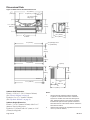
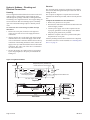
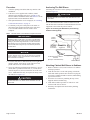
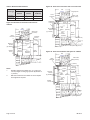
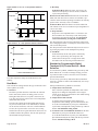
Notes:
1.
Side channels are adjustable from 0" to 9-3/8" in length by inverting them. Side channels are predrilled
to allow infinite adjustment.
2.
Subbase shown with louvered front panel removed.
Front panel is hinged to allow access to valve, coil,
filter & electrical junction box.
3.
Leveling legs are adjustable from 1/4" to 1-1/4".
Hydronic Subbase
A subbase is available as required with all hydronic units.
This subbase measures 8" (203mm) in height and includes
the hydronic heating coil.
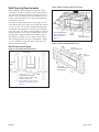
Electrical and plumbing rough-in can be done through the
back of the hydronic heat section or through the openings
provided in the bottom of the subbase. The finished piping
can be done now or later.
When the equipment is received, check it thoroughly for
damage. If any damage is noticed, the carrier should make
proper notation on the delivery receipt acknowledging the
damage. The carrier should also fill out a Carrier Inspection
Report. Our Traffic Department should then be contacted.
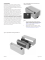
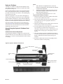
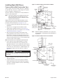
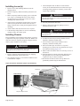
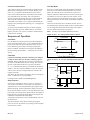
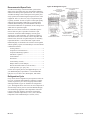
Check the contents of the carton to be sure all the items
shown in Figure 9 have been received. Check the tagging
instructions to be sure the subbase heat section has been
distributed in the correct room.
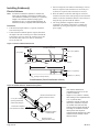
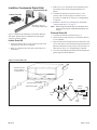
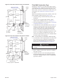
Adjust the side channels as follows:
1. Measure the distance between the finished wall and the
rear face of the subbase heat section.
2. Insert the side channel into the slot of the subbase heat
section and telescope it the appropriate distance as
measured in Step 1.
3. Slide the side channels into the subbase heat section and
fasten securely with the screws provided.
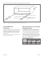
4. Invert the subbase heat section and screw in the leveling
legs. The holes provided for the leveling legs are
extruded to eliminate the need for washers and nuts. The
threads of the leveling legs are self-tapping to assure a
rigid fit.
5. Start the leveling leg into the extruded hole and apply a
wrench to the head. Turn the leg into the hole the desired
distance. Repeat this procedure until all the legs are
installed.
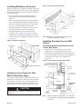
6. Return the subbase heat section to the upright position
and center it under the wall opening.
Assembling the Hydronic Subbase Heat
Section
Subbase Side Channel Adjustment
Telescoping side channels are supplied to extend from the
finished wall to the rear of the subbase heat section. The side
channels are reversible to enable adjustment without cutting
or breaking.
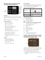
Figure 9: Hydronic Subbase Components
Side Channels
Coil Connection
Cover Plate
Optional Fused
Disconnect
Hydronic Heating
Coil
Permanent Mesh Filter
Leveling Legs (6)
Louvered
Front Panel
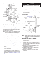
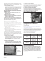
Relocate Indoor Air Sensor
Bulb Holder in Subbase
IM 934-5
Junction Box
Cover Plate
Attach Indoor Air Sensor
Hold-Down Clip To This
Screw
Page 9 of 48