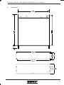
1
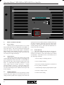
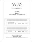
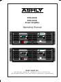
MFA-8000 MFA-6000 Power Amplifier Operating Manual Dual Monaural Amplifier Channel One Output Level -30 -27 -24 -21 -18 -15 -12 -9 -6 Channel Two Output Level -3 0(Clip) -30 -27 -24 -21 -18 -15 -12 -9 Limit -6 -3 0(Clip) Limit Thrm Thrm Protect Protect AC Power MFA-6000 Off On Dual Monaural Amplifier Channel One Output Level -30 -27 -24 -21 -18 -15 -12 -9 -6 Channel Two Output Level -3 0(Clip) -30 -27 -24 -21 -18 Limit Thrm Protect -15 -12 -9 -6 -3 0(Clip) Limit Thrm Protect AC Power MFA-8000 Off On ASHLY AUDIO INC. 847 Holt Road Webster, NY 14580-9103 Phone: (716) 872-0010 Toll-Free: (800) 828-6308 Fax: (716) 872-0739 Internet: http://www.ashly.com/ Operating Manual - MFA-8000 and MFA-6000 Power Amplifier Table Of Contents 2 1 INTRODUCTION . . . . . . . . . . . . . . . . . . . . . . . . . . . . . . . . . . . . . . . . . . . . . . . . . 4 2 UNPACKING . . . . . . . . . . . . . . . . . . . . . . . . . . . . . . . . . . . . . . . . . . . . . . . . . . . . . . 4 3 AC POWER REQUIREMENTS . . . . . . . . . . . . . . . . . . . . . . . . . . . . . . . . . . . . . . 3.1 AC Voltage Requirements. . . . . . . . . . . . . . . . . . . . . . . . . . . . . . . . . . . . . . . . . . 3.2 Current Requirements . . . . . . . . . . . . . . . . . . . . . . . . . . . . . . . . . . . . . . . . . . . . . 3.3 AC Grounding Requirements . . . . . . . . . . . . . . . . . . . . . . . . . . . . . . . . . . . . . . . 4 CABLE REQUIREMENTS . . . . . . . . . . . . . . . . . . . . . . . . . . . . . . . . . . . . . . . . . . 5 4.1 Input Cables. . . . . . . . . . . . . . . . . . . . . . . . . . . . . . . . . . . . . . . . . . . . . . . . . . . . . 5 4.2 Output Cables . . . . . . . . . . . . . . . . . . . . . . . . . . . . . . . . . . . . . . . . . . . . . . . . . . . 5 5 RACK-MOUNTING REQUIREMENTS. . . . . . . . . . . . . . . . . . . . . . . . . . . . . . . 5 5.1 Mechanical . . . . . . . . . . . . . . . . . . . . . . . . . . . . . . . . . . . . . . . . . . . . . . . . . . . . . 5 5.2 Cooling . . . . . . . . . . . . . . . . . . . . . . . . . . . . . . . . . . . . . . . . . . . . . . . . . . . . . . . . 5 6 FRONT PANEL FEATURES. . . . . . . . . . . . . . . . . . . . . . . . . . . . . . . . . . . . . . . . . 6.1 Power Switch. . . . . . . . . . . . . . . . . . . . . . . . . . . . . . . . . . . . . . . . . . . . . . . . . . . . 6.2 Output Meters . . . . . . . . . . . . . . . . . . . . . . . . . . . . . . . . . . . . . . . . . . . . . . . . . . . 6.3 Clipping Indicator . . . . . . . . . . . . . . . . . . . . . . . . . . . . . . . . . . . . . . . . . . . . . . . . 6.4 Limit Indicator . . . . . . . . . . . . . . . . . . . . . . . . . . . . . . . . . . . . . . . . . . . . . . . . . . 6.5 Thermal Indicator . . . . . . . . . . . . . . . . . . . . . . . . . . . . . . . . . . . . . . . . . . . . . . . . 6.6 Protect Indicator . . . . . . . . . . . . . . . . . . . . . . . . . . . . . . . . . . . . . . . . . . . . . . . . . 7 REAR PANEL FEATURES . . . . . . . . . . . . . . . . . . . . . . . . . . . . . . . . . . . . . . . . . . 8 7.1 Inputs . . . . . . . . . . . . . . . . . . . . . . . . . . . . . . . . . . . . . . . . . . . . . . . . . . . . . . . . . . 8 7.2 Normal/Bridging Switch . . . . . . . . . . . . . . . . . . . . . . . . . . . . . . . . . . . . . . . . . . 9 7.3 Stereo/Parallel Mono Switch . . . . . . . . . . . . . . . . . . . . . . . . . . . . . . . . . . . . . . . 9 7.4 Level Controls . . . . . . . . . . . . . . . . . . . . . . . . . . . . . . . . . . . . . . . . . . . . . . . . . . . 9 7.5 Speaker Outputs - Binding Posts . . . . . . . . . . . . . . . . . . . . . . . . . . . . . . . . . . . . 9 7.6 Speaker Outputs - Speakon Connectors . . . . . . . . . . . . . . . . . . . . . . . . . . . . . 10 8 INPUT OPTIONS . . . . . . . . . . . . . . . . . . . . . . . . . . . . . . . . . . . . . . . . . . . . . . . . . 8.1 Input Isolation Transformer . . . . . . . . . . . . . . . . . . . . . . . . . . . . . . . . . . . . . . . 8.2 Peak Limiter Compressor . . . . . . . . . . . . . . . . . . . . . . . . . . . . . . . . . . . . . . . . . 8.3 Two-Way Crossover . . . . . . . . . . . . . . . . . . . . . . . . . . . . . . . . . . . . . . . . . . . . . 8.4 Mic-Line Mixer . . . . . . . . . . . . . . . . . . . . . . . . . . . . . . . . . . . . . . . . . . . . . . . . . 4 4 4 5 6 6 6 6 6 7 7 10 10 10 10 10 Operating Manual - MFA-8000 and MFA-6000 Power Amplifier 9 TYPICAL APPLICATIONS . . . . . . . . . . . . . . . . . . . . . . . . . . . . . . . . . . . . . . . . 9.1 Stereo Operation . . . . . . . . . . . . . . . . . . . . . . . . . . . . . . . . . . . . . . . . . . . . . . . . 9.2 Parallel Mono Operation . . . . . . . . . . . . . . . . . . . . . . . . . . . . . . . . . . . . . . . . . 9.3 Bridged Mono Operation . . . . . . . . . . . . . . . . . . . . . . . . . . . . . . . . . . . . . . . . . 12 12 12 13 10 DESIGN THEORY . . . . . . . . . . . . . . . . . . . . . . . . . . . . . . . . . . . . . . . . . . . . . . . . 13 11 TROUBLESHOOTING TIPS . . . . . . . . . . . . . . . . . . . . . . . . . . . . . . . . . . . . . . . 11.1 No Audio Output . . . . . . . . . . . . . . . . . . . . . . . . . . . . . . . . . . . . . . . . . . . . . . . 11.2 Distorted Sound . . . . . . . . . . . . . . . . . . . . . . . . . . . . . . . . . . . . . . . . . . . . . . . . 11.3 Hum or Buzz Noise . . . . . . . . . . . . . . . . . . . . . . . . . . . . . . . . . . . . . . . . . . . . . 14 14 14 14 12 DIMENSIONS . . . . . . . . . . . . . . . . . . . . . . . . . . . . . . . . . . . . . . . . . . . . . . . . . . . . 15 13 SPECIFICATIONS . . . . . . . . . . . . . . . . . . . . . . . . . . . . . . . . . . . . . . . . . . . . . . . . 16 14 WARRANTY POLICY . . . . . . . . . . . . . . . . . . . . . . . . . . . . . . . . . . . . . . . . . . . . . 17 Caution: This power amplifier can produce dangerous output voltage levels, high power levels, and high sound pressure levels in loudspeakers. In order to minimize the risk of injury, damage, or hearing loss, please read the entire owner's manual before connecting to a sound system. 3 Operating Manual - MFA-8000 and MFA-6000 Power Amplifier 1. INTRODUCTION The MFA Series amplifiers achieve the very high energy levels used in today’s professional sound systems, carefully maintaining control and accuracy while delivering high power to modern loudspeaker configurations. The MFA 8000 (MFA 6000) will deliver 1200 Watts (800W) per channel into 4Ω, and up to 3000 Watts (1800W) bridged-mono into 4Ω. They are Ashly Audio’s highest-powered amplifiers, employing an advanced power supply circuit capable of delivering continuous high current to the most demanding loads. The MFA amplifiers have a dual-monaural design with completely independent, yet physically identical channel modules, offering superior audio performance, better weight distribution, and greater reliability. In order to fully benefit from the many features designed into this product, please take time to read this entire manual before operating. to hard clipping, overheating, excessive high frequency energy, and output DC, thus preventing damage to the amplifier or the load. Status LEDs indicate fault conditions, if any, and warn the operator of situations requiring a change in operating environment. The MFA amplifiers are compatible with all Ashly Powercard input options, and are shipped standard with balanced XLR, 1/4" TRS and screw terminal input connections, as well as 5-way binding post and Neutrik Speakon speaker connections. Stereo, parallel mono, and bridge mode switches along with a ground lift are all externally accessible on the back panel. 2. UNPACKING Caution: This product can deliver enough energy to the output terminals to produce a lethal shock. Do not attempt to wire the amplifier when the power is turned on. As a part of our system of quality control, every Ashly product is carefully inspected before leaving the factory to ensure flawless appearance. After unpacking, please inspect for any physical damage. Save the shipping carton and all packing materials , as they were carefully designed to reduce to minimum the possibility of transportation damage should the unit again require packing and shipping. In the event that damage has occurred, immediately notify your dealer so that a written claim to cover the damages can be initiated. Caution: The MFA amplifiers are capable of delivering tremendous amounts of power to the speaker load. Ashly Audio is not responsible for speaker damage as a result of excessive power. The right to any claim against a public carrier can be forfeited if the carrier is not notified promptly and if the shipping carton and packing materials are not available for inspection by the carrier. Save all packing materials until the claim has been settled. Caution: This unit is capable of producing high sound pressure levels. Continuous exposure to high sound pressure levels can cause permanent hearing impairment or loss. Use caution when operating at high levels by wearing appropriate ear protection. The MFA amplifiers employ complimentary bipolar output transistors to achieve maximum output current capability and power efficiency. All voltage gain and current gain stages remain completely discrete and fully complimentary for lowest distortion and superior overload behavior. 3. 3.1 Voltage Requirements Your MFA amplifier is supplied with an AWG 12/ 3 AC power cord, and should be plugged into a standard 3-wire grounded electrical outlet which supplies 120VAC 50-60 Hz , 15 Amps minimum (some export models are wired for 240 volts and are labeled as such). Be certain that there are no other high-current devices on your AC line, as performance of both may be compromised. In the event of line voltage sag, or “brown-out”, MFA amplifiers will continue to operate normally, albeit with less power. 3.2 In addition to the amplifier’s audio path, several sophisticated monitoring and control circuits serve to keep the amplifier running comfortably within its safe operating area, while protecting the speaker loads from abnormal conditions. This protection will intelligently respond 4 AC POWER REQUIREMENTS Current Requirements A 15 amp circuit is usually sufficient for normal operation into 8Ω or 4Ω loads. The actual AC current consumption by the amplifier depends greatly on the audio signal and the load impedance. For typical audio program material with the amplifier driving both channels just Operating Manual - MFA-8000 and MFA-6000 Power Amplifier peaking at the clipping level, the following AC line current capacities are recommended for system design purposes: Load MFA-6000 MFA-8000 Idle 8Ω × 2 4Ω × 2 2Ω × 2 1 Amp 7.5 Amps 10 Amps 15 Amps 1.2 Amps 10 Amps 15 Amps 20 Amps Table 3.1: Recommended AC line current capacity Both MFA amplifiers consume less than 12 amps when operating at 1/8 power into 2Ω loads. This condition satisfies the UL, CSA and building electrical code requirements for a piece of audio equipment not to consume more than 80% of the current available when plugged into a grounded 15 amp outlet and operated at 1/8 of maximum power. AC Grounding Requirements To reduce the risk of ground loop hum, all system ground references should originate at the same point in your AC power distribution. Never remove the amplifier’s ground pin as it is both unlawful and dangerous, creating a potential shock hazard. Since power at the speaker load is a primary concern in system design, we have included a table to best determine appropriate wire gauge for your application. Table 4.1 lists the percentage of the speaker load power which would be lost in an arbitrary 100 ft run of 2-conductor cable. This table expresses the power loss as a percentage of the load’s power rather than the total amplifier output power, so that you can use this table to accurately determine power loss at other cable lengths. For example, if you plan to deliver 100 watts to an 8Ω load through 50 ft of 14 ga. cable, the power loss in the cable would be 3.2% ÷ 2 = 1.6% of 100 watts or 1.6 watts lost in the cable. Wire Gauge Ω/100ft 8Ω load 4Ω load 2Ω load 8 10 12 14 16 18 .0605Ω .1018Ω .1619Ω .2575Ω .4094Ω .6510Ω 0.8% 1.3% 2.0% 3.2% 5.1% 8.1% 1.5% 2.5% 4.0% 6.4% 10.2% 16.3% 3.0% 5.1% 8.1% 12.9% 20.5% 32.6% 3.3 4. CABLE REQUIREMENTS 4.1 Input Cables Be sure to use shielded cable whether balanced or unbalanced. Shielding which is properly grounded will protect the signal from outside electrical interference such as RF, fluorescent lighting, even computer noise. As a general rule, unbalanced or single-ended (tip-sleeve) lines of less than 10 feet are satisfactory, but greater distances may require a balanced signal. Avoid running input lines in close proximity or parallel to long speaker lines, AC power cables, or power transformers, as this may generate hum or oscillation. 4.2 Output Cables The MFA amplifiers are capable of delivering high levels of output current, therefore the wire gauge used for speaker cables is particularly important. Inadequate wire gauge adds significant resistance to the speaker’s own impedance, reducing the power which is actually delivered to the speaker. It will also result in a decrease in the damping factor and possible fire hazard. Table 4.1: Percentage of speaker load power lost in 100 foot run of 2-conductor cable. 5. RACK-MOUNTING REQUIREMENTS 5.1 Mechanical All Ashly amps are designed to fit in standard 19inch racks. The front panel rack-mount ears are sufficiently strong for most applications. If you desire further integrity for mobile racks, we recommend using the four additional holes in the back of the chassis for supplemental rear-mounting (see dimensional drawings). 5.2 Cooling Be certain that both the front and back of the rack have unhindered access to free air flow. Fan direction is from front to back. It is not necessary to leave empty space above or below the amplifier for cooling purposes. Thermal output of the amp is measured in max BTU/hour for typical audio program material when both channels are just peaking at the clipping level. Load Idle 8Ω 4Ω 2Ω MFA-6000 MFA-8000 420 1900 2300 4140 500 2420 3450 4830 Table 5.1: Maximum BTU/hour 5 Operating Manual - MFA-8000 and MFA-6000 Power Amplifier Channel One Output Level -30 -27 -24 -21 -18 -15 -12 -9 -6 -3 0(Clip) Limit Thrm Protect AC Power Off 6. FRONT PANEL FEATURES 6.1 Power Switch When the unit is switched on there is a 2 second delay, during which time the PROTECT and LIMIT circuits will activate. The load is disconnected during this power-up sequence, and the input signal is attenuated. When turning off the amplifier, the load is removed instantly, and the protect and limit LEDs will briefly turn on as the power supply discharges. 6.2 Output Meters Output meters display peak output voltage in dB, referenced to full output. For example, if full output in a given configuration is 800 watts, then “0” on the LED display means the amp is delivering the full 800 watts to the load, “-6” would mean the output is 6dB down, or 200 watts (-6dB is half the voltage, and power = voltage squared divided by resistance ). If the line voltage sags, the output meters will track the drop and accurately preserve the relationship between “dB below full output” and actual clipping. On signal peak levels extend beyond the available power supply rails, essentially “cutting off” the crest portion of the waveform. This produces signal distortion, and can potentially damage drivers. The CLIP LED illuminates exactly at the onset of clipping. 6.4 Limit Indicator This green LED indicates that the internal electronic limiter has activated, in the form of a signal attenuator. The intensity of the LED indicates the amount of attenuation. The limiter circuit is activated by any of the following conditions: 1. Turn-on delay for muting purposes 2. Severe output clipping 3. Excessive internal temperature (monitored at two key points per channel) 4. Abnormal high frequency/high amplitude signal 5. Excessive output current 6.3 Clipping Indicator The red CLIP LED is a true clip indicator, which monitors the power supply as it is affected by the AC line voltage and the speaker load. Clipping occurs when the 6 6. Protect-mode muting Operating Manual - MFA-8000 and MFA-6000 Power Amplifier Dual Monaural Amplifier Channel Two Output Level -30 -27 -24 -21 -18 -15 -12 -9 -6 -3 0(Clip) Limit Thrm Protect MFA-8000 6.5 Thermal Indicator This yellow LED indicates that the internal temperature of the amplifier is too high in one or more places. Intensity of the LED is proportional to temperature above normal. Note that if the thermal LED occasionally comes on dimly, this is not considered excessive. If, however, the thermal LED illuminates brightly, the limiter circuit will activate and attenuate the input signal until operating temperature returns to an acceptable range. If the thermal LED remains brightly illuminated, the amplifier’s operating temperature should be reduced by one or more of the following actions: 1. Turn-on delay 2. Instant turn off 3. Extreme internal temperature (this will only occur after other thermal management efforts within the amplifier have failed to bring internal operating temperatures within safe levels) 1. Turn down the applied input signal 4. Abnormal high frequency/high amplitude signal 2. Allow better ventilation around the amplifier 5. DC voltage at the output (signals below 8 hertz will be interpreted as DC voltage, and may trigger the protect circuit) 3. Increase the speaker load impedance by disconnecting some speakers 6.6 cuit is activated for maximum muting. Conditions causing the amplifier to switch into protect mode include the following: Protect Indicator Protect mode in ASHLY amplifiers is automatically activated during extreme fault conditions, as well as during power-up and power-down . When in protect mode, as indicated by the red LED, the speaker output terminals are internally disconnected and the limiter cir- 6. Output short circuit After the abnormal condition ceases, the amplifier will automatically recover from protect mode. 7 Operating Manual - MFA-8000 and MFA-6000 Power Amplifier Normal Bridging -2 Stereo Parallel Mono 0 -2 0 - - Parallel Mono Mode ties Ch.1 and Ch.2 inputs together, using seperate level controls for each channel. -6 -20 Bridge Mode uses Ch.1 input and Ch.1 -10 level control, overriding stereo/mono switch. Channel Two Take output from two red binding posts. -6 -20 -10 Channel One Input Ground (-) (+) Channel Two Input (-) Chassis Ground (+) Channel One Input (Bridged Input) Figure 7: Input Section 7. REAR PANEL FEATURES 7.1 Inputs The standard input panel of the MFA series amps is equipped with balanced 1/4" tip-ring-sleeve (TRS) phone jacks, balanced XLR jacks, and balanced screwterminal inputs. The three types of connectors are internally wired in parallel and may be used with balanced or unbalanced connections. The inputs are configured for pin 2 hot, meaning that a positive voltage applied to pin 2 will result in a positive output voltage across the speaker terminals. Pin 2 of the XLR jack is equivalent to the tip of the 1/4" TRS jack. An optional input transformer is available on all MFA amplifiers. Figure 7.1: Balanced Input Connections Balanced Inputs It is recommended that balanced input connections be used whenever possible to reduce ground-loop and environment-induced hum and noise. The (+) signal is on pin 2 of the XLR, and the tip of the phone jack. The (-) signal is on pin 3 of the XLR, and the ring of the phone jack. Unbalanced Inputs If an unbalanced input connection is used, then the (-) connection (XLR pin 3) should be connected to input ground ( XLR pin 1). If the 1/4" input jack is used unbalanced, the use of a mono (tip-sleeve) plug will automatically tie the (-) connection to input ground. Never float pin 2 or pin 3 when using an unbalanced signal. Figure 7.1a: Unbalanced Input Connections 8 Operating Manual - MFA-8000 and MFA-6000 Power Amplifier Input Ground The CHASSIS GROUND terminal is internally connected to the chassis, the AC earth ground, and the power amplifier’s signal ground. The INPUT GROUND terminal is tied to the XLR pin 1 and the 1/4" jack sleeve. It is recommended that the input and chassis ground terminals remain connected with the factory-supplied jumper strap. In situations where the power amp and its signal source are separated by great distances, a ground voltage difference may exist between the amp’s chassis ground and the input cable’s ground. Connection of these two grounds through the jumper strap may cause large ground currents to flow (which is known as a ground loop), causing a hum noise in the amp’s output. Unless you have such a situation with a hum problem that cannot be solved by using balanced input connections, the ground jumper strap should remain in place. 7.2 Normal/Bridging Switch This switch selects between NORMAL mode in the “out” position where both channels are in-phase, and BRIDGING mode in the “in” position where channel 1 input is used to drive both channels, inverting the phase of channel 2. In BRIDGING mode, the channel 1 red binding post is the (+) in- phase speaker output terminal and the channel 2 red binding post becomes the (-) out-of-phase speaker terminal. It is not necessary to depress the MONO switch in order to operate in BRIDGED mode. The BRIDGING switch overrides either setting of the Stereo/ Mono Switch. 7.5 Speaker Outputs - Binding Posts Caution: This product can deliver enough energy to the output terminals to produce a lethal shock. Do not attempt to wire the amplifier when the power is turned on. CHANNEL 1 OUTPUT 1+ is POS 1- is GND Ashly Mad MF 1 5 (-) an.1 n 1+, Pin1an.2 n 2+, Pin2- (+) (+) BRIDGE (-) al Channel nnector dged ono Mode: n 1+ is pos n 2+ is neg 750 W 1200 W (+) (-) 7.3 Stereo/Parallel Mono Switch This switch selects between STEREO mode in the “out” position and PARALLEL MONO mode in the “in” position. In PARALLEL MONO mode, channel 1 and channel 2 inputs are internally tied together before the input attenuator, allowing discrete channel control of a mono signal. CAUTION: Be sure not to have two signal sources connected to ch.1 and ch.2 inputs when in parallel mono mode, as it would short-circuit these two signals and result in no output. 7.4 Level Controls The level controls allow attenuation (calibrated in dB) of the input signal. In PARALLEL MONO mode, channel 1 and channel 2 inputs are tied together, while still preserving independent level control per channel. In BRIDGED mode, use only channel 1 level control. It is recommended that the level controls be operated at full level (0 dB attenuation) in most situations to maximize the headroom in the signal source. 1+ is POS 1- is GND MDA 20A CHANNEL 2 OUTPUT Channel 2 Figure 7.5: Output Section A pair of dual banana binding posts provide the stereo speaker outputs. In BRIDGING mode, the channel 1 red binding post is the (+) in-phase speaker output terminal and the channel 2 red binding post becomes the (-) out-of-phase speaker terminal. CAUTION! NEVER CONNECT THE TWO RED BINDING POSTS TOGETHER OR CONNECT EITHER RED BINDING POST TO A BLACK BINDING POST! 9 Operating Manual - MFA-8000 and MFA-6000 Power Amplifier 7.6 Speaker Outputs - Speakon Connectors Neutrik Speakon connectors are provided to connect with the Neutrik NL4FC 4-conductor plug. For the channel 1 and 2 Speakon connectors, the following pin assignment is used: Pin 1+ = speaker hot 8.2 Peak Limiter/Compressor The limiter input option provides peak signal limiting from excessive input levels for speaker protection and overall level control. Separate limiter threshold controls, limit indicator LED’s and limit on/off switches are provided on each channel allowing fully discrete stereo limiting operation. Pin 1- = speaker ground The third Speakon connector in the center provides a stereo connection if operating in stereo mode or a bridged connection if operating in bridged mode. The pin assignment for this connector is: Stereo Mode Bridged Mode Pin 1+ = Ch.1 hot Speaker hot 8.3 Pin 1- = Ch.1 ground Pin 2+ = Ch.2 hot Speaker return Pin 2- = Ch.2 ground 8. INPUT OPTIONS Input option panels are available to provide builtin features such as a stereo compressor-limiter, a mic and line mixer, a crossover for bi-amplified systems, and input transformers for signal isolation. In addition to the MFA amplifiers, all FTX MOS-FET amps, the CFT-1800 convection cooled amp, and P70 series 70 volt amps will accept Ashly input option panels. A brief description of currently stocked input options follows. Consult your dealer for detailed information on input options, or call the factory. Two-Way Crossover The crossover input option provides fixed-frequency 24 dB/octave high-pass and low pass filters allowing the two amplifier channels to operate bi-amped, full range with low out, both channels low out, or bridged low out. Auxiliary low and high outputs are available for connecting additional amplifiers. Included with the crossover input option are single in-line package (SIP) resistor networks which allow preselection between standard crossover frequencies of 160Hz, 500Hz, 750Hz, 1.2KHz, and 1.6KHz. 360° of phase control is provided for proper acoustical alignment of high and low frequency drivers. Selectable constant directivity horn EQ is provided for both small and large horn designs. 8.4 8.1 Input Isolation Transformer The input isolation transformer can be installed directly into the standard input supplied with every ASHLY amplifier (except for the single rack space SRA120). The input transformer provides complete electrical isolation from the amplifier and its signal source to eliminate any ground-induced hum noise. The transformer input also further reduces any common-mode noise and radio frequency interference. The transformer option is installed within the standard input panel and does not change the operation of any switches or controls. 10 Six Input Mic-Line Mixer The mixer input option provides four high-impedance line inputs and two balanced low-impedance microphone inputs, each with its own level control. A switchable 200 Hz high-pass filter is provided on the mic inputs to reduce unwanted low frequency noise. An internal jumper allows selection of 15 Volt phantom power applied to the mic inputs for use with condenser mics. The option has a master level control and selectable stereo, mono and bridging modes. Insert Points are available for patching external processing into the left and right channels. Operating Manual - MFA-8000 and MFA-6000 Power Amplifier Ch.2 Limiter Threshold Limit (dB) +18 +15 +6 +3 0 -3 Stereo Mono Ch.1 Limiter Threshold Limit (dB) Norm Bridge -28 +18 +15 +6 +3 0 -3 -12 -9 -6 CL-2 POWERCARD Input Option Stereo Limiter -28 -12 -9 -6 PUSH Input Ground 4 5 6 3 2 1 Figure 8.2: CL-2 Peak Limiter Compressor PUSH PUSH (+) (-) (-) 4 5 6 (+) 1 9 10 0 7 8 9 0 Limiter Level In/Out Chassis Ground Channel 2 Output Modes Low Level 10 10 Ch.2 Ch.1 1.Low High (FR) 2.Low Low 3.Bridged Low Ch.2 is (+) 5 PUSH dB 0 +180 +360 CD Horn EQ 0 +180 1.2KHz 2.4KHz Off 5 (-) Installed Crossover Frequency: 0 Highpass Full Range CAUTION: Never Send Full Range Signal To High Frequency Drivers. -∞ XR-1 POWERCARD Input Option Two-Way 24dB/Oct. Crossover Input Ground (+) Limiter In/Out Channel 1 (Mono) Phase High (FR) Level 123 0 -1 10 Level Figure 8.3: XR-1 Two-Way Crossover -21 -3 -15 -6 -9 Input Level Microphone Inputs (Mono) -1-210 Aux Low Out (Pre Level) Chassis Ground Balanced Input (Pin 2 Hot) Master Level 0 10 4 0 5 Mic 1 Level 1 PUSH PUSH Phan. (+15V) Mic 2 Level 8 1 9 MM-6 10 POWERCARD L Input Option Mic/Line Mixer PUSH PUSH L 2 4 R 0 10 Ch.1 0 10 Ch.2 0 10 Ch.3 Line Level 0 10 Norm Bridge 7 2 0 3 Stereo Mono 6 3 Low-Cut (Mics Only) Aux High Out (Pre Level) Figure 8.4: MM-6 Mic - Line Mixer Send R Return Ch.4 Line Inputs L = Amplifier Channel 1 Output R = Amplifier Channel 2 Output Mono Mode Sums the Stereo Signals Insert Points (Post Master Level) 11 Operating Manual - MFA-8000 and MFA-6000 Power Amplifier 9. TYPICAL APPLICATIONS 9.1 Stereo Operation (Both switches out, both inputs used, both level controls used, both outputs used) 9.2 Parallel Mono Operation (Parallel mono switch in, channel 1 input used, both level controls used, both outputs used) 12 Operating Manual - MFA-8000 and MFA-6000 Power Amplifier 9.3 Bridged Mono Operation (Normal/bridging switch in, channel 1 input used, channel 1 level control used, BRIDGED output used) 10. DESIGN THEORY The MFA Series amplifiers are based on a dualmonaural design with each channel being electrically and physically identical. This type of design improves audio performance by eliminating power supply interaction and crosstalk. Failure of one channel will not affect the other. Because each channel is physically independent and fully integrated onto its own modular assembly, servicing is simplified. The output stages of the MFA amps use complimentary bipolar power transistors. Bipolar transistors were chosen for maximum power efficiency and greater output current capacity, both of which are particularly important in high-power, low-frequency applications. Like all other Ashly power amps, all power and gain stages are 100% discrete. In other words, there are no op-amps used within the power amp’s main signal path or feedback loop. This results in an exceptionally clean and well behaved output waveform (no glitching or ringing) in the presence of transients or clipping. All power supply high current paths are retained on each channel’s respective PC board, keeping wiring to a minimum. The power supply uses three DC voltage levels which are switched sequentially by ultrafast MOSFETs depending on the demands of the output voltage. This concept is employed for greater power efficiency and to reduce the AC power consumption. Sophisticated power amp monitoring circuits detect any abnormal conditions which may cause damage to the amplifier or speakers. A highly accurate clip detector illuminates the CLIP LED at the onset of clipping. Further increases in signal level will activate a limiter circuit which prevents severe overload distortion from occurring. This limiter circuit illuminates the LIMIT LED when it becomes active, where the light intensity of the LED indicates the amount of signal attenuation. Advanced thermal management circuitry senses temperature at four locations in the amp and adjusts fan speed accordingly. A THERMAL LED on each channel indicates an above normal operating temperature. The light intensity of this LED is an indication of the temperature above normal. If the internal temperature becomes excessive, the limiter circuit will attenuate the input signal until the amplifier returns to a normal operating range. The amplifier’s output will automatically shut down in the event of a fault condition such as severe overheating, shorted output, DC voltage, or extreme high frequency energy. A PROTECT LED indicates when one or more of these abnormal conditions occur. Each channel’s limiting, thermal, and protection management functions are completely independent of the other channel. The MFA Series amplifiers are equipped with the necessary circuitry for computer control and monitoring as this capability becomes available in the future. 13 Operating Manual - MFA-8000 and MFA-6000 Power Amplifier 11. TROUBLESHOOTING TIPS 11.1 No Audio Output Power switch not lit: 11.2 Distorted Sound Output level meters indicate 0dB level (red CLIP LED on): Line fuse is blown or power outlet is dead. Amplifier is being clipped. Reduce the signal level at the signal source. Power switch is lit but no LEDs lit: 0 dB level on output meters is never reached: There is no input signal applied or input level controls are off. Note: In parallel mono mode, be sure that only one signal source is connected to the amp. Applied input signal is distorted before it gets to the amp. Check to see if a piece of equipment in the signal chain before the amp is clipping. Normally the amplifier should be operated with input levels fully CW to maximize headroom in the signal source. Also check for damaged speaker drivers that could cause distorted sound. Protect LED and Limit LEDs are lit and relay clicking is heard: Output is short circuited or load impedance is too low. Check speaker cables for shorts, increase load impedance by disconnecting some speakers. A high frequency oscillation in the sound system is occurring when the relays close. Turn down the input level controls to verify that the amplifier alone is not causing the problem. Be sure to use good quality shielded and balanced input cables. Do not run input cables alongside output speaker wires over long lengths. Protect and Limit LEDs are lit, Clip LED comes on as soon as input signal is applied: DC voltage may be present on the output or an internal 15 amp type MDA slow acting fuse on the amplifier circuit board may be blown. Have a qualified technician replace the fuse with the same type of fuse. Protect LED and Limit LED only are lit: This is the normal status for the first 2 seconds after switching power on. If this status continues, the amplifier may be protecting the speak ers from an abnormally high frequency and high amplitude signal. The problem may be with the signal source. Try disconnecting the signal source from the amp. Protect LED and Thermal LED are lit: Amplifier is in thermal protect mode due to extreme overheating. Allow better ventilation, reduce signal levels or increase load impedance by disconnecting some speakers. 14 If distorted sound is still heard, there may be an internal problem. Call Ashly Audio service department at 800-828-6308. 11.3 Hum or Buzz Noise Be sure that the power cord’s 3-prong plug is connected to a properly earth-grounded outlet. Lifting the grounding third prong usually does not improve hum or buzz and creates a potential electrical shock hazard. Use balanced input connections with a balanced audio source for best hum and buzz rejection. See section 7.1 on inputs. Normally the ground lift strap on the input screw terminals should be left in place for best ground voltage suppression. In some cases hum or buzz noise may be induced by excessive ground current through the input ground connection. This current path may be interrupted by removing the ground lift strap. If the problem persists, input signal transformers providing complete ground isolation are available. See section 8.1 on Input Isolation Transformer. Buzz noise can be caused by lighting dimmers or neon lights. Try moving the amplifier, wiring, or lighting to different locations to see if lighting is the source of the buzz. Input transformers may also fix the problem. See section 8.1 on Input Isolation Transformer. Operating Manual - MFA-8000 and MFA-6000 Power Amplifier 12. DIMENSIONS 15 Operating Manual - MFA-8000 and MFA-6000 Power Amplifier 13. SPECIFICATIONS 13.1 Output Power Per channel, both channels driven at 1KHz, < .1% THD, 120VAC 60Hz 8Ω: 4Ω: 2Ω: 13.9 Input Impedance: 20KΩ balanced MFA-8000 MFA-6000 13.10 Amplifier Protection: Fuseless Short-circuit protection, ultrasonic and RF protection, advanced thermal protection. 750W 1200W 1500W 525W 800W 900W 13.11 Load Protection: Turn-on delay relay with level ramp-up, DC fault protection, ultrasonic limiting, clip limiting. bridged mono mode 8Ω: 4Ω: 2400W 3000W 1600W 1800W (±1dB) per channel from 20Hz to 12KHz*, < .25% THD 8Ω: 4Ω: 13.2 13.3 13.4 720W 1100W 450W 700W Frequency Response: ± 0.2dB 20Hz - 20KHz +0/-3dB 8Hz - 100KHz Total Harmonic Distortion: < 0.025% (720W [450W for MFA-6000] into 8Ω, 20Hz 1KHz, increasing to < .25% at 12KHz) Output Hum And Noise: -105 dB from full output (20Hz - 20KHz unweighted) 13.5 Damping Factor: > 200 into 8Ω, 20Hz - 1KHz 13.6 Crosstalk: -90dB, 20Hz - 1KHz 13.12 Cooling: Forced air with 2-speed fan. 13.13 Indicators: 11 segment level meters with true clipping top LED. LIMIT LED indicates when electronic attenuator is active, THERM LED indicates a higher than normal operating temperature and PROTECT LED indicates when output relay is open. 13.14 Power Requirements: 120 VAC, 50-60 Hz (240VAC available) Maximum current draw for typical stereo operation into 4Ω loads: MFA-8000 MFA-6000 12 amps 10 amps Idle current draw: 1.2 Amps 13.7 13.8 16 Input Sensitivity: 1 Vrms for full output (MFA-8000) 0.81 Vrms for full output (MFA-6000) Voltage Gain: 80× = 38dB 1 Amp 13.15 Size: 19"W x 5.25"H x 16.5"D 13.16 Shipping Weight: 68lbs. (61lbs.) *Protection circuits will prevent full output voltage above 12KHz. Operating Manual - MFA-8000 and MFA-6000 Power Amplifier 14. WARRANTY POLICY We thank you for your expression of confidence in Ashly products. The unit you have just purchased is protected by a limited five year warranty. To establish the warranty, you must first complete and mail the warranty card attached to your product. Fill out the information below for your records. Model Number _________________________________ Serial Number _________________________________ Dealer ________________________________________ Date of Purchase _______________________________ Dealer’s Address _______________________________ _______________________________________________ Dealer’s Phone _________________________________ Salesperson ____________________________________ OTHER INFORMATION: 17 Operating Manual - MFA-8000 and MFA-6000 Power Amplifier 18 Operating Manual - MFA-8000 and MFA-6000 Power Amplifier 19 Operating Manual - MFA-8000 and MFA-6000 Power Amplifier ASHLY AUDIO INC. 847 Holt Road Webster, NY 14580-9103 Phone: (716) 872-0010 Fax: (716) 872-0739 Toll Free (800) 828-6308 Internet: http://www.ashly.com/ 1997 by Ashly Audio Corporation. All rights reserved worldwide. Printed in USA 8/97 MFA Rev 2