1
ES-5160G+ v2 / ES-5240G+ v2
16 / 24 Ports Gigabit Web Smart Switch with 4 ports mini-GBIC
User’s Manual
Version 1.0 / August, 2010
FCC Certifications
This Equipment has been tested and found to comply with the limits for a Class A
digital device, pursuant to part 15 of the FCC Rules. These limits are designed to
provide reasonable protection against harmful interference when the equipment
is operated in a commercial environment. This equipment generates, uses, and
can radiate radio frequency energy and, if not installed and used in accordance
with the instruction manual, may cause harmful interference to radio
communications.
Operation of this equipment in a residential area is likely to cause harmful
interference in which case the user will be required to correct the interference at
his own expense.
This device complies with Part 15 of the FCC Rules. Operation is subject to the
following two conditions: (1) this device may not cause harmful interference, and
(2) this device must accept any interference received; including interference that
may cause undesired operation.
CE Mark Warning
This equipment complies with the requirements relating to electromagnetic
compatibility, EN 55022 class A for ITE, the essential protection requirement of
Council Directive 2004/108/EC on the approximation of the laws of the Member
States relating to electromagnetic compatibility.
Company has an on-going policy of upgrading its products and it may be possible
that information in this document is not up-to-date. Please check with your local
distributors for the latest information. No part of this document can be copied or
reproduced in any form without written consent from the company.
Trademarks:
All trade names and trademarks are the properties of their respective companies.
Copyright © 2010, All Rights Reserved.
1
Table of Contents
Unpacking Information ............................................................. 5
Introduction.............................................................................. 5
General Description ...................................................................5
Key Features.............................................................................6
The Front Panel .........................................................................6
LEDs Definition ......................................................................6
The Rear Panel ..........................................................................8
Installation ............................................................................... 9
Desktop Installation ...................................................................9
Rack-mount Installation .............................................................9
Installing Network Cables ......................................................... 10
Functional Description .............................................................11
Jumbo Frame .......................................................................... 11
Flow Control and Back Pressure................................................. 11
Mirror..................................................................................... 11
VLAN ..................................................................................... 11
Trunk (Aggregation) ................................................................ 11
Quality of Service (QoS) ........................................................... 11
SNMP ..................................................................................... 11
Management guide ..................................................................12
Access the management interface of the Switch .......................... 12
Manage the device via command line interface......................... 12
Manage the device via WEB browser ....................................... 12
System .................................................................................. 14
Port ....................................................................................... 16
VLAN ..................................................................................... 17
2
PVID ...................................................................................... 19
Aggregation/ Trunk Configuration .............................................. 20
LACP ...................................................................................... 21
RSTP...................................................................................... 22
802.1x ................................................................................... 24
IGMP Snooping........................................................................ 27
Quality of Service .................................................................... 28
Mirror..................................................................................... 30
Rate Limit............................................................................... 31
Storm Control ......................................................................... 32
Statistics Overview .................................................................. 32
Detailed Statistics.................................................................... 33
LACP Status ............................................................................ 34
RSTP Status............................................................................ 35
IGMP Status............................................................................ 36
Ping ....................................................................................... 37
Warm Restart.......................................................................... 38
Factory Default........................................................................ 38
Software Upload ...................................................................... 38
Product Specifications .............................................................39
Appendix- Command Line Interface .........................................40
Start-up and Terminal configuration........................................... 40
Login/Logout Procedures .......................................................... 40
Command Hierarchy ................................................................ 41
Entering Commands................................................................. 41
Command Description .............................................................. 42
System Commands .............................................................. 42
Console Commands .............................................................. 45
Port Commands ................................................................... 46
3
MAC Commands................................................................... 48
VLAN Commands.................................................................. 50
Aggregation Commands ........................................................ 52
LACP Commands .................................................................. 53
RSTP Commands.................................................................. 54
User Group Commands ......................................................... 57
QoS Commands ................................................................... 58
Mirror Commands................................................................. 61
IP Commands ...................................................................... 62
Dot1x Commands................................................................. 64
IGMP Commands.................................................................. 66
Debug Commands ................................................................ 67
4
Unpacking Information
Thank you for purchasing the 16/24-Port Gigabit Web Smart Switch with
4-Port mini-GBIC. Before you start, please verify that your package contains
the following items:
1.
2.
3.
4.
One 16/24-Port Gigabit Web Smart Switch with 4-Port mini-GBIC.
One power cord.
Rack-mount brackets and screws (optional).
Manual CD.
Introduction
General Description
Easily boosting your networking throughput, the 16/24-Ports Gigabit Web
Smart Switch provides you 16/24 10/100/1000 Mbps gigabit ports that lead
you to a real gigabit connection. Users are now able to transfer high
bandwidth-demanded files faster and get a real efficiency improvement with
the user-friendly Web-based management interface. This product also
equips 4 mini GBIC slots for your flexible fiber connection. Use of the
mini-GBIC port disables the connection of its corresponding copper port
automatically.
The management functionalities provide efficient network usage. VLAN
reduces the collisions from widely broadcasting. Port Aggregation enlarges
the bandwidth of backbone connection. QoS is supported to secure the
bandwidth for some bandwidth-demanded applications including VoIP or
videoconference. The 802.3x and backpressure flow control mechanisms
are also supported to ensure the correctness of data transmitting.
5
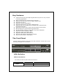
Key Features
16/24 fixed 10/100/1000 Mbps Gigabit Ethernet ports for easy network
connecting application.
Equips 4 SFP ports for optional fiber connection.
Supports auto-detection for mini-GBIC module inset.
Supports Port Mirror.
Supports 8 groups aggregation.
Supports QoS function, tag base, DSCP priority.
Supports Rate Limit (ICMP Rate, Broadcast Rate, Multicast Rate,
Ingress/Egress Rate).
Supports full duplex flow control and half duplex back pressure.
Non-blocking wire-speed switching performance.
Provides 8K MAC address entries and 16 groups VLAN table.
Supports firmware upgrade, SNMP.
Supports Jumbo frame 9600 bytes.
Supports 500K bytes buffer Memory.
Supports Web-based management interface.
FCC, CE, VCCI Class A. Meet RoHS.
The Front Panel
The front panel consists of the ports and LED indicators. Please refer to the
following paragraph for information.
LEDs Definition
LED for the device:
The switch provides a power LED for the device.
LED
Power
Status
Steady Green
Off
6
Operation
The switch is powered on
The switch is powered off
LED for each port:
The switch provides one “1000M” LED and one “10/100M” LED for each port.
1000M LED: Shows the current transmitting/receiving speed of the port.
10/100M LED: Shows the link status and the activities on the port.
LED
Status
Green
1000M
10/100M
Operation
The port is connected at 1000 Mbps.
A valid link is established, and there is data
Blinking Green
transmitting/receiving.
No valid link on this port or the port is connected
Off
at 10/100 Mbps.
A valid link is established, and there is no data
Steady Green
transmitting/receiving.
A valid link is established, and there is data
Blinking Green
transmitting/receiving.
No valid link on this port or the port is connected
Off
at 1000 Mbps.
Attention:
:The Mini GBIC slot shares the same LED indicator with the
last 4 RJ-45 (copper) ports.
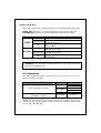
Port Operation
The auto-negotiation feature allows those ports running at one of the
following operation modes:
Media
Speed
1000 Mbps
Duplex Mode
Full Duplex
Half Duplex
Full Duplex
Half Duplex
Full Duplex
1000 Mbps
Full Duplex
10 Mbps
10/100/1000 Mbps(copper)
100 Mbps
1000 Mbps(Fiber)
(mini-GBIC required)
Note: For the last port, when both the fiber and cooper interfaces are
connected, the system adapts the fiber interface and disables the relevant
cooper port automatically.
7
Restore Default Button
You can use this button to reset the switch or restore factory default settings.
To reset the switch, press the button once.
To restore factory default settings, press and hold the button for three
seconds.
The Rear Panel
The rear panel of the switch:
Power Receptacle
To be compatible with the electric service standards around the world, the
switch is designed to afford the power supply in the range from 100 to 240
VAC, 50/60 Hz. Please make sure that your outlet standard to be within this
range.
To power on the switch, please plug the female end of the power cord firmly
into the receptacle of the switch and the other end into an electric service
outlet. After the power cord installation, please check if the power LED is lit
for a normal power status.
8
Installation
This switch can be placed on your desktop directly, or mounted in a rack.
Please refer to the instructions for installation.
Before installing the switch, we recommend:
1.
2.
3.
The switch is placed with appropriate ventilation environment. A
minimum 25 mm space around the unit is recommended.
The switch and the relevant components are away from sources of
electrical noise such as radios, transmitters and broadband amplifiers
The switch is away from environments beyond recommend moisture
Desktop Installation
1.
2.
Install the switch on a level surface that can support the weight of the
unit and the relevant components.
Plug the switch with the female end of the provided power cord and plug
the male end to the power outlet.
Rack-mount Installation
The switch may be standalone, or mounted in a rack. Rack mounting
facilitate to an orderly installation when you are going to install series of
networking devices.
Procedures to Rack-mount the Switch:
1.
2.
3.
4.
5.
6.
7.
Disconnect all the cables from the switch before continuing.
Place the unit the right way up on a hard, flat surface with the front
facing you.
Locate a mounting bracket over the mounting holes on one side of the
unit.
Insert the screws and fully tighten with a suitable screwdriver.
Repeat the two previous steps for the other side of the unit.
Insert the unit into the rack and secure with suitable screws (optional).
Reconnect all the cables.
9
Installing Network Cables
1. Crossover or straight-through cable: All the ports on the switch
support Auto-MDI/MDI-X functionality. Both straight-through or
crossover cables can be used as the media to connect the switch with
PCs as well as other devices like switches, hubs or router.
2. Category 3, 4, 5 or 5e, 6 UTP/STP cable: To make a valid connection
and obtain the optimal performance. An appropriate cable that
corresponds to different transmitting/receiving speed is required. To
choose a suitable cable, please refer to the following table.
Media
Speed
Wiring
10 Mbps Category 3,4,5 UTP/STP
10/100/1000
100 Mbps Category 5 UTP/STP
Mbps copper
1000 Mbps Category 5e,6 UTP/STP
The cable type differs from the
1000 Mbps Fiber
mini-GBIC you choose. Please refer to
(mini-GBIC
1000 Mbps
the instruction came with your
required)
mini-GBIC.
10
Functional Description
Jumbo Frame
With Jumbo Frame supported, it is allowed for the switch to transport
identical data in fewer frames. Hence helps to ensure fewer overheads,
shorten processing time, and reduce interruptions.
Note: To enable Jumbo Frame, Flow Control should be enabled in advance.
Flow Control and Back Pressure
Flow Control and Back Pressure both contributes for lower and higher speed
devices to communicate to each other hence ensures the correctness of
data transmitting. The 802.3x flow control and Back Pressure mechanisms
work respectively for full and half duplex modes. Flow Control can be
enabled or disabled on a per-port basis.
Mirror
The Mirror function provides network administrator to monitor the traffic. By
forwarding a copy of the packets that transferred by the monitored port, the
sniffer port received all the packets and hence is able to monitor the traffic
of the specified port.
VLAN
With VLAN supported, the network can be segmented in groups to reduce
the collisions from widely broadcasting. The device supports both
port-based VLAN and 802.1Q tag based VLAN. Port-based VLAN classifies
incoming packets to VLANs according to their ingress port. The 802.1Q
based VLAN add a tag to the header of the packet to classify their VLANs.
Trunk (Aggregation)
The Trunk functionality integrates several ports to enlarge the bandwidth
that helps to boost the backbone connectivity. The switch allows the
Maximum 8 groups for each group.
Quality of Service (QoS)
The QoS service classifies packets into different precedence. The packets
are transmitted and received by their classified priorities. This mechanism
helps high bandwidth demanded applications such as VoIP to get an
unobstructed connection.
SNMP
This device is SNMP (Simple Network Management Protocol)-management
supported. This allows this product to be monitored or inspected by a SNMP
management station.
11
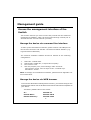
Management guide
Access the management interface of the
Switch
This section instructs you how to enter and proceed with the advanced
management capability, which can be accessed through console port or
Internet Browser over the network (in-band).
Manage the device via command line interface
To start-up the command line interface, please connect a PC COM port to
the RS-232 connector and activate a terminal emulation software (e.g.
HyperTerminal of Windows.)
The terminal emulation software should be started as the following
configuration:
1.
2.
3.
4.
Data rate: 115200 baud.
Data format: 8 data bits, 1 stop bit and no parity.
Flow control: none.
Click the property icon, select settings, make sure that:
“The Function, arrow, and ctrl keys act as”: Terminal keys.
“Emulation”: VT100.
Note: To manage via command line interface, please find the “Appendix” for
more information.
Manage the device via WEB browser
To access the Web-based management interface, you should configure the
management station with an IP address and subnet mask that compatible to
your switch.
The factory default value of the switch:
IP:
:
Subnet Mask:
:
Default Gateway:
:
192.168.2.1
255.255.255.0
192.168.2.254
12
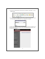
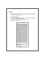
1. Running your Web Browser and enter the IP address “192.168.2.1” in the
Address field.
2. Key in the password 1234 (default value) to pass the authentication. Also,
you can initialize the Password in the configuration of System.
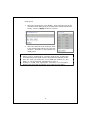
3. After authentication procedure, the following page shows up, and then you
may click the hyperlinks on the left side of each page to get access to each
management functions.
13
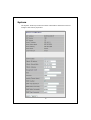
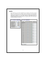
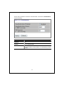
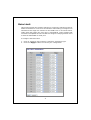
System
The System window provides the switch information and allows users to
configure the switch properties.
14
Items
MAC Address
S/W Version
H/W Version
Active IP Address
Active Subnet Mask
Active Gateway
DHCP Server
Lease Time Left
DHCP Enabled
Fallback IP Address
Fallback Subnet Mask
Fallback Gateway
Management VLAN
Name
Password
Inactivity Timeout
(secs)
SNMP enabled
SNMP Trap destination
SNMP Read Community
SNMP Write Community
SNMP Trap Community
Functions
The MAC address of this device..
The software version of this device.
The hardware version of this device.
The current IP address of the switch
The current Subnet Mask of the switch
The current Gateway of the switch
The IP Address of DHCP Server assign to client
for managing network automatically
The remaining lease time of IP Address that
DHCP Server assign to the client
Select it or not to obtain IP Address
automatically
Setup the IP address of the switch for fallback
Setup the Subnet Mask of the switch for
fallback
Setup the Gateway of the switch for fallback
The VLAN group that is allowed to access the
WEB-based management interface.
Defines the user-defined device name
The Login password. (the Default value is blank
or random value)
The time of automatic broken network
Select it or no to configure SNMP Network
Management, which allows network
administrators to monitor and configure this
device with SNMP software.
Specify a trap IP. A trap IP is the destination
port for sending trap information, which is
usually the IP address of network
administrators.
Fill in a name in the column, which is the
password for accessing MIB with read-only
authority.
Fill in a name in the column, which is the
password for accessing MIB with read-only
authority.
Configure the type of SNMP Trap Community
To save the configuration of the system, click “Apply” to save
Note:
After applying a new IP address, a new login page will be started
automatically. Please login again to proceed to other configurations.
15
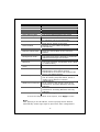
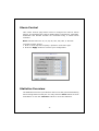
Port
This Port Configuration page shows the link status of each port and allows
users to configure speed, flow control for each port.
16
Items
Enable Jumbo Frames
Functions
Check the box to enable jumbo frames. You can
enable jumbo frames to support data packets up to
9600 bytes in size.
PERFECT_REACH/Power There are four options for power saving mode as the
Saving Mode
below: Full; Link Down; Link Up; Disable
Link
Shows the link status of each port. The column lights
green with the link speed while there is valid
connection on this port.
Mode
Select a speed for this port. “Auto Speed” enables
auto-negotiation. “Disable” stop the port from
functioning. You can also select 10/100 Half/Full
or 1000 Full
Flow Control
Mark the checkbox to enable the Flow control, or
unmark to disable.
Drop frames after
Enable or disable drop of frames when excessive
excessive collisions
collisions occur in half duplex mode
To save the configuration of the system, click “Apply” to save. You can also
click the “Refresh” button to see the latest status of each port.
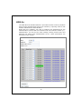
VLAN
VLAN divides the network members into groups to reduce packets collisions
and improve the network efficiency. The switch supports 802.1Q tag-based
VLAN. This page shows up VLAN Configuration List, and you can follow the
instructions to configure.
To add new VLAN groups,
1. Fill in a VLAN id from 2 to 4094 in the “VLAN ID” column.
Click ”Add” to come into the page of “VLAN Setup”
2. Select the ports for selected VLAN group.
3. Click the “Apply” button to execute.
In the VLAN Configuration List, you can Modify / Delete / Refresh a
17
VLAN group
1. Select the VLAN group, click “Modify”, then setup the Port as the
members of this VLAN group by clicking those marked checkboxes.
Finally, click the “Apply” button to execute.
2. Select the VLAN ID of the VLAN you want
in the VLAN Configuration List, then click
“Delete” / “Refresh” to clear/refresh this
VLAN group.
Note:
1. When a port is configured to a specific VLAN group, a PVID that
corresponding to the VLAN id will be assigned automatically to this
port. (Ex, when you make port 3 of a VLAN with VLAN id “2”, the
PVID “ 2 ” will be assigned automatically to port 3)
2. Settings in VLAN, Port aggregation, and Mirror are correlative.
Please make sure that the setting won’t influence each other.
18
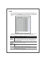
PVID
When the VLAN-enabled switch receives a tagged packet, the packet will be
sent to the port’s default VLAN according to the PVID (port VLAN ID) of the
receiving port. Click “Port Config”, the page of VLAN Per Port Configuration
pops up.
This page display when the switch is in Tag VLAN mode, the global setting of
the ports will affect all Tag VLANs. It contains the following fields:
Items
Port
VLAN
aware
Enabled
Ingress
Filtering
Enabled
Packet
Type
PVID
Functions
The switch Port Number 1~16/24
Set or show the VLAN awareness mode for the port. VLAN aware
ports will strip the VLAN tag from received frames and insert the
tag in transmitted frames (except PVID). VLAN unaware ports
will not strip the tag from received frames or insert the tag in
transmitted frames.
It determines how to process frames tagged for VLANs for which
the ingress port is not a member.
Tagged Only: block all un-tagged packets from accessing this
port.
All: all packets are allowed to access this port.
while receiving an untagged frame from the port, the switch will
assign a tag to the frame, using the PVID of the port as its VID.
Port VLAN ID(1~4094) or None
19
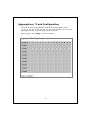
Aggregation/ Trunk Configuration
This page shows the aggregation groups and the aggregation mode.
To set up the Port trunk groups, put the ports number into the same
Aggregation group. There are eight groups to choose.
Don’t forget to click “Apply” to save the setting.
20
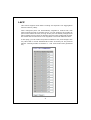
LACP
This switch supports both static trunking and dynamic Link Aggregation
Control Protocol (LACP).
LACP configured ports can automatically negotiate a trunked link with
LACP-configured ports on another device. You can configure any number of
ports on the switch as LACP, as long as they are not already configured as
part of a static trunk. If ports on another device are also configured as LACP,
the switch and the other device will negotiate a trunk link between them.
In this page, you can make the protocol enabled or not, and configure the
key value that is current administrative value of the Key for the protocol
partner. The key number is between 1 - 255. Auto means auto generated
key
21
RSTP
Rapid Spanning Tree Protocol (IEEE 802.1w) supports connections to RSTP
nodes by monitoring the incoming protocol messages and dynamically
adjusting the type of protocol messages the RSTP node transmits If RSTP is
using 802.1D BPDUs on a port and receives an RSTP BPDU after the
migration delay expires, RSTP restarts the migration delay timer and begins
using RSTP BPDUs on that port.
22
Items
Functions
System Priority Used in selecting the root device, root port, and
designated port. The device with the highest priority
becomes the STA root device.
Hello Time
Interval (in seconds) at which the root device transmits a
configuration message
Max Age
The maximum time (in seconds) a device can wait without
receiving a configuration message before attempting to
reconfigure. All device ports (except for designated ports)
should receive configuration messages at regular
intervals.
Forward Delay The maximum time (in seconds) the root device will wait
before changing states (i.e., discarding to learning to
forwarding). This delay is required because every device
must receive information about topology changes before
it starts to forward frames.
Force Version There are two options as below: Normal, Compatible.
Protocol
Enable or disable the RSTP protocol on ports
Enabled
Edge
Expect the port to be an edge port (an end station) or a
link to another STP device.
Path Cost
Set the RSTP path cost on ports. Auto means auto
generated path cost
23
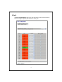
802.1x
The IEEE 802.1X standard defines a port-based access control procedure
that prevents unauthorized access to a network by requiring users to first
submit credentials for authentication.
When 802.1X is enabled, you need to configure the parameters for the
authentication process that runs between the client and the switch (i.e.,
authenticator), as well as the client identity lookup process that runs
between the switch and authentication server. These parameters are
described in this section.
24
Items
Functions
Indicates if authentication is enabled or disabled on the
port. (Default: Disabled)
RADIUS IP
Set the RADIUS server IP Address
RADIUS UDP Port Set the RADIUS server network port
RADIUS Secret
Set the RADIUS encryption key
Admin State
Sets the authentication mode to one of the following
options
Auto – Requires a dot1x-aware client to be authorized by
the authentication server. Clients that are not
dot1x-aware will be denied access.
Force-Authorized – Forces the port to grant access to
all clients, either dot1x-aware or otherwise. (This is the
default setting.)
Force-Unauthorized – Forces the port to deny access to
all clients, either dot1x-aware or otherwise.
Port State
Display the current status of authentication.
Re-authenticate
Sets the client to be re-authenticated after the interval
specified by the Re-authentication Period.
Re-authenticate can be used to detect if a new device is
plugged into a switch port.
Force Reinitialize Set this 802.1x configuration to initialize by compulsion.
Statistics
Display statistics for dot1x protocol exchanges for any
port.
Mode
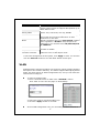
Click “Statistics”, the following page of detailed info for each port pops up
25
Some other parameters would be indicated after click button “Parameters”
as the following:
Items
Reauthentication
Enabled
Reauthentication
Period
EAP timeout
Functions
Set Reauthentication to be enabled or disabled on the
port.
Set the time period after which a connected client must
be re-authenticated.
Set the time that an interface on the switch waits during
an authentication session before re-transmitting an EAP
packet.
26
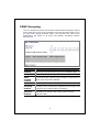
IGMP Snooping
You can configure the switch to forward multicast traffic intelligently. Based
on the IGMP query and report messages, the switch forwards traffic only to
the ports that request multicast traffic. This prevents the switch from
broadcasting the traffic to all ports and possibly disrupting network
performance.
Items
IGMP
Enabled
Router Ports
Unregistered
IPMC
Flooding
enabled
VLAN ID
IGMP
Snooping
Enabled
IGMP
Querying
Enabled
Functions
When enabled, the switch will monitor network traffic to
determine which hosts want to receive multicast traffic.
Set or show IGMP administrative router ports.
Set or show forwarding mode for unregistered (not-joined)
IP multicast traffic. Will flood when enabled, and forward to
router-ports only when disabled
ID of configured VLAN (1-4094).
When enabled, it simply monitors the IGMP packets passing
through it, picks out the group registration information, and
configures the multicast filters accordingly.
When enabled, the switch can serve as the Querier, which is
responsible for asking hosts if they want to receive
multicast traffic.
27
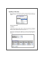
Quality of Service
QoS enhances the communication quality by giving different precedence to
classified packets. This switch provides QoS Disabled, 802.1P and DSCP
modes:
Select the QoS Mode
(1) 802.1p
In IEEE 802.1p priority mode, when a switch port receives an untagged
frame (a frame without priority tag), the port's default priority tag will be
inserted into the frame before any other process.
This page is revealed when the “IEEE 802.1 p” mode is configured as shown
below, Click on the drop list to specify priority levels, then click “Apply” to
execute.
28
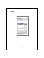
(2) DSCP
This page is revealed when the “DSCP” mode is configured as shown below.
The DSCP mode QoS gives packet priority by the types of the incoming
packets. DSCP value’s range is between 0 and 63. Give the priorities as
normal/high/low for each precedence types, then click “Apply” to execute.
29
Mirror
The Mirror function copies all the packets that are transmitted by the source
port to the destination port. It allows administrators to analyze and monitor
the traffic of the monitored ports.
Mirror Configuration:
1. Select those ports that are going to be monitored by marking the
checkboxes in “Monitor Source” column.
2. Click the drop list in “Mirror Port” column. Select a port as the
administration port for monitoring those source ports.
3. Click “Apply” to activate.
30
Rate Limit
This function allows the network manager to control the maximum rate for
traffic transmitted or received on an interface. Rate limiting is configured on
interfaces at the edge of a network to limit traffic into or out of the switch.
Traffic that falls within the rate limit is transmitted, while packets that
exceed the acceptable amount of traffic are dropped. This page allows users
to limit the bandwidth for each port.
To configure the Rate Limit:
1. Click on each drop list to specify a speed for each frame type.
2. Click the “Apply” button to execute your configuration.
31
Storm Control
This “storm Control” page allows users to configure the rules for Storm
Control. The allowed frame rates for ICMP frames, learn frames, multicasts,
broadcasts and flooded unicasts are controlled using a central storm
controller.
Rate: Allowed values are 1k, 2k, 4k, 8k, 16k, 32k, 64k, or No limit.
To perform storm control:
1. Click on each drop list to specify a speed for each frame type.
2. Click the “Apply” button to execute your configuration.
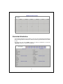
Statistics Overview
The Statistics Overview is provided for users to see the general transmitting
and receiving status of each port. You may click the “Clear” button to clean
all statistics or click the “Refresh” button to renew the statistics.
32
Detailed Statistics
The Detailed Statistics is provided for users to see the detailed transmitting
and receiving status of each port. Please click the hyperlinks above to select
a port.
You may also click the “Clear” button to clean all statistics or click the
“Refresh” button to renew the statistics.
33
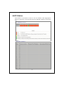
LACP Status
LACP Status is provided for users to see the detailed LACP Aggregation
status of each port. You may also click the “Refresh” button to renew the
info.
34
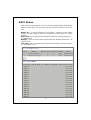
RSTP Status
RSTP Status is provided for users to see the detailed RSTP VLAN Bridge
status for each port. You may also click the “Refresh” button to renew the
info.
Bridge ID – A unique identifier for this bridge, consisting of the bridge
priority and MAC address (where the address is taken from the switch
system).
Hello time - Set or show the RSTP System Hello time. Number between 1 10 (default is 2)
Maxage - Set or show the RSTP System Max Age. Number between 6 - 40
(default is 20)
Fwd delay- Set or show the RSTP System Forward delay. Number between
4 - 30 (default is 15)
35
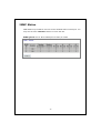
IGMP Status
IGMP Status is provided for users to see the detailed status of each port. You
may also click the “Refresh” button to renew the info.
IGMP Querier: Set or Show IGMP querier state per VLAN.
36
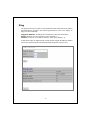
Ping
The ping function is to test the connectedness of the link between the switch
and destination. Configure the following parameters, then click “Apply” to
ping the connectedness.
Target IP Address: Indicates the IP Address of the test destination.
Count: Number of echo requests to send (default: 1).
Timeout: Timeout in seconds to wait for each reply (default: 2).
In the below table, it displays ping results contain Target IP Address /Status
/Received replies/Request timeouts/Average Response Time(in ms).
37
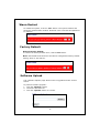
Warm Restart
To restart the system, click the “Yes” button. The system restarts and
shows the authentication window. Please fill in the username and password
to continue.
Factory Default
Restore Factory Default:
To restore the factory default value, click the Yes button.
Note: The IP address of the device will also be configured as factory-default
setting, which is 192.168.2.1.
Software Upload
This “Software Upload” page allows users to upgrade firmware for this
switch.
To
1.
2.
3.
perform firmware upgrade:
Click the “Browse” button
Locate the firmware file
Click the “Upload” button to execute.
38
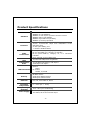
Product Specifications
Standard
IEEE802.3 10 BASE-T
IEEE802.3u 100 BASE-TX
IEEE802.3x full-duplex operation and flow control
IEEE802.3ab/z 1000 BASE-T
IEEE802.1Q VLAN interoperability
IEEE802.1p Priority Operation
Interface
16/24* 10/100/1000 Mbps
switching ports
4* SFP (mini-GBIC) port
1 * Restore Default Button
Cable
Connections
auto
10/100/1000 Mbps Auto-negotiation
Transmission
Mode
10/100 Mbps Full-duplex, Half-duplex
1000 Mbps Full-duplex
System
Power
RJ-45 Port
1000M, 10/100M
Memory
8K MAC entries
500K Bytes Buffer Memory
9600 Bytes Jumbo Frame
Emission
FCC, CE, VCCI Class A, RoHS
Operating
Temperature
Operating
Humidity
Power Supply
RJ-45
RJ-45 (10 BASE-T): Category 3,4,5 UTP/STP
RJ-45 (100 BASE-TX): Category 5 UTP/STP
RJ-45 (1000 BASE-T): Category 5e, 6 or enhanced
UTP/STP
Fiber: depend on mini-GBIC types
Network Data
Rate
LED Indications
MDI/MDI-X
0° ~ 40°C (32° ~ 104°F)
10% - 90% (non-condensing)
Internal power supply
100-240V/ 50-60 Hz universal input
39
Appendix- Command Line Interface
Start-up and Terminal configuration
To start-up the command line interface, please connect a PC COM port to
the RS-232 connector and activate a terminal emulation software (e.g.
HyperTerminal of Windows).
The terminal emulation software should be started as the following
configuration:
1.
2.
3.
4.
Data rate: 115200 baud.
Data format: 8 data bits, 1 stop bit and no parity.
Flow control: none.
Click the property icon, select settings, make sure that:
“The Function, arrow, and ctrl keys act as”: Terminal keys.
“Emulation”: VT 100.
Login/Logout Procedures
To get access to the CLI, you will have to Key in the password to pass the
authentication. The factory default value of Password is blank, or other
random value.
Note: We recommend users to configure a new password to prevent
unauthorized users from accessing to the device.
40
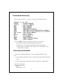
Command Hierarchy
After logging in, press ? + <enter> to show the 9 command groups.
Press ? or help to get help. The help depends on the context:
- At top level, a list of command groups will be shown.
- At group level, a list of the command syntaxes will be shown.
- If given after a command, the syntax and a description of the
command will be shown.
Entering Commands
To give any command, please key in your command and press enter.
EX,
1. Type “System” and press <enter> to get access to the system command
group.
2. Type “Configuration” and press <enter> to perform “configuration”
System>configuration
System Configuration:
Name:
S/W Version: 1.00
41
CVS Tag: sw_8051_2_34d
Compile Date: Sep 21 2009 11:26:36
H/W Version: 1.0
MAC address: 00-08-54-00-00-31
SNMP: enabled
Trap IP: 0.0.0.0
Readcommunity: public
Writecommunity: private
Trapcommunity: public
You can type “up” and press <enter> to go back to upper level.
Command Description
The following session introduces the command structure of the command
line interface.
Command groups:
System
- System commands
Console
- Console commands
Port
- Port commands
MAC
- MAC commands
VLAN
- VLAN commands
Aggr
- Aggregation commands
LACP
- IEEE 802.3ad Link Aggregation commands
RSTP
- IEEE 802.1w Rapid Spanning Tree commands
User Group - User Group commands
QoS
- QoS commands
Mirror
- Mirror commands
IP
- IP commands
Dot1x
- Dot1x commands
IGMP
- IGMP Snooping commands
Debug
- Debug commands
System Commands
System
System
System
System
System
System
System
System
System
System
Configuration [all]
Restore Default [keepIP]
Name [<name>]
Reboot
SNMP [enable|disable]
Trap [<IP Address>]
Readcommunity [<community string>]
Writecommunity [<community string>]
Trapcommunity [<community string>]
Power Saving [full|up|down|disable]
42
System Configuration [all]
Description:
Show system name, software version, hardware version and management
MAC address. Optionally show the full configuration
[all]: Show the total switch configuration (default: System configuration
only)
System Restore Default [keepIP]
Description:
Restore factory default configuration.
[keepIP]: Preserve IP configuration (default: Not preserved).
System Name [<name>]
Description:
Set or show the system name.
[<name>]: String of up to 16 characters (default: Show system name).
System Reboot
Description:
Reboot the switch.
SNMP [enable|disable]
Description:
Activate or deactivate the SNMP.
[enable|disable]: Enable/disable SNMP (default: Show SNMP mode).
Trap [<IP Address>]
Description:
Set or show SNMP traps destination.
<IP Address>: IP address to send traps to. (default: Show trap
configuration)
43
Readcommunity [<community string>]
Description:
Set or show SNMP read community string.
[<community string>]: New community string. (default: Show current
value).
Writecommunity [<community string>]
Description:
Set or show SNMP write community string.
[<community string>]: New community string. (default: Show current
value).
Trapcommunity [<community string>]
Description:
Set or show SNMP trap community string.
[<community string>]: New community string. (default: Show current
value).
Sytem Power Saving [full|up|down|disable]
Description:
Configure mode of power saving.
[full|up|down|disable]:
full
: Power saving at both link-up and link-down.
up
: Power saving at link-up only.
down
: Power saving at link-down only.
disable : No power saving
44
Console Commands
Commands at Console level:
Console Configuration
Console Password [<password>]
Console Timeout [<timeout>]
Console Prompt [<prompt string>]
Console Configuration
Description:
Show configured console password and timeout.
Console Password [<password>]
Description:
Set or show the console password. The empty string ("") disables the
password check.
[<password>]: Password string of up to 16 characters.
Console Timeout [<timeout>]
Description:
Set or show the console inactivity timeout in seconds. The value zero
disables timeout.
[<timeout>]: Timeout value in seconds, 0,60-10000.
Console Prompt [<prompt_string>]
Description:
Set or show the console prompt string.
[<prompt_string>]: Command prompt string of up to 10 characters.
45
Port Commands
Commands at Port level:
Port Configuration [<portlist>]
Port Mode [<portlist>] [<mode>]
Port Flow Control [<portlist>] [enable|disable]
Port State [<portlist>] [enable|disable]
Port MaxFrame [<portlist>] [<framesize>|reset]
Port Statistics [<portlist>] [clear]
Port Excessive Collisions Drop [enable|disable]-----#Note: If you want to change maxframe bigger than 1518,
the [Flow Control] should be enabled!
Port Configuration [<portlist>]
Description:
Show the configured and current speed, duplex mode, flow control mode and
state for the port.
[<portlist>]: Port list (Default: All ports).
Port Mode [<portlist>] [<mode>]
Description:
Set or show the speed and duplex mode for the port.
[<portlist>]: Port list (Default: All ports).
[<mode>]
: Port speed and duplex mode (Default: Show configured and
current mode).
10hdx : 10 Mbit/s, half duplex.
10fdx : 10 Mbit/s, full duplex.
100hdx : 100 Mbit/s, half duplex.
100fdx : 100 Mbit/s, full duplex.
1000fdx: 1 Gbit/s, full duplex.
auto : Auto negotiation of speed and duplex.
Port Flow Control [<portlist>] [enable|disable]
Description:
Set or show flow control mode for the port.
[<portlist>]
: Port list (default: All ports).
[enable|disable]: Enable/disable flow control (default: Show flow control
mode).
46
Port State [<portlist>] [enable/disable]
Description:
Set or show the state for the port.
[<portlist>]
: Port list (default: All ports).
[enable|disable]: Enable or disable port state (default: Show state).
Port MaxFrame [<portlist>] [<framesize>|reset]
Description:
Set or show the maximum frame size in bytes (including FCS) for frames
received on the port. Tagged frames are allowed to be 4 bytes longer than
the maximum frame size. Use the reset option to return to default setting.
[<portlist>]
: Port list (default: All ports).
[<framesize>|reset]: Maximum frame size [1518-9600] or reset to 1518
bytes (default: Show maximum frame size).
Port Statistics [<portlist>] [clear]
Description:
Show or clear statistics for the port.
[<portlist>]: Port list (default: All ports).
[clear]
: Clear port statistics (default: Show statistics).
Port Excessive Collisions Drop [enable|disable]
Description:
Enable or disable drop of frames when excessive collisions occur in half
duplex mode.
[enable|disable]: Enable/disable frame drop (default: Show Excessive
Collisions Drop mode).
47
MAC Commands
Commands at MAC level:
MAC Configuration
MAC Add <macaddress> <portlist>|none [<vid>]
MAC Delete <macaddress> [<vid>]
MAC Lookup <macaddress> [<vid>]
MAC Table <vidlist>
MAC Flush
MAC Agetime [<agetime>]
MAC Configuration
Description:
Show the permanently stored MAC table and the MAC ageing timer.
MAC Add <macaddress> <portlist>|none [<vid>]
Description:
Add permanent MAC address and VLAN ID on ports.
<macaddress>: MAC address, 12 digit hex string, optionally separated with
dashes or colons (e.g. 010203ABCDEF or 01-02-03-AB-CD-EF or
01:02:03:AB:CD:EF).
<portlist> : Port list. Use "none" to specify no ports.
[<vid>]
: VLAN ID, 1-4094 (default: 1).
MAC Delete <macaddress> [<vid>]
Description:
Delete MAC address and VLAN ID.
<macaddress>: MAC address, 12 digit hex string, optionally separated with
dashes or colons (e.g. 010203ABCDEF or 01-02-03-AB-CD-EF or
01:02:03:AB:CD:EF).
[<vid>]
: VLAN ID (default: All).
MAC Lookup <macaddress> [<vid>]
Description:
Lookup MAC address and VLAN ID.
<macaddress>: MAC address, 12 digit hex string, optionally separated with
48
[<vid>]
dashes or colons (e.g. 010203ABCDEF or 01-02-03-AB-CD-EF or
01:02:03:AB:CD:EF).
: VLAN ID, 1-4094 (default: 1).
MAC table <vidlist>
Description:
Show the MAC address table for VLAN ID list.
<vidlist>
: VLAN ID list.
MAC Flush
Description:
Removes non-locked entries from the switch MAC table.
MAC Agetime [<agetime>]
Description:
Set or show the MAC age timer in seconds. The value zero disables ageing.
[<agetime>]: Age timer in seconds, 0 or 10-65535 (default: Show timer).
49
VLAN Commands
Commands at VLAN level:
VLAN Configuration [<portlist>]
VLAN Add <vidlist> [<portlist>]
VLAN Delete <vidlist>
VLAN Lookup <vidlist>
VLAN Aware [<portlist>] [enable|disable]
VLAN PVID [<portlist>] [<vid>|none]
VLAN Frame Type [<portlist>] [all|tagged]
VLAN Ingress Filtering [<portlist>] [enable|disable]
VLAN Configuration [<portlist>]
Description:
Show the VLAN aware mode, port VLAN ID and accepted frame type for the
port and the permanently stored VLAN table.
[<portlist>]: Port list (default: All ports).
VLAN Add <vidlist> [<portlist>]
Description:
Add VLAN entry and include ports in member set.
<vidlist> : VLAN ID list.
[<portlist>]: Port list (default: All ports).
VLAN Delete <vidlist>
Description:
Delete VLAN entry (all ports excluded from member set).
<vidlist> : VLAN ID list.
VLAN Lookup <vidlist>
Description:
Lookup VLAN entry and show port list.
<vidlist> : VLAN ID list.
50
VLAN Aware [<portlist>] [enable|disable]
Description:
Set or show the VLAN awareness mode for the port. VLAN aware ports will
strip the VLAN tag from received frames and insert the tag in transmitted
frames (except PVID). VLAN unaware ports will not strip the tag from
received frames or insert the tag in transmitted frames.
[<portlist>]: Port list (default: All ports).
[enable|disable]: Enable/disable VLAN awareness (default: Show
awareness).
VLAN PVID [<portlist>] [<vid>|none]
Description:
Set or show the port VLAN ID. Untagged frames received on the port will be
classified to this VLAN ID. Frames classified to this VLAN ID will be sent
untagged on the port.
[<portlist>]: Port list (default: All ports).
[<vid>|none]: Port VLAN ID, 1-4094 (default: Show PVID).
The 'none' option can be used for trunk links.
VLAN Frame Type [<portlist>] [all|tagged]
Description:
Set or show the accepted frame type for the port.
[<portlist>]: Port list (default: All ports).
[all|tagged]: Accept all or only tagged (default: Show frame type).
VLAN Ingress Filtering [<portlist>] [enable|disable]
Description:
Set or show VLAN ingress filtering for the port.
[<portlist>]: Port list (default: All ports).
[enable|disable]: Enable or disable VLAN ingress filtering
(default: Show current setting).
51
Aggregation Commands
Commands at Aggr level:
Aggr Configuration
Aggr Add <portlist>
Aggr Delete <portlist>
Aggr Lookup <portlist>
Aggr Mode [smac|dmac|xor]
Aggr Configuration
Description:
Shows the aggregation groups and the aggregation mode.
Aggr Add <portlist>
Description:
Add link aggregation group including ports.
<portlist>: Aggregation port list.
Aggr Delete <portlist>
Description:
Delete link aggregation group.
<portlist>: Port list. Aggregations including any of the ports will be deleted.
Aggr Lookup <portlist>
Description:
Lookup and display link aggregation group.
<portlist>: Port list. Aggregations including any of the ports will be shown.
Aggr Mode [smac|dmac|xor]
Description:
Set or show link aggregation traffic distribution mode.
[smac|dmac|xor]: Aggregation mode, SMAC, DMAC or XOR (default: Show
mode).
52
LACP Commands
Commands at LACP level:
LACP Configuration [<portlist>]
LACP Mode [<portlist>] [enable|disable]
LACP Key [<portlist>] [<key>|auto]
LACP Status
LACP Statistics
LACP Configuration [<portlist>]
Description:
Show LACP configuration.
[<portlist>]: Port list (Default: All ports).
LACP Mode [<portlist>] [enable|disable]
Description:
Enable or disable the LACP protocol on ports <portlist>.
[<portlist>]: Port list (Default: All ports).
[enable|disable]: Enable or disable.
LACP Key [<portlist>] [<key>|auto]
Description:
Set the LACP key on ports <portlist>.
[<portlist>]: Port list (Default: All ports).
[<key>]: Number between 1 - 255. Auto means auto generated key
LACP Status
Description:
Show LACP group and port states.
LACP Statistics
Description:
Show LACP protocol port statistics.
53
RSTP Commands
Commands at RSTP level:
RSTP Configuration [<portlist>]
RSTP sysprio [<sysprio>]
RSTP hellotime [<secs>]
RSTP maxage [<hops>]
RSTP fwddelay [<secs>]
RSTP version [normal|compat]
RSTP Mode [<portlist>] [enable|disable]
RSTP Aggr [enable|disable]
RSTP Edge [<portlist>] [enable|disable]
RSTP Pathcost [<portlist>] [<pathcost>|auto]
RSTP mcheck <portlist>
RSTP Status
RSTP Statistics
RSTP Configuration [<portlist>]
Description:
Show RSTP configuration.
[<portlist>]: Port list (Default: All ports).
RSTP sysprio [<sysprio>]
Description:
Set or show the RSTP System Priority.
[<sysprio>]: Number between 0 - 61440 in increments of 4096
This provides for 16 distinct values: 0, 4096, 8192, 12288, 16384, 20480,
24576, 28672, 32768, 36864, 40960, 45056, 49152, 53248, 57344 and
61440.
RSTP hellotime [<secs>]
Description:
Set or show the RSTP System Hello time.
[<secs>]: Number between 1 - 10 (default is 2)
54
RSTP maxage [<hops>]
Description:
Set or show the RSTP System Max Age.
[<hops>]: Number between 6 - 40 (default is 20)
RSTP fwddelay [<secs>]
Description:
Set or show the RSTP System Forward delay.
[<secs>]: Number between 4 - 30 (default is 15)
RSTP version [normal|compat]
Description:
Set or show the RSTP protocol version to use.
[<version>]: normal - use RSTP, compat - compatible with old STP
RSTP Mode [<portlist>] [enable|disable]
Description:
Enable or disable the RSTP protocol on ports <portlist>.
[<portlist>]: Port list (Default: All ports).
[enable|disable]: Enable or disable.
RSTP aggr [enable|disable]
Description:
Enable or disable the RSTP protocol on aggregated links.
[enable|disable]: Enable or disable.
RSTP edge [enable|disable]
Description:
Expect the port to be an edge port (an end station) or a link to another STP
device.
[enable|disable]: End-station or bridge.
55
RSTP pathcost [<portlist>] [<pathcost>|auto]
Description:
Set the RSTP pathcost on ports <portlist>.
[<portlist>]: Port list (Default: All ports).
[<pathcost>]: Number between 1 - 200000000. Auto means auto generated
pathcost
RSTP mcheck <portlist>
Description:
Force a recheck of the RSTP protocol on the ports in <portlist>.
<portlist>: List of ports.
RSTP Status
Description:
Show RSTP bridge instances and port states.
RSTP Statistics
Description:
Show RSTP bridge instance and port statistics.
56
User Group Commands
Commands at User Group level:
User Group Configuration
User Group Add <grouplist> [<portlist>]
User Group Delete <grouplist>
User Group Lookup <grouplist>
User Group Configuration
Description:
Show the user groups.
User Group Add <grouplist> [<portlist>]
Description:
Add user group entry including the ports.
<grouplist> : User group ID list.
[<portlist>]: Port list (default: All ports).
User Group Delete <grouplist>
Description:
Delete user group entry.
<grouplist>: User group ID list.
User Group Lookup <grouplist>
Description:
Lookup user group entry and show port members.
<grouplist>: User group ID list.
57
QoS Commands
Commands at QoS level:
QoS Configuration [<portlist>]
QoS Mode [<portlist>] [tag|port|diffserv]
QoS Default [<portlist>] [<class>]
QoS Tagprio [<portlist>] [<tagpriolist>] [<class>]
QoS DiffServ [<dscpno>] [<class>]
QoS Userprio [<portlist>] [<tagprio>]
QoS Shaper [<portlist>] [enable|disable] [<rate>]
QoS Policer [<portlist>] [enable|disable] [<rate>]
QoS Storm Control [<traffic type>] [enable|disable] [<rate>]
<class> range: low|normal|medium|high
<traffic type>: ICMP|Learn|Broadcast|Multicast|Flood Unicast
QoS Configuration [<portlist>]
Description:
Show the configured QoS mode, VLAN user priority mapping, default class,
default VLAN user priority and DSCP mapping for the port.
[<portlist>]: Port list (default: All ports).
QoS Mode [<portlist>] [tag|port|diffserv]
Description:
Set or show the QoS mode for the port.
[<portlist>]
: Port list (default: All ports).
[tag|port|diffserv]: Enable tag, port or IP differentiated services
class of service for the port (default: Show mode).
QoS Default [<portlist>] [<class>]
Description:
Set or show the default class. In tag mode, the default class is used for
untagged frames. In port mode, the default class is used as the port priority.
In diffserv mode, the default class is used for non-IP frames.
[<portlist>]: Port list (default: All ports).
[<class>] : Internal class of service (default: Show default class).
58
QoS Tagprio [<portlist>] [<tagpriolist>] [<class>]
Description:
Set or show the VLAN user priority mapping.
[<portlist>] : Port list (default: All ports).
[<tagpriolist>]: VLAN user priority list, 0-7 (default: All user priorities).
[<class>]
: Internal class of service (default: Show class).
QoS DiffServ [<dscpno>] [<class>]
Description:
Set or show the IP Differentiated Services mapping.
[<dscpno>]: IP DSCP number, 0-63 (default: All DSCP values).
[<class>] : Internal class of service (default: Show class).
QoS Userprio [<portlist>] [<tagprio>]
Description:
Set or show the default VLAN user priority for received untagged frames.
[<portlist>]: Port list (default: All ports).
[<tagprio>] : VLAN tag user priority, 0-7 (default: Show user priority).
QoS Shaper [<portlist>] [enable|disable] [<rate>]
Description:
Set or show the shaper configuration.
[<portlist>]
[enable|disable]
[<rate>]
: Port list (default: All ports).
: Enable or disable shaper.
: Disable or set leaky bucket rate in Kbit/s
[0k,128k,256k,384k,512k,640k,768k,896k,1024k,1152k,1280k
1408k,1536k,1664k,1792k,1920k,2048k,2176k,2304k,2432k
2560k,2688k,2816k,2944k,3072k,3200k,3328k,3456k,3584k
3712k,3840k,3968k]
(default: Show shaper rate 0k is disable).
QoS Policer [<portlist>] [disable | <rate>]
Description:
Set or show the policer configuration.
59
[<portlist>]
[enable|disable]
[<rate>]
: Port list (default: All ports).
: Enable or disable policer.
: Disable or set leaky bucket rate in Kbit/s
[0k,128k,256k,384k,512k,640k,768k,896k,1024k,1152k,1280k
1408k,1536k,1664k,1792k,1920k,2048k,2176k,2304k,2432k
2560k,2688k,2816k,2944k,3072k,3200k,3328k,3456k,3584k
3712k,3840k,3968k]
(default: Show policer rate 0k is disable ).
QoS Storm Control [<traffic type>] [enable|disable] [<rate>]
Description:
Set or show the storm control configuration. The allowed frame rates for
ICMP frames, learn frames, multicasts, broadcasts and flooded unicasts are
controlled using a central storm controller.
[<traffic type>]
[enable|disable]
[<rate>]
: Storm controller to set. Can be one of:
[ICMP|Learn|Broadcast|Multicast|Flood Unicast]
(default: Show all).
: Enable or disable specified storm controller.
: Frame rate in kiloframes
Allowed values are 1k, 2k, 4k, 8k, 16k, 32k, 64k,
60
Mirror Commands
Commands at Mirror level:
Mirror Configuration
Mirror Port [<port>]
Mirror Source [<portlist>] [enable|disable]
Mirror Configuration
Description:
Show the mirror destination port and mirror mode for source ports.
Mirror Port [<port>]
Description:
Set or show the mirror destination port.
[<port>]: Mirror destination port (default: Show mirror port).
Mirror Source [<portlist>] [enable|disable]
Description:
Set or show the source port mirror mode.
[<portlist>]
: Source port list (default: All ports).
[enable|disable]: Enable/disable mirroring of frames received on
port (default: Show mirror mode).
61
IP Commands
Commands at IP level:
IP Configuration
IP Status
IP Setup [<ipaddress> [<ipmask> [<ipgateway>]]] [<vid>]
IP Mode [enable|disable]
IP Ping [-n <count>] [-w <timeout>] <ipaddress>
IP Arp
IP Dhcp [enable|disable]
IP Configuration
Description:
Show IP configured IP address, mask, gateway, VLAN ID and mode.
IP Status
Description:
Show current IP status.
IP Setup [<ipaddress> [<ipmask> [<ipgateway>]]] [<vid>]
Description:
Setup or show IP configuration.
[<ipaddress>]: IP address. (default: Show IP configuration)
[<ipmask>] : IP subnet mask (default: Subnet mask for address class).
[<ipgateway>]: Default IP gateway, (default: 0.0.0.0).
[<vid>]
: VLAN ID, 1-4094 (default: 1).
IP Mode [enable|disable]
Description:
Activate or deactivate the IP configuration.
[enable|disable]: Enable/disable IP (default: Show IP mode).
IP Ping [-n <count>][-w <timeout>] <ipaddress>
Description:
Ping the specified IP address.
[-n <count>]:
Number of echo requests to send (default: 1).
[-w <timeout>]: Timeout in seconds to wait for each reply (default: 2).
62
IP Arp
Description:
Show the content of the ARP table.
IP DHCP [enable|disable]
Description:
Activate or deactivate the DHCP protocol.
[enable|disable]: Enable/disable DHCP (default: Show DHCP mode).
63
Dot1x Commands
Commands at Dot1x level:
Dot1x Configuration
Dot1x Mode [enable|disable]
Dot1x State [<portlist>] [Auto|ForceAuthorized|ForceUnauthorized]
Dot1x Server [<IP Address>]
Dot1x UDP Port [<value>]
Dot1x Secret [<Shared Secret>]
Dot1x Statistics [<portlist>]
Dot1x Reauthenticate [<portlist>] [now]
Dot1x Parameters [<parameter>] [<value>]
Dot1x Configuration
Description:
Show current 802.1X configuration.
Dot1x Mode [enable|disable]
Description:
Enable or disable 802.1X process for the switch.
[enable|disable]: new mode (default: Show current configuration).
Dot1x State [<portlist>]
[Auto|ForceAuthorized|ForceUnauthorized]
Description:
Set or show the 802.1X state for the port.
[<portlist>]
: Port list (default: All ports).
[Auto|ForceAuthorized|ForceUnauthorized]: Set 802.1X state for the ports.
(default: Show mode).
Dot1x Server [<IP Address>]
Description:
Set or show RADIUS server IP address.
[<IP Address>]: IP address of external RADIUS server.
(default: Show current configuration)
64
Dot1x UDP Port [<value>]
Description:
Set up UDP Port for the external RADIUS server.
[<value>]: The UDP port the RADIUS server listens to
(default: Show current configuration).
Dot1x Secret [<Shared Secret>]
Description:
Set or show the secret shared with the RADIUS server.
[<Shared Secret>]: Shared secret shared with external RADIUS server.
(default: Show current configuration)
Dot1x Statistics [<portlist>]
Description:
Show 802.1X statistics for the port.
[<portlist>]: Port list (default: All ports).
Dot1x Reauthenticate [<portlist>] [now]
Description:
Refresh (restart) 802.1X authentication process for the port
by setting reAuthenticate TRUE.
[<portlist>]: Port list (default: All ports).
[now]: if specified, force re-authentication immediately.
Dot1x Parameters [<parameter>] [<value>]
Description:
Set up advanced 802.1X parameters.
[<parameter>]: Parameter to change.
[<value>]: New value for the given parameter.
65
IGMP Commands
Commands at IGMP level:
IGMP Configuration
IGMP Status
IGMP Groups <vidlist>
IGMP Mode [enable|disable]
IGMP State <vidlist> [enable|disable]
IGMP Querier <vidlist> [enable|disable]
IGMP Router ports [<portlist>] [enable|disable]
IGMP Unregistered Flood [enable|disable]
Ratelimit Configuration
IGMP Configuration
Description:
Show the IGMP configuration.
IGMP Status
Description:
Show the IGMP operational status and statistics.
IGMP Groups <vidlist>
Description:
Show IGMP groups for given VLANs.
IGMP Mode [enable|disable]
Description:
Set or show global IGMP mode.
(default: Show current mode)
IGMP State <vidlist> [enable|disable]
Description:
Set or Show IGMP state per VLAN.
(default: Show IGMP state)
IGMP Querier <vidlist> [enable|disable]
Description:
Set or Show IGMP querier state per VLAN.
(default: Show IGMP querier state)
66
IGMP Router ports [<portlist>] [enable|disable]
Description:
Set or show IGMP administrative router ports.
(default: Show current router ports)
IGMP Unregistered Flood [enable|disable]
Description:
Set or show forwarding mode for unregistered (not-joined) IP multicast
traffic. Will flood when enabled, and forward to router-ports only when
disabled
(default: Show current mode)
Debug Commands
Commands at Debug level:
Debug Read Register <block> <subblock> <address>
Debug Read Register <block> <subblock> <address>
Description:
Read register address.
<block>
: Block identifier, 0-7 or 0x0-0x7.
<subblock> : Sub block identifier: 0-15 or 0x0-0xf.
<address> : Register address within block, 0-255 or 0x00-0xff.
67