1
!
!
!
!
!
!
AQUAPRO!OWNER’S!MANUAL!
!
4438!Muhlhauser!Road!!
Suite!600!
Hamilton,!OH!45011!
877F278F2797!
1-877-278-2797
TABLE OF CONTENTS
HOW A HEAT PUMP WORKS ------------------------------------------ 1
SAFETY INFORMATION------------------------------------------------ 2
QUICK START & STOP ------------------------------------------------- 4
HEATER CONTROLS --------------------------------------------------- 6
Control Panel Layout -----------------------------------------------6
Buttons, Lights, and Display --------------------------------------6
Operational & Programming Codes --------------------------------7
Owner-Level Programming (complete) --------------------------- 8
MAINTENANCE AND GENERAL OPERATION --------------------------12
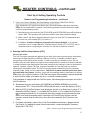
General Maintenance-----------------------------------------------12
Safety During Cleaning Operations ------------------------------- 12
Maintaining Proper Water Flow ------------------------------------ 13
Controlling Water Chemistry --------------------------------------13
Controlling Irrigation and Storm Water Run Off ------------------ 14
Maintaining Clearances Around Heater --------------------------- 14
(Continued on Next Page)
3
TABLE OF CONTENTS
(CONTINUED)
MAINTENANCE AND GENERAL OPERATION...CONTINUED:
Heating Tips--------------------------------------------------------15
- Heating in Cooler Weather --------------------------------------15
Pool/Spa Blankets-----------------------------------------------15
Pool & Spa Combination Heating ------------------------------- 15
Spa Set-Back Option ------------------------------------------- 15
Calculating Initial Heating Time -----------------------------------16
Seasonal Use & Shut Down ---------------------------------------- 17
- (Use) During the Swim Season --------------------------------17
- Freeze Protection and Winterizing Requirements --------------17
- Winterizing Procedure ------------------------------------------ 18
AquaPro Preventive Maintenance Program ------------------------ 19
TROUBLESHOOTING (No Op, No heat, Water from Unit) ------------ 20
Troubleshooting Flowcharts ---------------------------------------- 21
CONTACTING THE FACTORY ------------------------------------------ 24
LIMITED WARRANTY -------------------------------------------------- 25
4
HOW A HEAT PUMP WORKS
THE FOLLOWING EXPLANATION IS PROVIDED TO HELP YOU IN UNDERSTANDING
WHAT TO EXPECT FROM YOUR HEAT PUMP…
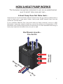
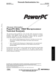
A Heat Pump Does Not Make Heat…
Heat pumps are so extraordinarily efficient because they do not need to produce heat in
order to warm pool or spa water. Rather, heat pumps simply transfer heat from the
outside air into the water.
If one considers Absolute Zero (the point where all heat is absent) occurs at -459º
Fahrenheit, it becomes evident outside air, even at the relative cool temperature of 55º
Fahrenheit, still contains large amounts of heat energy. It is that abundant heat energy a
heat pump captures and places into your pool or spa.
HEAT LADEN
AIR ENTERS
HEAT REMOVED FROM AIR...
COOL AIR OUT
WA
RM
ED
OU WAT
T
ER
CO
OL
IN
WA
TE
R
1
SAFETY INFORMATION
Used and maintained properly, your heat pump will provide year-upon-year of safe and
economical service. However, as with any mechanical or electrical device, to get the
most from your heat pump–while insuring personal safety for you and others–certain
operational and maintenance factors must be observed.
Likewise, excepting a few minor owner-capable maintenance items (explained later in
this manual), repair and service of your heat pump must be performed only by experienced service personnel. Should you, the owner, suspect your heat pump is not performing properly, by referring to the section in this manual entitled: "Troubleshooting,"
you will be able to determine if a call for service is required. Your installer can be one
source of service, or AquaPro Customer Support personnel stand ready to assist you
at: (877) 278-2797. For questions concerning installation, modifications, operation,
service and upkeep, please contact your installer or AquaPro Customer Support. Warranties may be voided if the heater has been used, maintained, or repaired improperly.
In addition to voiding the manufacturer’s warranty... unapproved installation methods,
nonstandard modifications, poor or incorrect maintenance, service by unqualified personnel, or improper use of the heater may result in personal injury and/or property
damage. For personal safety, and to avoid damage to equipment, follow all safety
instructions displayed on the heat pump and within this manual.
Safety Signals
Throughout this manual the following two safety signals are placed where particular care
is required. Please note "WARNING" relates to personal safety, while "CAUTION" signals
promote avoiding damage to equipment.
WARNING !
Failure to heed the following may result in permanent injury or death.
“Warning” signal appears in this manual where special attention is required for personal
safety. (Specific instructions will appear in this box.)
CAUTION !
Failure to heed the following may result in equipment
damage.
“Caution” signal appears in this manual where special care is required to avoid
equipment damage. (Specific instructions will appear in this box.)
2
Notice: Heater NOT Repairable by Owner
WARNING !
Failure to heed the following may result in permanent
injury or death.
Heat pumps contain no owner-repairable components. Repairs must not be attempted
by untrained and/or unqualified individuals. If service is deemed necessary, contact
installing dealer or AquaPro Customer Support at (877) 278-2797.
Refrigerant Circuit Service Only by
Qualified, EPA Certified Technician
WARNING !
Failure to heed the following may result in permanent
injury or death.
Heater contains refrigerant under pressure. Repairs to the refrigerant circuit must not be
attempted by untrained and/or unqualified individuals. Service must be performed only by
qualified HVAC technicians. Recover refrigerant before opening system.
Water Temperature Safety
WARNING !
Failure to heed the following may result in permanent
injury or death.
Prolonged immersion in water warmer than normal body temperature may cause a condition known as HYPERTHERMIA. The symptoms of hyperthermia include: unawareness of
impending hazard, failure to perceive heat, failure to recognize the need to exit the spa,
and unconsciousness. The use of alcohol, drugs, or medication can greatly increase the
risk of fatal hyperthermia. In addition, persons having an adverse medical history, or pregnant women, should consult a physician before using a hot tub or spa. Children and the
extreme elderly should be supervised by a responsible adult.
Water Chemistry Safety
WARNING !
Failure to heed the following may result in permanent
injury or death.
Improper water chemistry can present a serious health hazard. To avoid possible hazards,
maintain Pool/Spa water per standards detailed later in this manual.
CAUTION !
Failure to heed the following can result in damage to
equipment.
While your heat
titanium-based heat exchanger provides nearly impervious
protection against poor water chemistry, improper water chemistry may cause expensive
damage to pump, filter, pool shell, etc. To avoid equipment damage, maintain Pool/Spa
water per standards detailed later in this manual.
3
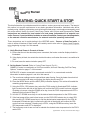
Getting Started
HEATING- QUICK START & STOP
This brief information is provided as an aide to installers, service personnel, and owners. The intent of
this section is to provide rapid access to very basic operational information. Individuals who will be
routinely using, installing, maintaining, and servicing this heat pump, are strongly encouraged to read
this entire manual. Herein, the terms: Heat Pump, Heater, and Unit are used synonymously. These
instructions are intended for local control of a heat pump, independent of an external controller. Owners: if your installation includes an external controller, contact your installing dealer,
or the external controller manufacturer, for external controller operating instructions.
These instructions are for quick-starting in the HEATING mode... Owners of Heat-Cool units, in
order to utilize all features of their heater, will certainly want to also refer to: Owner Level Programming, beginning on page-14 of this manual.
1. Verify Electrical Power is Present at Heater:
A. Ensure that the unit has electrical power connected; the heater controller display should be
illuminated.
B. If the display is blank, be certain the electrical breaker, and heater disconnect, are switched to
“ON.”
C. For now, leave the water circulation pump OFF.
2. Set the Heater Controls (Refer to Control Panel Layout, Pg-12):
OWNER- If heater is connected to a Call-Flex controller, also see “Selecting Call-Flex Pump
Options,” located on page-17 of this manual.
INSTALLER- Is heater connected to an external controller? If so, see external controller
information located on pages 41 and 44 of this manual.
A. The user/owner settings can be made without water flowing. Once the heater has electrical
power connected, with water not flowing, the display should read FLO.
B. Press the MODE button until the HEAT (HEA) indication displays. This action will enable the
remaining programming keys.
C. Using the POOL / SPA selector key, select the POOL mode. An illuminated POOL indicator
light, located on the left side of the display, will confirm the POOL control has been selected.
If heating only a spa, using the DOWN arrow key, lower the POOL temperature until OFF is
displayed; then proceed to Step-“E.”
D. Use the UP / DOWN arrow keys to set the desired water temperature for the POOL water.
E. If the heat pump will be used to heat a spa, use the POOL/SPA selector key to select SPA,
then use the UP / DOWN arrow keys to set the desired water temperature for the SPA. An
illuminated SPA indicator light, located on the left side of the display, will confirm the SPA
control has been selected. If heating only a POOL, using the DOWN arrow key, lower the
SPA temperature until OFF is displayed.
F. The heat pump controls are now set to maintain the desired water temperature for the POOL
and/or SPA.
(Quick-Start & Stop Continued Next Page)
4
HEATING-QUICK START & STOP (continued):
3. To Begin Heating:
A. Verify MODE is set to: HEAT (HEA); then, depending on which body of water is to be heated,
use the POOL / SPA selector key to select POOL or SPA.
B. Position water valves to flow water from the pool or spa, through the heater, and back to the
pool or spa.
C. Start the water pump; the fan will start, and after 4-minute time delay the unit will begin
heating. The selected body of water will be brought to temperature and maintained per the
setting determined previously in: “Set the Heater Controls.”
D. In operation, whenever the actual (displayed) water temperature falls below the desired set
point, after an initial time delay of 4-minutes, the unit will begin heating.
NOTE: THE HEATER CONTROLLER INCORPORATES AN ANTI-SHORT CYCLE TIME DELAY. SHOULD OPERATION BE
INTERRUPTED, COMPRESSOR RESTART WILL BE DELAYED BY APPROXIMATELY 4-MINUTES.
4. Program Filter Pump Run Time:
Most pool/spa systems utilize a timer or multifunction controller to manage filter pump run times.
If your system incorporates such a device, follow the instructions below:
A. It will be necessary to allow the filter pump to run continuously until the water has reached the
desired temperature. If a timer controls the pool filter pump, it will be necessary to override
the timer to allow 24-hr. operation.
B. Once the desired temperature has been obtained (1-4 days), reset the pump control device.
Colder months require longer running times–generally eight to twelve hours/day.
C. A heat pump can only operate when the filter pump is running. Therefore, it may be
necessary–during cooler weather–to extend the water
s hours of daily operation.
The increased run time is necessary in order to keep up with increased, weather-related
heat losses.
5. Continuous Usage and Water Around Heater:
Condensation... After the heat pump has been operating for some time, water may be observed
surrounding the heater. The moisture seen is condensation produced as a normal by-product of
transferring heat from the air into the pool or spa water. Quantities of 6-8 gallons of water produced
per hour are common if the air humidity is high. Conversely, a low humidity condition may result in
no condensation being produced. (If water around unit seems excessive, to troubleshoot, see
page-26, “Water Coming from the Heat Pump.”)
6. To Stop the Heat Pump:
A. Select: OFF via the MODE selector. This method of shut down preserves the controller
settings;
B. An interruption of water flow–such as when a pump timer is in control–will also halt heat
pump operation.
(End...Quick-Start & Stop)
5
HEATER CONTROLS
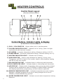
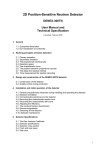
Control Panel Layout
(APPEARANCE VARIES BY MODEL)
Control Buttons, Indicator Lights, & Display
(AS INDICATED BY CIRCLED NUMBERS)
1) POOL / SPA SELECTOR – Selects either pool or spa thermostat.
2) COOLING INDICATOR LIGHT – Indicates unit is cooling. (Note: this light
nonfunctional with heat-only models.)
3) UP ARROW – Increases temperature setting. (Maximum setting is 104 oF)
4) DOWN ARROW – Decreases temperature setting. (Minimum setting is 45 oF)
5) HEATING INDICATOR LIGHT – Indicates unit is heating.
6) MODE SELECTOR – Used to select between the Heating, Cooling, AutoChangeover, and Off for Heat & Cool models. Used to select between Heating
and Off for heat-only models.
7) SPA INDICATOR LIGHT – Indicates heater is referencing spa thermostat.
8) POOL INDICATOR LIGHT – Indicates heater is referencing pool thermostat.
9) LED DISPLAY – Displays water temperature when no keys are being pressed.
Displays desired temperature when UP ARROW or DOWN ARROW is pressed.
Also displays operational, programming, and fault codes as applicable.
10) DESIRED TEMPERATURE LIGHT – Indicates temperature set point is being
displayed. Indicates temperature set point is being changed due to the UP
ARROW or DOWN ARROW being pressed.
11) WATER TEMPERATURE LIGHT – Indicates current water temperature is being
displayed.
6
HEATER CONTROLS...continued
Operational & Programming Codes
THE FOLLOWING CODES WILL BE DISPLAYED AS PART
OF THE NORMAL OPERATION OF THE HEATER:
FLO..... No Water Flow Detected. This code appears whenever the circulating pump is off, or when
the heater is not receiving correct water flow.
OFF..... System is Off. This code appears whenever heater has been turned off via the mode
selector button, or when the temperature set point has been lowered below 45 oF.
CFI...... Celsius/Fahrenheit Selection. This is a programming entry point to select in which format
the water temperature will be displayed.
ULC..... User Lock Code. This is a programming entry point; when activated, steps to the next
menu level: ELC.
ELC..... Enter Lock Code. This a programming entry point; permits end user to select a secret
code, thereby limiting access to the owner settings.
CFO..... Call Flex Options. This is a programming entry point; when used in conjunction with an
AquaCal Call/Flex add on kit, permits the use of CALL or FLEX options.
FS....... Heater in Defrost Mode (Applicable to Heat-Only Units, only). This code appears as a
normal display during periods of lower air temperatures. Sequence follows:
Heat-Only Defrost Sequence: Fan continues to run and compressor is off. Compressor
will restart when air coil temperature rises to approximately 38°F.
LOC..... This is a Service Entry Point (not intended for use by the owner). The[LOC] code permits
service personal to enter a factory code for access to adjustable calibration and sitedependant setup parameters. Service adjustments are available to authorized installation
and service personnel, only.
CAUTION !
Failure to heed the following may result in equipment damage and voiding of manufacturer s warranty.
Heat pumps contain no owner-serviceable components. Owner-initiated adjustments, beyond
the controller “LOC” code, must not be attempted. If adjustments are deemed necessary, the
owner should contact installing dealer or AquaPro Customer Support at (877) 278-2797.
7
HEATER CONTROLS...continued
Start Up & Setting Operating Controls
Owner-Level Programming Instructions (Complete)
Covered within this section are features and settings typically accessed first by the installer, and then
remaining accessible by the end user (the owner). These features reside at the Level-1 access point
within the microprocessor. Note: if preferred, all programming may be performed without water flow,
waiting to start the water pump as the last step in the set up and run process.
1. Applying Power to The Controller:
A. When power is first applied, the controller performs a lamp test and the display will read
[888]. Following [888] the software version will display briefly.
B. The control will then display the actual water temperature, provided the circulating pump is
operating, and adequate water is flowing through the heater.
C. If the pool-circulating pump is off, the control will display: [FLO]. This code message
indicates no (or insufficient) water is being circulated through the heat pump.
2. MODE Controls Explained, and Starting the Heat Pump:
A. Once electrical power is supplied to the heat pump, sufficient water is circulating, and the
heater controller has successfully completed its self-test, the heater is ready to operate.
B. The heat pump is shipped with the controller [MODE] function set to “OFF”. There are two
ways to switch the heat pump OFF: First Method- One of the functions of the [MODE]
button is “OFF”. Second Method- The thermostat set point can be lowered to a position
below the minimum temperature setting (45oF); this action will cause the display to read
“OFF”. To switch the unit ON, first use the mode button to select the HEAT mode—for Heat
Only models—or, if the heat pump is a Heat and Cool model, use the mode button to select
one of the following modes: HEAT, COOL, or ACH (Auto-Changer Over). In the [OFF] mode,
the actual water temperature will be displayed as long as the circulating pump is operational
and correct water flow is present. In the event water is not circulating through the heat pump
(or flow is insufficient), the controller will display the [FLO] (No Water Flow) code message.
C. Using the UP ARROW key, increase the desired temperature until it exceeds the value of the
actual temperature displayed. (Note: See # “8,” later in this section, if “000” is displayed upon
pressing either the up or down arrow keys.) Once the desired temperature has been
entered, the display will read the actual temperature and the heat pump will start to operate.
Both the compressor and the fan must be operating before the “Heating” LED will illuminate.
(Note: When MODE function is OFF, the current water temperature will be displayed; no
functions, values, or programming will be available for adjustment.)
3. Turning The Heat Pump Off:
A. Method 1: using the [MODE] key, press the key until the display reads “OFF” The
heater will shut off and remain off until the [MODE] key is used the select an operational
mode. This is the preferred method for shutting off the heat pump.
B. Method 2: using the DOWN key, press the key until the desired water temperature reaches
45oF (minimum setting); then, press the DOWN key one more time, causing the display to
read “OFF”. This method is typically used in conjunction with 2-wire external controllers;
these controllers are equipped with their own thermostats.
(Continued on Next Page)
8
HEATER CONTROLS...continued
Start Up & Setting Operating Controls
Owner-Level Programming Instructions... continued:
4. Selecting Pool/Spa Thermostat Settings:
A. Press the [POOL/SPA] key to toggle between the pool and the spa temperature set points.
B. The pool/spa LED indicator lights, located to the left of the temperature display, will confirm
the selected set point.
5. Changing The Pool Temperature Set Point:
A. Using the [POOL/SPA] key, select the POOL temperature set point. The pool set point
indicator light will confirm the selection.
B. The pool temperature set point is adjustable from a minimum of 45 oF to a maximum of
104oF. Pressing the [UP ARROW] key will raise the set point 1-degree for every push of the
button. Pressing the [DOWN ARROW] key will lower the set point 1-degree for every push
of the button.
6. Changing The Spa Temperature Set Point:
A. Using the [POOL/SPA] key, select the SPA temperature set point. The spa set point indicator
light will confirm the selection.
B. The spa temperature set point is adjustable from a minimum of 45 oF to a maximum of
104oF. Pressing the [UP ARROW] key will raise the set point 1-degree for every push of the
button. Pressing the [DOWN ARROW] key will lower the set point 1-degree for every push
of the button.
7. Selecting Between oF and oC:
A. Simultaneously press and hold both the [UP ARROW] and [DOWN ARROW] keys until
[CF1] (Celsius / Fahrenheit) code appears.
B. With the [CF1] code displayed, pressing the [UP ARROW] or [DOWN ARROW] keys will
change the selection code to either “0” or “1”. Select “1” for Fahrenheit temperature display,
or “0” for Celsius temperature display. Once the desired temperature display mode has
been selected, not pressing any buttons for 15-seconds will allow the controller to save the
selection and return to the normal operating mode. Pressing the {POOL/SPA] key will also
save the selection and step to the next menu parameter: [ULC] (User Lock Code).
8. User Lock Code Option [ULC]:
This Option Explained:
Heat pumps are shipped from the factory with the [ULC] option disabled. Enabling the [ULC]
function permits the heat pump owner to restrict access to the
controls. With the [ULC]
function enabled, unless the correct ULC code number is entered, changes to Level-1
programming are not possible. (I.e.: Altering temperature set points, Pool/Spa selection, C/F
display changes, etc., will not be possible). The [ULC] option can be thought of as an electronic
lockable cover for the controls.
(Continued on Next Page)
9
HEATER CONTROLS...continued
Start Up & Setting Operating Controls
Owner-Level Programming Instructions... continued:
8. User Lock Code Option [ULC]...continued:
A. Selecting ULC Option:
1) Press either the UP or DOWN ARROW keys; if “LOC” is momentarily displayed followed
by “0”, the ULC feature is enabled. If “0” displays proceed to “6)” of this section;
otherwise, see number “2,” below.
2) Simultaneously press and hold both the [UP ARROW] and [DOWN ARROW] keys until
[CF1] (Celsius / Fahrenheit) code appears.
3) Press the [POOL/SPA] key once to display [ULC].
4) With [ULC] displayed, pressing either the Up or Down Arrow key will display either “1” or
“0”. Selecting “0” will allow the keypad to remain unlocked. Selecting “1” will enable the
User Lock Code option. Then, to enter a lock code number, press the [POOL/SPA] key
once to display [ELC] (Enter Lock Code).
5) With [ELC] displayed, use the Up or Down arrow keys to select a lock code. The code
can be any number from “00” to “99”. The factory set lock code is “0”. Not pressing any
buttons for 15-seconds will allow the controller to save the selection and return to the
normal operating mode. Pressing the {POOL/SPA] key will also save the selection, and
will step the controller to the next menu parameter: [CFO] (Call Flex Options).
6) Once the ULC option has been enabled, pressing any key will momentarily display
“LOC” followed by “0” (prompting the entry of the correct lock code number). To gain
access to the controller:
a. Using the [UP ARROW] key, scroll to the correct lock code number, then;
b. Press the [POOL/SPA] key… Current water temperature will be displayed… Control
setting can now be viewed or changed as desired.
c. After a period of approximately four (4) minutes, during which time no buttons have
been pressed, the controller will automatically return to the locked mode. Provided
ULC selection is set to “1,” the controller will always fail-safe in the locked mode.
d. Without knowledge of the correct lock code, and with the ULC enabled, control
adjustments will not be possible. Be certain to record your lock code in a safe
place. The lock code may be changed any number of times by following the
instructions detailed in this section.
B. De-Activating the User Lock Code [ULC] function:
1) Following the instructions detailed previously at: “8, 6)”, press any key and enter the
user lock code number; then press the [POOL/SPA] key.
2) Immediately following the entry of the user lock code, simultaneously press and hold the
[UP ARROW] and [DOWN ARROW] keys until the code [CF1] appears on the display.
3) Then, use the [POOL/SPA] key to scroll to the [ULC] message; press the [DOWN
ARROW] key to change the display to “0”. This will disable the User lock function.
(ULC Continued on Next Page)
10
HEATER CONTROLS...continued
Start Up & Setting Operating Controls
Owner-Level Programming Instructions... continued:
C. User Lock Code is Activated, but Pass Number is Not Known (“Back Door Entry”):
Note: Should the ULC option be enabled, and a lock code number other than the factory
default (0) be installed but is unknown, the following procedure may be followed to regain
controller programming access:
1) Simultaneously press and hold the [POOL/SPA] and [UP ARROW] keys until the display
shows “888”. This operation will reset the controller to the factory default settings.
2) When reset to the factory default settings the user lock code [ULC] is deactivated and
the user lock code number [ELC] is reset to “0.”
3) In addition, all other settings are returned to the factory defaults. If an external
controller is in use, contact AquaPro Technical Support Group (877-278-2797); ask for
assistance with re-configuring the controller for use with an external controller.
9. Selecting Call-Flex Pump Options [CFO]:
General Information:
The Call-Flex option automatically adjusts the run time of the water circulator pump, and heater,
based upon changing weather conditions. Without Call-Flex, as weather conditions grow
progressively cooler during winter months, or when unusually cold weather occurs, the run
duration of the circulator pump may require manual adjustments to permit the heater to maintain
or reattain desired water temperature (the water pump must be running in order for the heater to
operate). Likewise, without Call-Flex, one must remember to reset the pump run controls
following the cold weather event. The Call-Flex option greatly reduces the need for seasonal,
manually-made, pump run time adjustments. Call-Flex is a dealer-installed option that does
not come with every heater; if unsure, check with the installing dealer to determine if a call-flex
kit was part of the original installation. If Call-Flex was not part of the installation, and you would like
to have Call-Flex added, your dealer can do so...contact the installing dealer.
If the installation is equipped with the Call-Flex option, the following steps are used to control the
Call-Flex features:
A. Simultaneously press and hold the [UP ARROW] and [DOWN ARROW] keys until the
display shows “CF1”. Press the [POOL/SPA] key three times to scroll the display to [CFO].
B. With the [CFO] (Call-Flex Options) code displayed, use the Up or Down keys to select “0” to
disable the Call Flex Options, “1” to enable the Call Option, or “2” to enable the Flex Option.
Not pressing any buttons for 15-seconds will allow the controller to save the selection and
return to the normal operating mode. Pressing the {POOL/SPA] key will also save the
selection, and will step the controller to the next menu parameter: [LOC] (Service Lock
Code).
C. For further information, please refer to Call-Flex installation instructions, shipped with the
Call-Flex kit. For additional copies of these instructions, contact the AquaPro Customer
Support (877-278-2797).
(End... Owner-Level Programming Instructions)
11
MAINTENANCE
&
OPERATIONAL RECOMMENDATIONS
The information in this section is written primarily for the Home Owner, but may also apply to servicing
dealers or HVAC service centers. This section contains information concerning planned maintenance,
proper water flow, maintaining proper clearances, as well as other vital information. Please read this
section now, and before calling AquaPro Customer Support (877-278-2797).
General Maintenance
Heat pumps should be inspected and maintained on an annual basis by a qualified swimming pool
heat pump specialist. Additionally, if the heat pump is located near the beach or coastal area, where
salt spray and sand can become detrimental factors, more frequent service may be necessary. For
service plan information, please see: Planned Maintenance Program, later in this section, and then
contact AquaPro Customer Support at: 877-278-2797.
While annual maintenance is recommended to maintain your warranty, if you choose not to participate
in the Planned Maintenance Program, rinsing the air coil regularly, and keeping the base of the unit
clear of leaves and debris is a necessity.
Should you as the owner desire to perform the coil rinsing and other cosmetic care of the heat pump,
please contact AquaPro Customer Support: 1-877-278-2797; request the document titled: “Appearance
Care for Air-Source Heat Pumps: Approved Method for Home Owners.”
Safety During Cleaning Operations
WARNING !
Failure to heed the following may result in permanent
injury or death.
POSSIBLE ELECTRIC SHOCK HAZARD . . . Should you decide to wash the heat pump
via water hose, disconnect all power to the pool equipment pad- including, but not limited
to: The heat pump, water pump, and any and all other electrical equipment. Do NOT spray
water directly into electrical components. Do NOT restore electrical power until such time
as all water has dried completely.
CAUTION !
Failure to heed the following may result in damage to
equipment.
Do not use a pressure cleaner to wash heat pump . . . . Damage to evaporator fins, as
well as other components, will result.
12
MAINTENANCE & OPERATION
(continued)
Maintain Proper Water Flow
It is important to operate and maintain the filter according to the manufacturer's specifications.
As a filter gets dirty, the water flow to the heat pump is reduced. The higher the pressure on the
filter gauge, the lower the flow rate.
Similar to a dirty filter, large amounts of debris in the pump and skimmer baskets can reduce
water flow. Keep baskets free of debris.
Check for improper valve settings. A partially closed valve after the filter, or a full-open bypass
around the heater, will cause insufficient water flow through heater.
If the conditions listed above remain unresolved, the water flow through the heater may be
reduced to a point where internal safety devices (i.e.: “HP” or “HP5”) shut the heater off.
Before calling for service, always check the filter, the pump basket, and water valve positions. If
the problem persists, please call AquaPro Customer Support at: (877) 278-2797.
Control Water Chemistry
IMPORTANT! Your heat pump is engineered for exceptional durability and reliability. And, this
heat exchanger—being equipped with titanium tubing—will be nearly impervious to water
chemistry damage. However, other components of the heater, and the remainder of the pool/spa
equipment in general, may be susceptible to damage from prolonged exposure to unbalanced
water chemistry. Likewise, bathers may be exposed to health risks if water chemistry is not
properly maintained.
For the longevity of the entire pool/spa installation, and for the safety of bathers, it is strongly
recommended the water chemistry be checked regularly and maintained within proper norms.
Please see the table, below, for a complete listing of recommended water chemistry levels.
RECOMMENDED WATER CHEMISTRY STANDARDS*
Chlorine . . . . . . . . . . . ........ . . .:
Bromine . . . . . . . . . . . . ........ . .:
pH . . . . . . . . . . . . . . . . . . ..........:
Total Alkalinity . . . . . . . . . ........:
Calcium Hardness . . . . . . . .....:
Total Dissolved Solids . . . . .....:
1.0 – 3.0 ppm in pools, 1.5 – 3.0 ppm in spas
2.0 – 4.0 ppm in pools, 3.0 – 5.0 ppm in spas
7.4 – 7.6 ppm in pools, 7.2 – 7.8 ppm in spas
80 – 140 ppm in pools, 80 – 120 ppm in spas
200 – 400 ppm in pools and spas
1,000 – 2,000 ppm in pools,
1,500 ppm above start-up TDS in spas
* STANDARDS FOR COMMERCIAL APPLICATIONS MAY VARY LOCAL-TO-LOCAL...
ALWAYS MAINTAIN WITHIN LIMITS ESTABLISHED BY AUTHORITY HAVING JURISDICTION.
CAUTION- Pool/Spa Refinishing Operations
During pool refinishing or acid cleaning, the water flow through the heater must be shut off. Water flow
to the heater must remain off until water chemistry is once again in balance and the water is clear in
appearance. Failure to follow these instructions may void heater warranty.
13
MAINTENANCE & OPERATION
(continued)
Control Irrigation and Storm Run Off
Control Irrigation: In regions were wells are used for irrigation, water quality is sometimes poor,
and water spray can damage heater components. Regardless of water quality, it is important
that irrigation be directed away from the heat pump.
Prevent rain water runoff from pouring directly into the heater. The heater is designed to
withstand normal rainfall, but solid streams of water from roof drip-lines may eventually damage
heat pump components.
If the heat pump resides beneath a roof edge, to promote heat pump longevity, a rain leader
(gutter), or rain shield, will be necessary.
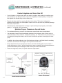
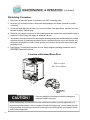
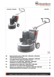
Maintain Proper Clearances Around Heater
For maximum efficiency, proper air flow clearances around heater must be maintained.
It is important to keep the area immediately adjacent to the heat pump clear of items such as
shrubs and bushes, lawn furniture, chemicals containers, etc. These items can prevent air from
circulating fully through the heater, and will result in inefficient operation or damage to the heat
pump.
In addition, do not place objects on top of the heat pump; doing so will block the air from exiting
the heater, and will result in damage to the compressor and fan motor.
Proper clearances are also necessary in order to access the working parts of your heater. A
heater that is easy to "get to," will be a heater that is easy to maintain; service and maintenance
personnel will thank you for keeping the area around your heater unobstructed.
Please see diagrams, below, for specific clearance requirements.
SQ MODELS, 12-INCHES
; ALL OTHER, 6-INCHES
6-INCHES
(REAR)
(REAR)
OVERHANG WITH
GUTTER
RAIN RUN-OFF
MUST BE DIRECTED
AWAY FROM
HEATER.
5 FT. MINIMUM CLEARANCE,
OVERHEAD
30” MINIMUM
CLEARANCE, FRONT
12INCHES
(SIDE)
12INCHES
(SIDE)
SQ MODELS, 12-INCHES
ALL OTHER , 6-INCHES
6” MINIMUM CLEARANCE,
(REAR)
30-INCHES
(FRONT)
14
SIDE VIEW (NO SCALE)
TOP VIEW (NO SCALE)
FRONT-REAR-OVERHEAD
FRONT-SIDES-REAR
MAINTENANCE & OPERATION
(continued)
Heating Tips
Heating in Cooler Weather...
Late night and early morning, generally being the coolest times of the day, are least efficient for heating. For most efficient heating operation, heat pumps should be timed to operate during the warmest,
daylight portions of the day. Conversely, if cooling a pool, it is best to run the equipment at night. Please
set water pump and heat pump controls accordingly.
Pool/Spa Blankets...
A “solar” blanket will significantly reduce your heating bills. Check with the installing dealer to see if
your heat pump was sized to be used in conjunction with a blanket. Blanketed pools will typically lose
only 3 - 4° of heat per night versus 8 - 10° overnight with an un-blanketed pool. Reductions of 40-60%
on heating bills can be achieved by using blankets. (Idea...Contact AquaPro Customer Support
(877-278-2797) to learn about Liquid Blanket innovations.)
WARNING !
Failure to heed the following may result in permanent
injury or death.
Improperly used, Pool-Spa blankets can become a drowning risk to people and pets.
Blankets are not safety covers. They are not designed to support the weight of a person
or pet. Never enter a pool until the blanket is completely removed (under no circumstances
should anyone swim under the blanket). Follow all safety recommendations of the blanket
manufacturer.
Pool and Spa Combination Heating...
Everything stated for heating a pool applies for heating a spa—only the volume of water being heated
is different. Your heat pump comes equipped with two thermostats. One thermostat is for the pool and
the other is for the spa. Simply position the pool and spa isolation valves as directed by your installer;
select the appropriate thermostat (pool or spa), whichever you are heating, and with electrical power
and water flow supplied to the heater, the water will be maintained at set point.
Your system can be automated with the addition of an optional External Flow Switch Kit (P.N. 0040S).
Using this option will save you from having to change the thermostat selector switch each time you
change from pool-to-spa and back again. Or, add a Universal Heater Controller (P.N. 0097TS) and
gain not only automatic thermostat switching, but also automated spa/pool water valve operation. For
details, contact the installer, the distributing dealer, or AquaPro Customer Support (877-278-2797).
Spa Heating & Spa Setback Option...
Air blowing into your spa, while it is being brought to temperature, will very often neutralize or partially
counteract the heat being put into the spa by the heater; this added heat loss equates to increased
time to bring your spa to desired temperature. When heating a spa, be sure to turn off the air blower.
Air induced through the spa jets should also be eliminated, during warm-up, whenever possible.
If your heater is being used to only heat a spa, the POOL thermostat can be used as a setback control:
simply set the pool control at a point 10-15º F below desired spa heat temperature and select the pool
thermostat. This method allows the spa–when not in use–to be held at a heated temperature, but
somewhat lower than normal spa-use temperature. One would want to blanket the spa if using this
setback method. Using spa setback will result in reduced warm up periods over full, cold starts.
15
MAINTENANCE & OPERATION
(continued)
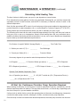
Calculating Initial Heating Time
The time it takes to initially warm your pool or spa depends on several factors.
First, determine how many gallons of water are to be heated. Knowing this, you can then compute the
equivalent pounds of water involved, and the BTU's necessary to heat the volume of water to the
desired temperature.
Next, find the approximate BTU output of your heat pump at the current ambient air temperature; see
product literature at: www.ecoaquapro.com, or contact AquaPro Customer Support (877-278-2797).
Finally, decide upon the temperature at which you plan to maintain your pool or spa.
The following work sheet can be used to calculate approximately how long it will take your heater to
bring your pool or spa up to temperature. Keep in mind heating times will vary somewhat due to
weather conditions during the period that the heater is in use; use of a pool blanket can dramatically
improve heat up and heat maintenance performance.
Pool Volume (Length X Width X Average Depth) = _________ Pool Cubic Feet
X Gallons per cubic ft.(7.5) =
X Pounds per Gallon (8.3) =
_________
Pool Gallonage
_________ Pounds of Water
How many degrees do you want to raise the temperature of the pool?
# of Degrees _________ X Pounds of Water (per above) = __________ BTU s Required
BT s Required (per above) ________
÷
BTU Output of Heater = ______ Hrs. of Operation
Optional Cold Weather Adjustment Factor:
Hrs. of Operation (per above) ______ X 1.25 (60º F outside air (O.A.) Temperature Factor) =
______Hrs. of Operation at 60º F O.A.
At Start Up: Continuous Circulator Pump Operation Required
When starting a heat pump for the first time, it must be permitted to operate, continuously, until the
desired water temperature is attained. This may take several hours, to several days, depending upon
the size of the pool or spa and weather conditions.
If a time clock or similar device controls the operating times of the water circulating pump, temporarily
override the water pump controller, allowing for 24-hour, continuous water pump operation.
Once the body of water has reached the desired temperature, the water pump controller can be reset.
16
MAINTENANCE & OPERATION
(continued)
Seasonal Use & Shut Down
During the Swim Season:
During the swim season, even if the pool or spa is not in use, allow water to flow through the
heater. Doing so eliminates the need to reposition valves when you do wish to heat the pool or
spa.
During periods when heating or cooling is not desired, leave heater controls in the OFF position.
Important !!!
Information Critical to the
Survival of Your Heater
Follows...
Freeze Protection & Extended Shut Down:
In areas where freezing conditions are a rare occurrence, allow the filtration
system to run continuously throughout the freeze period. Typically, during light
freeze conditions, circulating (moving) water will not freeze.
In areas where freezing conditions are prevalent and sustained, the heat pump MUST be winterized; please refer to winterizing instructions, below, and on the following pages.
Winterizing for Hard Freeze Conditions:
CAUTION !
Failure to heed the following can result in damage to
equipment and/or property.
Failure to properly winterize heat pump may result in serious equipment damage. Freeze
damage is not covered under the heat pump warranty.
CAUTION !
Failure to heed the following can result in damage to
equipment and/or property.
While the plumbing connections are in the winterized condition (not fully tightened), it is
imperative pool/spa water not be circulated through the heat pump. Loss of water through
loose plumbing connections may result in damage to circulating pump, pool/spa structure,
and/or other equipment.
(Winterizing continued on page following)
17
MAINTENANCE & OPERATION
(continued)
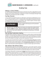
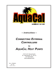
Winterizing Procedure:
1. Disconnect all electrical power to the heater; turn OFF circulating pump.
2. At the two (2) connection unions, disconnect the plumbing to the heater (removal is counterclockwise).
3. Locate the hand drain plug at lower, front corner of heater. See figure below. (position may vary
between models). Remove plug.
4. Permit all of the water to drain out of the condenser and then replace the plug; thread the plug in
clockwise until just snug, then apply an additional 1/8 turn.
5. To prevent insects and vermin from entering the plumbing during the winterized period, partially
reconnect the two (2) plumbing connection unions: couple each union one or two threads; this
will permit condensation to drain, but will prevent most insects and animals from entering the
plumbing circuit.
6. Next Season: To ready the heat pump for use, simply retighten plumbing connection unions.
Hand-tight is generally sufficient.
LOCATION OF EXTERNAL DRAIN PLUG
-EXACT LOCATION
WILL VARY BY MODEL-
CAUTION !
Failure to heed the following can result in damage to
equipment and/or property.
While the plumbing connections are in the winterized condition (not fully tightened), it is
imperative pool/spa water not be circulated through the heat pump. Loss of water through
loose plumbing connections may result in damage to circulating pump, pool-spa structure,
and/or other equipment.
18
MAINTENANCE & OPERATION
(continued)
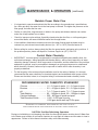
Planned Maintenance Program
Just as you would have yearly service performed on your air-conditioning system, regular inspection
and maintenance of your AquaPro heat pump will insure highest operating efficiencies. A regularly
maintained heater will protect your investment, and will potentially extend the useful life of your heat
pump far beyond the warranty period. Our expertly trained factory service technicians offer comprehensive maintenance procedures designed to insure your heat pump–over the coming years–will continue to operate efficiently and reliably.*
The 20-Point Planned Maintenance Service Includes the Following:
>
Check Water Flow
>
Clean Evaporator Coil
>
Check Relay Contacts
>
Check Capacitor Values
>
Check Refrigerant Levels
>
Clean Heat Pump Cabinet
>
Check Fan Blade Clearances
>
Check Flow/Pressure Switch
>
Check Electrical Connections
>
Check Proper Voltage To Unit
>
Oil Fan Motor (As Applicable)
>
Check Fan Motor Amperage Draw
>
Check Pool & Spa Water Chemistry
>
Check and Clean Condensate Drains
>
Check Compressor Amperage Draw
>
Check Water Pump Amperage Draw
>
Acid Wash Source Coil (As Applicable)
>
Check Air Temperature Change Through Evaporator
>
Check Operating Controls and Temperature Sensors
>
Check Water Temperature Change Through Condenser
We recommend Preventive Maintenance be performed starting one (1) year after the installation of the
heater.
* FACTORY PM SERVICE NOT AVAILABLE IN ALL REGIONS; PLEASE CONTACT AQUAPro CUSTOMER SUPPORT FOR ADDITIONAL
INFORMATION (877) 278-2797.
19
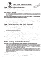
TROUBLESHOOTING
Heat Pump Fails to Operate...
Is the display illuminated?
..
51.
e
pag es”
e
e
d
o s or Co
s
l
A
r
“Er
If not, ensure the main breaker (located at the power supply panel) and the disconnect switch
(located near the heat pump) are both turned ON.
Is the code “FLO” displayed?
If so, check to be sure that the circulating pump is operating and the filter is clean. There may also
be a valve positioned incorrectly allowing water to bypass the heat pump. Be sure water is flowing
through the heater.
Is the Pool or Spa thermostat selected for the correct body of water to be heated, and
have you tried selecting a higher temperature setting?
If not, the actual water temperature may be above that of the selected thermostat. Raise the
desired water temperature above the actual water temperature; the fan should start, and after
approximately four (4) minutes, the “Heating” light should illuminate. If the heat pump still fails to
start, and the unit is not in defrost (heat-only unit defrost display code is: “FS”), contact AquaPro
Customer Support: 877-278-2797.
Heat Pump Running... but is it Heating?
Is the air blowing out of the top of the unit noticeably cooler than the surrounding air?
(With heating indicator light illuminated, a 9°F to 12°F difference is typical.) If not, contact AquaPro for service at: 877-278-2797. But first, be sure all air coil surfaces are free from obstructions–
low roof overhangs, landscaping, walls, fences, etc., can restrict air flow. The heat pump needs
good airflow to operate at peak efficiency.
How many hours/day does the circulating pump operate?
Cooler weather conditions, or heating to a higher than normal temperature, may necessitate
running the heat pump for a longer period of time. Was the heater sized considering the use
of a pool blanket (check with installing dealer)? A blanket can be useful in permitting shorter
run times, in turn leading to substantial energy cost savings.
What is the outside air temperature?
The heat pump may be in the defrost mode if air temperatures are below 50°F. With Heat-Only
models, if the heater is in defrost, the code: ”FS” will be displayed. If air temperatures are not cold,
but the heater remains in defrost, contact AquaPro Customer Support at: 877-278-2797.
Water Coming from the Heat Pump...
Is it a leak or just condensation from normal operation? Here's how to find out.
Test the water draining out the heater base for the presence of the sanitizer being used in the pool
or spa. Using a water test kit, or a test strip, check a sample of the water for chlorine or bromine.
If the sample tests positive for sanitizer, call AquaPro for service at: 877-278-2797. If the test is
negative, the water is probably harmless condensate.
Or, as an alternate method, shut the heat pump off, leaving the circulation pump running. Within a
few hours, there should be a marked reduction in the amount of water seen around the bottom of
the heat pump. If the water appears to be drying up, the water is probably harmless condensate,
indicative of normal operation.
20
NOTE: The water test method will not be effective if an ionizer or ozone generator is being used to
produce the sanitizing agent.
CAUTION! If after testing, a water leak is suspected, immediately shut OFF the water pump and
contact AquaPro Customer Support: 877-278-2797.
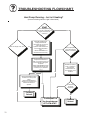
TROUBLESHOOTING FLOWCHART
Heat Pump Fails to Operate
START
START
Y es
No
Is the Display Illuminated?
IstheDisplay Illuminated?,
Display is illuminated. If
Display
is illuminated.
"FLO"
is display
ed, If
"FLO"
is display
ed,
check
to be
sure the
check to be
sure
circulating
pump
is the
circulating
pump
is
operating
and the
f ilter
andmay
the f ilter
isoperating
clean. There
is clean.
also
be a vThere
alv e may
also incorrectly
be a v alv e .
positioned
positioned
incorrectly
.
Be
certain water
is
Be certain
water
f lowing
through
the is
f lowing
through the
heater.
heater.
If not, ensure the main
If not,(located
ensure the
main
breaker
at the
breaker
(located
at the
power
supply
panel)
power
supply panel)
and
the disconnect
and (located
the disconnect
switch
near
switch
(located
the
heat pump)
arenear
the heat
pump)
both
turned
ON. are
both turned ON.
Y es
Is the heater
Is the
heater ?
operating
correctly
operating correctly ?
No
Is the Pool or Spa
Is the selected
Pool or Spa
thermostat
f or
thermostat
selected
the
correct body
of f or
the to
correct
body of
water
be heated,
water
toybe
and
hav e
ou heated,
tried
and havaehigher
y ou tried
selecting
selectingsetting?
a higher
temperature
temperaturesetting?
Y es
Is the heater
Is the
heater ?
operating
correctly
operating correctly ?
No
The heater is equipped
The heater
is equipped
with
a f iv e minute
with
a f iv at
e minute
delay
. Wait
least
f iv e
minutes
to at
allow
delay
. Wait
least
the
to reset.
f ivtimer
e minutes
to allow
the timer to reset.
Problem
Problem
Solved.
Solved.
(Verif
y water
(Verif y water
temperature
temperature
settings
are as
settings
desired.)are as
desired.)
Y es
Is the unit operating
Is correctly
the unit operating
?
correctly ?
No
Contact
Contact
AquaPro
AquaCal
for Assistance at
for
Assistance at
877-278-2797
800-786-7751
21
TROUBLESHOOTING FLOWCHART
Heat Pump Running... but is it Heating?
(Assumes Heating Indicator Light is Illuminated)
START
START
Is the air being
discharged
thetop
airof
being
out ofIsthe
the discharged
heater 9-12
out
of the cooler
top of the
degrees
thanheater
the 9-12
degrees
cooler
outside
air? than the
outside air?
No
Does the display read : "FS" ?
Does the display read : "FS" ?
Yes
Yes
HEATONLY MODELS: "FS"
HEAT
ONLY
MODELS:
display
ed indicates
air "FS"
displaymay
ed indicates
airto
temperature
be too low
support the
heater's
temperature
may
be too low to
operation.
Heater
will
remain in
support
the
heater's
operation.
will remain in
def
rost untilHeater
air temperature
def rost until
air temperature
rises.
rises.
HEAT-COOLMODELS:"FS"
indicates
heater isMODELS:"FS"
def rosting.
HEAT-COOL
indicates heater is def rosting.
Is the pool pump timer
the
poolextended
pump timer
setIsto
allow
operation
theextended
heater?
set to of
allow
operation of the heater?
HEAT ONLY MODELS: Has the air
HEAT
ONLY remained
MODELS:abov
Has ethe air
temperature
remained
38ºFtemperature
f or sev eral hours
andabov
"FS"e
has
been
throughout
38ºF
f ordisplay
sev eraledhours
and "FS"
thedisplay
period?
has been
ed throughout
period?Has "FS"
HEAT-COOLthe
MODELS:
HEAT-COOL
MODELS:
"FS"
remained
display
ed longerHas
than
remained(Ifdisplay
ed longer
5-minutes
y es, shut
heaterthan
5-minutesof(Iff .)?
y es, shut heater
of f .)?
Extend the pool pump's
hours
of the
operation
to
Extend
pool pump's
accommodate
hours
of operation to
accommodate
additional
heater run
additional
run
time
required heater
in cooler
time
required in cooler
conditions.
conditions.
Yes
No
HEATONLY MODELS: Ambient
conditions
too MODELS:
cold to operate
HEATONLY
Ambient
conditions
too cold to operate
heater.
HEAT-COOLheater.
MODELS: "FS"
HEAT-COOL
MODELS:
"FS"
display
ed f or 5-minutes
or less
indicates
def rostor less
display
ed normal
f or 5-minutes
operation.
indicates
normal def rost
operation.
No
Yes
No
Is the heater
Is the
heater
perf
orming
perf orming
adequately
?
adequately ?
No
Problem
Problem
Solved.
Solved.
Yes
Call AquaPro
Call AquaCal
for Assistance:
for Assistance:
877-278-2797.
800-786-7751.
22
Problem
Problem
Solved.
Solved.
TROUBLESHOOTING FLOWCHART
Water Coming from Heat Pump
START
START
Has the "Heating"
lamp been
illuminated?
Has the
"Heating" lamp been
illuminated?
Y es
When the heater is operating,
thetoheater
is operating,
it isWhen
normal
produce
up to 8
itgallons
is normal
to produce up to 8
of condensation
gallons
condensation
(water)
per of
hour.
If water
(water)seems
per hour.
If water
drainage
excessiv
e,
proceed seems
to TESTING.
drainage
excessiv e,
proceed to TESTING.
Sanitizer Test
Did the test results
Did the
results
indicate
thetest
presence
indicate
the presence
of sanitizer?
of sanitizer?
No
If heater has not run recently ,
If and
heater
hasis
not
run recently ,
water
coming
and
water is
coming
f rom the
heater,
heater
may
f rom
heater may
havthe
e aheater,
water leak.
hav e a water leak.
TESTING:
TESTING:
If using chlorine or bromine
as a pool/spa sanitizer,
use
test chlorine
strip or test
kit to determine
whether
the
If ausing
or bromine
as a pool/spa
sanitizer,
water
is test
f romstrip
the or
pool
orkit
is normal
condensation.
use a
test
to determine
whether the
water is f rom the pool
ORor is normal condensation.
OR
An alternativ e method of determining
a water leak in
Anheater
alternativ
method
of determining
water
leak in
the
is toeturn
the heater
of f f or aaf ew
hours,
leav
the water
running,
water
the eheater
is to pump
turn the
heater and
of f fsee
or aiff ew
hours,
topump
come frunning,
rom the and
heater.
leavcontinues
e the water
see if water
continues to come f rom the heater.
Turn- Of f Test
No
This would
This
indicate
thewould
water
indicateisthe
water
present
f rom
present
normalis f rom
normal
condensation.
condensation.
No
Does water continue
Does
water
to drain
f rom
thecontinue
heater
af ter
heater
tothe
drain
f rom has
the been
heater
aff ter
has been
of
f orthe
sevheater
eral hours?
of f f or sev eral hours?
Problem
Problem
Solved.
Solved.
Y es
Shut off Water Pump
Shut off Water Pump
and Call AquaPro for
and Call AquaCal for
Assistance:
Assistance:
877-278-2797
800-786-7751
Y es
23
CONTACTING THE FACTORY
What We Need to Know When You Call Us
If you should need to call AquaPro for service or parts, please have the following information ready:
Model: ________________________________
Serial Number: __________________________
}
Look for this information on
sticker located at top of front
cover of this manual; otherwise,
see data plate on side of heater.
Installation Date: ________________________
}
Refer to installer s invoice for
this information.
Having the above information ready will speed the service process and allow
us to respond more quickly. A brief but concise description of what the unit is,
or is not doing, will also help us to help you.
Please call toll-free at: (877) 278-2797. We are here to serve you from 8 a.m.
to 5 p.m. EST, Monday through Friday. If calling after hours, our voice mail
system will handle your call. Be sure to leave your name, complete address,
and telephone number.
If you prefer, you may FAX the information to: (888) 610-3839.
(Be certain to provide your full address and a daytime telephone number.)
Thank You !
24
LIMITED WARRANTY
For (7) years for the state of Florida and (2) years for all other US states and Canada, Heating Solutions, LLC will repair or replace, at its option, for the original
owner any parts of its Heat Pumps (“Product”) which are found upon examination to be defective in materials or workmanship. This Limited Warranty covers
labor for a period of two (2) years for Product installed and sold within the state of Florida and Arizona, for (1) year for product sold and installed in all other US
states and Canada.
For five (5) years from the date of purchase, Heating Solutions, LLC will repair or replace, at its option, for the original owner, the compressor (part only), found
upon examination to be defective in materials or workmanship. The manufacturer’s Titanium Heat Exchanger carries a lifetime warranty on the titanium tubing
part only. Therefore, this warranty for the Titanium Heat Exchanger will NOT be void due to unbalanced or improper pool chemistry. This warranty for the
Titanium heat exchanger WILL be void ed if chemicals are added upstream of the heat pump.
Please call 1-877-278-2797 for instructions. Be prepared to provide the model number and serial number when exercising this limited warranty.
Purchaser must pay all transportation charges on products or parts submitted for repair or replacement. If a local warranty center requires a service fee for
inspection of the model, this charge will be the responsibility of the homeowner.
All non-warranty service charges are the responsibility of the original owner. Failure to pay for non-warranty service charges will void this Limited Warranty.
This Limited Warranty does not cover Products that have been damaged as a result of accident, abuse, misuse, neglect, improper installation, improper
maintenance or failure to operate in accordance with written instructions. All maintenance and service must be performed by service agents approved.
Any unauthorized alteration or repairs will void this Limited Warranty.
THERE IS NO OTHER EXPRESS WARRANTY, IMPLIED WARRANTIES, INCLUDING THOSE OF MERCHANTABILITY AND FITNESS
FOR A PARTICULAR PURPOSE, ARE LIMITED TO ONE(1) YEAR FROM THE DATE OF PURCHASE. THIS IS THE EXCLUSIVE REMEDY
AND ANY LIABILITY FOR ANY AND ALL INDIRECT OR CONSEQUENTIAL DAMAGES OR EXPENSES WHATSOEVER IS EXCLUDED.
Some states do not allow limitations on how long an implied warranty lasts, or do not allow the exclusions or limitations of incidental or consequential
damages, so the above limitations might not apply to you. This limited warranty gives you specific legal rights, and you may also have other legal rights
which vary from state to state. In no event, whether as a result of breach of contract warranty, tort (including negligence) or otherwise, shall or its suppliers
be liable for any special, consequential, incidental or penal damages including, but not limited to loss of profit or revenues, loss of use of the products or any
associated equipment, damage to associated equipment, cost of capital, cost of substitute products, facilities, services or replacement power, downtime
costs, or claims of buyer’s customers for such damages.
This Limited Warranty does not include freight charges for equipment or component parts, to and from the factory, services such as maintenance or
inspection, repair or damage due to negligence such as freezing conditions, incorrect installation, nor acts of God. It also does not include refrigerant or other
expendable materials. The liability of shall not exceed the repair or replacement of defective parts under this Limited Warranty. This Limited Warranty also
does not include unnecessary service calls due to erroneous operational reports, external valve positions, or electrical service. If a nonwarranty service call is
made, and the homeowner is unwilling to pay for the service call, this Limited Warranty will be voided. This Limited Warranty is voided if the product is
repaired or altered by any persons or agencies other than those authorized by. This Limited Warranty applied only within the continental USA. For warranty
outside the continental USA, contact.
You M UST retain your purchase receipt along with this form. In the event you need to exercise a warranty claim, you MUST present a copy of the purchase
receipt at the time of service. Please call 1-877-278-2797 for service or return authorization and instructions.
DO NOT MAIL THIS FORM. Use this form only to maintain your records.
MODEL NO.__________________________
SERIAL NO._______________________________
INSTALLATION DATE _______________________
25