1
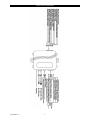
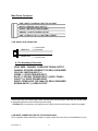
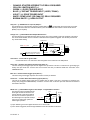
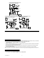
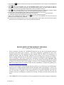
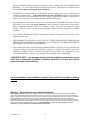
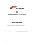
E3
PROFESSIONAL REMOTE ALARM SYSTEM
INSTALLATION MANUAL
This unit is designed for professional installation only and must be installed by an
Encore authorized dealer. Please register this product at
www.encoreautomotivesystems.com.
E3 IN REV. A
1
Precautions: Please read carefully
This Remote Starter with Alarm and Keyless Entry System has been designed to be installed BY PROFESSIONAL
INSTALLERS on fuel-injected vehicles with an automatic transmission ONLY.
Never install this remote starter on a manual transmission vehicle.
This system must be installed and wired through a safety switch so it will not start in any forward or
reverse gear.
Once you install this system, you must verify that the vehicle will not start in any forward or reverse
gear, regardless of the type of vehicle.
Read the operation manual for operating.
Do not install any component near the brake, gas pedal or steering linkage.
Some vehicles have a factory installed transponder immobilizer system that can severely complicate
the installation. There is a possibility that this system cannot be installed on some immobilizer-equipped
vehicles.
Most vehicles have an SRS air bag system. Use extreme care and do not probe any wires of the SRS
system.
Disconnect the car battery before beginning work on the vehicle.
Check behind panels before drilling any holes. Ensure that no wiring harness or other components
are located behind the panels that would otherwise be damaged.
Do not use conventional crimp lock, bullet on any wiring. Poor wiring, i.e. taped joints will possibly
introduce unreliability into the alarm system and may result in false alarms or incorrect operation. We
suggest soldering all connection points.
Install the wiring neatly under carpets or behind trim to prevent possible damage to wires.
FOR AUTHORIZED DEALER TECHNICAL SUPPORT, PLEASE CALL
Toll Free:
(855) GO-ENCORE : 8:00 am TO 5:00 pm
PST.
WARNINGS:
As with any product that performs automatic functions, there are certain safety precautions that you must practice and be aware of.
E3 IN REV. A
2
INSTALLATION DIAGRAM
E3 IN REV. A
3
Main Power Connector
RED / WHITE: PARKING LIGHT RELAY INPUT
WHITE: PARKING LIGHT OUTPUT
BLACK : MAIN SYSTEMS GROUND
BROWN : POSITIVE SIREN OUTPUT
RED : FUSED 12 VOLT (+) BATTERY POWER
3 PIN, DOOR LOCK CONNECTOR
1. Blue Wire
( - ) Unlock Pulse
(+) Lock Pulse
3. Green Wire
( - ) Lock Pulse
( + ) Unlock Pulse
8 - Pin Accessory Connector
-
GRAY WIRE / CHANNEL 3 NEGATIVE TRUNK OUTPUT
ORANGE :STARTER INTERRUPT O/P RELAY REQUIRED
YELLOW / IGNITION INPUT (+)
GREEN / (-) DOOR TRIGGER INPUT
BLUE / (-) INSTANT TRIGGER INPUT ( HOOD, TRUNK)
VIOLET / (+) DOOR TRIGGER INPUT
WHITE / DOME LIGHT (OR CH#4 O/P) RELAY REQUIRED
BROWN/ WHITE / (-) HORN OUTPUT.
WIRING
Keep wiring away from moving engine parts, exhaust pipes and high-tension cable. Be sure to tape wires
that pass through holes on the firewall to prevent fraying.
CAUTION: Do not connect the wire harness to the control module until all wiring to vehicle is complete.
2 PIN WHITE CONNECTOR (THE LED STATUS INDICATOR):
The led indicator status should be mounted in a highly visible area such as top of the dashboard, on top
E3 IN REV. A
4
of the shifter console or on the dashboard face. Leave at least 6mm space behind the mounting location
for LED housing. Once a suitable location is chosen, drill a 6mm hole. Run the LED wires through the
hole then press the 2 pin LED housing into place. Route the LED wires to the control module.
5 PIN WIRE HARNESS:
RED / WHITE WIRE –PARKING LIGHT RELAY INPUT —
The RED/WHITE wire is the input to the flashing parking light relay. The connection of the RED/WHITE
wire will determine the output polarity of the flashing parking light relay.
If the vehicle you are working on has +12volt switched parking lights, you don’t need connect this wire.
This wire is already connected to +12volt.
If the vehicle’s parking lights are ground switched, cut the RED/WHITE wire, connect the RED/WHITE
wire to chassis ground.
WHITE WIRE — PARKING LIGHT RELAY OUTPUT
(+12 V 10A OUTPUT) —
Connect the WHITE wire to the parking light wire coming from the headlight switch. Do not connect the
WHITE wire to the dashboard lighting dimmer switch. (Damage to the dimmer will result). The limitation
of the WHITE wire is 10 AMP max. Do not exceed this limit or damage to the alarm and parking relay
will result.
BLACK WIRE — SYSTEM GROUND –
This is the main ground connection of the alarm module. Make this connection to a solid section of the
vehicle frame. Do not connect this wire to any existing ground wires supplied by the factory wire loom,
make the connection to the vehicle’s frame directly.
BROWN WIRE – (+) SIREN OUTPUT –
This wire is provides power to the supplied siren. Connect the Brown wire to the Red wire of the siren.
Connect the Black wire of the siren to a stable chassis ground.
RED WIRE — SYSTEM POWER (+12V CONSTANT) —
The RED wire supplies power to the system. Connect this wire to a stable constant +12 volt source.
2 PIN BLUE CONNECTOR FOR THE VALET SWITCH:
Select a mounting location for the switch that is easily accessible to the driver of the vehicle. The switch
does not have to be concealed, however, concealing the switch is always recommended, as this
provides an even higher level of security to the vehicle. Mount the valet switch in a hidden but
accessible location. Route the valet switch wires to the control module.
8 - Pin Accessory Connector
-
GRAY WIRE / CHANNEL 3 NEGATIVE TRUNK OUTPUT
E3 IN REV. A
5
-
ORANGE :STARTER INTERRUPT O/P RELAY REQUIRED
YELLOW / IGNITION INPUT (+)
GREEN / (-) DOOR TRIGGER INPUT
BLUE / (-) INSTANT TRIGGER INPUT ( HOOD, TRUNK)
VIOLET / (+) DOOR TRIGGER INPUT
WHITE / DOME LIGHT (OR CH#4 O/P) RELAY REQUIRED
BROWN/ WHITE / (-) HORN OUTPUT.
Gray wire – (-) 200mA Channel 3 (Trunk) Output –
on transmitter for two seconds, the current
This will become a 1 second pulse ground by activate (button 3)
capacity of this wire is 200 mA. This feature allows you to remote control trunk release or other electric device.
(Realay may be required).
Orange wire – (-) 200mA Grounded Output When Armed –
This wire will become grounded when the alarm is armed. The current capacity of this wire is 200mA. This output
can control starter disable, when an intrusion is detected and the system is triggered. The vehicles prevent from
any unauthorized starting.
IN4003 Diode
Purple wire
87
H2/15: Orange wire
from control module
White wire
86
85
87a
30
H1/1 VIOLET wire (Starter output)
form Heavy Gauge wire harness
Red wire to
Ignition Switch
“Off”
Yello wire
“Acc”
Starter
“On”
“Start”
Cut
X
Yellow wire - 12 volt with the ignition ON +
Connect this wire to a 12 Volt source when the ignition of the vehicle is in the ON position.
Green wire – Negative Door Switch Sensing Input (Zone 3) –
This wire is the ground trigger input wire for negative door pin switch. This wire is connection for "grounding" type
factory door pins locate the "common wire" that connects the door pin switches. Make the connection of the
GREEN Wire here.
Blue wire – Ground Instant Trigger Input (Zone 2) –
This wire is the ground trigger input wire for hood and or trunk pin switches.
Violet wire – Positive Door Switch Sensing Input (Zone 3)–
This wire is the positive trigger input wire for positive door pin switch. This wire is connection for "positive" type
factory door pins(typical FORD MOTOR). Locate the "common wire" for all door pins and make the connection of
the VIOLET Wire here.
White wire – (-) 200mA Dome Light Control Output – Programmable channel 4
This wire becomes grounded when the
Fuse
dome light controls circuit active. The
Courtesy
Light
current capacity of this wire is 200mA.
Door
This wire can control the operation of
Switch
87
the interior lights. An optional 10 Amps
White Wire
87a
+12V
86
relay can be used to this system for
85
30
interior lights operation.
a). Upon disarming, the interior lights will remain on for 30 seconds.
b). If the alarm is triggered, the interior light will flash for the same duration as the siren.
E3 IN REV. A
6
Brown / White wire wire – (-) 200mA Programmable Output Horn Output –
This wire is provided to use the existing
vehicle's horn as the alarm system's
optional's warning audible device. It's a
transistorized low current output, and
should only be connected to the low
current ground output from the vehicle's
horn switch. When the system is
triggered, the horn will sound.
FUSE
White/Blue
wire
+ 12 V
87
86
To horn
87a
85
30
+12V Or Ground
Depending On System
Requirements
Factory Security Rearm Signal Output –(See Alarm Feature Programming) –
This output is programmable. If programmed rearm a factory installed security system. This wire will supply a pulse
whenever the remote start times out or is shut dowm using the transmitter and remote door locking.
3 PIN DOOR LOCK CONNECTOR:
(Maximum 500mA Output)
NEGATIVE TRIGGER DOOR LOCK SYSTEM
Blue Wire
Blue Wire Door Unlock
( - ) Unlock Pulse
(+) Lock Pulse
Red(not used)
Green Wire Door Lock
( - ) Lock Pulse
Green Wire ( + ) Unlock Pulse
To Exiting
Door Lock Relay
POSITIVE TRIGGER DOOR LOCK SYSTEM
5-WIRE ALTERNATING DOOR LOCK
+12V
Green Wire
Master Door
Lock Switch
86
87
3 Pin Plug
To Alarm
87a
85
Blue Wire Door lock
Green Wire Door Unlock
X
+ 12V
Splice
To Exiting
Door Lock Relay
Red +12V
86
87
87a
X
30
Cut the Existing
Lock Wire
To Door
Lock
Motor
85
Blue Wire
To Slave Door
Lock switches
VACUUM OPERATED CENTRAL LOCKING
Green Wire
86
87
87a 30
Door Switch
X Cut
85
3 Pin
Plug To
Alarm
+12V
86
87
Compressor
87a 30
85
Blue Wire
E3 IN REV. A
Locking
Master
Switch
Red (not used)
Splice
Cut the Existing
Unlock Wire
30
Locking
Master
Switch
Red (not used)
VACUUM OPERATED DOOR
LOCKING SYSTEM:
TYPICAL OF MERCEDES BENZ
AND AUDI.
Locate the wire under the driver's kick panel.
Use the voltmeter connecting to ground, verify
that you have the correct wire with the doors
unlocked, the voltmeter will receive "12 volts".
Lock the doors and the voltmeter will read
"0 volt". Move the alligator clip to +12V and
the voltmeter will receive "12 volts". Cut this
wire and make connections. Be sure to program
door lock timer to 3.5 seconds.
(See Alarn Feature B – 3 Programming.)
7
2 STEP DOOR UNLOCK WIRE CONNECTION FOR
5 WIRE ALTERNATING DOOR LOCKS
H2/13:
22-Pin
Plug
From
Alarm
+ 12V
OEM Door Master Lock
87
86
Pink Wire
85
87a
30
Green Wire
+12V
Unlock
Lock
Cut the Unlock Wire
x
85
Red +12V
X
87
87a
Cut the Existing
Lock Wire
30
86
H9:
3 Pin
Plug
To
Alarm
85
OEM Slave
Door Lock
Switch
30
87
87a
Unlock
86
Lock
+12V
Blue Wire
OEM Driver’s
Door Lock Motor
X
To All Other
Door Lock
Motors
Cut Existing Unlock
2 STEP DOOR UNLOCK WIRE CONNECTION FOR
2 STEP DOOR UNLOCK WIRE CONNECTION FOR
GROUND SWITCHED DOOR LOCKS
POSITIVE SWITCHED DOOR LOCKS
H2/13:
22-Pin
Plug
From
Alarm
+12V
OEM Door Master Lock Switch
White/Green
Wire
Unlock
Lock
OEM Door Master Lock Switch
87
White/Green
Wire
Unlock
86
87a
Existing Neg.
Lock Wire
Unlock Wire
Lock
85
Existing Pos.
Unlock Wire
30
Existing Neg.
Green Wire
Door Lock
H2/13:
22-Pin
Plug
From
Alarm
+ 12V
Existing Pos.
Lock Wire
Blue Wire Door Lock
+ 12V
H9:
3 Pin
Plug
To
Alarm
Blue Wire
Door Unlock
H9:
3 Pin
Plug
To
Alarm
87
85
86
OEM Door
Lock Relay
87a
Green Wire
Door Unlock
87
87a
85
86
30
OEM Door
Lock Relay
30
+ 12V
OEM
Door Lock
Motor
OEM Driver's
Door Lock
Motor
X
Cut Existing Unlock
X
Cut Existing Unlock
To All Other
Door Lock
Motors
To All Other
Door Lock
Motors
PROGRAMMING
PROGRAMMING TRANSMITTER:
Note: This mode will only retain the last 4 remote transmitters programmed. If the transmitter memory is exceeded,
the security system will start deleting transmitters from memory in chronological order.
1. Turn the Ignition 'switch ‘OFF/ON’ 4 TIMES and stay in ON position.
“Within 15 seconds”.
2. Push the Valet switch 4 times and hold it on the 4th push until a long chirp is heard then release the valet switch.
You are now in the Transmitter programming mode.
3. Press and hold any button of the transmitter until the siren responds with a confirming chirp, indicating the signal
has been stored into memory.
4. If you have additional transmitters (up to 4) that need to be programmed, repeat step 3 for each transmitter.
Exit: Turn Ignition to 'OFF' position, or leave it for 15 seconds. 3 long chirps & 3 parking light flashes will confirm exit.
FEATURES PROGRAMMING:
ALARM FEATURE “A” PROGRAMMING:
1. Turn the Ignition 'switch ‘ON/OFF’ 3 TIMES and stay in OFF position.
E3 IN REV. A
8
2. Push the Valet switch 3 times (holding in on the 3rd push) until one long chirp is heard, then release the valet
switch. You are now in the Alarm feature “A” programming mode.
3. Press and release the transmitter button corresponding to the feature you want to program.
a. The siren chirps and LED pause will indicate previously setting.
b. The factory default settings is always [1] LED flash, [1] chirp.
4 Depress the transmitter button to change the feature. Simple keep re-depressing the transmitter button until the
system advances to your desired setting.
Press the transmitter button corresponding to the feature you want to program.
Press
Transmitter
Button
1
One Chirp /
LED one pulse
Factory Default
Setting
Two Chirps /
LED two pulses
Three Chirps /
LED three pulses
Active arming
Passive arming
without passive
door locking
Passive arming
with passive door
locking.
2
Automatic Rearm
off
3
Instant Door Ajar
error chirp
4
All Confirmation
chirps on
5
+
6
+
7
8
Four Chirps /
LED four pulses
Automatic
Rearm on
45 seconds
delay Door Ajar
error chirp.
Siren
Confirmation
chirp on only
white wire =
Dome light
output
white wire = 4
channel pulse
Lock/Arm &
Unlock/Disarm
Confirmation
Chirps
Lock/Arm
Confirmation
Chirp Only
+
ALARM with
Keyless Entry
Keyless Entry
ONLY
+
Car Jacking
feature Off
Car Jacking
feature On
th
Horn
Confirmation
chirp on only
All Confirmation
chirps off
th
white wire =4
channel latched
Exit: Turn Ignition to 'ON' position, or leave it for 15 seconds. 3 long chirps & 3 parking light flashes will confirm exit.
45 seconds Delay Door Ajar Error Chirp:
This feature controls the error chirp that is generated if the system is armed with the door trigger active. This is useful
in a vehicle that has a long dome light delay after the door has been closed. If the system is armed before the dome
light has turned off, the security system will generate the door trigger error chirp. Use this feature to disable the door
open error chirp.
With Dome light turns on after ignition off:
Some vehicles turn on the dome light when ignition key is turned off. After remote start, with alarm on, a false alarm
may occur when the run time elapses and the dome light comes on. To prevent this from happing, program Alarm
Feature A-8 to “With Dome light turns on after ignition off (45 second door by-pass)”.
ALARM
FEATURE “B” PROGRAMMING:
1 Turn the Ignition switch ‘ON/OFF’ 3 TIMES and stay in OFF position.
th
2 Push the Valet switch 4 times (holding in on the 4 push) until one long chirp is heard then release the valet
switch. You are now in the Alarm feature “B” programming mode.
3 Press and release the transmitter button corresponding to the feature you want to program.
E3 IN REV. A
9
Press
Transmitter
Button
1
2
3
4
One Chirp / LED
one pulse
Factory Default
Setting
Pathway
Illumination
Feature “off”
Two Chirps /
LED two pulses
Three Chirps /
LED three pulses
Parking light
turns “on” for
30- second
upon an unlock
signal
Parking light
turns “on” for 30second upon an
unlock signal &
10-second upon
a lock signal.
Ignition
controlled door
locks & unlocks
0.8 second door
lock & unlock
Ignition
controlled door
locks only
Ignition controlled
door unlocks only
Without ignition
controlled door
locks & unlocks
3.5-second Door
lock pulse.
Double pulse
unlock
Comfort feature
rd
3
Channel
(Trunk) output
5
+
Button =
Silent Arm/Disarm
Horn chirp Duration
6.
+
Standard
rd
3
Channel
Latch output
Four Chirps /
LED four pulses
Gray wire = Two
step door unlock
output
th
Button = 4
Channel Aux.
Horn chirp
Duration
Horn chirp
Duration
Horn chirp
duration
50 mS
30 mS
10 mS
Exit: Turn Ignition to 'ON' position, or leave it for 15 seconds. 3 long chirps & 3 parking light flashes will confirm exit.
Comfort Feature:
Some Vehicles have a special “COMFORT feature”. When you lock the door with the key, you can keep turning the
key in the door for about 5 to 7 seconds and the window will close directly. If your vehicle has the “COMFORT
feature” and you wish for the door to be locked and the window to be closed automatically at the same time by remote
control, you can set the alarm feature “B-3 “with comfort feature”.
Shock Sensor Adjustment:
1
2
Turn the Ignition 'switch ‘ON/OFF’ 3 TIMES and stay in OFF position.
Push the Valet switch 5 times and hold in on the 5th push. When a long chirp is heard, release the valet switch.
You are now in the Alarm feature ‘III’ programming mode.
Press the transmitter button corresponding to the feature you want to program.
3
Press
Transmitter
Button
1
Shock Sensor Program
Mode
Exit: Turn Ignition to 'ON' position, or leave it for 15 seconds. 3 long chirps will confirm exit
ADJUST AND TEST THE SENSITIVITY LEVEL OF THE SHOCK SENSOR
1. Turn the Ignition switch ‘ON/OFF’ 3 TIMES and stay in OFF position.
2. Push the Valet switch 5 times holding in on the 5th push. a long chirp will be heard. Release the valet switch. You
are now in the Alarm feature ‘Shock Sensor’ programming mode.
E3 IN REV. A
10
3. Press and hold
button for 2 seconds. One long siren chirp will indicate the unit is ready to accept adjustments
of the shock sensor.
4. Press
button on the transmitter once. This will decrease sensitivity level by one. Each time the button is
pushed and a decrease is made the siren/horn chirp will respond with [1] chirp. Two chirps indicate the minimum
sensitivity. Warn away & full trigger will be deleted when minimum sensitivity is selected
5. Press
button on the transmitter once. This will increase sensitivity level by one. Each time an increase is made
the siren/horn chirp will respond with [1] chirp. Two chirps indicate the maximum sensitivity.
6. Hit the bumper or strong metal part of the vehicle to test the threshold level of the sensor.
a). Activate the warn-away (first stage the shock sensor), the siren will
emit a short chirp.
b). Activate the full alarm (second stage the shock sensor), the siren will emit a long chirp.
7. When you are satisfied with the setting, press the
button to lock in the adjustment. One long siren chirp will
indicate the unit has locked in the adjustment.
Note: If 30 seconds of inactivity expires or you turn ON the ignition during of above steps, the unit will exit the program
mode and return to the disarmed mode. Three long chirps will confirm exit.
ENCORE LIMITED LIFETIME WARRANTY PROVISIONS
( U.S. ,Continental U.S. and Canada Only)
1.
Encore Automotive Systems LLC. WARRANTS that this new unit has been thoroughly inspected
and tested at the factory prior to delivery. Your Encore equipment is guaranteed for “life” to the
original purchaser/user of the equipment and the original vehicle in which it was installed by an
authorized installer under the following conditions: If the product proves defective (according to
Encore’s testing) within the first year, the defective unit may be exchanged or repaired free of charge.
“Proof of Purchase” (dated sales receipt) must accompany all warranty returns; otherwise, your
return will be rejected and sent back. After one (1) year, the purchaser should ship the unit prepaid
to Encore with a money order in the amount of $30.00 to cover shipping and handling charges.
Note: The product needs to be registered online at time of installation. To register this product go to,
www.encoresautomotivesystems.com .
2.
Exclusion to the Limited Lifetime Warranty Provision: All two-way LCD and two-way OLED remote
transceivers are excluded from the Limited Lifetime Warranty noted in paragraph no.1. All two-way
LCD and two-way OLED remote transceivers are guaranteed to the original purchaser for a period of
one year from date of purchase. If the product proves to be defective within the first year, the
defective unit may be exchanged or repaired free of charge. All other provisions stated on this card
apply.
3.
This WARRANTY will be considered void if the equipment has been misused, neglected, improperly
E3 IN REV. A
11
serviced or installed, altered, dropped or damaged by water, contrary to the Encore OPERATIONS
MANUAL. Or, if used with accessories not approved by Encore, which may have contributed to the
defect. See note below regarding product installation**.
4.
The purchaser’s remedies under this WARRANTY shall be limited to the repair or replacement of
electronic components only. THE FOLLOWING IS NOT COVERED: Damages or deterioration
to cases, batteries, covers and cabinets; the cost of repairs, replacement and labor of which shall be
borne by the purchaser even if occurring during the WARRANTY period.
5.
Any equipment or parts which are claimed to be defective under this WARRANTY must be sent to
the Encore Service center with “proof of purchase” at the purchaser’s expense prior to such return, a
Return Authorization Number needs to be obtained. Encore will return the equipment, charges
prepaid. Warranty Service can be provided through the dealer where the equipment is originally
purchased.
6.
Any unexpired WARRANTY shall be applicable to equipment and parts in the possession of the
original purchaser only.
7.
THIS WARRANTY IS IN LIEU OF ANY AND ALL OTHER WARRANTIES, EXPRESSED OR
IMPLIED, INCLUDING BUT NOT LIMITED TO ANY WARRANTY OF MERCHANTABILITY
OR FITNESS FOR A PARTICULAR PURPOSE.
8.
Encore shall not be liable, under the foregoing WARRANTIES or otherwise, for: Any personal injury
or property damage of any kind to the purchaser or property, its employees or agents or anyone else
whomsoever resulting directly or indirectly from the use or presence of the equipment or parts;
Consequential damages of any kind; any inability of the purchaser to use the equipment.
**IMPORTANT NOTE: Any damages resulting from an installation performed by anyone
other than a professional installation technician authorized by Encore will void the
product’s Limited Lifetime Warranty.
It is the purchaser’s responsibility to register this product for any future warranty
service.
Warning:
Some batteries may contain Perchlorate
What is Perchlorate? Perchlorate is both a naturally occurring and manmade contaminant increasingly found in groundwater,
surface water and soil. Most perchlorate manufactured in the U.S. is used as an ingredient in solid fuel for rockets and missiles. In
addition, perchlorate-based chemicals are also used in the construction of highway safety flares, fireworks, pyrotechnics, explosives,
common batteries, and automobile restraint systems. Perchlorate contamination has been reported in at least 20 states.
Perchlorate greatly impacts human health by interfering with iodide uptake into the thyroid gland. In adults, the thyroid gland helps
regulate the metabolism by releasing hormones, while in children; the thyroid helps in proper development. Perchlorate is becoming
a serious threat to human health and water resources.“Perchlorate Material – Special handling may apply.”For more
information, go to http://www.dtsc.ca.gov/hazardouswaste/perchlorate/
E3 IN REV. A
12
Notes :
E3 IN REV. A
13