1
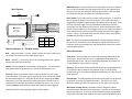
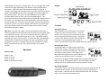
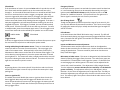
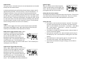
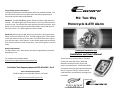
Programming remote transmitters:
To program replacement remotes please follow the procedures below. The
unit will hold a maximum of 2 remote codes and when programming all
other older remote codes will be deleted.
Method 1: Turn On and Off the ignition 8 times and leave it ON and wait 2
seconds. The LED will glow solid. Press button 1 of the new remote control
to set the code. The LED will flash twice and the siren will chirp twice. Press
button 1 on the second remote and the LED will flash 4 times and the siren
will chirp 4 times. Turn Off the ignition to set the codes.
Encore
M1: Two-Way
Motorcycle & ATV Alarm
Method 2: With the ignition ON, press firmly and hold in the programming
button on the back of the main unit. The LED will glow solid. Press button 1
of the new remote control to set the code. The LED will flash twice and the
siren will chirp twice. Press button 1 on the second remote and the LED will
flash 4 times and the siren will chirp 4 times. Turn Off the ignition to set the
codes.
Battery Replacement:
The M1 remotes use a “AAA” Battery and will last approximately 4 months
depending on use.
Professional installation only
Installation and User’s Manual
For Customer service please email:
[email protected]
For Dealer Tech Support please call 855-463-6267: Ext 3
Encore Automotive Systems
27240 Turnberry Lane Suite 200, Valencia CA 91355
www.encoreautomotivesystems.com
The Encore M1 is a state of the art Two-way
motorcycle alarm that utilizes advanced
detection techniques to fully secure and
protect your Motorcycle. It offers both Radar
and impact sensing and incorporates advanced
Starter or Ignition shutoff. Please read and
understand this manual before you begin your
installation.
Powered By:
E
ncore
White Wires (2): The two white wires are the output for the turn indicators.
One is to be connected to the right positive side of the turn indicator and
the other is for the left. Both have positive outputs from a relay and both
are isolated so they will not affect turn indicator operation.
Wire Diagram:
Antenna
LED
RED: System Power
Encore
9 Pin
Learn Button
Blue: Horn Output
Yellow: 12 Volt ACC.
Violet: Kill OUTPUT
Violet: Kill INPUT
White: Rt. Parking Light
Blue/Wht: Horn Input
White: Lt. Parking Light
M1 Two Way
Motorcycle Alarm
3 Pin
2 Pin
Black: System Ground
Locking Tab
3 Pin Connector
Radar Sensor
Siren
2 Pin Connector
Black
Red
Violet
Blue/Wht
Blue
Violet
Yellow
White
White
Connector Front View
Blue / White: This is the input for the horn of the motorcycle. It will allow
you to change the polarity of the horn output. If the motorcycles horn is
triggered by a negative or ground signal, connect this wire to ground. If the
horn has a positive trigger, this wire should be connected to a positive
power source or the red wire of this harness. Please check the horn when
the key is ON and determine if the trigger of the horn is positive or negative.
Once determined turn the key to the OFF position and insure the trigger is
correct. This wire is attached to the common post of a horn relay and will
be open when the horn is not used.
Blue: This is the horn output and will deliver the output polarity based on
the connection to the Blue / white wire above. Please install the siren as
most horn wires are accessible from the outside of the motorcycle and can
easily be disconnected.
Main wire Harness: 9 – Pin Main Harness
Other Connections:
Red: Main unit Power, + 12 Volt. Please connect this wire to constant 12
volt Power at the battery or any stable power source.
Black: Ground (-). Connect this wire to any stable ground or the negative
battery terminal of the motorcycle.
Yellow: This wire should be connected to 12 Volt Ignition. This wire should
have power when the Ignition Key is in the ON or RUN position only.
Violet (2): These wires are the starter or ignition cutoff. They are a relay
input and output. The starter wire or Ignition wire of the motorcycle should
be confirmed and then cut. Both sides of the cut wire should go to either
violet wires. One is the input and the other the output. Either wire can be
used but both need to be connected to complete the circuit. This circuit is
normally closed and will disconnect when the system has been triggered.
Please use caution if interrupting the ignition of the vehicle.
Siren wires: The siren plugs into the two pin connector dedicated for the
siren output. Please secure the siren in a good place facing down and
attach with two screws. This siren has double sided tape on the back but
screws should be used to secure it in place.
Antenna: The antenna should be mounted away from surrounding metal in
an area that is open to allow for the greatest range. It can be placed
beneath fairings or in any area including the handle bars, tail, side covers or
under the seat.
LED Indicator: The LED should be mounted in an area where it can be seen
by the rider as well as any unwanted intruder. This will act as a visual
deterrent and will give the rider notification of the status of the system.
Microwave or Radar Sensor: The Radar sensor is designed to detect
movement above and around the motorcycle. It connects to the three pin
plug on the main unit. This sensor will penetrate all surfaces except metal.
It should be mounted in the middle of the motorcycle facing UP and can be
installed under the seat or in any open area. The unit will trigger warn away
as well as full trigger depending on the amount of time the disturbance
takes place. If the radar sensor sees movement within its range for 3
seconds, it will trigger the warn-away of the alarm with a few siren and horn
beeps. If the disturbance continues, it will trigger the primary trigger and
will sound the alarm. This sensor can be overridden by the remote in
situations where there are many motorcycles parked together. The
sensitivity of the sensor can be adjusted by turning the adjustment screw on
the sensor. Turn the adjustment screw Clockwise for more sensitivity and
counterclockwise less. The sensor will only trigger if motion is sustained for
more than 3 second. The circuit is design in this manner to minimize false
alarms and should not be used if there is always normal activity around
where the motorcycle is parked.
Main Unit: The main unit is water resistant and should be mounted in a
location that offers the best protection form the elements and is hard to get
to by a would be intruder. This can be mounted in the fairing, side cover,
under the tank or the tail of the motorcycle or ATV. It should be securely
mounted with screws if at all possible. The main unit does come with high
strength Velcro included but securing this unit will provide better results.
The impact 3 axis sensor is located in the main unit and will sense impact
better if secured with screws. Please plan and choose this location
carefully.
Operation:
Button Layout:
Button 1: Arm
Button 2: Disarm
Button 3: Locate
Button 4: Microwave ON- OFF
Display:
Functions:
Arming the System:
With the ignition in the OFF position, Press button
number 1 or Lock to Arm the system. The siren
and horn will chirp once if connected and the lights
on the motorcycle will flash one time. The system
is now armed. While armed, the LED will flash two
times every 2 seconds indicating the system is
armed. The remote will show a lock symbol when the system is armed.
Disarming the System:
By pressing button 2 or disarm on the remote you
will disarm the system. The lights will flash 2 times
and the siren and horn will chirp twice. The remote
will show an unlock symbol. If the motorcycle is
disarmed and the ignition is not turned ON within 30
seconds the unit will rearm itself. To stop this
process turn the ignition switch to ON or press the disarm button twice
within 1 second. If the ignition switch is not turned ON the unit will
interpret this as an accidental disarm and will rearm the system.
Not Armed Reminder:
If the ignition switch is turned off and the unit has not been armed within 20
seconds, the unit will alert the user by chirping 3 times and flashing the
lights 3 times. It will also alert the remote and the unlock icon will flash 3
times. The unit will not automatically arm.
Silent Mode:
If the Arm button or button 1 is pressed twice within 2 seconds the unit will
be in silent mode and the speaker icon on the remote will have a line
through it. In this mode the alarm will function as normal but will NOT honk
the horn or activate the siren when a trigger is recognized. When the
system is triggered by either warn-away or full trigger, the lights will flash
on the motorcycle but no audible alarm will be heard. The Remote will
make a sound and vibrate while showing what was triggered. If the warn –
away was triggered the unit will beep and vibrate showing the user what
triggered the system. If full trigger is initiated, the unit will add a melody
sound as well. All other functions of the unit will stay the same. To return
to audible mode, press the arm button again twice. This will toggle in and
out of silent mode and can be verified by the speaker icon on the remote.
Audible Mode
Silent Mode
Trigger Disarm:
If the unit is triggered press the Disarm button to disarm the system or press
the arm button to stop the siren and keep the system armed.
Arming and deleting the Microwave sensor: There are times when your
motorcycle will be in an area of constant activity. This may trigger your
radar or microwave sensor. When parked in areas close to activity the
Microwave or Radar sensor can be shut off to eliminate false triggers. This
can be done by pressing button 1 to arm the system and within 2 second
pressing button 4. The remote will make a melody sound and the siren will
chirp once indicating the radar sensor will be off. The sensor will turn ON
again the next time the system is armed.
Locate:
By pressing button 3 the motorcycle will chirp the horn and siren 3 times
and will flash the lights 3 times to help you locate the motorcycle in large
parking lots.
Starter or Ignition Kill:
If installed, the unit will disable the starter or ignition when the unit has
been triggered. Warn-away and full triggers will disable this circuit. If a
starter kill was wired on the motorcycle, during trigger the motorcycle will
not start. If an Ignition disable was connected, the motorcycle will not run
during trigger events.
Emergency Disarm:
In the event that the system is armed and the remote control has been lost
or is not functioning, the unit can be manually disarmed by turning the
ignition switch ON and OFF 10 times quickly and the key left in the ON
position for 3 additional seconds. The system will not arm again until a
disarm signal is receive by the unit from any transmitter.
Out of Range Check:
Though the M1 Motorcycle alarm system has range of up to one mile, this
can vary with different environmental conditions. If the unit is out of range
for paging the remote will play a melody sound and the signal strength bar
will be at no bars.
LED Indicator:
In the armed status the LED will blink twice every 2 seconds. The LED will
flash continuously during any trigger event and if triggered will flash 4 times
every 2 seconds until the ignition is turned ON. This indicates the alarm was
triggered while armed.
Impact and Microwave sensor adjustment:
The Microwave sensor and the impact sensor both can be adjusted to
obtain the best sensitivity for the motorcycle. Caution should be used in the
setting of these devises. The more sensitivity each sensor has the more
likely it will false trigger.
Microwave or Radar sensor: This sensor is designed to help eliminate false
alarms by filtering the triggers from the sensor. The radar sensor must see
movement for 3 second before it will trigger the system. If a leaf falls from
an overhanging tree it will be ignored. The sensor can be adjusted at the
sensor with a small screwdriver. The adjustment is fairly straight forward.
Turn the adjustment counter clockwise for less sensitivity and clockwise for
greater sensitivity. The adjustment will only turn 100 degree in either
direction. Do not force the adjustment past its physical stops. The LED just
above the adjustment port will light every time the unit sees motion of any
kind. This will only light if the system is armed and the radar sensor has not
been deleted.
Impact Sensor:
The impact sensor is located in the main unit and adjustments can be made
directly from the remote control.
In the disarmed mode press and hold the disarm button or button two for
approximately 4 seconds. The unit will chirp. Press the Arm button, 1, to
change the sensitivity. There are 5 levels of sensitivity and the factory
setting is 3. Level 1 is the highest sensitivity and level 5 is the lowest. Press
the Arm button and the unit will respond with one chirp. Press again and it
will be set to level 2. Two chirps will be heard. Press again for level 3, 4 and
5 in the same manner. Once the desired setting is achieved, press and hold
the disarm button or button 2 until a long chirp is heard. This will indicate
that the setting has been set into the unit’s memory.
Triggers:
There are three trigger points for the system with the impact and Radar
having warn-away trigger as well. Warn away will give notice that your
motorcycle is armed when a small disturbance is sensed.
Radar Sensor Trigger with warn-away. When
movement is sensed for three seconds the
radar sensor will trigger the warn-away and
the unit will chirp three times. If the
disturbance continues, the unit will go into
full trigger mode. The remote will vibrate and
make a melody noise. The LCD indicator will
alert you that the trigger was from the radar sensor. This is shown by the
rotating box in the clock area.
Impact Sensor Trigger with warn-away:
When a slight impact is felt by the sensor for 2
seconds, the unit will trigger the warn-away
and the unit will chirp three times. If the
disturbance continues, the unit will go into
full trigger mode. The remote will vibrate and
make a melody noise. The LCD indicator will
alert you that the trigger was from the Impact
sensor. This is shown by the remote pictured here.
Ignition Trigger:
When the system is armed and the ignition
switch is turned ON the unit will trigger a full
event. The siren and horn will sound and the
parking lights will flash for 30 seconds.
Setting the time on the remotes:
The remotes have both the time and an alarm timer function. These can be
set to show the time of day as well as an alarm time. They are in 24 hour
military time as there are no AM or PM capabilities in the remote.
Setting the Time:
• Press button 1 and 2 at the same time for 2 seconds. The remote
will make a tone and the lock icon will flash. Then press the Arm
button to select between, time minutes….time hours…..alarm ON or
Off……alarm minutes…….alarm hours……and exit. The selected
characters will flash rapidly.
• Press button 2 to adjust the flashing characters and press button 1
to move to the next segment.
• Once the time and alarm is set. Move the display until the top of
the display says “set” or exit and there is nothing else in the clock
position
• Press both button 1 and 2 together again for 2 seconds until the
unit reacts with a sound. Your values have been set.
• If you wish to exit without saving the settings, press the disarm
button to exit.