1
38YDA
Two-Speed Split-System Heat Pump
Visit www.carrier.com
Installation and Start-Up Instructions
NOTE: Read the entire instruction manual before starting the
installation.
This symbol → indicates a change since the last issue.
SAFETY CONSIDERATIONS
Improper installation, adjustment, alteration, service, maintenance,
or use can cause explosion, fire, electrical shock, or other
conditions which may cause death, personal injury, or property
damage. Consult a qualified installer, service agency, or your
distributor or branch for information or assistance. The qualified
installer or agency must use factory-authorized kits or accessories
when modifying this product. Refer to the individual instructions
packaged with the kits or accessories when installing.
Follow all safety codes. Wear safety glasses, protective clothing,
and work gloves. Use quenching cloth for brazing operations.
Have fire extinguisher available. Read these instructions thoroughly and follow all warnings or cautions included in literature
and attached to the unit. Consult local building codes and National
Electrical Code (NEC) for special requirements.
Recognize safety information. This is the safety-alert symbol
.
When you see this symbol on the unit and in instructions or
manuals, be alert to the potential for personal injury.
Understand the signal words DANGER, WARNING, and CAUTION. These words are used with the safety-alert symbol. DANGER identifies the most serious hazards which will result in severe
personal injury or death. WARNING signifies hazards which
could result in personal injury or death. CAUTION is used to
identify unsafe practices which would result in minor personal
injury or product and property damage.
Before installing, modifying, or servicing system, main electrical disconnect switch must be in the OFF position. There
may be more than 1 disconnect switch. Lock out and tag
switch with a suitable warning label. Electrical shock can
cause personal injury or death.
INSTALLATION RECOMMENDATIONS
NOTE: In some cases noise in the living area has been traced to
gas pulsations from improper installation of equipment.
1. Locate unit away from windows, patios, decks, etc. where unit
operation sound may disturb customer.
2. Ensure that vapor and liquid tube diameters are appropriate to
capacity of unit.
3. Run refrigerant tubes as directly as possible by avoiding
unnecessary turns and bends.
4. Leave some slack between structure and unit to absorb
vibration.
5. When passing refrigerant tubes through the wall, seal opening
with RTV or other pliable silicon-based caulk. (See Fig. 2.)
6. Avoid direct tubing contact with water pipes, duct work, floor
joists, wall studs, floors, and walls.
A98516
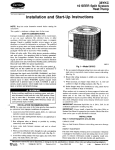
Fig. 1—Model 38YDA
7. Do not suspend refrigerant tubing from joists and studs with a
rigid wire or strap which comes in direct contact with tubing.
(See Fig. 2.)
8. Ensure that tubing insulation is pliable and completely surrounds vapor tube.
9. When necessary, use hanger straps which are 1 in. wide and
conform to shape of tubing insulation. (See Fig. 2.)
10. Isolate hanger straps from insulation by using metal sleeves
bent to conform to shape of insulation.
When outdoor unit is connected to factory-approved indoor unit,
outdoor unit contains system refrigerant charge for operation with
indoor unit of the same size when connected by 15 ft of
field-supplied or factory accessory tubing. For proper unit operation, check refrigerant charge using charging information located
on control box cover or in the Check Charge section of this
instruction.
IMPORTANT: Maximum liquid-line size is 3/8-in. OD for all
residential applications.
IMPORTANT: Always install a liquid-line filter drier. Refer to
Product Data Digest for appropriate part number. Obtain filter
driers from your distributor or branch.
INSTALLATION
Step 1—Check Equipment and Job Site
UNPACK UNIT
Move to final location. Remove carton taking care not to damage
unit.
INSPECT EQUIPMENT
File claim with shipping company prior to installation if shipment
is damaged or incomplete. Locate unit rating plate on unit corner
Manufacturer reserves the right to discontinue, or change at any time, specifications or designs without notice and without incurring obligations.
Book 1 4
PC 101
Catalog No. 563-717
Printed in U.S.A.
Form 38YDA-2SI
Pg 1
11-98
Replaces: 38YDA1SI
Tab 5a 5a
On rooftop applications, mount on level platform or frame. Place
unit above a load-bearing wall and isolate unit and tubing set from
structure. Arrange supporting members to adequately support unit
and minimize transmission of vibration to building. Consult local
codes governing rooftop applications.
NOTE: Unit must be level to within ± 2° (± 3/8 in./ft) per
compressor manufacturer specifications.
NOTE: Avoid contact between tubing and structure
OUTDOOR WALL
INDOOR WALL
CAULK
LIQUID TUBE
Step 3—Clearance Requirements
When installing, allow sufficient space for airflow clearance,
wiring, refrigerant piping, and service. Allow 30-in. clearance to
service end of unit and 48 in. above unit. For proper airflow, a 6-in.
clearance on 1 side of unit and 12 in. on all remaining sides must
be maintained. Maintain a distance of 24 in. between units.
Position so water, snow, or ice from roof or eaves cannot fall
directly on unit.
VAPOR TUBE
INSULATION
THROUGH THE WALL
JOIST
HANGER STRAP
(AROUND VAPOR
TUBE ONLY)
On rooftop applications, locate unit at least 6 in. above roof
surface.
INSULATION
VAPOR TUBE
Step 4—Operating Ambients
The minimum outdoor operating ambient in cooling mode is 55°F,
and the maximum outdoor operating ambient in cooling mode is
125°F. The maximum outdoor operating ambient in heating mode
is 66°F.
1″ MIN.
Step 5—Elevate Unit
LIQUID TUBE
SUSPENSION
Accumulation of water and ice in base pan may cause
equipment damage.
A94028
Fig. 2—Connecting Tubing Installation
Elevate unit per local climate and code requirements to provide
clearance above estimated snowfall level and ensure adequate
drainage of unit. Fig. 4 shows unit with accessory support feet
installed. Use accessory snow stand in areas where prolonged
freezing temperatures are encountered. Refer to separate Installation Instructions packaged with accessories.
panel. It contains information needed to properly install unit.
Check rating plate to be sure unit matches job specifications.
Step 2—Install on a Solid, Level Mounting Pad
If conditions or local codes require the unit be attached to pad, tie
down bolts should be used and fastened through knockouts
provided in unit base pan. Refer to unit mounting pattern in Fig. 3
to determine base pan size and knockout hole location.
3/8-IN. DIA TIEDOWN
KNOCKOUTS IN BASEPAN
(2) PLACES
C
L
A
B
A98533
8 3/16 ″
VIEW FROM TOP
Fig. 4—Accessory Support Feet
Step 6—Remove Indoor AccuRater® Piston and Replace
with TXV
NOTE: If indoor unit is not equipped with a TXV, use an
accessory indoor thermostatic expansion valve (TXV) when required. Refer to presale literature for proper Part No.
A97548
Dimensions (In.)
UNIT
SIZE
MINIMUM
MOUNTING PAD
DIMENSIONS
036, 048, 060
26 X 32
TIEDOWN KNOCKOUT
LOCATIONS
A
B
5-1/16
9-11/16
FURNACE COILS
Remove existing AccuRater from indoor coil and install required
accessory TXV kit. (See Fig. 5.)
Fig. 3—Mounting Unit to Pad
Install TXV kit to indoor coil as follows:
2
To prevent compressor damage DO NOT bury more than 36
in. of refrigerant tubing. If ANY tubing is buried, provide
6-in. vertical rise at service valve.
COIL
SENSING
BULB
Outdoor units may be connected to indoor section using accessory
tubing package or field-supplied refrigerant grade tubing of correct
size and condition. Tubing diameters listed in Table 1 are adequate
for equivalent lengths up to 100 ft. DO NOT INSTALL EQUIVALENT INTERCONNECTING TUBING LENGTHS GREATER
THAN 100 FT. Do not increase or decrease interconnecting tubing
diameters.
EQUALIZER
TUBE
THERMOSTATIC
EXPANSION
VALVE
Table 1—Refrigerant Connections and
Recommended Liquid and Vapor Tube
Diameters (In.)
A91277
Fig. 5—TXV Installed
UNIT
SIZE
1. Install suction tube adapter.
036, 048
060
2. Install liquid flare-to-sweat adapter.
3. Install TXV on liquid flare-to-sweat adapter.
LIQUID
Connection
Tube
Diameter
Diameter
3/8
3/8
3/8
3/8
VAPOR
Connection
Tube
Diameter
Diameter
7/8
7/8
7/8
1-1/8
NOTES:
1. Tube diameters are for lengths up to 100 equivalent ft.
2. Do not increase or decrease tubing sizes.
4. Connect external equalizer tube to fitting on suction tube
adapter.
5. Position sensing bulb on horizontal portion of suction tube
adapter. Secure using supplied hardware. Insulate bulb after
installation. (See Fig. 6.)
If refrigerant tubes or indoor coil are exposed to atmosphere, they
must be evacuated to 500 microns to eliminate contamination and
moisture in the system.
6. Check all connections for leaks.
OUTDOOR UNIT CONNECTED TO FACTORY-APPROVED
INDOOR UNIT
10 O'CLOCK
2 O'CLOCK
See Product Data Sheet for factory-approved indoor units.
Outdoor unit contains correct system refrigerant charge for operation with indoor unit of same size when connected by 15 ft of
field-supplied or factory-accessory tubing. Check refrigerant
charge for maximum efficiency.
SENSING BULB
STRAP
REFRIGERANT TUBING
SUCTION TUBE
4 O'CLOCK
8 O'CLOCK
7⁄8
IN. OD & SMALLER
Connect tubing to fittings on outdoor unit vapor and liquid service
valves. (See Table 1.) Use refrigerant grade tubing.
LARGER THAN
7⁄8
SWEAT CONNECTION
IN. OD
A81032
Fig. 6—Positioning of Sensing Bulb
To prevent damage to unit or service valves observe the
following:
• Use a brazing shield.
• Wrap service valves with wet cloth or use a heat sink
material.
FAN COILS
If unit is installed with an 40FKA, FK4 or FC4 fan coil, no TXV
change is necessary since these fan coils are factory-equipped with
proper TXV.
Service valves are closed from factory and ready for brazing. After
wrapping service valve with a wet cloth, tubing set can be brazed
to service valve using either silver bearing or non-silver bearing
brazing material. Consult local code requirements. Refrigerant
tubing and indoor coil are now ready for leak testing. This check
should include all field and factory joints.
If TXV installation is required, refer to TXV kit Installation
Instructions for details on TXV installation.
Step 7—Make Piping Connections
FINAL TUBING CHECK
IMPORTANT: Check to be certain factory tubing on both indoor
and outdoor unit has not shifted during shipment. Ensure tubes are
not rubbing against each other or any sheet metal. Pay close
attention to feeder tubes, making sure wire ties on feeder tubes are
secure and tight.
Relieve pressure and recover all refrigerant before system
repair or final unit disposal to avoid personal injury or death.
Use all service ports and open all flow-control devices,
including solenoid valves.
3
Step 8—Make Electrical Connections
The outdoor unit requires a minimum of 27-va, 24-vac control
power.
FINAL WIRING CHECK
To avoid personal injury or death, do not supply power to unit
with compressor terminal box cover removed.
IMPORTANT: Check factory wiring and wire connections to
ensure terminations are secured properly. Check wire routing to
ensure wires are not in contact with tubing, sheet metal, etc.
Be sure field wiring complies with local and national fire, safety,
and electrical codes, and voltage to system is within limits shown
on unit rating plate. Contact local power company for correction of
improper voltage. See unit rating plate for recommended circuit
protection device.
Step 9—Install Electrical Accessories
GENERAL
Refer to the individual instructions packaged with kits or accessories when installing.
NOTE: Operation of unit on improper line voltage constitutes
abuse and could affect unit reliability. See unit rating plate. Do not
install unit in system where voltage may fluctuate above or below
permissible limits.
Low-ambient kits are not available for 2-speed units. Do not
attempt to operate unit below 55°F in cooling mode or modify
control system for low-ambient operation. Compressor damage may occur.
NOTE: Use copper wire only between disconnect switch and
unit.
NOTE: Install branch circuit disconnect of adequate size per
NEC to handle unit starting current. Locate disconnect within sight
from and readily accessible from unit, per Section 440-14 of NEC.
Available electrical accessories include latent capacity control. See
Table 2 and Fig. 8 for typical accessory wiring diagrams.
ROUTE GROUND AND POWER WIRES
LATENT CAPACITY CONTROL (LCC)
Remove access panel and control box cover to gain access to unit
wiring. Extend wires from disconnect through power wiring hole
provided and into unit control box. Size wires per NEC but not
smaller than minimum wire size shown in Product Data Sheet.
The purpose of an LCC is to provide a dehumidification mode to
assure a 75 percent or less system sensible heat ratio. If indoor unit
installed contains an ICM blower (such as an FK4C fan coil or a
58UHV,58UXV or 58MVP gas furnace), no LCC is required.
Indoor products with ICM blowers have enough CFM range to
provide proper airflow for low-speed cooling. If indoor unit
installed has a standard PSC blower motor, the low-speed airflow
available is too great to assure 75 percent or less system sensible
heat ratio. The LCC for standard blower products consists of a
standard humidistat which opens contacts on humidity rise and a
pilot duty relay with 24-v coil.
The unit cabinet must have an uninterrupted or unbroken
ground to minimize personal injury if an electrical fault
should occur. The ground may consist of electrical wire or
metal conduit when installed in accordance with existing
electrical codes. Failure to follow this warning can result in an
electric shock, fire, or death.
NOTE: If an LCC is desired, low-speed airflow must be maintained so that a minimum of 300 CFM/ton can be supplied during
high-speed LCC operation.
CONNECT GROUND AND POWER WIRES
Connect ground wire to ground connection in control box for
safety. Connect power wiring to leads provided as shown in Fig. 7.
LCC Operation for Typical PSC Fan Coils
The standard blower operation for systems with typical PSC fan
coils is covered in Fig. 8A, B, and D. The blower runs in high
speed regardless if compressor operation is high or low speed.
When the LCC is wired according to Fig. 8A, B, or D and humidity
rises, the humidistat contacts open and de-energize the relay. If
relay is de-energized, the system operates on high-speed compressor and high-speed airflow until humidistat closes. Fig. 8C shows
the wiring with a Carrier Thermidistat Control which controls
temperature and humidity level without the need for an additional
humidistat and relay.
DISCONNECT
PER N. E. C. AND/ OR
LOCAL CODES
CONTACTOR
FIELD POWER
WIRING
LCC Operation for Typical PSC Furnaces
FIELD GROUND
WIRING
The standard blower operation of systems with typical PSC
furnaces is covered in Fig. 8J, K, N, P, Q, or S. The blower runs
in high or low speed in conjunction with compressor high- or
low-speed operation. When the LCC is wired according to Fig. 8J,
K, N, P, Q, or S and humidity rises, the humidistat contacts open
and de-energize the relay. If relay is de-energized, the system
operates on high-speed compressor and low-speed airflow until
humidistat closes. Fig. 8L and R shows the wiring with a Carrier
Thermidistat Control which controls temperature and humidity
level without the need for an additional humidistat and relay.
GROUND
LUG
A91306
Fig. 7—Line Power Connections
CONNECT CONTROL WIRING
Route 24-v control wires through control wiring grommet and
connect to leads provided in control box. (See Table 2 and Fig. 8.)
Use No. 18 AWG color-coded, insulated (35°C minimum) wire. If
thermostat is located more than 100 ft from unit, as measured
along the control voltage wires, use No. 16 AWG color-coded wire
to avoid excessive voltage drop.
Step 10—Make Airflow Selections
AIRFLOW SELECTION FOR 58UHV,58UXV FURNACES
All wiring must be NEC Class 1 and must be separated from
incoming power leads.
The 58UHV,58UXV Non-Condensing Variable-Speed Furnaces
provide high- and low-speed blower operation to match the
4
Table 2—Wiring Diagram Reference
INDOOR PRODUCT
THERMOSTAT
Carrier Programmable (Model 2S)
Carrier Non-Programmable (Model 2S)
Standard Fan Coil
Carrier Thermidistat™ Control (Model RH)
Other Brand Models
Carrier Programmable (Model 2S)
Carrier Non-Programmable (Model 2S)
FK4C Fan Coil
Carrier Thermidistat™ Control (Model RH)
Other Brand Models
Carrier Programmable (Model 2S)
Carrier Non-Programmable (Model 2S)
Carrier Thermidistat™ Control (Model RH)
Single-Stage Furnace
Carrier Dual Fuel Thermostat (Model DF)
Other Brand Models
Carrier Programmable (Model 2S)
Carrier Non-Programmable (Model 2S)
Carrier Dual Fuel Thermostat (Model DF)
Two-Stage Furnace with PSC Blower Motor
Carrier Thermidistat™ Control (Model RH)
Other Brand Models
Carrier Programmable (Model 2S)
Carrier Non-Programmable (Model 2S)
Two-Stage Furnace with ICM Blower Motor
Carrier Dual Fuel Thermostat (Model DF)
Other Brand Models
Carrier Thermidistat™ Control (Model RH)
Variable-Speed 80% Non-Condensing Furnace
Carrier Dual Fuel Thermostat (Model DF)
Variable-Speed Condensing Furnace
Carrier Thermidistat™ Control (Model RH)
CONTROLS
Latent Capacity
Latent Capacity
Humidifier and Outdoor Sensor
Latent Capacity
—
—
Humidifier and Outdoor Sensor
—
Latent Capacity
Latent Capacity
Humidifier and Outdoor Sensor
Outdoor Sensor
Latent Capacity
Latent Capacity
Latent Capacity
Outdoor Sensor
Humidifier and Outdoor Sensor
Latent Capacity
—
—
Outdoor Sensor
—
Humidifier and Outdoor Sensor
Outdoor Sensor
Humidifier and Outdoor Sensor
DIAGRAM LETTER
IN FIG. 8
A
B
C
D
E
F
G
H
J
K
L
M
N
P
Q
V
R
S
T
U
V
W
X
Y
Z
Table 5.) This fan coil has an adjustable blower off delay factory
set at 90 sec for high- and low-speed blower operation.
capacities of compressor high and low speeds. To select recommended airflow, refer to Table 3 and the 58UHV,58UXV Installation Instructions. These settings are made on the furnace airflow
selector board by moving the appropriate color-coded jumper
wires. The ORANGE jumper wire should be set to the HP—EFFY
position for heat pump best efficiency or HP—CMFT for heat
pump enhanced comfort. The YELLOW COOL SIZE jumper is
used to select airflow to match the needed tons of cooling. The
BLUE CFM/TON jumper wire is used to select slight adjustments
to airflow of 400, 350, or 315 CFM per ton. (See Table 3.)
Step 11—Start-Up
To prevent compressor damage or personal injury, observe
the following:
• Do not overcharge system with refrigerant.
• Do not operate unit in a vacuum or at negative pressure.
• Do not disable low-pressure switch.
In scroll compressor applications:
• Dome temperatures may be hot.
AIRFLOW SELECTION FOR 58MVP FURNACES
The 58MVP Condensing Variable-Speed Furnaces provide highand low-speed blower operation to match the capacities of compressor at high and low speeds. To select recommended airflow,
refer to Table 4 and the 58MVP Installation Instructions. The
58MVP utilizes a control center that allows the installing technician to select proper airflows. For adjustments to the manual
switches labeled A/C and CF and recommended switch positions,
refer to Table 4. High-speed airflow is determined by the position
of the A/C switches, and low-speed airflow is determined by the
position of the CF switches. This furnace has a built-in, nonadjustable 90 sec off delay for cooling mode blower operation.
To prevent personal injury wear safety glasses, protective
clothing, and gloves when handling refrigerant and observe
the following:
• Back seating service valves are not equipped with Schrader
valves. Fully back seat (counter clockwise) valve stem before
removing gage port cap.
AIRFLOW SELECTION FOR FK4C OR 40FKA FAN COILS
The FK4C or 40FKA provides high- and low-speed blower
operation to match the capacities of compressor at high and low
speeds. To select recommended airflow, refer to Table 5 and the
FK4C or 40FKA Installation Instructions. The FK4C or 40FKA
utilizes an EASY SELECT control board that allows the installing
technician to select proper airflows. The ORANGE SYSTEM
TYPE jumper wire should be set to HP—EFF or
HP—COMFORT. The BLUE AC/HP SIZE JUMPER is used to
select airflow to match the outdoor unit nominal size in tons of
cooling. The BLACK AC/HP CFM ADJUST jumper is used to
make slight adjustments to the selected airflow tonnage. (See
Do not vent refrigerant to atmosphere. Recover during system
repair or final unit disposal.
Follow these steps to properly start up the system:
1. The outdoor unit is equipped with a crankcase heater which
operates at temperatures less than 75°F. If outdoor temperature is less than 75°F, energize crankcase heater 24 hr before
starting unit. To energize heater only, set indoor thermostat to
the OFF position and close power disconnect to the unit.
2. Fully back seat (open) liquid and vapor tube service valves.
5
CARRIER
NON-PROGRAMMABLE
THERMOSTAT
MODEL 2S
CARRIER
PROGRAMMABLE
THERMOSTAT
MODEL 2S
TYPICAL
FAN COIL
HEAT STAGE 3
W/W1
E
RVS COOLING
O/W2
W3
TWO-SPEED
HEAT PUMP
HEAT STAGE 3
TYPICAL
FAN COIL
E
W/W1
W2
W3
G
FAN
W2
FAN
COOL/HEAT
STAGE 2
Y2
G
Y1/W2
Y1
COOL/HEAT
STAGE 2
Y/Y2
Y2
24 VAC HOT
R
C
N/A
B
R
R
C
C
W3
24 VAC COMM
C
C
C
24 VAC HOT
R
R
R
RVS COOLING
O/W2
O
COOL/HEAT
STAGE 1
Y1
Y1
RVS HEATING
B
W3
OUTDOOR
S1
L
SENSOR
L
S1
OUTDOOR
G
O
COOL/HEAT
STAGE 1
24 VAC COMM
W2
Y/Y2
W2
G
TWO-SPEED
HEAT PUMP
CONNECTION
S2
See notes 7, 8, 10, and 11
SENSOR
See notes 7, 8, 9, and 11
S2
CONNECTION
H
H
A
B
R1
R1
A98581
A98580
CARRIER
THERMIDISTAT
CONTROL
MODEL RH
TYPICAL
FAN COIL
RVS COOLING O/W2
COOL/HEAT
STAGE 1
W3
HEAT STAGE 3 W/W1
W2
COOL/HEAT
STAGE 2
TWO-SPEED
HEAT PUMP
E
Y1/W2
OTHER BRAND
TWO-SPEED
THERMOSTAT
Y/Y2
TYPICAL
FAN COIL
24 VAC HOT
R
R
O
24 VAC COM
C
C
Y1
HEAT STAGE 3
W2
W2
W2
COOL/HEAT
STAGE 2
Y2
W3
Y2
FAN
G
G
EMERGENCY
HEAT
E
E
RVS COOLING
O
COOL/HEAT
STAGE 1
Y1
FAN
G
G
W3
24 VAC HOT
R
R
R
TWO-SPEED
HEAT PUMP
R
C
W2
Y2
W3
L
24 VAC COMM
N/A
HUMIDIFY
N/A
OUTDOOR
SENSOR
CONNECTION
C
C
C
O
Y1
DHUM
HUM
L
HUMIDIFIER
(24 VAC)
B
S1
See notes 8 and 11
OUTDOOR
SENSOR
H
S2
See notes 7, 8, 11, 16, and 17
R1
A98582
C
A97498
D
Fig. 8—Typical 24-v Circuit Connections
6
CARRIER
PROGRAMMABLE
THERMOSTAT
MODEL 2S
40FKA
FK4C
FAN COIL
CARRIER
NON-PROGRAMMABLE
THERMOSTAT
MODEL 2S
TWO-SPEED
HEAT PUMP
40FKA
FK4C
FAN COIL
TWO-SPEED
HEAT PUMP
DH
DH
J1 JUMPER
J1
JUMPER
24 VAC HOT
R
R
R
24 VAC COMM
C
C
C
FAN
G
G
Y/Y2
Y/Y2
24 VAC HOT
R
R
FAN
G
G
COOL/HEAT
STAGE 1
Y1/W2
Y1
Y1
RVS COOLING
O/W2
O
O
COOL/HEAT
STAGE 2
COOL/HEAT
STAGE 2
Y/Y2
Y/Y2
Y2
HEAT STAGE 3 W/W1
HEAT STAGE 3
W/W1
R
Y2
W1
W3
J2 JUMPER
W1
W2
W2
W2
J2 JUMPER
24 VAC COMM
C
N/A
B
OUTDOOR
SENSOR
CONNECTION
S1
W2
W3
C
C
RVS COOLING
O/W2
O
O
COOL/HEAT
STAGE 1
Y1
Y1
Y1
N/A
B
OUTDOOR
S1
L
See notes 7, 8, 9, 11, and 23
L
SENSOR
S2
CONNECTION
See notes 7, 8 ,10, 11 and 23
S2
A98583
E
CARRIER
THERMIDISTAT
CONTROL
MODEL RH
A98584
F
40FKA
FK4C
FAN COIL
TWO-SPEED
HEAT PUMP
RVS COOLING O/W2
O
O
COOL/HEAT
STAGE 1
Y1/W2
Y1
Y1
HEAT STAGE 3 W/W1
W1
COOL/HEAT
STAGE 2
W2
W2
FAN
G
Y/Y2
24 VAC HOT
R
G
J1 JUMPER
Y2
REMOVE J1
HUMIDIFY
N/A
OUTDOOR
SENSOR
CONNECTION
DHUM
DH
W3
C
C
C
HUM
24 VAC HOT
R
R
R
24 VAC COM
C
C
C
FAN
G
G
COOL/HEAT
STAGE 2
Y2
Y/Y2
HEAT STAGE 3
W2
W1
EMERGENCY
HEAT
E
W2
RVS COOLING
O
O
O
COOL/HEAT
STAGE 1
Y1
Y1
Y1
R
R
24 VAC COMM
Y2
J2 JUMPER
HUMIDIFIER
(24 VAC)
B
S1
TWO-SPEED
HEAT PUMP
DH
J2 JUMPER
Y/Y2
DEHUMIDIFY
40FKA
FK4C
FAN COIL
OTHER BRAND
TWO-SPEED
THERMOSTAT
OUTDOOR
SENSOR
S2
W3
See notes 8, 11, and 23
See notes 7, 8, 11, 13, 16, 17, and 23
W2
A98585
L
A98628
G
H
Fig. 8—Typical 24-v Circuit Connections (Continued)
7
CARRIER
PROGRAMMABLE
THERMOSTAT
MODEL 2S
COOL/HEAT
STAGE 1
SINGLE-STAGE
FURNACE
Y1/W2
Y1
G
G
HEAT STAGE 3
W/W1
W
COOL/HEAT
STAGE 2
Y/Y2
RVS COOLING
O/W2
FAN
CARRIER
NON-PROGRAMMABLE
THERMOSTAT
MODEL 2S
TWO-SPEED
HEAT PUMP
R
R
R
C
24 VAC COMM
C
C
HEAT STAGE 3
W/W1
W
Y2
COOL/HEAT
STAGE 2
Y/Y2
O
FAN
24 VAC HOT
R
24 VAC COMM
C
C
C
N/A
B
Y
W3
OUTDOOR
S1
R
TWO-SPEED
HEAT PUMP
24 VAC HOT
W2
R
Y2
G
G
W3
Y
RVS COOLING
L
O/W2
O
COOL/HEAT
STAGE 1
Y1
Y1
N/A
B
OUTDOOR
S1
SENSOR
CONNECTION
SINGLE-STAGE
FURNACE
S2
L
SENSOR
See notes 7, 9, 11,14 and 24
CONNECTION
S2
See notes 7, 10, 11, 14 and 24
H
H
R1
R1
A98586
A98587
J
K
Fig. 8—Typical 24-v Circuit Connections (Continued)
8
CARRIER
THERMIDISTAT
CONTROL
MODEL RH
CARRIER
PROGRAMMABLE
DUAL FUEL
THERMOSTAT
MODEL DF
TWO-SPEED
HEAT PUMP
SINGLE-STAGE
FURNACE
RVS COOLING O/W2
O
COOL/HEAT
STAGE 1
Y1
Y1/W2
HEAT STAGE 3 W/W1
W
W2
COOL/HEAT
STAGE 2
Y
Y2
SINGLE-STAGE
FURNACE
FAN
G
G
W3
24 VAC HOT
R
R
R
R
24 VAC HOT
R
R
FAN
G
G
W/ W1
W
W2
Y/ Y2
Y
Y2
HEAT STAGE 3
(FURNACE)
Y/Y2
TWO-SPEED
HEAT PUMP
COOL/HEAT
STAGE 2
(COMPRESSOR HI)
RVS COOLING
O/W2
O
COOL/HEAT
STAGE 1
Y1/W2
Y1
(COMPRESSOR LO)
W3
24 VAC COMM
N/A
HUMIDIFY
N/A
OUTDOOR
SENSOR
CONNECTION
C
C
C
24 VAC COM
C
N/A
B
RVS SENSING
L
OUTDOOR
SENSOR
CONNECTIONS
S1
C
C
DHUM
HUM
HUMIDIFIER
(24 VAC)
B
S1
OUTDOOR
SENSOR
S2
OUTDOOR
SENSOR
S2
See notes 7, 11, 14, 15, and 26
See notes 7, 11, 14, 15, 16, 17, 18 and 25
A98589
M
A98588
L
OTHER BRAND
TWO-SPEED
THERMOSTAT
SINGLE-STAGE
FURNACE
TWO-SPEED
HEAT PUMP
24 VAC HOT
R
R
R
24 VAC COM
C
C
C
HEAT STAGE 3
W2
W
W2
COOL/HEAT
STAGE 2
Y2
Y2
FAN
G
G
EMERGENCY
HEAT
E
Y
RVS COOLING
O
O
COOL/HEAT
STAGE 1
Y1
Y1
W3
L
H
See notes 11, 14, and 24
R1
A97495
N
Fig. 8—Typical 24-v Circuit Connections (Continued)
9
CARRIER
PROGRAMMABLE
THERMOSTAT
MODEL 2S
COOL/HEAT
STAGE 1
FAN
TWO-STAGE
FURNACE WITH PSC TWO-SPEED
BLOWER MOTOR
HEAT PUMP
Y1 *
Y1/W2
Y1
G
G
HEAT STAGE 3
W/W1
W/W1
COOL/HEAT
STAGE 2
Y/Y2
Y2
RVS COOLING
O/W2
O
24 VAC HOT
CARRIER
NON-PROGRAMMABLE
THERMOSTAT
MODEL 2S
R
R
24 VAC COMM
C
C
C
W/W1
W2
COOL/HEAT
STAGE 2
R
Y/Y2
Y2
G
G
W2
R
RVS COOLING
24 VAC COMM
C
C
C
N/A
B
Y/Y2
W3
L
S1
W3
Y/Y2
W2
OUTDOOR
SENSOR
CONNECTION
R
HEAT STAGE 3 W/W1
W2
TWO-SPEED
HEAT PUMP
24 VAC HOT
FAN
R
TWO-STAGE
FURNACE WITH PSC
BLOWER MOTOR
O
O/W2
COOL/HEAT
STAGE 1
Y1
N/A
B
OUTDOOR
S1
Y1 *
Y1
L
SENSOR
S2
CONNECTION
S2
See notes 6, 7, 10, 11, 12,
14, 21, and 24
See notes 6, 7, 9, 11, 12,
14, 21, and 24
H
H
P
Q
R1
R1
A98591
A98590
CARRIER
THERMIDISTAT
CONTROL
MODEL RH
RVS COOLING
O/W2
COOL/HEAT
STAGE 1
Y1/W2
TWO-STAGE
FURNACE
WITH PSC
BLOWER MOTOR
OTHER BRAND
TWO-SPEED
THERMOSTAT
*
Y1
HEAT STAGE 3 W/W1
W/W1
W2
COOL/HEAT
STAGE 2
Y/Y2
Y/Y2
Y2
FAN
G
G
24 VAC HOT
R
R
R
24 VAC HOT
R
R
R
24 VAC COM
C
C
C
HEAT STAGE 3
W2
W/W1
W2
COOL/HEAT
STAGE 2
Y2
FAN
G
G
EMERGENCY
HEAT
E
Y/Y2
RVS COOLING
O
W2
N/A
HUMIDIFY
N/A
OUTDOOR
SENSOR
CONNECTION
C
C
C
COOL/HEAT
STAGE 1
Y1
Y1
Y2
W3
O
W2
24 VAC COMM
TWO-SPEED
HEAT PUMP
TWO-SPEED
HEAT PUMP
O
Y1
TWO-STAGE
FURNACE WITH PSC
BLOWER MOTOR
*
Y1
DHUM
L
HUM
HUMIDIFIER
(24 VAC)
B
S1
See notes 6, 11, 12, 14, 21, and 24
OUTDOOR
SENSOR
H
S2
See notes 7, 11, 12, 14, 15, 16,
17, 18, 21, and 25
A98592
R1
R
S
A97497
Fig. 8—Typical 24-v Circuit Connections (Continued)
10
CARRIER
PROGRAMMABLE
THERMOSTAT
MODEL 2S
COOL/HEAT
STAGE 1
TWO-STAGE
VARIABLE-SPEED
FURNACE WITH ICM
BLOWER MOTOR
CARRIER
NON-PROGRAMMABLE
THERMOSTAT
MODEL 2S
TWO-SPEED
HEAT PUMP
Y1
G
G
HEAT STAGE 3
W/W1
W/W1
W2
COOL/HEAT
STAGE 2
Y/Y2
Y/Y2
Y2
RVS COOLING
O/W2
24 VAC HOT
R
24 VAC COMM
C
N/A
B
O
24 VAC HOT
R
R
R
24 VAC COMM
C
C
C
HEAT STAGE 3 W/W1
W/W1
W2
COOL/HEAT
STAGE 2
Y/Y2
Y/Y2
Y2
G
G
FAN
R
R
W2
OUTDOOR
W3
W2
C
C
RVS COOLING
W3
L
S1
O
O/W2
COOL/HEAT
STAGE 1
Y1
N/A
B
OUTDOOR
S1
Y1 *
SENSOR
CONNECTION
TWO-SPEED
HEAT PUMP
Y1 *
Y1/W2
FAN
TWO-STAGE
VARIABLE-SPEED
FURNACE WITH ICM
BLOWER MOTOR
S2
Y1
L
SENSOR
CONNECTION
See notes 6, 7, 9, 11, 12, 14, 21 and 24
S2
See notes 6, 7, 10, 11,12, 14, 21, and 24
A98593
A98594
T
CARRIER
PROGRAMMABLE
DUAL FUEL
THERMOSTAT
MODEL DF
U
TWO-STAGE
OR VARIABLE
SPEED FURNACE
TWO-SPEED
HEAT PUMP
R
24 VAC HOT
R
R
FAN
G
G
W/ W1
W/ W1
W2
Y/ Y2
Y/ Y2
Y2
HEAT STAGE 3
OTHER BRAND
TWO-SPEED
THERMOSTAT
TWO-STAGE
VARIABLE-SPEED
FURNACE WITH ICM
BLOWER MOTOR
TWO-SPEED
HEAT PUMP
(FURNACE)
COOL/HEAT
STAGE 2
24 VAC HOT
R
R
R
24 VAC COM
C
C
C
HEAT STAGE 3
W2
W/W1
W2
COOL/HEAT
STAGE 2
Y2
Y/Y2
Y2
FAN
G
G
W3
EMERGENCY
HEAT
E
W2
RVS COOLING
O
COOL/HEAT
STAGE 1
Y1
(COMPRESSOR HI)
RVS COOLING
O/W2
COOL/HEAT
STAGE 1
Y1/W2
O
Y1
*
Y1
(COMPRESSOR LO)
24 VAC COMM
C
N/A
B
RVS SENSING
L
OUTDOOR
SENSOR
CONNECTIONS
S1
W2
W3
C
C
OUTDOOR
SENSOR
O
Y1
*
Y1
L
S2
See notes 6, 7, 11, 12, 14, 21 and 24
See notes 7, 11, 12, 14, 15, 21 and 26
A98595
A97496
V
W
Fig. 8—Typical 24-v Circuit Connections (Continued)
11
VARIABLE SPEED 80%
NON-CONDENSING FURNACE
VARIABLE SPEED 80%
NON-CONDENSING FURNACE
CARRIER
THERMIDISTAT
CONTROL
MODEL RH
CARRIER
PROGRAMMABLE
DUAL FUEL
THERMOSTAT
MODEL DF
AFS
BOARD
O
Y1
TWO-SPEED
HEAT PUMP
RVS COOLING
O/W2
FURNACE
BOARD
O
HEAT/COOL
STAGE 1
Y1/W2
W2
Y1
HEAT STAGE 3
W/W1
W/W1
W2
HEAT/COOL
STAGE 2
Y/Y2
Y/Y2
Y2
FAN
G
G
W3
24 VAC HOT
R
R
R
24 VAC COM
C
COM
C
DEHUMIDIFY
DHUM
Y1
O/W2
FURNACE
BOARD
O
COOL/HEAT
STAGE 1
Y1/W2
W2
Y1
W/ W1
W/W1
W2
Y/ Y2
Y/Y2
Y2
FAN
G
G
W3
24 VAC HOT
R
R
R
24 VAC COMM
C
COM
C
N/A
B
RVS SENSING
L
(COMPRESSOR LO)
(FURNACE)
COOL/HEAT
STAGE 2
(COMPRESSOR HI)
HUM
DEHUM
HUM
DEHUM
PL9-10
PL9-10
HUM
N/A
B
OUTDOOR
SENSOR
CONNECTIONS
S1
TWO-SPEED
HEAT PUMP
RVS COOLING
HEAT STAGE 3
HUMIDIFY
AFS
BOARD
O
HUMIDIFIER
(24 VAC)
OUTDOOR
SENSOR
OUTDOOR
SENSOR
S1
OUTDOOR
SENSOR
CONNECTIONS
S2
See notes 7, 11, 12, 14, 15, 21, and 26
S2
A98597
See notes 7, 11, 12, 14, 15, 16, 17,
18, 20, 21, and 25
Y
A98596
X
CARRIER
THERMIDISTAT
CONTROL
MODEL RH
RVS COOLING
COOL/HEAT
STAGE 1
VARIABLE-SPEED
TWO-SPEED
CONDENSING
HEAT PUMP
FURNACE
O/W2
O
W2
Y1
Y1/W2
HEAT STAGE 3 W/W1
W/W1
W2
COOL/HEAT
STAGE 2
Y/Y2
Y/Y2
Y2
FAN
G
G
24 VAC HOT
R
R
R
DEHUMIDIFY
DHUM
DH
C
C
C
HUM
24 VAC COMM
HUMIDIFY
N/A
OUTDOOR
SENSOR
CONNECTION
HUM
HUMIDIFIER
(24 VAC)
B
OUTDOOR
SENSOR
S1
S2
See notes 7, 11, 12, 14, 15, 16, 17,
18, 19, 22, and 25
A98598
Z
Fig. 8—Typical 24-v Circuit Connections (Continued)
12
WIRING DIAGRAM NOTES:
1. Carrier thermostat wiring diagrams are only accurate for model numbers TSTAT _ _ _ _ _ _ _.
2. Wiring must conform to NEC or local codes.
3. Connect 24-v field wiring to factory-provided stripped leads.
4. Thermostats are factory configured with 5-minute compressor cycle protection and 4 cycles per hour limit. See thermostat Installation
Instructions for details.
5. To stage electric resistance heat, consult outdoor thermostat Installation Instructions.
6. Terminals marked with an * may not be present on equipment.
7. Underlined letter on dual terminal indicates its usage.
For example: O/W2 means O is energized in cooling mode.
8. Refer to fan coil Installation Instructions for features and additional wiring information.
9. Programmable model 2S, when used in heat pump installations (Switch C OFF), uses O/W2 to control reversing valve.
10. Non-programmable model 2S, when used in heat pump installations (Jumper R19 NOT cut), uses O/W2 to control reversing valve.
11. Select the ZONE position on 2-speed heat pump control board. In heating mode, this allows Y1 to control low-speed compressor
operation and Y2 to control high-speed compressor operation.
12. Furnace must control its own second-stage operation via furnace control algorithm. Refer to furnace Installation Instructions for proper
setup.
13. To activate dehumidify function on FK4C or 40FKA, remove J1 jumper at fan coil control board.
14. Heat pump MUST have a high-pressure switch for dual fuel applications.
15. Outdoor air temperature sensor must be attached in all dual fuel applications.
16. Thermidistat Dip Switch 1 should be set in the ON position for heat pump installations.
17. Thermidistat Dip Switch 2 should be set in the ON position for 2-speed compressor operation.
18. Thermidistat Configuration Option No. 10 "Dual Fuel Selection" must be turned on in all dual fuel applications.
19. To activate dehumidify feature on current style 58MVP variable-speed furnaces, a pilot duty, 24-v relay must be used.
20. To activate dehumidify feature on current style 58UHV,58UXV variable-speed 80% non-condensing furnaces, disconnect green
(dehum) wire from G on furnace control board and connect to dehumidify terminal dhu on thermidistat.
21. See Table 3—Airflow Selection for 58UHV,58UXV Furnaces.
22. See Table 4—Airflow Selection for 58MVP Furnaces.
23. See Table 5—Airflow Selection for FK4C or 40FKA Fan Coil.
24. Select Furnace Interface Option, Balance Point, and Defrost Time on 2-speed heat pump control board.
25. Thermidistat controls dual fuel operation; do not select Furnace Interface Option on 2-speed heat pump control board.
26. Dual fuel thermostat Dip Switch D should be set in the ON position for 2-speed compressor operation. This thermostat controls dual
fuel operation; do not select Furnace Interface Option on 2-speed heat pump control board.
LEGEND
24-V FACTORY WIRING
24-V FIELD WIRING
FIELD SPLICE CONNECTION
RELAY SPDT, PILOT DUTY
24-V COIL (HN61KK324)
OR EQUIVALENT
R1
H
AFS
HUMIDISTAT, OPENS ON
HUMIDITY RISE (HL38MG026)
AIRFLOW SELECTOR
A97466
13
Table 3—Airflow Selection for 58UHV,58UXV Furnaces (CFM)
38YDA
UNIT
SIZE
FURNACE
MODEL/HEATING
SIZE
Cool Size
Jumper
Position
060
HI
080
M-LO
100
LO
120
LO
080
HI
100
M-HI
120
M-HI
100
HI
120
HI
036
048
060
FURNACE AIRFLOW SELECTION BOARD SETTINGS
Cool CFM Per Ton Jumper Position
AC/HP
400
350
315
Jumper
Heat Pump Heating Airflow*
Position
High
Low
High
Low
High
Low
HP—EFFY
1260
780
1100
680
990
585
HP—CMFT
1135
700
990
610
895
555
HP—EFFY
1260
790
1100
700
990
625
HP—CMFT
1135
715
990
630
895
560
HP—EFFY
1260
780
1090
775
990
700
HP—CMFT
1130
700
980
700
890
700
HP—EFFY
1195
865
1085
785
985
785
HP—CMFT
1075
780
975
750
885
750
HP—EFFY
1635
1040
1470
915
1325
820
HP—CMFT
1510
940
1325
825
1190
740
HP—EFFY
1680
1040
1465
915
1325
820
HP—CMFT
1510
935
1320
825
1190
740
HP—EFFY
1650
1070
1465
975
1315
930
HP—CMFT
1485
965
1320
880
1185
835
HP—EFFY
2085
1300
1840
1150
1655
1025
HP—CMFT
1890
1170
1655
1035
1490
920
HP—EFFY
2110
1300
1865
1140
1640
1080
HP—CMFT
1900
1170
1650
1025
1475
970
* Heat Pump Cooling Airflow always matches HP—EFFY Heat Pump Heating Airflow.
Table 4—Airflow Selection for 58MVP Furnaces (CFM)
38YDA
UNIT
SIZE
036
048
060
HIGH-SPEED
A/C SETUP
SWITCH POSITION
A/C-1
A/C-2
A/C-3
OFF
OFF
ON
OFF
ON
ON
OFF
ON
ON
FURNACE MODEL/HEATING SIZE
060
High
1200
—
—
080
Low
800
—
—
High
1200
—
—
100
Low
800
—
—
High
1200
1600
1600*
Low
800
1000
1000
LOW-SPEED
CF SETUP
SWITCH POSITION
CF-1
CF-2
CF-3
OFF
ON
OFF
ON
ON
OFF
ON
ON
OFF
* Efficiency rating obtained at 1600 CFM. If 2000 CFM is desired, adjust airflow per 58MVP Installation Instructions.
Table 5—Airflow Selection for FK4C or 40FKA Fan Coils (CFM)
38YDA
UNIT
SIZE
FK4C
UNIT
SIZE
001
002
036
003
005
006
005
048
006
060
006
EASY SELECT CONTROL BOARD
AC/HP
AC/HP
SYSTEM TYPE
SIZE
CFM ADJUST
(Orange Wire)
(Blue Wire)
(Black Wire)
HP—EFF
036
NOM
HP—COMFORT
HP—EFF
036
NOM
HP—COMFORT
HP—EFF
036
NOM
HP—COMFORT
HP—EFF
036
NOM
HP—COMFORT
HP—EFF
036
NOM
HP—COMFORT
HP—EFF
048
NOM
HP—COMFORT
HP—EFF
048
NOM
HP—COMFORT
HP—EFF
060
NOM
HP—COMFORT
HEATING CFM*
High
Low
1100
990
1100
990
1100
990
1100
990
1100
990
1470
1320
1470
1325
1835
1655
680
615
680
615
680
615
680
615
745
670
910
820
995
895
1240
1120
COOLING CFM*
High
Low
1100
680
1100
680
1100
680
1100
680
1100
745
1470
910
1470
995
1835
1240
* Airflow CFMs are given with AC/HP CFM ADJUST jumper set at NOM. Airflow can be adjusted +15% or -10% by selecting HI or LO respectively.
14
Table 6—Required Liquid-Line Temperature (°F)
3. Unit is shipped with valve stem(s) front seated and caps
installed. Replace stem caps after system is opened to refrigerant flow (back seated). Replace caps finger tight and tighten
additional 1/12 turn (20 ft-lb torque) with wrench.
LIQUID
PRESSURE AT
SERVICE VALVE
(PSIG)
4. Close electrical disconnects to energize system.
134
141
148
156
163
171
179
187
196
205
214
223
233
243
253
264
274
285
297
309
321
331
346
359
5. Set room thermostat at desired temperature. Be sure the set
point is below indoor ambient and is set low enough to
energize desired speed.
NOTE: Carrier electronic thermostats are equipped with a 15minute staging timer. This timer prevents the 2-speed system from
operating at high speed until unit has been operating in low speed
for 15 minutes unless there is at least a 5°F difference between
room temperature and thermostat set point. To force high speed
(after a minimum of 2 minutes in low speed), adjust the set point
at least 5° below room ambient for cooling or 5° above room
ambient for heating.
6. Set room thermostat to COOL or HEAT and fan control to
AUTO or ON as desired. Wait for the appropriate time
delay(s) and the 2-minute minimum low-speed run time.
Operate unit for 15 minutes. Check refrigerant charge.
Step 12—Check Charge
Service valve gage ports are not equipped with Schrader
valves. To prevent personal injury, make sure gage manifold
is connected to the valve gage ports before moving valves off
fully back seated position. Wear safety glasses and gloves
when handling refrigerant.
5
71
74
77
80
83
86
89
92
95
98
101
104
107
110
113
116
119
122
125
128
131
134
137
140
REQUIRED SUBCOOLING
TEMPERATURE
(°F)
10
15
66
61
69
64
72
67
75
70
78
73
81
76
84
79
87
82
90
85
93
88
96
91
99
94
102
97
105
100
108
103
111
106
114
109
117
112
120
115
123
118
126
121
129
124
132
127
135
130
20
56
59
62
65
68
71
74
77
80
83
86
89
92
95
98
101
104
107
110
113
116
119
122
125
UNIT CHARGE
temperature do not match on chart, system refrigerant charge may
not be correct. Do not use chart to adjust refrigerant charge.
Factory charge is shown on unit rating plate. To check charge in
cooling mode, refer to Cooling Only Procedure. To check charge
in heating mode, refer to Heating Check Chart Procedure.
NOTE: When charging is necessary during heating season,
charge must be weighed in accordance with unit rating plate ± 0.6
oz/ft of 3/8-in. liquid line above or below 15 ft respectively.
NOTE: When 2-speed unit is operating in low-speed cooling,
system vapor (suction) pressure will be higher than a standard
single-speed system or high-speed operation. This normal operation is due to the reduced capacity operating with typically larger
indoor and outdoor coils.
EXAMPLE:
To calculate additional charge required for a 25-ft line set:
25 ft - 15 ft = 10 ft X 0.6 oz/ft = 6 oz of additional charge
Adjust charge in both heating and cooling by following procedure
shown on charging tables located on unit information plate on back
side of access panel.
Step 13—System Functions and Sequence of
Operation
COOLING ONLY PROCEDURE
The outdoor unit control system has special functions. The
following is an overview of the 2-speed control functions:
1. Operate unit a minimum of 10 minutes before checking
charge.
COOLING OPERATION
2. Measure liquid service valve pressure by attaching an accurate
gage to service port.
This product utilizes a 2-stage cooling indoor thermostat. With a
call for first stage cooling (Y1), the outdoor fan and low-speed
compressor are energized. If low speed cannot satisfy cooling
demand, high speed is energized (Y1 and Y2) by the second stage
of indoor thermostat. After second stage is satisfied, the unit
returns to low-speed operation until first stage is satisfied or until
second stage is required again.
3. Measure liquid line temperature by attaching an accurate
thermistor type or electronic thermometer to liquid line near
outdoor coil.
4. Refer to unit rating plate for required subcooling temperature.
5. Refer to Table 6. Find the point where required subcooling
temperature intersects measured liquid service valve pressure.
HEATING OPERATION
6. To obtain required subcooling temperature at a specific liquid
line pressure, add refrigerant if liquid line temperature is
higher than indicated or reclaim refrigerant if temperature is
lower. Allow a tolerance of ± 3°F.
This product utilizes a 2-stage heating indoor thermostat. The first
stage of heating is heat pump operation (Y1), while auxiliary or
back up heat is controlled by second stage (W2). The control board
determines speed of heat pump operation. See Table 7 for ambients
at which high-speed and low-speed operations occur.
HEATING CHECK CHART PROCEDURE
To check system operation during heating cycle, refer to the
Heating Check Chart on outdoor unit. This chart indicates whether
a correct relationship exists between system operating pressure and
air temperature entering indoor and outdoor units. If pressure and
NOTE: The values in Table 7 are valid unless the ZONE option
has been selected on the 2-speed control board STAGE 2 LATCH
pot. See Zoning Selection section for details.
15
Table 7—Ambient Temperatures for High- and
Low-Speed Operation
UNIT SIZE
036
048
060
by momentarily touching a jumper between speed-up terminals of
control board. (See Fig. 9.) The speed-up feature does not bypass
any other function or time delay.
AMBIENT TEMPERATURE (°F)
High Speed
Low Speed
30 or less
31 or greater
33 or less
34 or greater
40 or less
41 or greater
LM1 LM2
DFT1 DFT2 T1
T2
1
S2
S1
PW2 PW1
P1
18
LED FUNCTION LIGHTS
K7
System control function LED indicator lights are available at
outdoor unit 2-speed control board. The indoor thermostat may
provide indicator signals for high- and low-speed operation,
system malfunction, and auxiliary heat (if equipped to do so). The
2-speed control board has an LED which provides signals for
several system operations. See Table 8 for LED functions and
definitions. Table 8 also provides the order of signal importance if
more than 1 signal should occur. If equipped and properly wired,
the signal to indoor thermostat is supplied by the low-voltage L
lead.
FURN INT
OFF
20
15
40
10
45
85
30
35
105 OFF
90
100
ZONE
25
A93568
Fig. 9—Two-Speed Control Board
Table 8—LED Control Function Light Code
DEFINITION
No demand
Stand by
50
95
STAGE 2 DEFROST BALANCE
LATCH
TIME
POINT
NOTE: A signal (code) is not sent through the L lead to
thermostat unless a failure has occurred.
CODE
Constant flash
No pause
1 flash
w/pause
2 flashes
w/pause
3 flashes
w/pause
4 flashes
w/pause
3 flashes
pause
4 flashes
5 flashes
w/pause
6 flashes
w/pause
Constant light
No pause
No flash
90
30
SPEED-UP
ON
TWO-MINUTE LOW-SPEED MINIMUM
*
If unit has not operated within the past 30 minutes, upon the next
thermostat high- or low-speed demand, unit operates for a minimum of 2 minutes in low speed.
9
Low-speed operation
8
High-speed operation
7
Outdoor ambient thermistor failure
6
Outdoor coil thermistor failure
5
Thermistor out of range†
4
Pressure switch trip (LM1/LM2)
3
Compressor PTC’s out of limit
2
Board failure
1
CRANKCASE HEATER OPERATION
The 2-speed control energizes crankcase heater during unit’s off
cycle when outdoor ambient is below 75°F.
OUTDOOR FAN MOTOR OPERATION
The 2-speed control energizes outdoor fan any time compressor is
operating. The outdoor fan remains energized during the 1-minute
speed change time delay and if a pressure switch or positive
temperature coefficient (PTC) overload should trip.
After termination of a defrost cycle, the outdoor fan delays coming
on for 20 sec. This allows refrigerant system to recover outdoor
coil heat and minimize the "steam cloud" effect.
SECOND-STAGE LATCHING
Mechanical thermostats operate with a staging differential of 2°F
(droop). Carrier electronic thermostats are droopless, meaning that
they maintain room temperature at set point without latching
second stage. If system is installed with a mechanical thermostat or
second stage latching is desired, the following information applies.
* Function light signal order of importance in case of multiple signal request; 1
is most important.
† Check both thermistors to determine which is faulty.
FACTORY DEFAULTS
During normal operation, the compressor operates at low speed to
satisfy first stage of indoor thermostat. If indoor thermostat
temperature increases 2 degrees, the compressor shifts into highspeed operation. When indoor thermostat temperature is satisfied,
the compressor returns to low-speed, first-stage operation.
Factory defaults have been provided in the event of failure of
ambient thermistor, outdoor coil thermistor, and/or furnace interface jumper. Refer to Table 9 for default and function.
THREE-SEC TIME DELAY
FIVE-MINUTE TIME DELAY
The installing technician can select high-speed compressor operation until first stage of indoor thermostat is satisfied. This
eliminates the temperature droop of indoor thermostat between
first- and second-stage operation and holds room temperature
closer to set point when load requirements are high. To select this
option, rotate the STAGE 2 LATCH potentiometer (pot) to desired
temperature. (See Fig. 10.) The pot is factory set at OFF; however,
a temperature of 85°, 90°, 95°, 100°, or 105°F can be selected. The
selected temperature is the outdoor temperature at which the
structure’s cooling load requires high-speed operation.
The 2-speed control logic contains a 5-minute time delay that
prevents unit from short cycling after a thermostat off cycle or
power interruption. The unit can be forced to operate immediately
Unit high- and low-speed capacities should be plotted versus
cooling load (heat gain) of structure to accurately determine the
STAGE 2 LATCH temperature to be selected. Unit capacities
Any time the control receives a 24-v input, such as Y1 or Y2, there
is a 3-sec time delay before control function is initiated. This helps
prevent nuisance trips from thermostat jiggling.
ONE-MINUTE SPEED CHANGE TIME DELAY
When compressor changes speeds from high to low or low to high,
there is a 1-minute time delay before compressor restarts. The
outdoor fan motor remains running.
16
Table 9—Factory Defaults
FAILED COMPONENT
FUNCTION
Crankcase Heater
Second-Stage Latching
Furnace Interface
Ambient Thermistor
Heating Switchover Speed Point
Defrost Initiation
Outdoor Thermostat for Auxiliary Heat
Outdoor Coil Thermistor
Defrost Initiation and Termination
Furnace Interface Jumper
Furnace Interface
HIGH VOLTAGE
L2
LO
HI
CCH
LM1 LM2
O
DFT1 DFT2 T1
K2
K3
K4
T2
S2
S1
PW2 PW1
C
1
K1
determined by Y1 and/or Y2 inputs. The system operates in low
speed with a Y1 input and high speed with a Y2, or Y1 and Y2
input. This allows the multistage zoning system to determine what
heating speed is needed regardless of outdoor temperature or
switchover point.
DEFROST TIME SELECTION
LOW VOLTAGE
ODF
K5
K6
P1
18
K7
FURN INT
OFF
ON
The defrost interval can be field selected, dependent on local or
geographical requirements. It is factory set at 90 minutes but can
be changed to either 30 or 50 minutes by rotating DEFROST
TIME pot. (See Fig. 9.)
DEFROST
SPEED-UP
STAGE 2 DEFROST BALANCE
LATCH
TIME
POINT
LED 1
The 2-speed control logic for defrost function is the standard time
and temperature initiated, time or temperature terminated. Defrost
only occurs at outdoor temperatures less than 50°F. The control
initiates defrost when outdoor coil thermistor is 30°F (± 2°) or less,
and selected defrost time (interval) has been accumulated during
unit operation. Termination occurs when coil thermistor reaches
80°F (± 5°) or defrost period reaches a maximum of 10 minutes.
A93569
Fig. 10—LED and Potentiometer Location
versus outdoor temperature can be found in the unit Product Data
Sheet. The cooling load must be taken from structure’s heat
gain/loss calculations. The selected temperature is the point at
which high-speed capacity is needed and is just above the
low-speed balance point. (See Fig. 11.)
Defrost is always done in high speed, even if unit operation
requires low speed, unless zoning is selected. During defrost, unit
operates in high speed, energizes reversing valve O and auxiliary
heat W2, and de-energizes outdoor fan. Upon termination, there is
a 20-sec delay in outdoor fan being energized.
FIELD-INITIATED FORCED DEFROST
70
60
HIGH
SPEE
50
BTU (1000'S)
HIGH SPEED
BALANCE POINT
D CA
By placing a jumper across speed-up terminals for a minimum of
5 sec and then removing it, a defrost cycle can be initiated. (See
Fig. 9.) The cycle occurs only if outdoor ambient is less than 50°F,
regardless of outdoor coil temperature. The cycle terminates when
coil thermistor reaches 80°F (± 5° ) or defrost period reaches a
maximum of 10 minutes.
FURNACE INTERFACE
PACIT
Y
40
LOW S
PEED
30
CAPA
STRUCTURE
BALANCE POINT
CITY
This feature provides a heat pump lockout upon a demand for
auxiliary heat W2 and must be used when interfacing a heat pump
with a gas/oil furnace. Field selection of furnace interface FURN
INT option is done by connecting factory-supplied jumper to ON
position of terminal 3 connector. (See Fig. 9.)
NOTE: Do not select the Furnace Interface Option if using a
Carrier Dual Fuel thermostat or the Thermidistat Control.
20
LOW SPEED
BALANCE POINT
10
50
60
70
80
90
100
110
DEFAULT
Energized during any off cycle
Does not function
Balance point does not function, but interface still energizes furnace and locks out
heat pump with a call for W2
Unit only runs in high compressor speed
Defrost is initiated based on coil temperature only
Anytime there is a call for W2, W3 is also
energized
Defrost occurs at each time interval, but
terminates after 5 minutes
Does not function
120
TEMPERATURE (°F)
When this option is selected, heat pump is locked out of operation
any time there is a thermostat call for W2, or outdoor ambient is
below balance point pot setting. (See Fig. 9.) When unit requires
defrost, auxiliary heat W2 energizes the furnace. After defrost is
terminated, heat pump shuts down and furnace continues to
operate until thermostat is satisfied. To utilize this function, the
economic and/or thermal balance point must be determined. See
appropriate heat pump balance point worksheet in unit Product
Data Sheet.
A91282
Fig. 11—Typical Cooling Balance Points
After temperature is selected, unit operates in high speed during
first-stage demand at any temperature at or above the setting.
ZONING SELECTION
If the STAGE 2 LATCH pot is set to the ZONE position,
compressor operating speed in either heat or cool mode is
17
BALANCE POINT
PRESSURE SWITCH PROTECTION
This feature can be used in 2 different options: furnace interface or
electric heat staging. Refer to the Furnace Interface section for its
application. If heat pump is installed with a fan coil with
multistages of electric heat, this option can be used to stage the
banks of heat by outdoor ambient. This eliminates the need for
accessory outdoor thermostats.
The outdoor unit is equipped with high- and low-pressure
switches, wired in series. If the control senses the opening of a
pressure switch, it provides a 5-minute time delay in outdoor unit
operation with outdoor fan running. A malfunction signal appears
on control when pressure switch opens. If pressure switch remains
open for 1 hr or longer, a malfunction signal is provided at L
terminal on indoor thermostat.
When using this option to stage electric heat, the first stage is
energized by a W2 demand, and second stage is energized by a W3
demand. Select the W3 desired temperature by rotating BALANCE POINT pot. (See Fig. 9 or 11.) Temperatures that may be
selected are 10°, 15°, 20°, 25°, 30°, 35°, 40°, and 45°F. The pot is
factory set at 45°F.
MAJOR COMPONENTS
2-Speed Control
The 2-speed control board controls the following functions:
• High- and low-compressor contactor operation
• Outdoor fan motor operation
• Crankcase heater operation
• Compressor protection
• Pressure switch monitoring
• Second-stage latching
• Time delays
• Time/temperature defrost
• Defrost interval selection
• Zoning
• Furnace interface
• Electric heat staging
Refer to other headings in the System Functions and Sequence of
Operation section for individual function information.
LOW-SPEED HEATING WITH AUXILIARY HEAT
If system is operating in low-speed heating and there is a demand
for auxiliary heat (W2), the system changes to high-speed operation. W2 is energized unless low-voltage control wiring is configured as shown in Fig. 12.
TWO SPEED
THERMOSTAT
FAN
COIL
TWO SPEED
HEAT PUMP
W2
W2
W2
CONTROL
LOGIC
W3
W3
A93572
Header Pin Housing
Fig. 12—Low-Voltage Control Wiring
The header pin housing is the plastic assembly which holds the
stripped lead ends for field connections. The 2-speed control
receives 24-vac low-voltage control system inputs through the
housing/pins. The housing also contains jumpers which the control
uses for system configuration, such as heat pump versus air
conditioner. Refer to Fig. 13 for header pin housing configuration.
AUXILIARY HEAT (W2) LOCKOUT
In some areas, it is necessary to disable auxiliary heat, except for
defrost, until outdoor ambient is less than the structure’s balance
point. This is accomplished by using the low-voltage wiring shown
in Fig. 12. Wire the 24-vac W2 signal from indoor thermostat to
W3 of control, and W2 of control to W2 of indoor unit. When
outdoor ambient is less than setting of BALANCE POINT pot, the
24-vac signal energizes auxiliary heat (W2) of indoor unit.
2-Speed Compressor
1
C - TRANSFORMER COMMON
2
R - TRANSFORMER LINE
EMERGENCY HEAT
3
If the 2-speed control receives a call for auxiliary heat (W2)
without a heat pump heating (Y1) call, second auxiliary stage (W3)
is energized. This ensures all available heat is energized if indoor
thermostat is switched to emergency heat.
4
COMPRESSOR PTC OVERLOAD PROTECTION
5
W2 - FIRST STAGE AUXILIARY HEAT
6
O - REVERSING VALVE
7
Y2 - SECOND STAGE COOLING/HEAT PUMP
8
Y1 - FIRST STAGE COOLING/HEAT PUMP
The control senses the resistance of the compressor internal
positive temperature coefficient (PTC) overloads. If PTC resistance is out of range, control shuts unit off until resistance range is
acceptable. See Table 10 for compressor PTC ranges.
9
W3 - SECOND STAGE AUXILIARY HEAT
10
L - MALFUNCTION LIGHT
Table 10—Compressor PTC Ranges
13
11
12
14
COMPRESSOR INTERNAL PTC RESISTANCE
Safe range (77°F)
1.5k to 7.8k ohms
To trip
26k to 34k ohms
To reset
8.4k to 10k ohms
4 - TON
5 - TON
IF NO JUMPER IS
INSTALLED, DEFAULT
IS 3 - TON
15
16
17
18
When control turns outdoor unit off due to out of range PTCs, unit
remains off for 15 minutes with outdoor fan running. After 15
minutes, control checks resistance every 5 minutes until it reaches
reset range. During this time, a malfunction signal appears at
control board. If a PTC trip occurs 3 times, the control locks out
outdoor unit operation and provides a malfunction signal at
control.
JUMPER FOR
HEAT PUMP ONLY
A93576
Fig. 13—Header Pin Housing Configuration
The 2-speed compressor contains motor windings that provide
low-speed, 4 pole (1750 RPM) and high-speed, 2-pole (3500
RPM) operation. Refer to Table 11 for appropriate winding
resistances. Refer to unit wiring label for winding configurations.
18
Table 11—Two-Speed Compressor
(Winding Resistance at 70°F ± 20°)
3 TON
0.80
3.20
1.30
3.10
4 TON
0.70
2.20
1.00
2.20
5 TON
0.60
1.80
1.00
2.00
90
80
RESISTANCE (KOHMS)
WINDING
T1-T2
T1-T3
T1-T7
T1-T8
THERMISTOR CURVE
The 2-speed compressor is protected by an internal pressure relief
(IPR) which relieves discharge gas into compressor shell when
differential between suction and discharge pressures exceeds 500
psi.
70
60
50
40
30
20
10
The compressor is also protected by 3 PTC devices attached to
motor windings. The PTC resistance is sensed by the 2-speed
control. See Table 10 for resistance ranges.
0
0
20
40
60
80
TEMPERATURE (DEG. F)
100
120
Mechanically Interlocked Contactors
A91431
Fig. 14—Resistance Values Versus Temperature
Interlocked contactor coils are 240v, high voltage. Electrical
shock can cause personal injury or death.
If outdoor ambient thermistor should fail, a malfunction signal
appears at 2-speed control. The control does not initiate secondstage latching, and crankcase heater is turned on during all off
cycles.
Do not bypass interlocks of contactors, as compressor damage
will occur.
Step 14—Final Checks
IMPORTANT: Before leaving job, be sure to do the following:
The 2-speed products are equipped with mechanically interlocked
contactors. Each contactor has interconnecting linkage, providing
independent interlocks.
1. Securely fasten all panels and covers.
2. Tighten service valve stem caps to 1/12-turn past finger tight.
3. Leave User’s Manual with owner. Explain system operation
and periodic maintenance requirements outlined in manual.
The 2-speed control provides the electrical interlock. The contactors are supplied with 240-v coils, which reduce the va requirements of low-voltage (24-vac) control system.
CARE AND MAINTENANCE
For continuing high performance and to minimize possible equipment failure, periodic maintenance must be performed on this
equipment.
Temperature Thermistors
Thermistors are electronic devices which sense temperature. As
the temperature increases, the resistance decreases. A thermistor is
used to sense outdoor ambient. Refer to Fig. 14 for resistance
values versus temperature.
Frequency of maintenance may vary depending upon geographic
areas, such as coastal applications.
19
SERVICE TRAINING
Packaged Service Training programs are an excellent way to increase your
knowledge of the equipment discussed in this manual, including:
• Unit Familiarization
• Maintenance
• Installation Overview
• Operating Sequence
A large selection of product, theory, and skills programs is available, using popular
video-based formats and materials. All include video and/or slides, plus companion
book.
Classroom Service Training plus "hands-on" the products in our labs can mean
increased confidence that really pays dividends in faster troubleshooting, fewer
callbacks. Course descriptions and schedules are in our catalog.
CALL FOR FREE CATALOG 1-800-962-9212
[ ] Packaged Service Training
[ ] Classroom Service Training
A94328
Copyright 1998 CARRIER Corp. • 7310 W. Morris St. • Indianapolis, IN 46231
38yda2si
Manufacturer reserves the right to discontinue, or change at any time, specifications or designs without notice and without incurring obligations.
Book 1 4
PC 101
Catalog No. 563-717
Printed in U.S.A.
Form 38YDA-2SI
Pg 20
11-98
Replaces: 38YDA1SI
Tab 5a 5a