1
REG-LL_EN.book Page 1 Wednesday, September 14, 2011 12:03 PM
Riso shall not be responsible for any damage or expense that might result from the use of this manual.
As we are constantly improving our products, the machine may differ in some respects
from the illustrations used in this manual.
Riso shall not be liable for any direct, incidental, or consequential damages of any nature,
or losses or expenses resulting from the use of this product or included manuals.
BCaution:
• Make sure to read the important operational safety information.
• Store this manual close-by, and fully acquaint yourself with the printing machine.
is a registered trademark of RISO KAGAKU CORPORATION in Japan and other
countries.
is a trademark of RISO KAGAKU CORPORATION.
TM
is a trademark of RISO KAGAKU CORPORATION.
Adobe® Acrobat® Reader® and Adobe® Reader® are trademarks of Adobe Systems Incorporated.
- The information contained in this document is subject to change without notice.
Copyright © 2012 RISO KAGAKU CORPORATION
1
REG-LL_EN.book Page 2 Wednesday, September 14, 2011 12:03 PM
Contents
Welcome to the RISO EZ Series Model .............................................................................. 5
Getting Acquainted
6
Function and Name of Each Part ........................................................................................ 6
Control Panels ..................................................................................................................... 8
Before Starting to Use
12
Safety Guide - Installation ................................................................................................. 12
Installation ..........................................................................................................................12
Power connection ...............................................................................................................13
Connection with a Computer (Option) ............................................................................... 14
Connection Method ............................................................................................................14
Software Installation ...........................................................................................................15
Paper Recommendations .................................................................................................. 16
Size and Weight Restrictions..............................................................................................16
Tips for Better Paper Feeding ............................................................................................17
Storing Environment ...........................................................................................................17
Originals ............................................................................................................................ 18
Size and Weight Restrictions..............................................................................................18
Maximum Printing Areas and Margins................................................................................19
Materials Not to Be Printed.................................................................................................19
Preparing to Print............................................................................................................... 20
Setting up the Paper Feed Tray .........................................................................................20
Adding or Replacing Paper.................................................................................................21
Closing the Paper Feed Tray..............................................................................................21
Setting up the Paper Receiving Tray ..................................................................................22
Basic Operations
26
Safety Guide - Handling and Operation............................................................................. 26
Operation Environment.......................................................................................................26
Machine Handling...............................................................................................................26
Consumables......................................................................................................................27
Ink Handling........................................................................................................................27
Location of Caution Label..................................................................................................27
Basic Process.................................................................................................................... 28
Basic Operations ............................................................................................................... 29
Printing from a Paper Document or Book ...........................................................................29
Printing with Data Generated by a Computer (Optional Kit Required) ...............................32
2
REG-LL_EN.book Page 3 Wednesday, September 14, 2011 12:03 PM
Contents
Setting up for Scanning Originals
34
Selecting the Image Processing Mode [Line, Photo, Duo] ................................................ 34
Scanning Originals Written with Pencils [Pencil] ............................................................... 35
Processing Photos with Dot Screening [Dot Process] (For EZ3XX only) ......................... 36
Enlarging and Reducing Originals [Enlargement/Reduction] ............................................ 37
Enlarging and Reducing by Standard Ratios [Standard] ....................................................37
Enlarging and Reducing with the Zoom Function [Zoom] (For EZ3XX only) ......................38
Scanning Originals Having Faint or Dark Contents [Scanning Level Adjustment] ............ 39
Reproducing Bound Documents [Book Shadow Edit] ....................................................... 40
Printing Originals Side-by-Side [2-Up Printing].................................................................. 41
Single-Original Printing and Two-Original Printing .............................................................41
Restrictions on 2-Up Printing ..............................................................................................42
Operational Procedure .......................................................................................................44
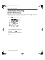
Automatic Printing [Auto-Process]..................................................................................... 46
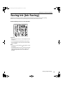
Saving Ink [Ink Saving] ...................................................................................................... 47
Setting up for Printing
48
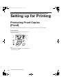
Producing Proof Copies [Proof] ......................................................................................... 48
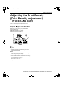
Adjusting the Print Density [Print Density Adjustment] (For EZ3XX only) ......................... 49
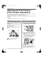
Adjusting the Print Position [Print Position Adjustment] .................................................... 50
Adjusting the Vertical Position ............................................................................................50
Adjusting the Horizontal Position ........................................................................................50
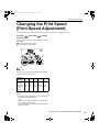
Changing the Print Speed [Print Speed Adjustment]......................................................... 51
Advanced Features
52
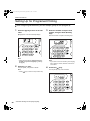
Automatic Sorting into Groups [Program].......................................................................... 52
Setting Up for Programed Printing......................................................................................54
Saving Programs ................................................................................................................59
Retrieving a Program..........................................................................................................60
Making changes to Stored Programs .................................................................................61
Clearing Programs..............................................................................................................62
Idling Action [Idling] ........................................................................................................... 64
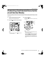
Protecting Confidential Documents [Confidential Mode] ................................................... 65
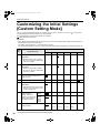
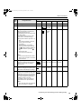
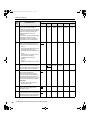
Customizing the Initial Settings [Custom Setting Mode].................................................... 66
Operation Procedure ..........................................................................................................73
IP Address Setting ..............................................................................................................75
Setting Up User Management ........................................................................................... 77
Registering Administrator/Users [Create User] ..................................................................78
Setting Up the Management ON/OFF ................................................................................80
Suspend a user ..................................................................................................................81
Setting the Upper Limit of the User’s Usage ......................................................................82
Clearing the TC or MC for each user..................................................................................83
Reset all User Counters .....................................................................................................84
Setting the ID Counter Report Reminder............................................................................85
Output the ID Counter Report.............................................................................................86
Clearing all User Management Function Settings ..............................................................87
3
REG-LL_EN.book Page 4 Wednesday, September 14, 2011 12:03 PM
Contents
Replacing and Disposing Consumables
88
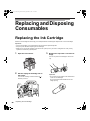
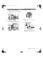
Replacing the Ink Cartridge ............................................................................................... 88
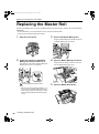
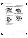
Replacing the Master Roll ................................................................................................. 90
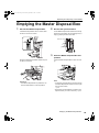
Emptying the Master Disposal Box.................................................................................... 93
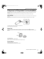
Disposal of Depleted Consumables .................................................................................. 95
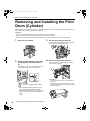
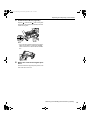
Removing and Installing the Print Drum (Cylinder) ........................................................... 96
Cleaning
98
Safety Guide - Cleaning .................................................................................................... 98
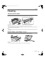
Cleaning ............................................................................................................................ 99
Thermal Print Head ............................................................................................................99
Glass Platen and Platen Cover ..........................................................................................99
Scanner Glass and White Roller of the ADF unit (Option) ...............................................100
Pressure Roller .................................................................................................................100
Printer Exterior..................................................................................................................101
Troubleshooting
102
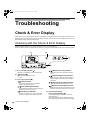
Check & Error Display ..................................................................................................... 102
Checking with the Check & Error Display .........................................................................102
Troubleshooting Tips ....................................................................................................... 112
Appendixes
122
Optional Accessories....................................................................................................... 122
Specifications .................................................................................................................. 123
Feature List...................................................................................................................... 130
Index................................................................................................................................ 134
4
REG-LL_EN.book Page 5 Wednesday, September 14, 2011 12:03 PM
Welcome to the RISO EZ Series Model
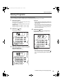
Thank you for purchasing this printing machine that produces clear prints with easy key operations. Besides many
useful functions as a printer, the machine provides you with various conveniences such as Progressive Arrow indicators that show the progress of the master-making and printing processes and the Receiving Tray Paper Guide that
allow you to easily pick up printed copies.
About This User's Guide
This machine comes with the following three user’s guides.
z RISO EZ Series User’s Guide (this manual)
This user’s guide explains the machine’s operations via various functions and handy tips. It also contains user
cautions, information on storing and changing consumables, and troubleshooting procedures.
z RISO Printer Driver User’s Guide (included as a PDF file in the attached CD-ROM)
This user’s guide explains the procedures for printing from a computer.
z RISO Utility Software User’s Guide (included as a PDF file in the attached CD-ROM)
This user’s guide explains how to use the software of the “RISO COPY COUNT VIEWER” and “RISO USB PRINT MANAGER”.
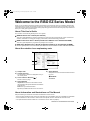
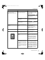
About the notation in an explanatory note
1
4
2
5
3
1) Chapter Title
2) Control panel key
5) Safety Remark
The pictogram in a sentence designates a key on
the control panels.
3) Cross-reference Remark (
)
Shows a reference page.
Safety instructions are described under the following icons.
AWARNING:
BCaution:
4) Advice Remark
Important!:Provides such information as those
that should be paid special attention and inhibited
performances.
Note:Gives you useful information.
Tip:Gives you additional hints for more convenience.
About Information and Illustrations on This Manual
Keep the following in mind about information and illustrations in this manual.
• Some functions described in this manual are supported only by the EZ3XX; those are unavailable on the EZ2XX.
• For the illustrations of the machine’s outlines and control panels, those for the EZ371A have been used.
• The optional Auto Document Feeder AF-VI is referred to as the “ADF unit (Option)”.
Welcome to the RISO EZ Series Model
5
REG-LL_EN.book Page 6 Wednesday, September 14, 2011 12:03 PM
Getting Acquainted
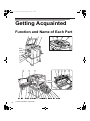
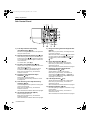
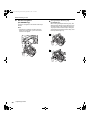
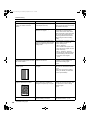
Function and Name of Each Part
6
Function and Name of Each Part
REG-LL_EN.book Page 7 Wednesday, September 14, 2011 12:03 PM
Getting Acquainted
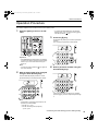
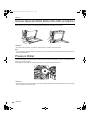
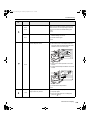
1) Platen Cover
Opened and closed when placing the original.
2) Sub Control Panel ()p.10)
3) Glass Platen ()p.99)
Place an original face down.
4) Main Control Panel ()p.8)
5) Master Disposal Box ()p.93)
Holds discarded masters.
6) Paper Feed Pressure Adjustment Lever
()p.20)
Adjusts the paper feed pressure according to
paper in use.
7) Feed Tray Ascent/Descent Button ()p.21)
Lowers or raises the Paper Feed Tray when
changing or adding paper.
8) Paper Feed Tray ()p.20)
9) Feed Tray Paper Guides ()p.20)
Hold and guide paper.
Slide to fit to the sides of paper.
10) Feed Tray Paper Guides Lock Lever
()p.20)
Lock the Feed Tray Paper Guides.
11) Horizontal Print Position Adjustment Dial
()p.50)
Move the print position to the left or right.
12) Auto Document Feeder (Option)
The Feeder can hold approximately 50 sheets of
the original sheets (80 g/m2 (21-lb bond)). Place
the original face-down.
13) ADF Original Receiving Tray
Scanned originals are ejected into this tray.
14) ADF Original Release Lever ()p.106)
If an original is jammed, pull this lever to the right to
eject from the ADF unit.
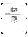
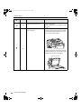
27) Counter
Counts the number of copies (total print counter)
and the number of made masters (master
counter).
28) Print Drum (Cylinder) Release Button
()p.96)
Unlocks the Print Drum (Cylinder) for removal.
29) Master Making Unit Handle ()p.90)
30) Master Making Unit Release Button
()p.90)
Unlocks the Master Making Unit for removal.
31) Stabilizer
32) Power Switch
33) Paper Jump Wing
Automatically adjusts to keep printed paper neatly
stacked.
34) Paper Jumping Wing Adjustment Dial
(For EZ3XX only) ()p.22)
Adjusts according to the finish and size of paper in
order to align printed paper.
35) Paper Arranger (For EZ3XX only) ()p.22)
Press to open for aligning printed paper.
36) Receiving Tray Paper Guides ()p.22)
Align printed paper neatly.
Slide according to the width of paper to be printed.
37) Paper Stopper ()p.22)
Stops paper printed and ejected into the Paper
Receiving Tray.
Slide according to the length of paper to be printed.
38) Paper Receiving Tray ()p.22)
39) AC inlet
Do not touch the POWER switch on the upper part
of the AC inlet (power cord connection). Changing
the POWER switch setting by mistake will cause
damage.
15) ADF Original Guides
Slide and adjusts to the width of the original to hold
together.
16) Front Cover
17) Ink Cartridge Cap Holder ()p.88)
18) Master Making Unit ()p.90)
19) Master Making Unit Cover ()p.90)
20) Thermal Print Head
21) Master Guide Flap ()p.90)
22) Master Roll ()p.90)
23) Master Roll Holder ()p.90)
24) Ink Cartridge ()p.88)
25) Print Drum (Cylinder) Handle ()p.96)
26) Print Drum (Cylinder) ()p.96)
Function and Name of Each Part
7
REG-LL_EN.book Page 8 Wednesday, September 14, 2011 12:03 PM
Getting Acquainted
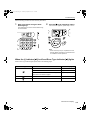
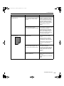
Control Panels
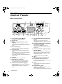
Main Control Panel
1
9
2
10
11
3
12
13
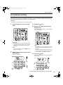
1) Check & Error Display ()p.102)
4
14 15 16 17
5) Progress Arrows
Indicates master-making and printing progress
status.
When making masters is ready, all the indicators
above the Master-Making Key light.
When printing is ready, all the indicators above the
Print Key light.
6) Print Key
Makes the printer be ready for printing.
7) Wake-Up Key / Logout Key
Wakes up the printer in Energy Saving mode.
Use this key also to log out from the machine.
8) Auto-Process Key/Indicator ()p.46)
Performs non-stop operation from master-making
through printing.
When activated, the indicator besides the key
lights.
8
Control Panels
19 20
21
Selects the print speed from five levels.
The indicator above the keys shows the current
speed level.
10) Print Density Adjustment Keys/Indicator
(For EZ3XX only) ()p.49)
Selects the print density from five levels.
The indicator above the keys shows the current
density level.
4) Master-Making Key
Makes the printer be ready for making masters.
7 8
()p.51)
2)
indicator
3) Print Quantity Display (Error number
Shows the number of printed copies, numeric values entered for various settings, and error numbers.
18
6
9) Print Speed Adjustment Keys/Indicator
Indicates error locations and status.
display)
5
11) Vertical Print Position Adjustment Keys/
Indicator ()p.50)
Adjusts the print position in the vertical direction
(within ±15 mm (±1/2")) after making a master.
The indicator above the keys shows the offset
amount from the center.
To clear the offset amount, press
.
12)
Key
Use when setting up for programed printing.
13) Print Quantity Keys (0 to 9 Keys)
Use to enter the number of copies to be printed or
to enter other numeric values.
14) C Key
Cancels entered numeric values or resets the
counter to zero.
15) P Key/Indicator ()p.52)
Allows the printer to print and group copies as
specified (programed printing).
When activated, the indicator above the key lights.
REG-LL_EN.book Page 9 Wednesday, September 14, 2011 12:03 PM
Getting Acquainted
16) + Key
Use when setting up for programed printing or
when changing the initial settings.
17) × Key
Use when setting up for programed printing.
18) Start Key
Starts master-making or printing process or executes specified operations.
The key is lighted only when the key is active.
19) Proof Key ()p.48)
Use to check print result after adjusting the print
position, for example.
This allows you to print proof copies without affecting the value on the Print Quantity Display.
20) Reset Key
Returns all settings to the initial settings.
21) Stop key
Stops operation in progress.
Control Panels
9
REG-LL_EN.book Page 10 Wednesday, September 14, 2011 12:03 PM
Getting Acquainted
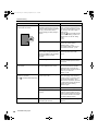
Sub Control Panel
1) Free Reproduction Size Display
()p.34)
Shows the enlargement/reduction ratio specified
using the zoom function.
Each time you press the key, the Image Processing mode is changed.
When the Line mode is selected,
lights. When
the photo mode is selected,
lights. When the
Duo(text/photo) mode is selected, both
and
light.
2) Reproduction Size Selection Key ()p.37)
When selecting from among the standard reproduction sizes, press
/
to switch the selection.
The corresponding indicator lights to indicate the
current selection.
To restore 100%, press
.
3) Zoom Key (For EZ3XX only) ()p.38)
Allows you to change the reproduction size in the
range from 50% to 200%.
After pressing , you can change the size in
increments of 1% using the selection keys.
Each time you press the key, the function is
switched on and off.
4) Scanning Level Adjustment Keys/
Indicator ()p.39)
Select from five scanning levels.
The indicator above the keys shows the current
scanning level.
5) Auto Scanning Level Adjustment Key/
Indicator ()p.39)
Automatically selects the optimum scanning level
for the current original.
Each time you press the key, the function is
switched on and off.
When activated, the indicator above the key lights.
6) Ink Saving Key/Indicator ()p.47)
Makes the printer save ink.
Each time you press the key, the function is
switched on and off.
When activated, the indicator above the key lights.
10
7) Image Processing Selection Key/Indicator
(For EZ3XX only) ()p.38)
Control Panels
8) Pencil Key/Indicator ()p.35)
Select for an original written using a pencil.
Each time you press the key, the function is
switched on and off.
When activated, the indicator above the key lights.
9) Dot Screen Selection Key/Indicator
(For EZ3XX only) ()p.36)
Adjusts shade in pictures when printing.
Each time you press the key, the selection is
switched among
(COARSE) →
(FINE) →
and no shade. The corresponding indicator lights
depending on the selection.
10) 2-UP Key/Indicator ()p.41)
Allows side-by-side printing with a single paper.
Each time you press the key, the function is
switched on and off.
When activated, the indicator above the key lights.
11) Book Key/Indicator ()p.40)
Use when placing a magazine or book as an original for printing.
Each time you press the key, the function is
switched on and off.
When activated, the indicator above the key lights.
REG-LL_EN.book Page 11 Wednesday, September 14, 2011 12:03 PM
Getting Acquainted
12) Interface Key/Indicator ()p.32)
When connected with a computer (optional kit
needed), switches between line connection and
disconnection.
When the line is in connection, the indicator above
the key lights.
13) Custom Key/Indicator ()p.66)
Use when changing the initial settings.
When activated, the indicator above the key lights.
14) Idling Key/Indicator ()p.64)
Sets up for idling.
Each time you press the key, the function is
switched on and off.
When activated, the indicator above the key lights.
15) Confidential Key/Indicator ()p.65)
Prevents confidential documents from being copied.
Each time you press the key, the function is
switched on and off.
When activated, the indicator above the key lights.
Control Panels
11
REG-LL_EN.book Page 12 Wednesday, September 14, 2011 12:03 PM
Before Starting to Use
Safety Guide - Installation
This section describes the precautions to be observed when installing the machine. Read this section before installing the machine.
Note:
• Your dealer (or authorized service representative) will help you to determine a proper location for the machine at
the time of delivery.
Installation
AWARNING:
• Place the machine on the dedicated stand for this model or on a flat and stable surface (maximum of 10 mm (3/8
inches) differential allowed). Injury might occur if the machine falls.
• Install the machine in a well-ventilated area. Failure to do so may result in serious health problems.
BCaution:
• Install the machine near the electrical outlet to avoid using an extension cord between the machine and the electrical outlet. If an extension cord is absolutely required, do not use one longer than 5 m (15 feet).
• Allow at least 10 cm (4 inches) or more of clearance behind the machine so that you can unplug the machine in
case of technical difficulties.
• Keep the machine away from dusty environments. Failure to do so may result in fire.
Important!:
• Avoid installing the machine in the locations listed below. Failure to observe this precaution may lead to machine
failure.
– Locations with exposure to direct sunlight, such as locations close to windows (Curtain all windows that might
expose the machine to direct sunlight)
– Locations that are subject to sudden changes in temperature
– Extremely hot and humid locations or cold and dry locations
– Heated locations
– Locations exposed to direct cold air, direct hot air, or direct radiant heat
– Locations of poor permeability and ventilation
12
Safety Guide - Installation
REG-LL_EN.book Page 13 Wednesday, September 14, 2011 12:03 PM
Before Starting to Use
Power connection
AWARNING:
• Do not overload the electrical outlet or extension cord, nor damage the power cord by placing heavy objects on it
or pulling or bending it. This can result in fire or electric shock.
• Do not pull the power cord but hold the plug itself when unplugging it. This can damage the cord and result in fire
or electric shock.
• Do not plug or unplug the power cord if your hands are wet. This can result in electric shock.
BCaution:
• Pull out the power cord plug from the electrical outlet more than once a year and clean the prongs of the plug and
their surroundings. Dust collected on these areas can result in fire.
Important!:
• Check the power cord and plug for poor connections. Plug the power cord securely into a nearby electrical outlet.
• Be sure to turn off the POWER switch when connecting or disconnecting a cable.
• Do not touch the POWER switch on the upper part of the AC inlet (power cord connection). Changing the POWER
switch setting by mistake will cause damage.
Safety Guide - Installation
13
REG-LL_EN.book Page 14 Wednesday, September 14, 2011 12:03 PM
Before Starting to Use
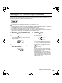
Connection with a Computer (Option)
With an optional interface board (RISO PC Interface Card USB2.0) installed, you can directly send data from a connected computer to the machine as an original for printing. Because digital data itself is used for making a master, the
finish of prints becomes outstanding.
Connection Method
z One-to-one connection with a Windows PC
• Cable:
USB cable
Less than 3m (10 feet) Hi-Speed USB
Important!:
• Before making the USB connections, turn
on both the machine and computer, and
wait until the initial screen is displayed.
• The maximum allowable voltage for
USB connector input and output is 5 V.
• For the USB connections, use a
commercially available USB cable (that
conforms to the USB 2.0 standard).
Note:
• The RISO PC Interface Card USB2.0
(option) is required.
z Network connections
• Cable:
Ethernet cable
Shielded cable that supports 10BASE-T
or 100BASE-TX
Important!:
• Before making the Ethernet connections,
turn off both the machine and computer.
Note:
• The RISO PC Interface Card USB2.0
and the RISO Network Card (both
options) are required.
• If the optional network interface card
“RISO Network Card” is installed, the
machine can be connected with a
Macintosh computer. For details, see
the User’s Guide of RISO Network Card.
14
Connection with a Computer (Option)
USB port on the machine
USB
port
USB port on
your computer
REG-LL_EN.book Page 15 Wednesday, September 14, 2011 12:03 PM
Before Starting to Use
Software Installation
Before printing from a computer connected to the machine via a USB cable, the RISO printer driver must be installed.
Before printing from a computer connected to the machine via a network, both the RISO printer driver and RISO Network Card must be installed. Refer to the Printer Driver User’s Guide and RISO Network Card User’s Guide for
instructions on installation.
Note:
• RISO Network Card is an option.
The software supplied with this machine is as follows:
z RISO Printer Driver
RISO Printer Drivers are for use with RISO Printers only.
Before setup, be sure to read the User’s Guide carefully.
The User’s Guide can be found as a PDF file* in the CD-ROM which came with the RISO Printer.
*To be able to view PDF format files, it is necessary for either Adobe® Reader® or Adobe® Acrobat® Reader®
to be installed.
Adobe® Reader® or Adobe® Acrobat® Reader® software can be freely downloaded from the Adobe website
(http://www.adobe.com/).
z RISO Utility Software
The software package includes the “RISO USB PRINT MANAGER” and “RISO COPY COUNT VIEWER”.
• “RISO USB PRINT MANAGER”
Application that manages the original data stored in the USB Flash Drive on the computer.
• “RISO COPY COUNT VIEWER”
Application that manages the counter data (number of prints, masters, etc.) output to the USB Flash Drive on
the computer.
Connection with a Computer (Option)
15
REG-LL_EN.book Page 16 Wednesday, September 14, 2011 12:03 PM
Before Starting to Use
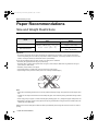
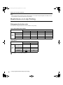
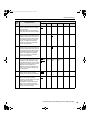
Paper Recommendations
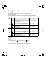
Size and Weight Restrictions
The table shows the specifications of the usable print paper.
Model
EZ391/EZ371/EZ331/EZ301
EZ231/EZ221/EZ201
Usable Printing Paper
Size
100 mm × 148 mm (315/16" × 527/32") to
310 mm × 432 mm (123/16" × 17")
Weight
46g/m2 (12-lb bond) to
210g/m2 (110-lb index)
46g/m2 (12-lb bond) to
157g/m2 (87-lb index)
Important!:
• Even when using paper whose sizes and weight are supported by the machine, it may not pass through the
machine depending on such factors as paper finish, ambient conditions, and storage conditions. For more information, consult your dealer (or authorized service representative).
Do not use the following types of paper, as they can cause jams or misfeeds:
• Extremely thin paper (less than 46 g/m2 (12-lb bond))
• Extremely thick or heavy paper (greater than 210 g/m2 (110-lb index) for EZ3 series or greater than 157 g/m2
(87-lb index) for EZ2 series)
• Wrinkled, curled, folded, or torn paper
• Chemically treated or coated paper (such as thermal or carbon paper)
• Paper having a sticky section or holes (such as an envelope and label paper)
Note:
• Paper with a horizontal grain direction can cause problems with paper supply. Use paper with a vertical grain direction.
• Images are not output onto the entire area of usable print paper. The maximum printing areas differ among models.
)p.19
• When using poorly cut paper or coarse surfaced paper (drawing paper, etc.), arrange the paper neatly before use.
• Depending on the type of paper used, paper dust may be generated when using the machine. Please clean and
ventilate the area adequately.
RISO does not assure that paper outside the above specifications pass through the machine and can be used for
printing.
16
Paper Recommendations
REG-LL_EN.book Page 17 Wednesday, September 14, 2011 12:03 PM
Before Starting to Use
Tips for Better Paper Feeding
To prevent paper jams and misfeeds, follow the directions below:
• When using standard or light-weight paper, set the Paper Feed Pressure Adjustment Lever to “NORMAL” (
).
Then set the Paper Jumping Wing Adjustment Dial (For EZ3XX only) according to the paper size and open all four
Paper Arrangers (For EZ3XX only). For EZ2XX, set the corrugators. )p.20
• When using thick paper (such as card stock), set the Paper Feed Pressure Adjustment Lever and the Paper Jumping Wing Adjustment Dial to “CARD” (
), and open the two inner Paper Arrangers. )p.20
• When using slippery paper, set the Paper Feed Pressure Adjustment Lever to “CARD” (
). )p.20
• Slide the Feed Tray Paper Guides, Receiving Tray Paper Guides, and Paper Stopper to fit the paper size. )p.20
• Use flat printing paper that is free of folds. If curled paper is unavoidable, place the printing paper so that the inner
curled part faces down.
• Paper may stick to the Print Drum (Cylinder) surface if the top margin is too narrow on the original or if the upper
portion of the original uses a large amount of ink. To solve this problem, lower the print position to provide a wider
top margin or reverse the top and bottom of the original. Then restart printing from the beginning.
Storing Environment
Store printing paper in a level, dry area. Storing the paper in an excessively humid area can result in paper jams or
poor print quality.
After unpacking printing paper, keep the remaining paper wrapped and store it in a moisture-proof box. It is highly recommended to put silica gel in the paper storage box.
Paper Recommendations
17
REG-LL_EN.book Page 18 Wednesday, September 14, 2011 12:03 PM
Before Starting to Use
Originals
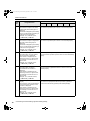
Size and Weight Restrictions
Usable originals are as follows.
Using the Glass Platen
Size
50 mm × 90 mm(131/32" × 39/16") to
310 mm × 432 mm(123/16" × 17")
Using the Optional ADF unit
Weight
Max.10kg
(22lb)
Size
Weight
100 mm × 148 mm(315/16" × 527/32") to
310 mm × 432 mm(123/16" × 17")
50g/m2
(13-lb bond)
to
128g/m2
(34-lb bond)
• Originals are scanned according to the size of paper placed on the Paper Feed Tray when masters are made; for
the same width, the positions of the Feed Tray Paper Guides.
When the placed paper is smaller than an original, not the entire original will be scanned.
When the placed paper is larger than an original, dirt on the glass or shade of the original, for example, may result
in unexpected dirt in the area beyond the size of the original.
• Bound originals can also be used on the Glass Platen.
• You can feed automatically up to 50 originals when using the ADF unit (Option). (When originals of 80 g/m2 (21lb bond) or less are used).
Note:
• Use the Glass Platen when printing the following originals:
–
–
–
–
–
–
–
–
–
Patched or worn originals
Wrinkled, curled, folded, or torn originals
Transparent originals (such as tracing paper or OHP transparencies)
Chemically treated originals (such as thermal or carbon paper)
Originals with correction fluid or glue
Extremely thin originals (less than 50 g/m2(13-lb bond))
Extremely thick originals (greater than 128 g/m2(34-lb bond))
Heavy drawing paper
Originals with staples or clips
• If an original is wrinkled, curled, or creased flatten it thoroughly so that the originals can be pressed directly onto
the Glass Platen during processing.
• If correction fluid or glue is used on an original, thoroughly dry it before placement.
• For an original patched with thick paper, the shade of the patched paper may also be printed.
18
Originals
REG-LL_EN.book Page 19 Wednesday, September 14, 2011 12:03 PM
Before Starting to Use
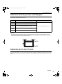
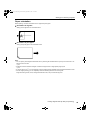
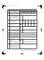
Maximum Printing Areas and Margins
The maximum printing areas are as follows.
Model
Maximum Printing Area
EZ391
291 mm × 425 mm (117/16" × 163/4")
EZ371
291 mm × 413 mm (117/16" × 161/4")
EZ331
EZ231
251 mm × 357 mm (97/8" × 141/16")
EZ301
EZ201
210 mm × 290 mm (81/4" × 117/16")
EZ221
210 mm × 357 mm (81/4" × 141/16")
Usable Maximum Print Paper Size
310 mm × 432 mm (123/16" × 17")
Important!:
• No matter which size of originals is printed, the margins indicated on the figure are required for the originals.
Reduce the original if necessary to fit it inside of the margins. Place an original so that its end having a 5 mm(3/16")
margin at least comes to the left of the Glass Platen.
Materials Not to Be Printed
Do not use the machine in any manner which violates the law or infringes on established copyrights, even when making copies for personal use. Consult your local authorities for further details. In general, use discretion and common
sense.
Originals
19
REG-LL_EN.book Page 20 Wednesday, September 14, 2011 12:03 PM
Before Starting to Use
Preparing to Print
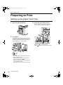
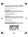
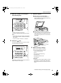
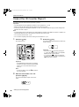
Setting up the Paper Feed Tray
1
Open the Paper Feed Tray.
3
Select the paper feed pressure.
Position the Paper Feed Pressure Adjustment
Lever according to the finish of the paper.
2
Load paper.
Place paper in the printing orientation, and slide
the Feed Tray Paper Guides to fit to the sides of
the paper. Then turn the right and left Feed Tray
Paper Guide Levers to lock the guides.
NORMAL (
):For standard paper
CARD (
):For thick or smooth-surface paper
:Unlock
:Lock
Important!:
• Do not use paper of inappropriate sizes or mix
paper of different sizes.
• Before sliding the Feed Tray Paper Guides,
position its lock lever to
.
• Make sure that the Feed Tray Paper Guides fit
tight up against the paper.
Failure to do so can produce undesired results.
20
Preparing to Print
REG-LL_EN.book Page 21 Wednesday, September 14, 2011 12:03 PM
Before Starting to Use
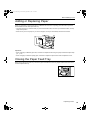
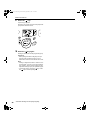
Adding or Replacing Paper
When you add paper or replace with paper of a different size at the time of printing, press the Feed Tray Ascent/
Descent Button to lower the Paper Feed Tray.
• The Paper Feed Tray is lowered while you press and hold the button, and when you release the button, the tray
stops at that position.
• When the tray runs out of paper or you remove all paper, the tray is automatically lowered to the bottom.
Important!:
• When changing to a different paper size, remember to readjust the Receiving Tray Paper Guides and Paper Stopper. )p.22
• When changing to a different quality paper, remember to adjust the Paper Feed Pressure Adjustment Lever.
Closing the Paper Feed Tray
Before closing the Paper Feed Tray, remove the paper and widen the Feed Tray Paper Guides to the limits. Then
close the Paper Feed Tray.
Preparing to Print
21
REG-LL_EN.book Page 22 Wednesday, September 14, 2011 12:03 PM
Before Starting to Use
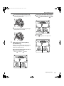
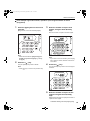
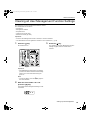
Setting up the Paper Receiving Tray
1
Open the Paper Receiving Tray.
3
Set the Paper Stopper.
1) Raise the Paper Stopper.
2) Slide to fit the length of the paper.
Pull the Paper Receiving Tray down until it comes
to a rest.
2
The subsequent steps differ depending on the
models.
Position the Receiving Tray Paper
Guides.
1) Raise the Receiving Tray Paper Guides.
2) Hold their lower part and slide them to fit the
paper width.
• For EZ3XX, go to step 4.
• For EZ2XX, go to step 6.
4
Adjust the Paper Arrangers.
(For EZ3XX only)
Alignment of paper is affected by sizes and
strength of paper. Adjust the Paper Arrangers so
that printed paper is aligned.
z For plain paper
Press to open all of the four Paper Arrangers.
Important!:
• For thick paper such as drawing paper, position
the Receiving Tray Paper Guides a little wider
than the actual paper width.
• When you move the Paper Feed Tray using the
Horizontal Print Position Adjustment Dial, reposition also the Receiving Tray Paper Guides. If
the guides are not correctly positioned, a problem such as a paper jam can occur.
22
Preparing to Print
REG-LL_EN.book Page 23 Wednesday, September 14, 2011 12:03 PM
Before Starting to Use
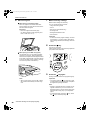
z For plain paper with images lopsided on page
Press to open the two Paper Arrangers on the
more heavily printed side.
z For plain paper widths that are either equal to or
smaller than Letter or that are smaller than B4
Set to
Legal Letter Statement or
A4 B5.
z For thick paper
Press to open the two Paper Arrangers (right
and left) closer to the machine.
z For thick paper
Set to
5
regardless of the paper size.
Adjust the Paper Jumping Wing.
(For EZ3XX only)
Adjust the Paper Jumping Wing Adjustment Dial
according to the type and width of the paper
loaded in the Paper Feed Tray.
z For plain paper widths larger than Letter, or
equal to or larger than B4
Set to
Ledger or
A3 B4.
Preparing to Print
23
REG-LL_EN.book Page 24 Wednesday, September 14, 2011 12:03 PM
Before Starting to Use
6
Set the corrugators.
(For EZ2XX only)
Lower the corrugators to the inside of the Paper
Guides.
Note:
• Usually the corrugators should be lowered.
When using thick paper, you do not need to
lower the corrugators.
24
Preparing to Print
z Closing the Paper Receiving Tray
(For EZ3XX only)
When closing the Paper Receiving Tray, first
slide the Paper Stopper to the edge of the tray
and fold it inward. Then widen the Receiving
Tray Paper Guides with the Paper Arrangers
closed and fold the guides inward. Lastly close
the Paper Receiving Tray.
REG-LL_EN.book Page 25 Wednesday, September 14, 2011 12:03 PM
Before Starting to Use
z Closing the Paper Receiving Tray
(For EZ2XX only)
When closing the Paper Receiving Tray, first
slide the Paper Stopper to the edge of the tray
and fold it inward. Then raise the corrugators,
widen the Receiving Tray Paper Guides, and
fold the guides inward. Lastly close the Paper
Receiving Tray.
Preparing to Print
25
REG-LL_EN.book Page 26 Wednesday, September 14, 2011 12:03 PM
Basic Operations
Safety Guide - Handling and Operation
This section describes the precautions to be observed when handling the machine. Read this section before operating the machine.
Operation Environment
Important!:
• Operate the machine under the following appropriate environment conditions.
Temperature range: 15°C to 30°C(59°F to 86°F)
Humidity range: 40% to 70% (noncondensing)
Machine Handling
AWARNING:
• Do not place water containers or metallic objects on the machine. Fire or electric shock may occur if water or metallic objects fall into the machine.
• Do not use combustible spray and flammable solvent near the machine.
If sprayed gas and flammable solvent contact electronic components inside the machine, fire or electric shock
might occur.
• Do not insert any metallic material or flammable substance into the machine through any opening. This can result
in fire or electric shock.
• Do not remove machine covers. Exposing internal parts may result in electric shock.
• Do not disassemble or rebuild the machine by yourself. This can result in fire or electric shock.
• If the machine emits excessive heat, smoke or foul odor, immediately turn off the POWER, unplug the power cord
and contact your dealer (or authorized service representative). Failure to do so can result in fire or electric shock.
• If something drops inside the machine, immediately turn off the POWER, unplug the power cord and contact your
dealer (or authorized service representative). Failure to do so can result in fire or electric shock.
• Never stick your hands or fingers in the openings of the machine during operation.
• Keep loose clothing or long hair away from moving parts to avoid becoming entangled.
• Do not place heavy objects on the machine. The objects might fall and cause injury.
• Contact your dealer (or authorized service representative) before moving the machine.
BCaution:
• Never insert fingers, etc. into the openings around Paper Feed Tray and Paper Receiving Tray. This can result in
injury.
• Because ink may have stuck to areas around the Print Drum (Cylinder) or inside the machine when the Print Drum
(Cylinder) was removed, be careful not to contact them with your hands or clothes.
When ink has stuck to your hands, etc., wash it off with detergent as soon as possible.
• When you remove paper by inserting a hand inside the machine, be careful not to touch the paper separation hook.
Because the tip of paper separation hook is sharp, it might cause injury.
• Do not open any covers or move the machine during operation.
• Unplug the power cord, if you do not use the machine for a long time.
26
Safety Guide - Handling and Operation
REG-LL_EN.book Page 27 Wednesday, September 14, 2011 12:03 PM
Basic Operations
• The machine has precision parts and driving parts inside. Do not handle the machine in other ways than described
in this guide.
• Do not apply any shock to the machine.
• Do not stand the Print Drum (Cylinder) vertically. Doing so may pollute the floor, etc.
Important!:
• Do not unplug the power cord or turn off the power during operation.
• Be sure to open and close all machine covers gently.
Consumables
Important!:
• For ink and master Roll, it is recommended to use the products specified by RISO.
• Store consumables such as master Roll and ink properly.
Do not store consumables in the following places:
– Locations that are subject to direct sunlight or bright locations that are close to windows
(If there is no other choice, curtain the window.)
– Locations that are subject to rapid changes in temperature
– Extremely hot and humid locations or extremely cold and dry locations
Ink Handling
BCaution:
• If ink gets into your eyes, flush it out immediately with plenty of water. If irritation continues, seek medical attention.
• If ink comes into contact with your skin, wash it off thoroughly using soap.
• If someone swallows ink by mistake, force large quantities of water (or milk) without inducing vomiting, and watch
his/her condition.
• Allow plenty of ventilation during printing.
• If you feel unwell during use, seek medical advice.
• Only use the ink for printing purposes.
• Keep the ink out of the reach of children.
Location of
Caution Label
This machine has a
caution label meant to ensure safe operation.
Follow the indication of the label and use the machine safely.
Safety Guide - Handling and Operation
27
REG-LL_EN.book Page 28 Wednesday, September 14, 2011 12:03 PM
Basic Operations
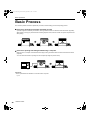
Basic Process
The machine presents two basic operational processes; master-making process and printing process.
z Process for printing from a paper document or book
A placed original is scanned by the scanner, and a generated master is rolled around the Print Drum (Cylinder).
After a while, proof copy is performed. After checking the print result, enter the number of copies to be printed and
start printing.
z Process for printing with data generated using a computer
Data sent from a computer is transformed into images, and a generated master is rolled around the Print Drum
(Cylinder).
You can send instructions for printing from the computer (through the printer driver).
Important!:
• Some optional kits are needed for connection with a computer.
)p.14
28
Basic Process
REG-LL_EN.book Page 29 Wednesday, September 14, 2011 12:03 PM
Basic Operations
Basic Operations
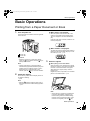
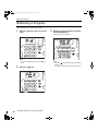
Printing from a Paper Document or Book
1
z When “ECO” is displayed:
Turn the power on.
When the power switch is set to ON or the
machine is activated from the Sleep status,
“ECO” is displayed in the Print Quantity Display.
If the PIN code-input is needed, “PASS” is continuously displayed.
The power switch is located on the lower right side
of the machine.
z When “PASS” is displayed:
The PIN code-input is required when “PASS” is
flashing on the Print Quantity Display. For the
PIN code-input, see )p.31.
: Power On
: Power Off
Important!:
• When the machine is in the Energy Saving
mode, the
key is lighted. Press the
key to
wake up the machine.
Note:
• If data is received from a computer while the
machine is being operated, that data may be given
a higher priority for making a master. To give a
higher priority to an original placed on the
machine, press the
key to turn off its indicator.
2
Check the display.
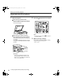
3
Place an original.
z When placing on the Glass Platen
Open the Platen Cover and place the original
face down. Align the center of the original with
the mark on the left-hand side of the glass.
After placing the original, slowly close the
Platen Cover.
Magazines, books, scrap books, etc. should be
placed on the Glass Platen. )p.19
Check that any Check & Error Display section is
not lighted or blinking.
)p.102
Note:
• When the
indicator is lighted, idling action is
activated just before the master-making operation.
)p.64
Note:
• When placing an original is completed, the
process is automatically changed to the
master-making mode; the Master-Making
indicator on the Control Panel lights. If the
indicator is not lighted, press the
key.
Basic Operations
29
REG-LL_EN.book Page 30 Wednesday, September 14, 2011 12:03 PM
Basic Operations
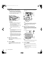
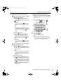
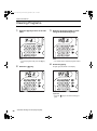
z When placing in the ADF unit (Option)
Check the proof copy result; e.g., print position
and density.
Use the ADF unit if you are printing multiple
originals in succession. Place originals face
down and then adjust the ADF Original Guides
to the width of the originals. Insert the originals
as far into the ADF unit as possible.
Important!:
• The sizes of originals to be placed in the
ADF unit must be 100 mm × 148 mm
(315/16"×527/32") at least. For smaller originals, use the Glass Platen.
• Do not load inappropriate originals or originals of mixed sizes into the ADF.
This can causes paper jams or trouble.
)p.18
Note:
• You can change the settings for print position
and density. After changing the settings, press
, and then check the proof copy result.
)p.48~)p.51
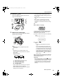
6
The specified number is shown on the Print Quantity Display.
Note:
• You can place up to about 50 sheets of originals in the ADF unit.
• The Custom Setting mode allows you to set
the Auto-Process to perform automatically
when an original is placed in the ADF unit.
)p.66
• If using the Custom Setting mode you select
ON for Semi-Auto, the next master-making is
automatically started and then the machine will
stop when the ADF unit contains originals.
)p.66
4
Make necessary settings.
Make various settings including image processing
mode selection.
)p.34~)p.47
5
Enter the number of copies to be
printed, using the Print Quantity keys.
Press the
Note:
• If you enter an incorrect number, press the [C]
key, and then enter the correct number.
key.
The original is scanned, and a master is made.
After a master has been made, a proof copy is
printed.
7
Press the
key.
The specified number of copies will be printed.
Note:
• You can change the print speed using the Print
Speed Adjustment keys.
)p.51
• If printing is stopped halfway, check the display.
)p.102~)p.111
30
Basic Operations
REG-LL_EN.book Page 31 Wednesday, September 14, 2011 12:03 PM
Basic Operations
8
Press the
key.
After printing has been finished, return the settings to the initial settings.
• The stop bar lights: Indicating Stop timing
• Both 1 and 2 light: Master-making process can
be executed.
• Both 3 and 4 light: Printing process can be executed.
• Both 1 and 4: In the Auto-Process mode
• The machine halts and halfway arrow segments blink: A restoration instruction is being
waited.
Tip:
When “PASS” is displayed
9
Remove the printed paper.
Pull and open the Receiving Tray Paper Guides,
and then remove the paper.
If “PASS” flashes on the Print Quantity Display,
the User Management function is set by the
administrator. Input a PIN code.
1) Enter your PIN code using the Print Quantity
keys.
The PIN code is shown as “-”.
2) Press the
Note:
• For EZ2XX, lift the corrugators and pull the
guides open.
Tip:
• Depending on the operation status of the
machine, different Progressive Arrow sections
light or blink.
Progress Arrows
1)
2)
3)
4)
Master-making progress arrow
Master-making stop bar
Printing progress arrow
Printing stop bar
key.
Note:
• Consult your administrator for the PIN
code.
• If an incorrect PIN code is entered, the
alarm sounds and the PIN code input mode
is restored. Re-enter the correct PIN code.
• If a disabled user set in the Custom Setting
mode performs the procedures above, the
alarm sounds and an Error No. (F-39) is
displayed. Press the
key to release the
error. )p.81
After access has been verified, the Print Quantity
Display displays the Normal mode, and you can
start the printing operation.
Important!:
• After printing operation, press the
key to log
out. (If you do not log out, access privileges will
be inactivated with “Auto clear time”). )p.67
To prevent the use by the unauthorized third
parties, we recommend you log out from the
machine.
• Arrow 1 blinks and increments by one segment:
Master-making process in progress
• Arrow 3 blinks and increments by one segment:
Printing process in progress
Basic Operations
31
REG-LL_EN.book Page 32 Wednesday, September 14, 2011 12:03 PM
Basic Operations
Printing with Data Generated by a Computer
(Optional Kit Required)
1
Set the power switch to
turn the power on.
(ON) to
2
Check that the
indicator is on.
If the indicator is off, press the
key.
The power switch is located on the lower right side
of the machine.
Important!:
• If the
key is pressed while the
indicator
is flashing, the data currently being received or
which is waiting for output is deleted.
: Power On
: Power Off
Important!:
• When the machine is in the Energy Saving
mode, the
key is lighted. Press the
key to
wake up the machine.
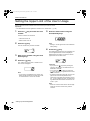
z When “ECO” is displayed:
When the power switch is set to ON or the
machine is activated from the Sleep status,
“ECO” is displayed in the Print Quantity Display.
If the PIN code-input is needed, “PASS” is continuously displayed.
z When “PASS” is displayed:
The PIN code-input is required when “PASS” is
flashing on the Print Quantity Display. For the
PIN code-input, see )p.31.
32
Basic Operations
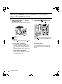
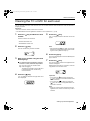
3
Check the paper and Drum (Cylinder) color (colour).
To change the paper or Drum (Cylinder) color
(colour), replace the paper on the Paper Feed
Tray or replace the Color Drum (Cylinder) as
needed.
REG-LL_EN.book Page 33 Wednesday, September 14, 2011 12:03 PM
Basic Operations
4
Send document data from the computer.
While the machine is receiving data, the
indicator blinks.
When data-reception is complete, printing starts
automatically at the printer driver settings.
Important!:
• You cannot make various settings including
image processing mode, by operating the
machine. Only the printer driver allows such
settings. For details, see the user’s guide of the
printer driver.
Note:
• You can also use the printer driver to stop the
master-making or printing process at any point.
For details, see the User's Guide of the printer
driver.
• By checking which Progress Arrow segments
light or blink, you can identify at which status
the machine is stopped. )p.31
When the machine has been halted with
Progress Arrow segments blinking, it is waiting
for a start instruction. Press the
key to
resume the process indicated by the blinking
arrow segments.
• If you press the
key when the machine is not
in use after the master-making process or when
you stop the machine during printing, the page
number currently being printed will be displayed
in Print Quantity Display.
• Data is printed in the order in which it was
received.
Tip:
• About the
indicator
The status of the machine and data reception
can be understood from the lighting of the
indicator.
Lighting of
Indicator
Description
Lit solidly
The machine is ready to
receive data from the
computer.
Flashing
rapidly
The machine is receiving
data.
Flashing
slowly
The machine is waiting to
output data. (The received
data has been digitally
processed and is waiting for
the output command.) Or
the machine is making a
master of or printing the
digitally processed data.
Out
The machine cannot
receive data.
Note:
• While the
indicator is flashing, the data currently being received or which is in waiting for
output can be deleted by pressing the
key.
Tip:
When the computer sends document data, the
machine automatically receives it and starts the
master-making process. It is judged whether or
not the machine is in use, based on how much
time elapsed after any key had been pressed last
or printing had been finished.
This time period is called the “Reservation Period”.
You can change the initial setting for the occupied
time in the Custom Setting mode. )p.66
Basic Operations
33
REG-LL_EN.book Page 34 Wednesday, September 14, 2011 12:03 PM
Setting up for
Scanning Originals
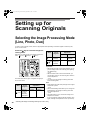
Selecting the Image Processing Mode
[Line, Photo, Duo]
In order to make a quality master, select an appropriate mode depending on whether originals contain only text,
photo or both of them.
Press the key to select the Image Processing mode.
Mode
Each time you press the key, the indicators light in the
order;
(Line)→ (Photo)→
(Duo)
Photo
Type of
Originals
Only photos
contained
Both text
Duo and photos
contained
The table shows which types of originals are appropriate for each mode.
Mode
Line
34
Type of
Originals
Only text
contained;
e.g., text
document,
newspaper
Scanning Level
Adjustment
1-5
Available
AUTO
Available
Scanning Level
Adjustment
1-5
AUTO
Available
Not
Available
Available
Not
Available
Important!:
• With the Photo mode or Duo mode selected, you can
process images with a dot screening when printing.
(For EZ3XX only)
)p.36
• With the Photo mode or Duo mode selected, you
cannot select “Auto” for the scanning level. Perform
manual adjustment.
)p.39
• You cannot use the Image Processing mode and
Pencil mode together.
Note:
• Select the Pencil mode when printing from an original
written with a pencil.
)p.35
• The Custom Setting mode allows you to change the
initial setting for the Image Processing mode and
Duo mode adjustment.
)p.66
• The initial setting is “Line” and the Scanning Level
Adjustment is “AUTO”.
If “Line” is changed to another mode and set back to “Line”
again, Scanning Level Adjustment is set to 3 (not AUTO).
Selecting the Image Processing Mode [Line, Photo, Duo]
REG-LL_EN.book Page 35 Wednesday, September 14, 2011 12:03 PM
Setting up for Scanning Originals
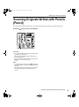
Scanning Originals Written with Pencils
[Pencil]
This function allows clearer printing from such originals containing faint contents as those written with pencils.
Press the
key to turn on its indicator.
Important!:
• You cannot use the Pencil mode and Image Processing mode at the same time.
• You cannot use the Pencil mode and Dot Process
mode at the same time.
• When in the Pencil mode, adjust the scanning level
manually. You cannot select “Auto”.
)p.39
Note:
• To clear the Pencil mode, press the
key again to
turn off its indicator or select another image processing mode.
• The Custom Setting mode allows you to change the
initial setting for the Pencil mode adjustment.
)p.69
Scanning Originals Written with Pencils [Pencil]
35
REG-LL_EN.book Page 36 Wednesday, September 14, 2011 12:03 PM
Setting up for Scanning Originals
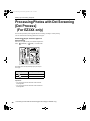
Processing Photos with Dot Screening
[Dot Process]
(For EZ3XX only)
This function processes photo originals with dot screening, resulting in clearer printing.
You can select the dot screening pattern from two types.
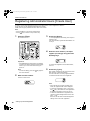
Press the key to select the type of a
dot screening.
Each time you press the key, the indicators light in the
order;
(COARSE)→
(FINE)→ and then OFF.
The table shows the equivalent lpi (line per inch) to
each type:
Type
Equivalent Lpi
COARSE
53
FINE
106
Important!:
• You cannot use the Dot Process mode and Line
mode together.
• You cannot use the Dot Process mode and Pencil
mode together.
36
Processing Photos with Dot Screening [Dot Process] (For EZ3XX only)
REG-LL_EN.book Page 37 Wednesday, September 14, 2011 12:03 PM
Setting up for Scanning Originals
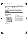
Enlarging and Reducing Originals
[Enlargement/Reduction]
You can enlarge or reduce originals when printing.
Specify the enlargement/reduction ratio by selecting the standard ratios; or specify it in increments of 1%.
Enlarging and Reducing by Standard Ratios
[Standard]
Select the standard ratios when enlarging or reducing standard-sized originals to another standard size or when
increasing margins around the original.
Press the / keys to specify the
enlargement/reduction ratio.
Each time you press the key, the indicator of the
selected ratio lights.
To restore 100%, press the
key.
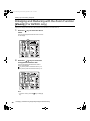
Note:
• To avoid paper jam, flipping or ink smudges on the
back side by design, the machine does not print too
close to the edge. The top edge in particular needs
5 mm (3/16") of margin space.
)p.19
5 mm (3/16") wide area on the top edge (marked ) of
the Glass Platen (or the ADF unit) cannot be
scanned, regardless of enlargement or reduction settings.
• Do not position the original within 5 mm (3/16") of the
top edge, or the top edge of its printed image will be
cut off.
• If the original document has no margin on its top
edge, the top 5 mm (3/16") of its print will be cut off
even when “Margin+” is selected. Move the original
about 5 mm (3/16") inwards from the top edge of the
Glass Platen and reduce the size.
The standard enlargement/reduction ratios differ
among the models.
Check the panel on your machine.
Enlarging and Reducing Originals [Enlargement/Reduction]
37
REG-LL_EN.book Page 38 Wednesday, September 14, 2011 12:03 PM
Setting up for Scanning Originals
Enlarging and Reducing with the Zoom Function
[Zoom] (For EZ3XX only)
Specify the enlargement/reduction ratio between 50% and 200% in increments of 1%.
1
Press the
mode.
key to select the Zoom
The current enlargement/reduction ratio is shown
on the display.
2
Press the
/ keys to select the
enlargement/reduction ratio.
The selected enlargement/reduction ratio is
shown on the display.
key: Each press increases the ratio by 1%.
key: Each press decreases the ratio by 1%.
Note:
• To restore 100%, press the
key.
38
key or the
Enlarging and Reducing Originals [Enlargement/Reduction]
REG-LL_EN.book Page 39 Wednesday, September 14, 2011 12:03 PM
Setting up for Scanning Originals
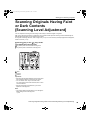
Scanning Originals Having Faint
or Dark Contents
[Scanning Level Adjustment]
You can adjust the scanning level according to the density of text and images on originals.
With “Auto” selected, the density of originals is pre-scanned and the optimum scanning level is automatically set.
Manual adjustment allows you to select from five levels.
For originals containing faint text, select a high level (4 or 5). For such colored (coloured) originals as newspapers,
select a low level (1 or 2).
Press the
key or the / keys under
to adjust the scanning level.
key: Each press decreases the scanning level.
key: Each press increases the scanning level.
:Auto
:Lighter
:Darker
Important!:
• With the scanning level adjusted, print several copies
after remaking masters to check the print result.
• You can select “Auto” only for the Line mode.
You cannot select “Auto” with the Photo, Duo or Pencil mode selected.
• With the Ink Saving mode selected, you cannot
adjust the scanning level.
Note:
• The Custom Setting mode allows you to change the
initial setting for the scanning level.
)p.66
Scanning Originals Having Faint or Dark Contents [Scanning Level Adjustment]
39
REG-LL_EN.book Page 40 Wednesday, September 14, 2011 12:03 PM
Setting up for Scanning Originals
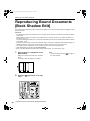
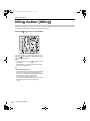
Reproducing Bound Documents
[Book Shadow Edit]
This function erases the binding “spine” shadow when printing from such bound originals with facing pages as magazines and books.
Important!:
• The initial settings have been made for the size of originals whose masters can be made and the width of shadow
to be erased.
(Initial settings: for the size of original, size of paper placed on the Paper Feed Tray; for width of shadow to be
erased, 20 mm(13/16"))
The Custom Setting mode allows you to change the initial settings for the size of originals and the width of shadow
to be erased. )p.66
• If using the Custom Setting mode you have selected “Paper” as the Size of originals for Book shadow editing, use
standard-sized paper. If you place custom-size paper, shadow erasure is not correctly performed.
• The outside of the set original size is not scanned and used for the master-making process.
• “Book Shadow Edit” cannot be used with [2-Up Printing].
• When in the Book Shadow Edit, adjust the scanning level manually. You cannot select “Auto”.
1
Place a book (or a magazine) on the
Glass Platen.
Make sure to place the original in the orientation
below:
The shadow within the dotted box is erased.
2
40
Press the
cator.
key to turn on its indi-
Reproducing Bound Documents [Book Shadow Edit]
Note:
• To clear the setting, press the
turn off its indicator.
key again to
REG-LL_EN.book Page 41 Wednesday, September 14, 2011 12:03 PM
Setting up for Scanning Originals
Printing Originals Side-by-Side
[2-Up Printing]
The same or different originals can be printed side by side.
This is called 2-Up printing.
2-Up printing allows you to place a single original or two different originals
Important!:
• With custom size paper placed, you cannot perform 2-Up printing. Quit 2-Up printing or place standard-sized
paper.
• You cannot use 2-Up Printing and Book Shadow Edit together.
• “2-Up Printing” cannot be used with [Book Shadow Edit].
Single-Original Printing and Two-Original Printing
Single-original printing
This prints from the same original and outputs onto a single sheet of paper side by side.
Two-original printing
This prints from two different originals and outputs onto a single sheet of paper side by side.
The center of printed copies will be free from the shade of originals.
Important!:
• For two-original printing using the Glass Platen, the machine requires a certain period of time before placing the
second original. Use the Custom Setting mode to select 15 seconds or 30 seconds for the interval time; the initial
setting is 15 seconds.
)p.66
Printing Originals Side-by-Side [2-Up Printing]
41
REG-LL_EN.book Page 42 Wednesday, September 14, 2011 12:03 PM
Setting up for Scanning Originals
Note:
• When using the ADF unit (option) for two-original printing, you can place two piled originals in the ADF unit. The
two originals are continuously scanned for 2-Up printing.
Restrictions on 2-Up Printing
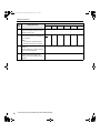
2-Up printing restricts the sizes of paper to be used, paper orientations, and the enlargement/reduction ratios.
Enlargement/reduction ratio
The table shows enlargement/reduction ratios suitable for 2-Up printing.
-EZ371/EZ331/EZ301/EZ231/EZ201Original
A4
B5
A5
B6
A3 (For EZ371 only)
100%
116%
141%
163%
B4
87%
100%
122%
141%
A4
71%
82%
100%
116%
B5
61%
71%
87%
100%
Print
Paper
-EZ391/EZ221Original
Print
Paper
Letter
Statement
Ledger
(For EZ391 only)
100%
155%
Legal
82%
127%
Letter
65%
100%
Statement
50%
77%
:For EZ2XX, you cannot make selections.
42
Printing Originals Side-by-Side [2-Up Printing]
REG-LL_EN.book Page 43 Wednesday, September 14, 2011 12:03 PM
Setting up for Scanning Originals
Paper orientation
Before printing, check the orientations of the original and print paper.
z Orientation of originals
Always place originals in the orientation below.
z Orientation of print paper
Always place print paper in the orientation below.
Note:
• You can specify the enlargement/reduction ratio by selecting the standard ratios or specify it in increments of 1%
using the Zoom function.
)p.37
• Originals must have sufficient margins. Insufficient margins result in inappropriate page layout.
)p.19
• A margin of the 5 mm (3/16") on the left edge of the set original is kept regardless of the enlargement/reduction ratio.
• For two-original printing, you can separately select the following functions for each original.
Image Processing mode, Pencil, enlargement/reduction ratio, dot process/scanning level
Printing Originals Side-by-Side [2-Up Printing]
43
REG-LL_EN.book Page 44 Wednesday, September 14, 2011 12:03 PM
Setting up for Scanning Originals
Operational Procedure
1
Place an original.
2
Press the
key to turn on its indicator.
z When placing on the Glass Platen
Place the original face down in the vertical orientation. Position it using the mark on the lefthand side of the glass.
Note:
• To clear the mode, press the
turn off its indicator.
z When placing in the ADF unit (Option)
Place originals face down and then adjust the
ADF Original Guides to the width of the originals. Insert the originals as far into the ADF unit
as possible.
If you want to separately set the type and size
of originals for each original, place one original
at a time.
Important!:
• The sizes of originals to be placed in the
ADF unit (option) must be 100 mm × 148
mm(315/16"×527/32") at least. For smaller originals, use the Glass Platen.
44
Printing Originals Side-by-Side [2-Up Printing]
3
key again to
Make necessary settings.
As necessary, make various settings including
Image Processing mode selection.
)p.34~)p.39
REG-LL_EN.book Page 45 Wednesday, September 14, 2011 12:03 PM
Setting up for Scanning Originals
4
Start the master-making process.
5
z When placing originals on the Glass Platen
Enter the number of copies to be
printed, using the Print Quantity keys.
The specified number is shown on the Print Quantity Display.
z Single-original printing
Press the
key to start the first scan.
After the scan an interval time alarm
sounds. Before the alarm stops, press the
key again.
Important!:
• If you do not press the
key within the
interval time, the half of the print will be
blank.
Note:
• If you select no interval time using the
Custom Setting mode, you can complete
2-Up printing by pressing the
key only
once.
)p.66
z Two-original printing
Press the
key to start the first scan.
After the scan an interval time alarm
sounds. Before the alarm stops, place the
second original, make various settings (if
necessary), and then press the
key
again.
Important!:
• If you do not press the
key within the
interval time, the half of the print will be
blank.
6
Press the
key.
2-Up printed copies are output.
Note:
• If there exists an original in the ADF unit when
“Auto-Process” is “ON” for two-original printing,
2-Up printing is sequentially executed.
z When placing originals in the ADF unit (option)
z Single-original printing
Press the
key to start the first scan.
Place the second original within the interval
time. Scan of the second original is automatically started.
Note:
• If you don’t select an interval time using
the Custom Setting mode, you cannot
perform single-original printing with the
ADF unit.
z Two-original printing
Place two piled originals in the tray. Press
the
key to sequentially execute 2-Up
printing using the two originals. If you want
to make different settings for each original,
place only the first original, and then press
the
key. Within the interval time, change
the settings, and then place the second
original. Scan of the second original is automatically started.
Printing Originals Side-by-Side [2-Up Printing]
45
REG-LL_EN.book Page 46 Wednesday, September 14, 2011 12:03 PM
Setting up for Scanning Originals
Automatic Printing
[Auto-Process]
With “Auto-Process” selected, enter the number of copies to be printed, and then press the
ing and printing processes are automatically executed in a sequence.
Press the
key to turn on its indicator.
Note:
• When Auto-Process is selected and printing process
is finished, Print Quantity Display returns to show the
number of copies entered before printing.
• To clear the mode, press
key again to turn
off its indicator.
• The Custom Setting mode allows you to set the AutoProcess to perform automatically when an original is
placed in the ADF unit (option).
)p.66
46
Automatic Printing [Auto-Process]
key. The master-mak-
REG-LL_EN.book Page 47 Wednesday, September 14, 2011 12:03 PM
Setting up for Scanning Originals
Saving Ink [Ink Saving]
Setting the Ink Saving mode before making masters will allow the machine to save ink when printing.
Because of ink consumption save processing, the print density will be lower than usual.
Press the
key to turn on its indicator.
Important!:
• When using this mode, you cannot adjust the scanning level.
• You cannot adjust the print density when printing.
• You cannot set this mode to print the data created
with a computer.
Note:
• To clear the mode, press the
key again to turn off
its indicator.
• The indicator flashes when the Ink Saving mode has
been changed for the next master. It will turn ON
(OFF) when operations for the next master are
imparted.
Saving Ink [Ink Saving]
47
REG-LL_EN.book Page 48 Wednesday, September 14, 2011 12:03 PM
Setting up for Printing
Producing Proof Copies
[Proof]
After adjusting the print position and density, you can produce proof copies to check the print quality.
Press the
key.
Proof copy does not affect the number shown on the
Print Quantity Display.
Note:
• By holding down the
perform proof copy.
48
keys, you can continuously
Producing Proof Copies [Proof]
REG-LL_EN.book Page 49 Wednesday, September 14, 2011 12:03 PM
Setting up for Printing
Adjusting the Print Density
[Print Density Adjustment]
(For EZ3XX only)
You can select the print density from five levels.
Press the / keys under
the print density.
to adjust
Each time you press the key, the print density is
changed by one step.
key: Decreases the print density.
key: Increases the print density.
:Lighter
:Darker
Important!:
• With the Ink Saving mode selected, you cannot
adjust the print density.
Note:
• The Custom Setting mode allows you to change the
initial setting for the print density.
)p.66
• When the “ECO mode” is selected, the initial setting
for the print density is set to “1”.
The print density can be adjusted even while the
ECO mode is set to “ON”.
)p.69
Adjusting the Print Density [Print Density Adjustment] (For EZ3XX only)
49
REG-LL_EN.book Page 50 Wednesday, September 14, 2011 12:03 PM
Setting up for Printing
Adjusting the Print Position
[Print Position Adjustment]
Use the Vertical Print Position Adjustment keys to adjust the print position in the vertical direction; and use the Horizontal Print Position Adjustment Dial to adjust it in the horizontal direction.
Adjustment range Vertical direction: ±15 mm(±1/2") Horizontal direction: ±10 mm(±3/8")*
*For paper of widths over 297 mm(±1111/16"), the adjustment range in the horizontal direction becomes smaller than
±10 mm(±3/8").
Important!:
• After adjusting the print position, print a proof copy to check the result.
)p.48
Adjusting the Vertical Position
Adjusting the Horizontal Position
Press the
position.
1
Press the Feed Tray Ascent/Descent
Button to lower the Paper Feed Tray.
2
Turn the Horizontal Print Position
Adjustment Dial beside the Paper Feed
Tray.
/ keys to adjust the vertical
key: Each press shifts the print position downward in
steps of about 0.5 mm(1/64").
key: Each press shifts the print position upward in
steps of about 0.5 mm(1/64").
key: Returns the print paper to the original position.
Turn the dial upward to shift the print position to the left,
and turn the dial downward to shift it to the right.
You can check the offset amount from the center, through
the scale marks beside the Paper Feed Tray.
on the scale indicates the center.
: Shifts the print position downward.
: Shifts the print position upward.
Important!:
• If you have adjusted the horizontal position, also
adjust the Receiving Tray Paper Guides.
• If you have adjusted the horizontal position, make sure
to reset to the center after printing is finished.
50
Adjusting the Print Position [Print Position Adjustment]
REG-LL_EN.book Page 51 Wednesday, September 14, 2011 12:03 PM
Setting up for Printing
Changing the Print Speed
[Print Speed Adjustment]
You can select the print speed from five levels; 60 copies per minute to 130 pages per minute.
Press the / keys under
the print speed.
to select
Each time you press the key, the print speed is changed
by one step.
key: Decreases the print speed.
key: Increases the print speed.
:Slower
:Faster
The table shows the relationship between the indicator
segment position and print speed.
Segment
Position
Print
Speed
(Number
of pages
per
minute)
1
2
3
4
5
Approx. Approx. Approx. Approx. Approx.
60
80
100
120
130
Note:
• The Custom Setting mode allows you to change the
initial setting for the print speed.
)p.66
• When the “ECO mode” is selected, the initial setting
for the print speed is set to “3”.
The print speed can be adjusted even while the ECO
mode is set to “ON”.
Changing the Print Speed [Print Speed Adjustment]
51
REG-LL_EN.book Page 52 Wednesday, September 14, 2011 12:03 PM
Advanced Features
Automatic Sorting into Groups
[Program]
“Program” features printing into multiple groups of sets from a single original document (Program A) and reproducing
a pre-assigned number of sheets from multiple original documents (Program B).
Important!:
• “Program” is not available when “Auto Page Renewal” is selected.
z Program A (Single Page Mode)
From a single original document, print into multiple groups of sets.
A maximum of 50 groups can be created, each having up to 99 sets. Each group can be up to 9999 copies.
The machine can be configured to specify how many copies (sheets) per set, then how many sets are to be created for each group.
52
Automatic Sorting into Groups [Program]
REG-LL_EN.book Page 53 Wednesday, September 14, 2011 12:03 PM
Advanced Features
z Program B (Multi-Page Mode)
From a single original, up to 9999 copies can be made.
Each original can reproduce a pre-assigned number of sheets (up to 20 originals).
z How to Program Print
There are two ways to print in sets using “Program” printing feature.
• Program, then print (without saving the settings)
• Retrieve a saved program, then print (when program is registered)
Note:
• The Job Separator (option) is useful for Programed Printing.
The Job Separator releases a piece of tape after each set or original document, thereby automatically separating
sets or groups. It eliminates the need to manually remove a stack of sheets or insert a marker between sets.
Remember to activate “Job Separation” in the “Custom Setting Mode” when printing with the Job Separator.
You must remove each stack from the Paper Receiving Tray, or insert a marker during the pause if not using the
Job Separator.
Automatic Sorting into Groups [Program]
53
REG-LL_EN.book Page 54 Wednesday, September 14, 2011 12:03 PM
Advanced Features
Setting Up for Programed Printing
z From a single original document, print into multiple groups of sets (Program A)
1
Press the [P] key to turn on its indicator.
3
[P-a] appears on the Print Quantity Display.
Enter the number of copies to be
printed, using the Print Quantity
keys.
Enter the number of copies for the first group.
Note:
• Mode switches between [Program A], [Program B] and [Cancel Program] by pressing
the [P] key.
2
Press the [
] key.
The print quantity entry mode is started.
Note:
• Press [
54
Note:
• If you enter an incorrect number, press the [C]
key to clear the number, and then enter the correct number.
4
Press the [
] key.
The set quantity entry mode is started.
] key to return to the previous step.
Automatic Sorting into Groups [Program]
REG-LL_EN.book Page 55 Wednesday, September 14, 2011 12:03 PM
Advanced Features
5
Enter the number of set using the
Print Quantity keys.
7
Place an original.
z When placing on the Glass Platen.
Place an original on the Glass Platen face
down and align its center with the mark on the
left-hand side of the glass.
z When placing in the ADF unit (option)
To set the next group, go to step 6.
To finish the setting and start printing, go to step 7.
Place an original face down and then adjust the
ADF Original Guides to the width of the original. Insert the original as far into the ADF unit
as possible.
Note:
• If you enter an incorrect number, press the [C]
key to clear the number, and then enter the correct number.
• If you do not enter a number, 1 is selected.
6
Press the [
] key.
The machine then allows you to enter the number
of copies for the second group.
8
Make necessary settings.
Make various settings as necessary.
You can set the following functions:
•
•
•
•
•
•
Repeat steps 3 through 6 to specify the number of
copies and sets for each group.
Image Processing mode
Pencil
Dot Process (For EZ3XX only)
Scanning level
Enlargement/reduction ratio
Auto-Process
Important!:
• To save the current program settings, see “Saving Programs” ()p.59) for further information.
Once printing is finished, the settings cannot be
saved.
Automatic Sorting into Groups [Program]
55
REG-LL_EN.book Page 56 Wednesday, September 14, 2011 12:03 PM
Advanced Features
9
Press the
key.
A proof copy is printed.
Check the print result; and if necessary adjust the
print position and other items.
10 Press the
key again.
Printing is started with the last programed group.
Important!:
• When printing is finished for all groups, the programed content is cleared. However, it is not
cleared when “Auto-Process” has been set to “ON”.
Note:
• Printing is stopped each time a routine for one
set is finished. If you do not use the Job Separator (option), remove printed copies from the
Paper Recceiving Tray or put separation paper.
• To interrupt printing, press the
key. Press
the
key to resume printing.
56
Automatic Sorting into Groups [Program]
REG-LL_EN.book Page 57 Wednesday, September 14, 2011 12:03 PM
Advanced Features
z From multiple original documents, reproduce a pre-assigned number of sheets
(Program B)
1
Press the [P] key twice to turn on its
indicator.
3
[P-b] is shown on the Print Quantity Display.
Enter the number of copies to be
printed, using the Print Quantity
keys.
Enter the number of copies for the first original.
Note:
• Mode switches between [Program A], [Program B] and [Cancel Program] by pressing
the [P] key.
2
Press the [
] key.
The print quantity entry mode is started.
Note:
• Press [
Note:
• If you enter an incorrect number, press the [C]
key to clear the number, and then enter the correct number.
4
Press the [
] key.
The print quantity entry mode for the next original
is started.
] key to return to the previous step.
5
Enter the number of copies for the
original using the Print Quantity
keys.
Repeat steps 2 through 3 to specify the number of
copies for each original.
Automatic Sorting into Groups [Program]
57
REG-LL_EN.book Page 58 Wednesday, September 14, 2011 12:03 PM
Advanced Features
6
Place an original.
7
Make necessary settings.
Make various settings as necessary.
You can set the following functions:
z When placing on the Glass Platen.
Place an original on the Glass Platen face
down and align its center with the mark on the
left-hand side of the glass.
•
•
•
•
•
•
Important!:
• Place an original from the last page.
(ex. When printing 3-page originals, place
them in order of 3->2->1.)
Image Processing mode
Pencil
Dot Process (For EZ3XX only)
Scanning level
Enlargement/reduction ratio
Auto-Process
Important!:
• To save the current program settings, see “Saving Programs” ()p.59) for further information.
Once printing is finished, the settings cannot be
saved.
8
Press the
key.
A proof copy is printed.
Check the print result; and if necessary adjust the
print position and other items.
z When placing in the ADF unit (option)
Use the ADF unit if you are printing multiple
originals in succession. Place originals face
down and then adjust the ADF Original Guides
to the width of the originals. Insert the originals
as far into the ADF unit as possible. (The original on the top will be scanned first.)
9
Press the
key again.
Printing is started with the last programed group.
Note:
• When “Auto process” is set to ON, printing
will continue automatically for all the originals.
Important!:
• You need to press the
key each time to print
an original placed on the Glass Platen and replace
the original once printing is finished.
Note:
• Printing is stopped each time a routine for one
original is finished. If you do not use the Job
Separator (option), remove printed copies from
the Paper Recceiving Tray or put separation
paper.
• To interrupt printing, press the
key. Press
the
key to resume printing.
58
Automatic Sorting into Groups [Program]
REG-LL_EN.book Page 59 Wednesday, September 14, 2011 12:03 PM
Advanced Features
Saving Programs
Store frequently-used program settings for later retrieval and printing.
A total of 6 settings (Program A (Single Page) or Program B (Multi-Page Mode)) can be stored.
1
Set the program.
Important!:
• When a program number that has already been
stored is selected, [a] or [b] is displayed on the
right-most digit.
• Since selecting a number that has already been
stored overwrites the previous settings, please
confirm the settings on the display before saving on the same number.
Enter the number of copies according to the steps
for Program A or Program B.
For details on the setting operations, refer to the
following steps.
Program A: steps 1 through 8 ()p.54~)p.55)
Program B: steps 1 through 7 ()p.57~)p.58)
2
Press the [
] key.
Store program settings.
3
4
Press the [
] key.
Program setting is stored and [Program A] or
[Program B] is displayed.
Enter the program number using the
Print Quantity keys.
Select the number from 1 to 6.
Important!:
• After storing a program, pressing the [P] key to
finish saving the program. By pressing the
key, you can start printing with a stored program.
Automatic Sorting into Groups [Program]
59
REG-LL_EN.book Page 60 Wednesday, September 14, 2011 12:03 PM
Advanced Features
Retrieving a Program
Stored programs can be retrieved for printing.
1
Press the [P] key to turn on its indicator.
3
Enter the program number using the
Print Quantity keys.
A stored program is retrieved.
Note:
• To cancel program mode, press the [P] key
twice.
2
60
Press the [
] key.
Automatic Sorting into Groups [Program]
Note:
• Press the
key to start printing with retrieved
program.
• You cannot enter an unstored program number.
REG-LL_EN.book Page 61 Wednesday, September 14, 2011 12:03 PM
Advanced Features
Making changes to Stored Programs
The settings of the stored programs can be changed.
1
Retrieve a program to modify.
Follow steps 1 and 3 in “Retrieving a Program”
()p.60)
2
Press the [
] key.
Displays the stored number of copies or sets.
Press the [
] key continuously until the value
to modify appears.
3
Press the [C] key and the Print Quantity keys to change the number of
copies or sets.
4
Press the [
] key.
Program setting is modified.
5
Store a program.
To overwrite the retrieved program, press [
]
again.
To store the new program number, enter the program number to store using the Print Quantity
keys and press the [
] key.
Changed program settings are stored.
Important!:
• Since selecting a number that has already been
stored overwrites the previous settings, please
confirm the settings on the display before saving on the same number.
Note:
• See “Saving Programs” ()p.59) for details on
how to store a program.
Automatic Sorting into Groups [Program]
61
REG-LL_EN.book Page 62 Wednesday, September 14, 2011 12:03 PM
Advanced Features
Clearing Programs
1
Press the [P] key to turn on its indicator.
Note:
• To cancel program mode, press the [P] key
twice.
2
Press the [
] key.
3
Enter the program number to clear
using the Print Quantity keys.
Note:
• You cannot enter an unstored program number.
4
Press the [C] key.
Program type (a/b) blinks on the display.
Important!:
• Press the
gram.
62
Automatic Sorting into Groups [Program]
key to cancel the clearing pro-
REG-LL_EN.book Page 63 Wednesday, September 14, 2011 12:03 PM
Advanced Features
5
Press the
key.
Selected program settings are cleared.
Note:
• Press the [P] key to cancel program mode.
Automatic Sorting into Groups [Program]
63
REG-LL_EN.book Page 64 Wednesday, September 14, 2011 12:03 PM
Advanced Features
Idling Action [Idling]
Idling action prevents the machine from printing the first several copies with faint ink after the Print Drum (Cylinder)
has been exchanged or the machine has not been used for an extended period of time. Idling action before the master-making process assures consistent print quality from the start.
Press the
key to turn on its indicator.
When the indicator is on, place an original, and then
press the
key. After idling is executed, the mastermaking process is started.
Note:
• To clear the mode, press the
key again to turn off
its indicator.
• Idling setting is not executed if the master-making
operation is not performed.
Tip:
• About Auto Idling Action
If the machine is not operated for a specified period
of time, the indicator is automatically lighted and
idling action is automatically executed when the next
master-making operation is performed.
This function is called Auto Idling Action.
The Custom Setting mode allows you to change the
initial setting for the above Auto Idling time.
)p.66
64
Idling Action [Idling]
REG-LL_EN.book Page 65 Wednesday, September 14, 2011 12:03 PM
Advanced Features
Protecting Confidential Documents
[Confidential Mode]
After printing is complete, the master remains on the Print Drum (Cylinder) and is ready for printing another set of copies.
To protect confidential documents from unauthorized duplication, use the Confidential feature to discard the master
after printing.
1
3
Confirm that printing has ended.
Printing should be completely finished.
2
Press the
Press the
key.
The current master is discarded and replaced with
a blank one.
key to turn on its indicator.
Note:
• To clear the mode, press the
turn off its indicator.
key again to
Note:
• After the discard and replacement, the Confidential mode is cleared.
• If you execute the Confidential mode processing when the
indicator is on, the machine
operates confidential processing and idling
action at the same time. This operation is recommended before storing infrequently used
drums (cylinders) such as Color Drums (Cylinders).
Protecting Confidential Documents [Confidential Mode]
65
REG-LL_EN.book Page 66 Wednesday, September 14, 2011 12:03 PM
Advanced Features
Customizing the Initial Settings
[Custom Setting Mode]
You can change the initial settings that are restored when the power is turned on or when the
Changed settings are effective until they are changed again.
The changeable items and their descriptions are as follows:
:Initial setting (factory default)
key is pressed.
Important!:
• When “Management ON/OFF”(Item No. 81) is set to “ON”, the Custom Setting mode settings are restricted by the
administrator except the items indicated *1.
The setting of items indicated *1 can be changed by all users.
The setting of items indicated *2 (Item No. 81-95) can be set if the administrator is registered in “Create User” (Item No. 80).
Item
No.
01
Parameter Selection
Changeable Items
0
Print speed
1
2
3
4
1
2
3
4
5
1
2
3
4
5
4
5
5
Important!:
• When the “ECO mode” (Item No.
28) is set to “ON”, the initial setting
cannot be changed.
02
Print density (For EZ3XX only)
Important!:
• When the “ECO mode” (Item No.
28) is set to “ON”, the initial setting
cannot be changed.
03
Auto-Process
Change the default setting for the
“Auto-Process”.
OFF
ON
04
Scanning level
1
2
3
05
Image Processing mode
Line
Photo
Duo
EZ391
EZ221
Paper
Ledger
Legal
Letter
EZ371
EZ331
EZ301
EZ231
EZ201
Paper
A3
B4
A4
B5
20 mm
30 mm
40 mm
50 mm
80 mm
(13/16")
(13/16")
(19/16")
(131/32")
(31/8")
Important!:
• With the Photo mode or Duo mode
selected, you cannot select “Auto”
for the scanning level.
06
07
66
Size of originals for Book
shadow editing*1
“Paper” means the
original is the same size
as the paper loaded on
the Paper Feed Tray.
Width of central shadow for Book
shadow editing*1
Customizing the Initial Settings [Custom Setting Mode]
Auto
REG-LL_EN.book Page 67 Wednesday, September 14, 2011 12:03 PM
Advanced Features
Item
No.
Parameter Selection
Changeable Items
0
1
2
08
Auto idling time
None
6 hours
09
2-Up printing interval time
None
15
30
seconds seconds
10
Energy Saving mode
OFF
When the machine is not used for a
certain period of time, it is
automatically turned off or placed into
the sleep status.
If you select anything except “OFF”,
make sure to check the “Energy
Saving mode wait time” (Item No. 11).
AutoSleep
3
4
5
12 hours
AutoPower
OFF
• OFF
The machine remains on until its
power switch is turned off.
• Auto-Sleep
Lowering power consumption.
When the machine goes to sleep,
the
indicator lights up solidly. To
wake the machine, press the
key.
• Auto-Power OFF
The machine is switched off.
Note:
• It is recommended to select “AutoSleep” with a computer connected
to the machine.
11
Energy Saving Mode wait time
Select the waiting period required to
lead the machine into the Energy
Saving mode.
Approx.
Approx.
Approx.
Approx.
Approx.
5 minutes 15 minutes 30 minutes 60 minutes 90 minutes
12
Auto clear time
Select the waiting period required to make
the machine automatically reset settings.
None
13
Paper finish*1
If paper is not supplied smoothly with
“Standard” preset, you can use User 1
through 5 to program the paper supply
and output adjustment parameters
suitable of paper to be used.
For details, contact your dealer (or
authorized service representative).
Standard User 1
Approx.
3 minutes
Approx.
5 minutes
User 2
User 3
User 4
User 5
Note:
• User 1 through 5 are not programed
when the machine is shipped.
Customizing the Initial Settings [Custom Setting Mode]
67
REG-LL_EN.book Page 68 Wednesday, September 14, 2011 12:03 PM
Advanced Features
Item
No.
Parameter Selection
Changeable Items
0
1
2
14
Minimum print quantity
0
Specify the minimum number of
copies to be printed from one master.
If a number lower than the specified
minimum number is entered, the
master-making process is not
executed.
You can lock and prevent this setting
from being changed. For more
information, consult your dealer (or
authorized service representative).
10
copies
20
copies
15
Level 2
Beep sound
Specify how an alarm should sound
when keys are operated or errors occur.
Level 1
Level 0
3
30
copies
• Level 2
A beep sounds at all preset occasions;
for example at the time of key
operations and event generation/end.
• Level 1
A beep sounds only at the time of
error occurrence, setting
completion and pulling-out
enabled.
• Level 0
A beep does not sound at any occasions.
16
Reservation Period
Specify the amount of time for blocking
document data output from a computer
when the machine is not operated.
OFF
15
30
seconds seconds
17
Semi-Auto(ADF unit)*1 (available only
with the optional ADF unit)
With “ON” selected, if an original
exists in the ADF unit after printing,
the next master-making process is
executed followed by proof copy, and
then machine operation is stopped.
OFF
ON
Important!:
• To select “ON” for Semi-Auto, set
Auto-Process to “OFF”.
68
18
Job Separation*1
Select “ON” when using an Job
Separator (option).
OFF
ON
20
Print Quantity restoration setting*1
OFF
Set the restoration setting for Print Quantity.
Select “ON” when you want to restore the
Print Quantity after printing is finished.
ON
Customizing the Initial Settings [Custom Setting Mode]
60
seconds
4
40
copies
5
50
copies
REG-LL_EN.book Page 69 Wednesday, September 14, 2011 12:03 PM
Advanced Features
Item
No.
Parameter Selection
Changeable Items
0
1
2
3
21
2-UP printing restoration setting*1
Set the automatic restoration setting
for 2-Up printing.
Select “ON” when you want to restore the
2-Up printing after 2-Up printing is finished.
OFF
ON
22
Separation Fan*1
Adjust if uneven or blurred images are
printed out depending on the types of
the original images or printing paper.
The greater the value, the stronger
the fan. For adjustment methods,
contact your dealer (or authorized
service representative).
OFF
1
2
3
23
Suction Fan*1
Adjust if uneven or blurred images are
printed out depending on the types of
the original images or printing paper.
The greater the value, the stronger
the fan. For adjustment methods,
contact your dealer (or authorized
service representative).
1
2
3
4
24
Duo mode adjustment*1
Selects the image quality when “Duo”
is selected in the Image Processing
mode. With this setting, you can assign
priority to line (letter) or photo, and set
Shadow-off of the original copy.
Shadow-off: Clears the background
color (colour) of dark originals (such
as newspapers).
Line
Photo
Photo
Line
Shadow-off Shadow-off Shadow-off Shadow-off
ON
OFF
ON
OFF
25
Darker
Pencil mode adjustment *1
Select “Lighter” to print cut-andpasted pencil drawings with shadows.
Lighter
28
ECO mode
This mode makes the printing
pressure lower than that in the normal
printing mode, saving the
consumption power during printing.
When “ON” is selected, the initial
settings for the print speed and print
density cannot be changed.
ON
OFF
4
5
4
Customizing the Initial Settings [Custom Setting Mode]
69
REG-LL_EN.book Page 70 Wednesday, September 14, 2011 12:03 PM
Advanced Features
Item
No.
70
Parameter Selection
Changeable Items
0
1
2
3
4
5
50
Quantity Display
The number of copies for A4-sized
(Letter-sized) and smaller paper is
displayed.
This number is displayed by two switching
screens; a 3-digit number preceded by an
under bar and a 4-digit number.
Example: For 1,234,567 copies,
_123Î4567Î_123Î4567
Execute steps 1 through 3 in “Operation Procedure”. )p.73
The number of printed copies is shown on the Quantity Display.
51
Quantity Display
The number of copies for larger than
A4-sized (Letter-sized) paper is
displayed.
This number is displayed by two switching
screens; a 3-digit number preceded by an
under bar and a 4-digit number.
Example: For 1,234,567 copies,
_123Î4567Î_123Î4567
Execute steps 1 through 3 in “Operation Procedure”. )p.73
The number of printed copies is shown on the Quantity Display.
52
Total Quantity Display
The total number of copies printed
with the machine is displayed.
This number is displayed by two
switching screens; a 3-digit number
preceded by an under bar and a 4digit number.
Example: For 1,234,567 copies,
_123Î4567Î_123Î4567
Execute steps 1 through 3 in “Operation Procedure”.)p.73
The total number of printed copies is shown on the Total Quantity
Display.
53
Master Quantity Display
The total number of masters
generated with the machine is
displayed.
This number is displayed by two
switching screens; a 3-digit number
preceded by an under bar and a 4digit number.
Example: For 1,234,567 masters,
_123Î4567Î_123Î4567
Execute steps 1 through 3 in “Operation Procedure”.)p.73
The total number of generated masters is shown on the Total
Quantity Display.
54
Print Drum (Cylinder) Print Quantity
Display
The number of copies printed with the
current print drum (cylinder) on the
machine is displayed.
This number is displayed by two
switching screens; a 3-digit number
preceded by an under bar and a 4digit number.
Example: For 1,234,567 copies,
_123Î4567Î_123Î4567
Execute steps 1 through 3 in “Operation Procedure”.)p.73
The number of copies printed with the print drum (cylinder) is
shown on the Print Drum (Cylinder) Print Quantity Display.
Customizing the Initial Settings [Custom Setting Mode]
REG-LL_EN.book Page 71 Wednesday, September 14, 2011 12:03 PM
Advanced Features
Item
No.
Parameter Selection
Changeable Items
0
1
2
70
Base IP address setting (For EZ3XX
only)
Set an IP address for the machine.
80
Administrator U-1 to U-99 (for user)
Create User
Up to 100 users (administrator
included) can be registered to use the
machine by performing the PIN codeinput.
)p.78
81
Management ON/OFF*2
Enables or disables the User
Management function.
)p.80
OFF
ON
82
Disable*2
Turns machine access permission
ON/OFF.
)p.81
usable
unusable
83
Total Count Limit (per user)*2
Sets the upper limit of TC for each
user.
)p.82
OFF
1 to 9999
84
Master Count Limit (per user)*2
Sets the upper limit of MC for each
user.
)p.82
OFF
1 to 9999
85
Reset Total Counter (per user)*2
Clears the TC for a specified user.
)p.83
86
Reset Master Counter (per user)*2
Clears the MC for a specified user.
)p.83
87
Reset all User Counters*2
Resets the TC and MC for all users in
a single procedure.
)p.84
88
ID Counter Report Monthly Reminder
setting*2
When counting regularly, the
reminder date can be set for the
counted date.
)p.85
OFF
ID Counter Report Monthly Reminder
(stop)*2
Press the [ ] key to disable the output
of counting results for the current
month, and “idcc” is not displayed until
the next month of the reminder date.
)p.85
89
3
4
5
)p.75
1 to 31
Note:
• To use the feature of ID Counter Report, the optional
RISO PC Interface Card USB2.0 is required.
Customizing the Initial Settings [Custom Setting Mode]
71
REG-LL_EN.book Page 72 Wednesday, September 14, 2011 12:03 PM
Advanced Features
Item
No.
Parameter Selection
Changeable Items
0
90
ID Counter Report Output*2
Prints out a listing of machine usage
details for every user.
)p.86
91
ID Counter Report Output setting*2
Specifies the method of outputting the
count process.
Print
1
2
3
4
Mail
Note:
• To output from E-mail, the RISO
Network Card (option) is required.
72
95
Delete all User Management
settings*2
Clears settings for all users including
those of the administrator.
)p.87
99
Initial Setting Restoration
Resets all Custom Setting mode
settings to the initial settings (factory
default).
Execute steps 1 and 2 in “Operation Procedure”. )p.73
Customizing the Initial Settings [Custom Setting Mode]
5
REG-LL_EN.book Page 73 Wednesday, September 14, 2011 12:03 PM
Advanced Features
Operation Procedure
This section explains how to set items in the Custom Setting mode.
1
Press the
cator.
key to turn on its indi-
• To restore the initial settings for the Custom
Setting mode, enter “99” and press the [+] key,
and then press the
key.
3
Press the [
] key.
Pressing this key allows you to select a parameter
number.
The currently set parameter number blinks.
Important!:
• If the RISO Network Card (option) is installed,
you will not be able to enter the Custom Setting
mode for up to one minute after turning the
power on.
Note:
• To clear the mode, press the
turn off its indicator.
2
key again to
4
Enter a parameter number using the
Print Quantity keys.
Enter an item number to be changed,
using the Print Quantity keys.
The Print Quantity Display shows the current
parameter setting for the selected item number.
If there are more than one item to be changed,
press the [+] key, and then repeat steps 2 through
4.
Note:
• For items No. 70 through 95 (except 91), the
operation procedures differ.
– Item No. 70: )p.75
– Item No. 80 through 95 (except 91):
)p.78~)p.87
Customizing the Initial Settings [Custom Setting Mode]
73
REG-LL_EN.book Page 74 Wednesday, September 14, 2011 12:03 PM
Advanced Features
5
Press the
tings.
key to complete the set-
The changed contents are programed and the
normal mode is restored.
74
Customizing the Initial Settings [Custom Setting Mode]
REG-LL_EN.book Page 75 Wednesday, September 14, 2011 12:03 PM
Advanced Features
IP Address Setting
When connecting a computer, you need to set IP addresses on the machine. Make sure they are connected to the
network before attempting to set an IP address. If they have not been connected to a network with an Ethernet cable,
the IP address you enter will be cleared when you turn the power off.
Important!:
• For EZ2XX, set IP addresses on a connected computer.
1
Press the
cator.
key to turn on its indi-
3
Press the [
4
Enter the first field using the Print
Quantity keys.
] key.
The entered number is shown on the Free Reproduction Size Display.
Important!:
• If the RISO Network Card (option) is installed,
you will not be able to enter the Custom Setting
mode for up to one minute after turning the
power on.
Note:
• To clear the operation, press the
to turn off its indicator.
2
key again
Enter an item number using the Print
Quantity keys.
The item number is 70.
Note:
• The IP address numbers separated by dots are
called the first field, second field, and so on in
the order.
• The initial IP address settings for the machine is
“0.0.0.0”. Setting the IP address of the machine
to "0.0.0.0" will turn on DHCP by default.
5
Press the [
] key.
Continue to the next field. The Print Quantity Display changes.
Customizing the Initial Settings [Custom Setting Mode]
75
REG-LL_EN.book Page 76 Wednesday, September 14, 2011 12:03 PM
Advanced Features
6
Repeat steps 3 and 4 to enter an IP
address up to the fourth field.
7
Press the
key.
The IP address setting is completed.
76
Customizing the Initial Settings [Custom Setting Mode]
REG-LL_EN.book Page 77 Wednesday, September 14, 2011 12:03 PM
Advanced Features
Setting Up User Management
This machine is equipped with a User Management function to ensure security and enhance user management.
The User Management functions allows you to set machine access for users individually (Create User) and print a
report on user access (ID Counter Report).
Setting
Description
Items
Management ON/OFF
Activates the settings below.
ON/OFF
Create User
Registers administrator and
users, and sets access
restrictions individually.
Administrator and user registration (PIN code/
Group assignment), Disable, Total Count Limit,
Master Count Limit
ID Counter Report
(Access Management)
Prints a report of access
restrictions and count by user.
ID counter report output, output date reminder,
count clearing (each user/all users)
To manage users, all users must be registered.
Also, users must input a PIN code to use the machine.
This section explains settings for using the User Management function and how to make those settings set by the
Administrator.
Note:
• The User Management function cannot be turned ON unless an administrator is created. It is recommended to set
items in the Custom Setting mode in order from Item No. 80 (80→ 81→ 82…).
Setting Up User Management
77
REG-LL_EN.book Page 78 Wednesday, September 14, 2011 12:03 PM
Advanced Features
Registering Administrator/Users [Create User]
In order to set the User Management function, the administrator must be registered in advance.
Up to 100 users can be registered (administrator included).
A PIN code and group number are set for each user number.
Note:
• Press the [C] key to cancel the entered value.
• Press [ ] key to return to the previous step.
1
Press the
3
key.
Its indicator turns on.
Important!:
• If the RISO Network Card (option) is installed,
you will not be able to enter the Custom Setting
mode for up to one minute after turning the
power on.
2
Enter an item number.
] key.
“U- 0” is displayed with “0” flashing. Go to step 4 to
register a user.
If “0” does not flash, register the administrator. Go
to step 5.
4
Note:
• To clear the setting, press the
turn off its indicator.
Press the [
key again to
Enter the user number (1 to 99) to
register (or change) using the Print
Quantity keys.
To change the registration of the administrator,
enter “0”.
5
Press the [
] key.
After “PASS” is displayed, the machine enters the
PIN code entry mode automatically.
The PIN code that is currently registered flashes.
“0” flashes if the PIN code is not registered.
The item number is 80.
Note:
• If the entered user number is already registered, the registered PIN code is displayed.
• To clear this registration, enter “0” and press
the [ ] key. (The clearance of the registration
is applied and operation returns to step 4.)
• To clear the administrator’s registration, see
“Clearing all User Management Function Settings”. )p.78
However, this will clear all User Management
settings such as the user registration.
78
Setting Up User Management
REG-LL_EN.book Page 79 Wednesday, September 14, 2011 12:03 PM
Advanced Features
6
Enter the PIN code.
Enter the PIN code (up to four numeric digits
except 0) using the Print Quantity keys.
7
Press the [
Note:
• After registering the user number 99, the item
number entry mode is restored.
] key.
Note:
• If the PIN code is already registered, the alarm
sounds and an error No. (F-38) is displayed.
Press the
key to release the error. (Step 6 is
restored.)
8
Enter the group number (1 to 32)
using the Print Quantity keys.
Note:
• If you do not set a group, enter “0”.
• The RISO NETWORK Card (option) is required
to count use by group.
9
Press the [
] key.
The registration is applied, and the next user number is displayed.
Repeat steps 4 through 9 to continue the registration of other users.
To restore the normal mode, press the
key or
key.
Important!:
• If you press the
key before pressing the
[ ] key, any registration is canceled and the
normal mode is restored.
• If you press the
key before pressing the
[ ] key, the setting is applied and the normal
mode is restored.
Setting Up User Management
79
REG-LL_EN.book Page 80 Wednesday, September 14, 2011 12:03 PM
Advanced Features
Setting Up the Management ON/OFF
The administrator must be registered in advance from “Create User”. ()p.78)
1
2
Press the
key and enter the item
number “81”.
Press the [
4
Press the [
] key.
“Management ON/OFF” setting is updated, and
the item number entry mode is restored.
The next item number to be set can be entered.
To return to the normal mode, press the
key or
the
key.
] key.
The “Management ON/OFF” mode is activated.
3
Enter a parameter number using the
Print Quantity keys.
0 : OFF
1 : ON
80
Setting Up User Management
Important!:
• If you press the
key before pressing the
[ ] key, the setting is canceled and the normal mode is restored.
• If you press the
key before pressing the
[ ] key, the setting is applied and the normal
mode is restored.
• The user will be asked to verify access during
operations if “Management ON/OFF” is set to
“ON”. Entering the PIN code set in Create User
restores the normal mode. )p.31
REG-LL_EN.book Page 81 Wednesday, September 14, 2011 12:03 PM
Advanced Features
Suspend a user
You can enable or disable any user from using the machine.
A disabled user is not allowed to use the machine.
Important!:
• The administrator must be registered in advance from “Create User”. ()p.78)
1
2
Press the
key and enter the item
number “82”.
5
Enter a parameter number using the
Print Quantity keys.
0 : ON
1 : OFF
Press the [
] key.
The user number entry mode is activated.
6
Press the [
] key.
The selected user is suspended, and the next registered user number is displayed.
Repeat steps 3 through 6 to continue to disable
other users.
3
Enter a user number using the Print
Quantity keys.
4
Press the [
] key.
The “Disable” mode is activated.
Note:
• If you enter an unregistered user number or
administrator No. “0”, the alarm sounds and the
user number entry mode is restored. Enter a
correct user number.
Important!:
• If you press the
key before pressing the
[ ] key, the setting is canceled and the normal mode is restored.
• If you press the
key before pressing the
[ ] key, the setting is applied and the normal
mode is restored.
• An Error No.(F-39) is displayed when a disabled user inputs the PIN code. Press the
key to release the error.
Note:
• When the last registered user has been suspended, the item number entry mode is
restored.
Setting Up User Management
81
REG-LL_EN.book Page 82 Wednesday, September 14, 2011 12:03 PM
Advanced Features
Setting the Upper Limit of the User’s Usage
Set the Total Count Limit or Master Count Limit. Limits up to 9,999 can be set.
Important!:
• The administrator must be registered in advance from “Create User”. ()p.78)
1
Press the
number.
key and enter the item
5
Enter the limit number using the
Print Quantity keys.
The item numbers are as follows:
• Total Count Limit: 83
• Master Count Limit: 84
2
Press the [+] key.
Note:
• Setting “0” for the upper-limit count enables limitless printing.
The user number entry mode is activated.
6
3
Enter a user number using the Print
Quantity keys.
4
Press the [
Press the [
] key.
The setting of the upper-limit count is applied, and
the next registered user number is displayed.
Repeat steps 3 through 6 to continue to set the
upper-limit count for other users.
] key.
The “Total Count Limit” mode or “Master Count
Limit” mode is displayed.
Note:
• If you enter an unregistered user number, the
alarm sounds and the user number entry mode
is restored. Enter a correct user number.
Important!:
• If you press the
key before pressing the
[ ] key, the setting is canceled and the normal mode is restored.
• If you press the
key before pressing the
[ ] key, the setting is applied and the normal
mode is restored.
• An alarm sounds and an Error No. (F-04) is displayed if the Total Count (Master Count)
reaches the upper limit during printing. TPress
the
key to release the error. To restart printing, contact the administrator and clear the TC
or MC. )p.83
Note:
• When the count has been set for the last registered user, the item number entry mode is
restored.
82
Setting Up User Management
REG-LL_EN.book Page 83 Wednesday, September 14, 2011 12:03 PM
Advanced Features
Clearing the TC or MC for each user
You can clear the current TC or MC for each user. You can also clear the counts of either TC or MC for all users in
a single procedure.
Important!:
• After the counter is cleared, it cannot be recovered.
• The administrator must be registered in advance in the “Create User”. ()p.78)
1
Press the
number.
key and Enter the item
5
Press the [
] key.
“PC--” is displayed and then the total count is displayed.
The item numbers are as follows:
• Reset Total Counter: 85
• Reset Master Counter: 86
2
Press the [
] key.
Note:
• After pressing the [ ] key again, the next registered user number is displayed without clearing the counts. (Start from step 3.)
The user number entry mode is activated.
6
3
Enter a user number using the Print
Quantity keys.
z To clear the total count (master count) for
all users at a time, follow the steps below:
1) Input “00” in the user number mode.
2) Press the [+] key.
Press the [C] key.
The TC or MC displayed on the Print Quantity Display is cleared.
7
Press the [
] key.
The count is cleared, and the next registered user
number is displayed.
Repeat steps 3 through 9 to continue to clear the
copy/master count for other users.
The total count (master count) for all users
is cleared and the item number entry
mode is restored.
4
Press the [
] key.
“LC--” is displayed, and then the upper-limit count
set is displayed.
Important!:
• If you press the
key before pressing the
[ ] key, clearance is canceled and the normal
mode is restored.
• If you press the
key before pressing the
[ ] key, the clearance is applied and the normal mode is restored.
Note:
• When the count has been cleared for the last
registered user, the item number entry mode is
restored.
Setting Up User Management
83
REG-LL_EN.book Page 84 Wednesday, September 14, 2011 12:03 PM
Advanced Features
Reset all User Counters
You can clear the count of both copy and master for all users in a single procedure.
Important!:
• After the counter is cleared, it cannot be recovered.
• The administrator must be registered in advance in the “Create User”. ()p.78)
1
Press the
key and enter the item
number “87”.
2
Press the [
] key.
The “Reset all User Counters” mode is activated.
3
Press the
key.
The clearance of the all users’ counts is applied,
and the normal mode is restored.
84
Setting Up User Management
REG-LL_EN.book Page 85 Wednesday, September 14, 2011 12:03 PM
Advanced Features
Setting the ID Counter Report Reminder
If the counting result is output regularly on a specific day of the month, set that day as the reminder date. The “idcc”
is displayed and the alarm sounds on the set date each month.
Important!:
• The administrator must be registered in advance in the “Create User”. ()p.78)
Note:
• To use the feature of ID Counter Report, the optional RISO PC Interface Card USB2.0 is required. In addition, the
optional RISO Network Card is also required to output the report from E-mail.
• You can select for the counting date from a range 1 to 31. Select “0” to set no counting date.
• When setting the reminder date between the 29th - 31st, and if the number of days in the month is less than this
range such as in February, the “idcc” is displayed on the last day of the month.
1
2
Press the
key and enter the item
number “88”.
Press the [
4
Press the [
] key.
The counting date is applied, and the item number
entry mode is restored.
] key.
The current setting flashes. “0” displayed if nothing has been set.
3
Enter the counting date using the
Print Quantity keys.
Important!:
• If you press the
key before pressing the
[ ] key, the setting is canceled and the normal mode is restored.
• If you press the
key before pressing the
[ ] key, the setting is applied and the normal
mode is restored.
Note:
• On the counting date, turning on the power
sounds the alarm and displays “idcc.” Output
the counting result. )p.86
• Alternatively, perform “ID Counter Report
Monthly Reminder (stop)” (item number:89) if
you do not output for the current month; “idcc”
does not appear until the counting date of the
following month. )p.71
Setting Up User Management
85
REG-LL_EN.book Page 86 Wednesday, September 14, 2011 12:03 PM
Advanced Features
Output the ID Counter Report
The listing of the use of the machine by all users is printed.
Important!:
• The administrator must be registered in advance in the “Create User”. ()p.78)
• Make sure that A4(Letter) paper has been placed in the Paper Feed Tray.
• If executing output when “Management ON/OFF” is “OFF”, the machine status during the period “Management
ON/OFF” was “ON” is output.
Note:
• To use the feature of ID Counter Report, the optional RISO PC Interface Card USB2.0 is required. In addition, the
optional RISO Network Card is also required to output the report from E-mail.
• You can set the reminder date. )p.85
• You can select outputting method from Printing or E-mail attached. )p.72
1
Press the
3
key.
Its indicator turns on.
Press the [
] key.
The output is executed, and the item number entry
mode is restored.
Important!:
• If you press the
key before pressing the
[ ] key, the counting result is not outputted,
and the normal mode is restored.
• If you press the
key before pressing the
[ ] key, the counting result is outputted, and
the normal mode is restored.
Important!:
• If the RISO Network Card (option) is installed,
you will not be able to enter the Custom Setting
mode for up to one minute after turning the
power on.
Note:
• To clear the setting, press the
turn off its indicator.
2
key again to
Enter the item number “90” and
press the [ ] key.
The “ID Counter Report Output” mode is activated.
86
Setting Up User Management
REG-LL_EN.book Page 87 Wednesday, September 14, 2011 12:03 PM
Advanced Features
Clearing all User Management Function Settings
The settings for all users including administrator is cleared.
The cleared items are as follows:
•
•
•
•
•
Create User
Management ON/OFF
Suspend a User
Total Count Limit (per user)
Master Count Limit (per user)
Important!:
• Once the User Management function is cleared, it cannot be retrieved.
• The administrator must be registered in advance in the “Create User”. ()p.78)
1
Press the
3
key.
Its indicator turns on.
Press the
key.
The clearance of the User Management function
settings is applied, and the normal mode is
restored.
Important!:
• If the RISO Network Card (option) is installed,
you will not be able to enter the Custom Setting
mode for up to one minute after turning the
power on.
Note:
• To clear the setting, press the
turn off its indicator.
2
key again to
Enter the item number “95” and
press the [ ] key.
The “Delete all User Management settings” mode
is activated.
Setting Up User Management
87
REG-LL_EN.book Page 88 Wednesday, September 14, 2011 12:03 PM
Replacing and Disposing
Consumables
Replacing the Ink Cartridge
When the Ink Cartridge becomes empty, the Ink Replacement indicator lights. Replace with a new Ink Cartridge.
Important!:
• For the Ink Cartridge, it is recommended to use the products specified by Riso.
• Keep the power ON while replacing the Ink Cartridge.
• Make sure to use the Ink Cartridge of the same color (colour) ink. If you want to change the ink color (colour),
replace the Print Drum (Cylinder) itself.
1
3
Open the Front Cover.
Remove the cap from a new Ink Cartridge.
Turn the cap of the Ink Cartridge to remove the
cap.
2
Pull the empty Ink Cartridge out of
the holder.
Turn the Ink Cartridge counterclockwise (
and then pull it out.
:Unlock
88
Replacing the Ink Cartridge
),
Important!:
• Do not touch or give impact to the outlet surface
of the new Ink Cartridge.
Do not peel off the label beside the Ink Cartridge opening.
REG-LL_EN.book Page 89 Wednesday, September 14, 2011 12:03 PM
Replacing and Disposing Consumables
4
Insert the new Ink Cartridge.
6
Close the Front Cover.
Align the arrow on the Ink Cartridge with the
mark on the holder, and push the Ink Cartridge
until it stops.
5
Note:
• You can use the Ink Cartridge Cap Holder to
keep the cap.
Lock the Ink Cartridge.
Turn the Ink Cartridge clockwise (
:Lock
) to lock it.
• Dispose the empty Ink Cartridge according to
the disposal rule of your local community.
)p.95
Replacing the Ink Cartridge
89
REG-LL_EN.book Page 90 Wednesday, September 14, 2011 12:03 PM
Replacing and Disposing Consumables
Replacing the Master Roll
When the entire Master Roll is consumed, the Master Replacement indicator lights. Replace with a new Master Roll.
Important!:
• For the Master Roll, it is recommended to use the products specified by RISO.
• Keep the power ON while replacing the master.
1
Open the Front Cover.
3
Pull out the Master Making Unit.
Grasp the Master Making Unit Handle and pull out
the Master Making Unit until it stops.
2
Check the indicator of the Master
Making Unit Release button is on.
4
Grasp the Master Making Unit Cover Lever and
open the Master Making Unit Cover.
If the indicator is off, press the Master Making Unit
Release button to turn on its indicator.
:Master Making Unit Release button
Note:
• With the Print Drum (Cylinder) pulled out, you
cannot pull out the Master Making Unit. Place
the Print Drum (Cylinder) into position, and then
press the Master Making Unit Release button.
)p.96
90
Replacing the Master Roll
Open the Master Making Unit Cover.
5
Open the Master Roll Holder.
REG-LL_EN.book Page 91 Wednesday, September 14, 2011 12:03 PM
Replacing and Disposing Consumables
6
Remove the depleted Master Roll.
8
Close the Master Roll Holder.
After closing the Master Roll Holder, remove the
wrapper.
Note:
• Dispose the depleted Master Roll according to
the disposal rule of your local community.
)p.95
7
Install a new Master Roll.
Remove the shrink package (transparent film)
from the new Master Roll, and place the roll so
that the
mark on the master core comes to
the left.
9
Insert the leading edge of the Master
Roll into its entrance under the Master Guide Flap.
Insert the leading edge until it stops ( ).
If the master is loose, turn the flange at the right
inward to rewind ( ).
Important!:
• When removing the shrink package, be careful
not to damage the section having the
mark.
If that section is bent or the perforated line is
cut, the master roll becomes unavailable.
Replacing the Master Roll
91
REG-LL_EN.book Page 92 Wednesday, September 14, 2011 12:03 PM
Replacing and Disposing Consumables
Tip:
• If you cannot insert the leading edge of the
master well, use the following procedure:
1)
Raise the Master Guide Flap.
Turn the wheel beside the Master Guide Flap
inward to raise the Master Guide Flap.
2)
Pull out the Master Roll up to the line
indicated by the arrows.
Lower the Master Guide Flap to the
original position.
3)
10 Return the units to the original positions.
Close the Master Making Unit Cover, return the
Master Making Unit to the original position, and
then close the Front Cover.
92
Replacing the Master Roll
REG-LL_EN.book Page 93 Wednesday, September 14, 2011 12:03 PM
Replacing and Disposing Consumables
Emptying the Master Disposal Box
1
Pull out the Master Disposal Box.
2
If the Master Disposal Box lever is locked, slide
the lever to the front to unlock.
Discard the ejected masters.
Tilt the Master Disposal Box forward and directly
discard the used master into the garbage box (or
bag) by grasping the Push Out Lever.
Push Out Lever
Unlock
3
Place the Master Disposal Box into
position.
Grasp the Master Disposal Box Handle and pull
out the box to the left.
Insert the Master Disposal Box as far in as it will
go.
Important!:
• If the Master Disposal Box is padlocked, contact the administrator to undo the padlock.
Note:
• If necessary, slide the lever to the back to lock
the Master Disposal Box and also have the padlock for further safety.
)p.94
• Dispose the ejected masters according to the
disposal rule of your local community. )p.95
Emptying the Master Disposal Box
93
REG-LL_EN.book Page 94 Wednesday, September 14, 2011 12:03 PM
Replacing and Disposing Consumables
Tip:
The Master Disposal Box of this machine can be
locked by a padlock or other means so that the
Master Disposal Box cannot be removed, hence
preventing discarded masters from leaking to the
outside. (Purchase an ordinary padlock whose
loop will fit through the hole, which is 7 mm ( 9/32
inches) wide.)
Important!:
• At the end of printing, the master remains
wrapped around the “Print Drum (Cylinder)” in a
position that enables printing. The master on
the drum (cylinder) is vulnerable to theft even
when the Master Disposal Box is locked. To
prevent leaks, use the Confidential feature.
94
Emptying the Master Disposal Box
REG-LL_EN.book Page 95 Wednesday, September 14, 2011 12:03 PM
Replacing and Disposing Consumables
Disposal of Depleted Consumables
Dispose the depleted Ink Cartridges, Master Rolls and ejected masters according to the regulations in your local
community.
If required, separate the specific components using the following procedures to dispose them properly.
Ink Cartridge
Remove the label (metal included) at the arrow from the outlet surface of the Ink Cartridge, and then dispose them
separately.
Because ink may have adhered to the outlet surface of the Ink Cartridge, be careful not to dirt your clothes.
Ink Cartridge material: plastic (polypropylene, polyethylene)
Label material: plastic (metal included)
Master Roll
A metallic component has been attached to the bottom of the end section having the
mark stamped.
Because the component section has been perforated for cutout convenience, tear along the perforation for proper
disposal.
Core material: paper
Master material: plastic, Japanese paper
Material of the cut out component: plastic (metal included) and paper
Ejected Master
Master material: plastic, Japanese paper
Ink material: petroleum hydrocarbon, water, pigment
Disposal of Depleted Consumables
95
REG-LL_EN.book Page 96 Wednesday, September 14, 2011 12:03 PM
Replacing and Disposing Consumables
Removing and Installing the Print
Drum (Cylinder)
When replacing with a color drum (cylinder) or dealing with paper jams, remove the Print Drum (Cylinder), take a necessary procedure, and then install the drum (cylinder).
Important!:
• Make sure to place and keep the removed Print Drum (Cylinder) horizontal.
• Keep the power ON while removing or replacing the Print Drum (Cylinder).
• Make sure to place the replaced Print Drum (Cylinder) in the drum (cylinder) case and keep it horizontal.
1
Open the Front Cover.
3
Pull out the Print Drum (Cylinder).
Grasp the Print Drum (Cylinder) Handle and pull out
the Print Drum (Cylinder) until it stops.
2
Check that the indicator of the Print
Drum (Cylinder) Release button is
on.
4
Remove the Print Drum (Cylinder).
Lift the Print Drum (Cylinder) with both hands to
remove it from the guide.
If the indicator is off, press the Print Drum (Cylinder) Release button to turn on its indicator.
BCaution:
:Print Drum (Cylinder) Release button
Note:
• With the Master Making Unit pulled out, you
cannot remove the Print Drum (Cylinder).
Place the Master Making Unit into position, and
then press the Print Drum (Cylinder) Release
button.
)p.90
96
Removing and Installing the Print Drum (Cylinder)
• Do not touch the connector on the Print Drum
(Cylinder).
Neglecting this may result in malfunction of the
Print Drum (Cylinder) because of static electricity or other factors.
REG-LL_EN.book Page 97 Wednesday, September 14, 2011 12:03 PM
Replacing and Disposing Consumables
5
Install the Print Drum (Cylinder).
Align the
mark with the
mark on the guide
and position the Print Drum (Cylinder) horizontal
relative to the guide.
Note:
• If you manually rotate the Print Drum (Cylinder),
make sure to rotate it so that the
and
marks meet shown as below after the installation.
6
Return the units to the original positions.
Place the Print Drum (Cylinder) into position, and
then close the Front Cover.
Removing and Installing the Print Drum (Cylinder)
97
REG-LL_EN.book Page 98 Wednesday, September 14, 2011 12:03 PM
Cleaning
Safety Guide - Cleaning
This section describes the precautions to be observed when cleaning the machine.
Read this section before cleaning the machine.
AWARNING:
• Before cleaning any part of the machine, turn off the power.
• Do not remove any fixed covers.
• Contact your dealer (or authorized service representative) immediately if you suspect any dangerous situations or
have questions or problems with the machine.
• Contact your dealer (or authorized service representative) before moving the machine.
• Do not allow unauthorized persons to make adjustments or repairs.
BCaution:
• The machine has precision moving parts inside. Do not handle the machine in any other way than described in this
guide.
• Be careful of the edge of metal parts, otherwise it may cause an injury.
• Do not make any modifications to the machine or remove any parts.
• Neither RISO nor its dealer is responsible for maintenance service performed by non-RISO-authorized personnel.
98
Safety Guide - Cleaning
REG-LL_EN.book Page 99 Wednesday, September 14, 2011 12:03 PM
Cleaning
Cleaning
Thermal Print Head
Clean the Thermal Print Head each time you replace the Master Roll. Open the Master Making Unit Cover, and then
gently wipe the Thermal Print Head in the back of the unit several times with a soft cloth or tissue.
BCaution:
• Since the Thermal Print Head is very delicate, avoid shocks or scratches with a hard object.
• Since Thermal Print Head is susceptible to (damage by) static electricity, please be sure to remove the static electricity charged in the body before cleaning.
Note:
• For more effective cleaning, dampen a soft cloth or tissue with a small amount of alcohol before wiping the Thermal
Print Head.
Glass Platen and Platen Cover
If the Glass Platen and/or Platen Cover is stained, gently wipe them with a soft cloth or tissue.
BCaution:
• Since the Glass Platen is very delicate, avoid shocks or scratches with a hard object.
Cleaning
99
REG-LL_EN.book Page 100 Wednesday, September 14, 2011 12:03 PM
Cleaning
Scanner Glass and White Roller of the ADF unit (Option)
Gently wipe the Scanner Glass, and the White Roller several times with a soft cloth or tissue.
BCaution:
• Since the Scanner Glass is very delicate, avoid shocks or scratches with a hard object.
Note:
• For more effective cleaning, dampen a soft cloth or tissue with a small amount of alcohol before wiping the Scanner
Glass and White Roller.
Pressure Roller
If the Pressure Roller, which presses print paper against the Print Drum (Cylinder), is stained, smudged strips may
appear on the back of copies.
If this happens, gently wipe the Pressure Roller with a soft cloth dampened with alcohol.
BCaution:
• When putting your hand into the unit, do not touch the paper separation hook and paper ejection hook. The sharp
tips of the hooks can hurt your hand.
100
Cleaning
REG-LL_EN.book Page 101 Wednesday, September 14, 2011 12:03 PM
Cleaning
Ejection Hook
Separation Hook
Printer Exterior
In order to protect the machine from dust, wipe the machine exterior periodically with a soft cloth.
If using cleanser, use an appropriate one recommended by your dealer (or authorized service representative).
BCaution:
• Because the machine exterior is plastic, never use alcohol or solvent when cleaning.
Cleaning
101
REG-LL_EN.book Page 102 Wednesday, September 14, 2011 12:03 PM
Troubleshooting
Check & Error Display
When an error occurs on the machine or when consumables or other sections are not yet ready, the Check & Error
Display shows error locations and numbers indicating error types. For some errors, error numbers are shown on the
Error Number Display (Print Quantity Display).
Checking with the Check & Error Display
Besides indicators that show error types, numbers that show error locations light.
Check the display and take an appropriate procedure according to the methods described on the subsequent pages.
1) Error Location Indicator [*1]
z
Numbers corresponding to error locations light.
2)
indicator [*2]
Lights when the function is in use.
)p.110
z
(Jam) Indicator
Lights when paper jams occur inside the
machine or ADF unit (option).
z
(Check Settings) Indicator
Lights when the Print Drum (Cylinder), paper, or
other items have not yet set up.
z
(Call Service) Indicator
Lights when such an error occurs that needs
advices or supports from service personnel.
102
Check & Error Display
(Replace Master Roll) Indicator
Blinks when the remaining master quantity is
small and lights up when the entire master is
consumed.
3) Error Type Indicator [*3]
z
(Maintenance Call) Indicator
Lights when the time for periodic inspection
comes.
z
(Empty Disposal Box) Indicator
Lights when the Master Disposal Box is full.
z
(Replace Ink Cartridge) Indicator
Blinks when the remaining ink quantity is small
and lights up when the entire ink is consumed.
4) Error Number Display
(Print Quantity Display) [*4]
Error numbers appear and blinks on the Print
Quantity Display.
Error contents are shown with alphabetical characters (single digit) and numeric characters (two digits).
REG-LL_EN.book Page 103 Wednesday, September 14, 2011 12:03 PM
Troubleshooting
When the
indicator [Area *3] blinks
Check error locations and error numbers (Error Number Display) and take the following procedures:
Location
No.
Error No.
Cause
Action
A-06
Any obstacle exists under the Paper
Feed Tray or on paper.
Check if any obstacle exists under the Paper
Feed Tray or on paper. If an obstacle exists,
remove it.
A master has not been correctly
wrapped around the Print Drum
(Cylinder).
1) Pull out the Print Drum (Cylinder). )p.96
2) Press the Print Drum (Cylinder) Release
Lever (
), hold the edge of the Print Drum
(Cylinder), and turn the Drum (Cylinder) until
the clamp plate (metallic plate locking the
master) comes to the top (
).
3) Press the Clamp Plate Release Lever (
)
to unlock the clamp plate, hold the edge of
the master, and then separate the master
while turning the Print Drum (Cylinder) ( ).
A-02
4) Turn the Print Drum (Cylinder) until the
5)
6)
7)
8)
marks meet.
Set the Print Drum (Cylinder) into the
machine.
Pull out the Master Making Unit and set the
master again.
Place the Master Making Unit into position.
Perform the master-making operation again.
Check & Error Display
103
REG-LL_EN.book Page 104 Wednesday, September 14, 2011 12:03 PM
Troubleshooting
Location
No.
Error No.
Cause
A master has not been correctly
wrapped around the Print Drum
(Cylinder).
BCaution:
A master has not been sent to the
Master Disposal Box.
1) Pull out the Print Drum (Cylinder) and
A-02
A-04
A-16
Action
• The Print Drum (Cylinder) is equipped with
many metallic components. Touch the Print
Drum (Cylinder) only when necessary. These
components may cut your fingers.
• When turning the Print Drum (Cylinder) with
hand, do not grab the handle on the rear side
of the Print Drum (Cylinder). Be careful that
your fingers will not be caught and hurt.
• When turning the Print Drum (Cylinder) with
hand, hold the edge of the Print Drum
(Cylinder). If you push on the master, your
fingers may be smudged with ink.
• The Clamp Plate opens while the Clamp Plate
Release Lever is pressed. Be careful that your
fingers will not be caught and hurt.
• The seperated master is covered with ink. Be
careful that the master will not contact with
other objects.
2)
3)
An unnecessary master remains on
the Print Drum (Cylinder).
1) Perform actions 1) through 5) provided for
2)
A paper jam has occurred around
the Print Drum (Cylinder).
remove the master on the drum (cylinder).
)p.96
Set the Print Drum (Cylinder) again.
Press the
key.
error No. “A-02”. )p.103
Perform the master-making operation again.
1) Pull out the Print Drum (Cylinder).
2)
)p.96
If you find jammed paper, remove it.
BCaution:
• When putting your hand into the machine to
remove paper, do not touch the paper
separation hook and paper ejection hook. The
sharp tips of the hooks can hurt your hand.
J-04
Ejection Hook
Separation Hook
104
Check & Error Display
REG-LL_EN.book Page 105 Wednesday, September 14, 2011 12:03 PM
Troubleshooting
Location
No.
Error No.
A-01
A-34
Cause
Action
A master has not been correctly set. Open the Master Making Unit Cover, remove the
master roll, and set the master correctly. If the
master is loose, turn the right flange inward to
correct it, and close the Master Making Unit
Cover.
)p.90
A master has not been correctly cut.
1) Remove the master roll and close the
Master Making Unit Cover.
A-17
2) Set the master again.
)p.90
A master jam has occurred in the
master disposal section.
1) Remove the Master Disposal Box.
2) Stand at the side of the Paper Feed Tray
and push down the Master Disposal Roller
Release Lever at the inside right.
3) Remove the master jammed on the roller
A-05
4)
section.
Push the Master Disposal Roller Lock Lever
inward.
5) Set the Master Disposal Box.
)p.93
J-08
A paper jam has occurred on the
Paper Feed Tray section.
1) Remove the jammed paper.
2) Set paper again.
3) If the error indications do not disappear,
press the
key.
Check & Error Display
105
REG-LL_EN.book Page 106 Wednesday, September 14, 2011 12:03 PM
Troubleshooting
Location
No.
Error No.
J-02
J-01
Cause
Action
A paper jam has occurred on the
Paper Receiving Tray section.
Remove the paper jammed on the Paper
Receiving Tray section.
If the error indications do not disappear, press
the
key.
A paper jam has occurred in the
ADF unit (option).
Remove the original jammed in the ADF unit.
• Removing in the document insertion direction
Pull the ADF Original Release Lever to the
right, and pull out the original.
ADF Original Release Lever
• Removing in the document ejection direction
Raise the Platen Cover, turn the ADF Original
Release Dial and remove the original.
Original Release Dial
106
Check & Error Display
REG-LL_EN.book Page 107 Wednesday, September 14, 2011 12:03 PM
Troubleshooting
When the
indicator [Area *3] blinks
Check error locations and error numbers (Error Number Display) and take the following procedures.
If an error number is not shown, press the [ ] key.
Location
No.
Error No.
c-04
Cause
Action
The tray has run out of paper.
Place paper on the Paper Feed Tray.
Custom-size paper has been placed
on the Paper Feed Tray at the time of
2-Up printing.
Custom-size paper does not allow 2-Up
printing.
Press the
key and then place regularsized paper.
d-11
The Front Cover is open or has not
been completely closed.
Close the Front Cover completely.
d-01
The Print Drum (Cylinder) has not
Set the Print Drum (Cylinder) correctly.
been set or has not been correctly set. )p.96
F-03
An inappropriate Print Drum (Cylinder)
has been set.
Important!:
• Use a Print Drum (Cylinder) specific to the
machine. Set other Print Drums (Cylinders)
can result in malfunction or any other
troubles.
d-02
d-03
The Ink Cartridge has not been set or
has not been correctly set.
Set an Ink Cartridge correctly.
)p.88
An inappropriate Ink Cartridge has
been set.
Set an Ink Cartridge specific to the machine.
)p.88
Important!:
• Use an Ink Cartridge specific to the
machine.
Using other Ink Cartridges can result in
malfunction or any other troubles.
d-04
F-01
Set an appropriate Print Drum (Cylinder).
)p.96
The label on the Ink Cartridge outlet
surface has come off or surface is with
dirt.
The label on the Ink Cartridge outlet surface
contains information needed for printing. If the
machine cannot read the information, it does
not operate.
Set an Ink Cartridge that is specific to the
machine and that is with label attachment and
free from dirt.
A master has not been wrapped
around the Print Drum (Cylinder).
Place an original and start with the mastermaking process.
If you leave the machine without a master
wrapped around the Print Drum (Cylinder),
malfunction may occur. Press the
key,
and then press the
key. Or perform
master-making operation to wrap a master
around the drum (cylinder).
Check & Error Display
107
REG-LL_EN.book Page 108 Wednesday, September 14, 2011 12:03 PM
Troubleshooting
Location
No.
Error No.
Cause
A master roll has not been set or has
not been correctly set.
Set a master roll correctly and close the
Master Making Unit Cover.
)p.90
If a rewound master has been wrinkled or has
worn off, cut the edge of the master straight
and then set the master again.
The Master Making Unit has not been
correctly set.
Set the Master Making Unit correctly.
)p.90
The Master Making Unit Cover has not
been closed.
Pull out the Master Making Unit and close the
Master Making Unit Cover completely.
)p.90
An inappropriate master roll has been
set.
Set a master roll specific to the machine.
d-17
The
section on the master core is
missing, or it has worn off, or it has
been tilted.
The
section on the master core contains
information needed for making masters.
If the machine cannot read the information, it
does not operate. Set a dedicated Master Roll
that has the
mark and is free from wear
and tilt.
d-07
The Master Disposal Box has not been
set or has not been correctly set.
Set the Master Disposal Box correctly.
)p.93
F-37
Originals have been placed in the ADF
unit (option) in the Book shadow
editing.
Press the
key and then place an original
on the Glass Platen.
Or quit the Book shadow editing. )p.40
b-01
A card has not been set to the Key
Card Counter (option).
Set a card to the Key Card Counter.
b-22
Power to the Job Separator (option) is off. Turn on the power to the Job Separator.
b-23
The Job Separator (option) has run out
of tape.
Set new tape to the Job Separator.
b-24
A tape jam has occurred in the Job
Separator (option).
Check the Job Separator and remove the
jammed tape.
b-33
An IP address has not been set for the
machine.
Using the Custom Setting mode, set the IP
address for the machine.
)p.75
F-04
The count reached the set upper limit
while an identified user was printing.
Press the
key to release the error. Then
contact the administrator to clear the TC or
MC.
F-38
The PIN code entered when
registering a user has been already
registered.
Press the
key to release the error. Then
enter an unregistered PIN code.
F-39
A PIN code of a disabled user has
been entered.
Press the
d-05
d-08
d-09
Non
108
Action
Check & Error Display
key to release the error.
REG-LL_EN.book Page 109 Wednesday, September 14, 2011 12:03 PM
Troubleshooting
When the
indicator [Area *3] lights
When the
indicator [Area *3] lights
Because the entire master roll has been consumed, set a new master roll.
)p.90
Because the Master Disposal Box is full, remove the box and discard the ejected masters.
)p.93
When the
indicator [Area *3] lights
When the
indicator [Area *3] lights
Because the Ink Cartridge becomes empty, replace with a new Ink Cartridge.
)p.88
Check error numbers shown on the Error Number Display and contact your dealer (or authorized service representative).
When the
indicator [Area *3] lights
Contact your dealer (or authorized service representative) and take a periodic inspection.
Check & Error Display
109
REG-LL_EN.book Page 110 Wednesday, September 14, 2011 12:03 PM
Troubleshooting
When the
indicator [*2] is off and “H” is shown on the Print Quantity
Display [*4].
In order to assure optimum printing, the machine acquires information from the consumables.
If acquired matching information is not proper, “H” is shown on the Print Quantity Display.
Enter an appropriate parameter.
Entering an inappropriate parameter does not affect usual operations but may result in bad print quality.
The table shows the “H” numbers to be shown on the Print Quantity Display and the selectable parameters.
Location
No.
H No.
Description
Parameter
H1
Ink color (colour) setting
Select the same color (colour) as the currently used for
Print Drum (Cylinder).
1: black 2: color (colour)
H2
Print density fine adjustment (ink)
Perform fine adjustment to optimize the print density
depending on the ink.
1 (light) - 5 (dark)
H3
Proof copy density adjustment (ink)
Perform adjustment for print density for test printing
depending on the ink.
This adjustment is independent of H2.
1 (light) - 5 (dark)
H4
Master-making density setting
Set the reference density for the master-making
process.
1 (light) - 10 (dark)
H5
Print density fine adjustment (master)
Perform fine adjustment to optimize the print density
depending on the master.
1 (light) - 5 (dark)
H6
Proof copy density adjustment (master)
Perform adjustment for the print density for proof copy
depending on the master.
This adjustment is independent of H5.
1 (light) - 5 (dark)
: For EZ3XX only
Note:
• When you perform the following operations, entered H No’s information disappears and thus you need to enter H
No’s again.
– After the power switch is set to
(OFF), the switch is set to
(ON) again
– After the machine is placed into the Sleep status, the
key is pressed
• If you are not sure the best setting for the supply(s) used in the machine, we may suggest you start from 1(default
setting) except for H1 indication and adjust if necessary based on the result of print.
Riso takes no responsibility, and cannot advise as to the best setting, for particular supplies not manufactured and
sold by Riso.
110
Check & Error Display
REG-LL_EN.book Page 111 Wednesday, September 14, 2011 12:03 PM
Troubleshooting
Use the following procedure to enter necessary information.
1
Enter a parameter using the Print
Quantity keys.
2
Press the
key to complete the setting.
If the next H No. appears, repeat steps 1 and 2.
The parameters that can be entered differ among
the consumables.
Note:
• When necessary entry is completed, the Print
Quantity Display restores the normal status and
is available for usual operations.
When the
indicator [*2] is off and Error Type indicator [*4] lights
When an Error Type indicator lights, please refer to the following pages.
Error Type
Error No.
Reference page
d-04
)p.107
d-17
)p.108
If an Error No. “d-xx” other than above is displayed,
please refer to the reference pages.
)p.107~)p.108
-
)p.90
-
)p.88
Check & Error Display
111
REG-LL_EN.book Page 112 Wednesday, September 14, 2011 12:03 PM
Troubleshooting
Troubleshooting Tips
If any problems occur during printing, check the following items and take appropriate procedures before calling your
dealer (or authorized service representative).
Problem
The machine does not start when the
power switch is pressed.
112
Cause
Action
The power was turned off without
notice of the Sleep status.
Try pressing the power switch again.
Before pressing the power switch,
you may want to find out whether the
machine is indeed in the Sleep
Mode, by checking the
indicator
on the Control Panel. If the
key is
lit, the machine is in sleep mode.
Press the
key to end sleep mode
and to activate the machine.
Power has been disconnected.
• Check if the power cord has been
firmly connected to a electrical
outlet.
• Check if the power cord has been
firmly connected to the machine.
• Check if the commercial power
circuit breaker is on.
does not go off even when the
Front Cover is closed.
The bottom right of the Front Cover
has not been firmly closed.
Firmly close the bottom right of the
Front Cover.
The Paper Feed Tray cannot be
closed.
• The Feed Paper Tray Guides
have not been widen up to the
limit.
• The power was turned off before
the Paper Feed Tray was lowered
to the bottom.
Turn the power on and lower the
Paper Feed Tray to the bottom. Set
the Feed Tray Paper Guide Lock
Lever to
, widen the Feed
Tray Paper Guides up to the limit,
and close the Paper Feed Tray.
The Print Drum (Cylinder) cannot be
placed into position.
The Print Drum (Cylinder) was
stopped at an inappropriate position
after rotation.
After manually rotating the drum
(cylinder), make sure that the
mark and the
mark meet as
shown.
The Print Drum (Cylinder) has not
been correctly set to the guide.
Set the drum (cylinder) to the guide
correctly.
)p.96
Troubleshooting Tips
REG-LL_EN.book Page 113 Wednesday, September 14, 2011 12:03 PM
Troubleshooting
Problem
An error indication does not
disappear even though
consumables (ink, master roll) are
set.
Cause
The consumables (ink, master roll)
have not been correctly set.
Action
After inserting the Ink Cartridge, turn
it clockwise ( ) to lock. Or set the
Ink Cartridge again.
)p.88
Set a master roll so that the
mark comes to the left, and set the
Master Making Unit.
)p.90
The Ink Cartridge does not contain
ink information.
Do not remove the label attached on
the Ink Cartridge outlet section. If
you did so, set a new Ink Cartridge.
)p.88
The master roll does not contain
master information.
Do not remove the
section from
the master core. If you did so, set a
new master roll.
)p.90
The Master Disposal Box cannot be
removed.
The Master Disposal Box lever is
locked.
Slide the Master Disposal Box lever
to the right to unlock.
If the Master Disposal Box is
padlocked, contact the administrator
to release the padlock.
)p.93
There is no image on copies.
The original is placed face up.
Place the original face down. (This is
also true for the ADF unit)
Portion on copies is missing.
The Glass Platen (and/or the ADF
Scanner Glass) is not clean.
Clean the Glass Platen (and/or the
ADF Scanner Glass).
)p.99
A foreign object may exist on the
master.
Pull out the Print Drum (Cylinder)
and check if any object exists on the
master.
If a foreign object exists between the
master and the drum (cylinder),
remove the master. Then set the
drum (cylinder) and perform the
master-making operation again.
)p.103
• The paper size placed on the
Paper Feed Tray was not the
same as the size of the original at
the time of the master-making
process.
• The Feed Tray Paper Guides
were not fit to the width of paper at
the time of the master-making
process.
A master is made according to the
size of paper placed on the Paper
Feed Tray; namely the width of the
Feed Tray Paper Guides and the
length of paper. If the size of paper
placed on the tray is smaller than the
size of the original, a master is not
made for the entire original. Set the
same size of paper on the tray as the
original and perform the mastermaking operation.
Troubleshooting Tips
113
REG-LL_EN.book Page 114 Wednesday, September 14, 2011 12:03 PM
Troubleshooting
Problem
Cause
Action
Custom-size paper has been placed
on the Paper Feed Tray.
The Book shadow editing does not
allow custom-size paper to be used.
Set standard-size paper.
Custom-size book or magazine was
placed as an original.
Place a book or magazine on the
Glass Platen so that its binding
section comes to the center of the
paper size placed on the Paper Feed
Tray (or the size specified for the
Size of originals for Book shadow
editing using the Custom Setting
mode).
The size of the original differs from
the Size of originals for Book shadow
editing specified using the Custom
Setting mode.
Check the Size of originals for Book
shadow editing specified in the
Custom Setting mode.
Shadow erase processing in the
Book shadow editing does not erase
the central shadow.
The width of the erased central
shadow is too narrow.
Using the Custom Setting mode, set
the Width of central shadow for
Book shadow editing again.
)p.66
Vertical blank lines are found on
printed copies.
The Thermal Print Head has been
smudged.
Open the Master Making Unit Cover
and clean the Thermal Print Head.
)p.99
If this does not solve the problem,
contact your dealer (or authorized
service representative).
The unwanted background of an
original is picked up on copies.
If newspaper or colored (coloured)
paper is used as an original, the
background is picked up on copies.
Set the scanning level to “Auto” (For
EZ3XX only) or lower the level, and
then perform the master-making
operation again.
)p.39
Dirt is found on printed copies.
The Glass Platen (and/or the ADF
Scanner Glass) is not clean.
Clean the Glass Platen (and/or the
ADF Scanner Glass). )p.99
In the Book shadow editing, the
position for shadow erasure is
shifted.
114
Troubleshooting Tips
• With “0” selected
Place standard-size paper of the
same size of the original onto the
Paper Feed Tray.
• With “1” through “4” selected
Set the Size of originals for Book
shadow editing to the same size
as the size of the original.
)p.66
REG-LL_EN.book Page 115 Wednesday, September 14, 2011 12:03 PM
Troubleshooting
Problem
The edges of printed copies are
smudged with ink.
Cause
Action
Larger size of paper than the original
was placed on the Paper Feed Tray
at the time of the master-making
process.
Because a master was made
according to a larger size than the
original, the edges of the original
were processed as shadows. Set the
same size of paper as the original
and perform the master-making
operation again. Or attach tape as
described below to solve the
problem.
When printing thick paper such as
Make another master and print with
cards, corners of the paper
the new master. Or pull out the Print
contacted and damaged the master. Drum (Cylinder) and attach
cellophane tape to the damaged
section on the master. However, if
attached with cellophane tape, a
master may not been properly sent
to the Master Disposal Box.
The back of printed paper is
smudged with ink.
The Pressure Roller has been
stained with ink.
Remove the Print Drum (Cylinder)
and clean the Pressure Roller.
)p.100
If the print position is outside the
print paper, this may cause the
Pressure Roller to be stained with
ink.
Be careful when changing the size of
print paper or shifting the print
position.
The Feed Tray Paper Guides were
not fit to the width of paper at the
time of the master-making process.
Adjust the Feed Tray Paper Guides
to the width of the paper.
If the Feed Tray Paper Guides are
set wider than the width of the paper,
a master will become wider than
necessary.
)p.20
Are you using a paper that does not
efficiently absorb ink?
The ink did not dry fast enough,
marking onto the reverse side of the
next paper.
Change the paper or try “Ink Saving”
feature.
)p.47
Troubleshooting Tips
115
REG-LL_EN.book Page 116 Wednesday, September 14, 2011 12:03 PM
Troubleshooting
Problem
Printed images are faint.
Printed texts are blurred.
Cause
Action
If the machine is not used for an
extended period of time, ink on the
surface of the Print Drum (Cylinder)
may dry. This results in faint or
blurred printing just after printing is
started.
The ink on the Print Drum (Cylinder)
will dry when the machine is not in
use for an extended period. Printing
with dried ink will produce light or
faded copies.
Press the
key and make several
copies before making copies to be
actually used. Or use the “Idling
Action”.
)p.64
Faint originals result in faint images. Increase the scanning level and
perform the master-making
operation again. )p.39
For originals written with a pencil,
select the Pencil mode. )p.35
If the temperature is low (below
15°C or 59°F) in a place where the
machine is installed or Ink Cartridges
are stored, ink does not flow
smoothly.
Use the machine after keeping it at
room temperature for a while.
)p.12
The Ink Saving mode has been set.
With the Ink Saving mode selected,
the ink on printed copies is fainter
than usual.
The left and right print positions have
not been adjusted for the center.
The Paper Feed Tray is equipped
with the Horizontal Print Position
Adjustment Dial. Lower the tray,
adjust the position, and then perform
proof copy to check the
position.)p.48
Paper sticks to the surface of the
The margin at the top of the original
Print Drum (Cylinder).
or print is too small.
(The
indicator blinks frequently.)
The margin of the original (top of the
print in the paper output direction)
must be 5 mm(3/16") at least. Lower
the vertical print position. If this
adjustment is impossible, reproduce
an original with enough margin and
perform the master-making
operation again.
The left and right print positions have
been shifted.
The print paper is inappropriate.
Use the recommended paper.
The original has a solid black portion
at its top.
If an original has a solid black portion
at the top, printed copies may not
properly output. Replace the original
in the reverse direction and restart
the master-making process.
Printed and curled copies are output. The print paper is loaded at a
horizontal grain direction.
116
Troubleshooting Tips
Load print paper with a vertical grain
direction.
REG-LL_EN.book Page 117 Wednesday, September 14, 2011 12:03 PM
Troubleshooting
Problem
Paper gets jammed in the ADF unit
(Option).
Cause
There is any paper caught in the
ADF unit (Option).
Action
Pull the ADF Original Release Lever
to the right or turn the Release
Original Dial and remove the
jammed paper.
ADF Original Release Lever
Original Release Dial
Printed copies are not neatly aligned The positions of the Receiving Tray
in the Paper Receiving Tray.
Paper Guides and the Paper
(The
indicator blinks frequently.) Stopper are inappropriate.
Adjust the Receiving Tray Paper
Guides and the Paper Stopper to the
size of paper. For thick paper,
slightly widen them as necessary.
If you have adjusted the horizontal
position on the Paper Feed Tray,
shift the Receiving Tray Paper
Guides in the same direction.
)p.22
The Paper Feed Pressure
Adjustment Lever is positioned
incorrectly.
If the Paper Feed Pressure
Adjustment Lever is set to “CARD”
(
), printed copies may not be
correctly aligned when using
standard paper.
Set the Paper Feed Pressure
Adjustment Lever to “NORMAL” (
).
)p.20
The positions of the Paper Jumping
Wings are inappropriate. (For
EZ3XX only)
Position the Paper Jumping Wings
according to the size and thickness
of paper.)p.22
The Paper Arrangers are not
properly set. (For EZ3XX only)
Set the Paper Arrangers properly.
)p.22
The corrugators are not properly set.
(For EZ2XX only)
Set the corrugators properly. )p.22
Troubleshooting Tips
117
REG-LL_EN.book Page 118 Wednesday, September 14, 2011 12:03 PM
Troubleshooting
Problem
Paper goes over the receiving tray
stopper.
Cause
---
Action
Follow the steps to level the
receiving tray as follows:
1) Fold the Receiving Tray Paper
Guides/Stopper.
2) Lift up the sides of the receiving
tray with both hands, and move
the receiving tray shaft to the
position B.
Position A is recommended in most
cases.
A
B
A: Ordinary position
B: Move to this position when
paper goes over the tray.
118
Troubleshooting Tips
REG-LL_EN.book Page 119 Wednesday, September 14, 2011 12:03 PM
Troubleshooting
Problem
Paper is not smoothly fed from the
Paper Feed Tray.
(skipped paper, or multiple-sheet
feeding)
Cause
Action
The print paper is inappropriate.
Use paper that falls within the
recommended range.
)p.16
The position of the Paper Feed
Pressure Adjustment Lever was
inappropriate.
When using thick or slippery paper,
set the Paper Feed Pressure
Adjustment Lever to CARD (
).
)p.20
The angle of the Stripper Plate is
inappropriate.
Turn the Stripper Plate Angle
Adjustment dial as follows;
• When the feeding skips
Turn the dial to the left.
• When multiple sheets are fed
Turn the dial to the right.
Important!:
• Before making the adjustment, be
sure to remove all paper from the
Paper Feed Tray and confirm that
the tray has lowered to the bottom.
The Paper Feed Adjustment on the Adjust the “Paper Feed Adj.”.
Functions screen is not properly set. Contact your dealer (or authorized
service representative) for details on
making the adjustment.
The back of printed cards is peeling
or the leading edge of the printed
cards is wrinkled.
The angle of the Stripper Plate is
inappropriate.
Refer to the procedure provided for
“Paper is not smoothly fed from the
Paper Feed Tray. (No paper is fed.)”,
and adjust the angle of the Stripper
Plate.
The
indicator lights even when a
paper jam has not occurred.
Lifted paper was ejected at the time
of the second rotation of the Print
Drum (Cylinder).
Check the printed copies, and if the
top margin is less than 5 mm(3/16"),
slightly lower the print position.
Because sunlight was projected to
the machine, the sensor did not
function correctly.
Use a curtain for example to shut out
sunlight or move the machine to a
place free from direct sunlight.
Troubleshooting Tips
119
REG-LL_EN.book Page 120 Wednesday, September 14, 2011 12:03 PM
Troubleshooting
Problem
Action
The machine repeats the mastermaking process for each original.
“Collate Copies” or “Collate” was
selected for printer driver settings for
the received document data.
Cancel the current print job and
resend the document data without
“Collate Copies” or “Collate”
selected for the printer driver
settings.
The
Received data is waiting for output.
Press the
key to output the data.
To delete data waiting for output,
press the
key.
When the machine is in use, the
power was turned off.
Press the
key blinks.
“
”appears on the Print
Quantity Display and the machine
does not start.
120
Cause
Troubleshooting Tips
key.
REG-LL_EN.book Page 121 Wednesday, September 14, 2011 12:03 PM
Troubleshooting
Troubleshooting Tips
121
REG-LL_EN.book Page 122 Wednesday, September 14, 2011 12:03 PM
Appendixes
Optional Accessories
A variety of optional accessories are available to enhance the capabilities of the machine.
For details about the optional accessories, see their respective user's manuals.
z Color Drum (Cylinder)
A variety of colors (colours) are available, such as blue, red, green, and brown. Store a drum (cylinder) in its own
case.
z Auto Document Feeder AF-VI
Feeds up to 50 sheets of originals automatically.
z Job Separator IV
With the Programed Printing function, allows the machine to print and sort into groups separated by tape.
z Key Card Counter IV
With a single button press, shows the numbers of printed copies and consumed masters within a given period of
time. This can help you manage costs.
z Card Feed Kit
Use for thick paper such as cards. Replace with this unit when thick paper needs to pass through the machine.
z Envelope Feed Kit
Use for envelopes.
z Ink/Master Holder
A rack kit for storing supply such as ink and masters.
z Stand
z RISO PC Interface Card USB2.0
Use to connect a computer to the machine using a USB cable.
z RISO Network Card
Use to directly connect the machine to the network.
This comes with the RISO-MONITOR software that allows you to check the status of the machine from computers.
z Wide Stacking Tray
This unit can take paper up to 340 mm × 555 mm (136/16" × 2114/16") in size.
122
Optional Accessories
REG-LL_EN.book Page 123 Wednesday, September 14, 2011 12:03 PM
Appendixes
Specifications
RISO EZ391
Master-making/printing methods
High-speed digital master-making/full automatic stencil printing
Original Type
Book (10 kg (22lb) or less), sheet
Original Size (max./min.)
When using the Glass Platen : 50 mm × 90 mm (131/32" × 39/16") - 310 mm
× 432 mm (123/16" × 17")
When using the ADF unit (option) : 100 mm × 148 mm (315/16" × 527/32") 310 mm × 432 mm (123/16" × 17")
Original Paper Weight
When using the Glass Platen : 10 kg (22lb) or less
When using the ADF unit (option) : 50g/m2 (13-lb bond) - 128g/m2 (34-lb bond)
Print Paper Size (max./min.)
100 mm × 148 mm (315/16" × 527/32") - 310 mm × 432 mm (123/16" × 17")
Paper Supply Capacity
1000 sheets (64g/m2 (17-lb bond))
Print Paper Weight
46g/m2 (12-lb bond) - 210g/m2 (110-lb index)
Image Processing Mode
Line, Photo, Duo, Pencil
Master-making Time
Approx. 20 seconds (for A4/landscape/100% reproduction ratio)
Printing Area (max.)
291 mm × 425 mm (117/16" × 163/4")
Print Reproduction Ratio
Zoom : 50 - 200%
Standard reproduction ratio (enlargement) : 154%, 129%, 121%
Standard reproduction ratio (reduction) : 94%, 78%, 65%, 61%
Print Speed
Approx. 60 - 130 sheets per minute (five steps variable)
Print Position Adjustment
Vertical : ±15 mm (±1/2") Horizontal : ±10 mm (±3/8")
Ink Supply
Full automatic (1000 ml per cartridge)
Master Supply/Disposal
Full automatic (approx. 215 sheets per roll)
Master Disposal Capacity
100 sheets
User Interface
LED panel with Progress Arrow indicators, front-side operation
Optional Accessories
Auto Document Feeder AF-VI, Job Separator IV, Key Card Counter IV,
Color Drum (Cylinder), Card Feed Kit, Envelop Feed Kit, Ink/Master
Holder, Stand, RISO Network Card, RISO PC Interface Card USB2.0,
Wide Stacking Tray
Power Source
EZ391U:100-120/220-240V~, 2.5/1.3A, 50-60Hz
Dimensions
When in use : 1415 mm(W) × 655 mm(D) × 665 mm(H)
(5523/32"(W) × 2525/32"(D) × 263/16"(H))
When in storage : 780 mm(W) × 655 mm(D) × 665 mm(H)
(3023/32"(W) × 2525/32"(D) × 263/16"(H))
Weight
Approx. 101 kg (222lb)
Safety Standard
IEC 60950-1 compliant, Indoor, pollution degree 2*1, At altitudes of 2000m
or lower
Note:
• The specifications are subject to change without prior notice.
*1 The pollution degree of the usage environment due to dirt and dust in the air. Degree “2” corresponds to a general
indoor environment.
Specifications
123
REG-LL_EN.book Page 124 Wednesday, September 14, 2011 12:03 PM
Appendixes
RISO EZ371
Master-making/printing methods
High-speed digital master-making/full automatic stencil printing
Original Type
Book (10 kg (22lb) or less), sheet
Original Size (max./min.)
When using the Glass Platen : 50 mm × 90 mm (131/32" × 39/16") - 310 mm
× 432 mm (123/16" × 17")
When using the ADF unit (option) : 100 mm × 148 mm (315/16" × 527/32") 310 mm × 432 mm (123/16" × 17")
Original Paper Weight
When using the Glass Platen : 10 kg (22lb) or less
When using the ADF unit (option) : 50g/m2 (13-lb bond) - 128g/m2 (34-lb bond)
Print Paper Size (max./min.)
100 mm × 148 mm (315/16" × 527/32") - 310 mm × 432 mm (123/16" × 17")
Paper Supply Capacity
1000 sheets (64g/m2 (17-lb bond))
Print Paper Weight
46g/m2 (12-lb bond) - 210g/m2 (110-lb index)
Image Processing Mode
Line, Photo, Duo, Pencil
Master-making Time
Approx. 20 seconds (for A4/landscape/100% reproduction ratio)
Printing Area (max.)
291 mm × 413 mm (117/16" × 161/4")
Print Reproduction Ratio
Zoom : 50 - 200%
Standard reproduction ratio (enlargement) : 141%, 122%, 116%
Standard reproduction ratio (reduction) : 94%, 87%, 82%, 71%
Print Speed
Approx. 60 - 130 sheets per minute (five steps variable)
Print Position Adjustment
Vertical : ±15 mm (±1/2") Horizontal : ±10 mm (±3/8")
Ink Supply
Full automatic (1000 ml per cartridge)
Master Supply/Disposal
Full automatic (approx. 220 sheets per roll)
Master Disposal Capacity
100 sheets
User Interface
LED panel with Progress Arrow indicators, front-side operation
Optional Accessories
Auto Document Feeder AF-VI, Job Separator IV, Key Card Counter IV,
Color Drum (Cylinder), Card Feed Kit, Envelop Feed Kit, Ink/Master
Holder, Stand, RISO Network Card, RISO PC Interface Card USB2.0,
Wide Stacking Tray
Power Source
EZ371E:220-240V~, 1.3A, 50-60Hz
EZ371A (For Korea):220V~, 1.3A, 60Hz
EZ371A (For Taiwan):110V~, 2.5A, 60Hz
EZ371A (For other countries):220-240V~, 1.3A, 50-60Hz
Dimensions
When in use : 1415 mm(W) × 655 mm(D) × 665 mm(H)
(5523/32"(W) × 2525/32"(D) × 263/16"(H))
When in storage : 780 mm(W) × 655 mm(D) × 665 mm(H)
(3023/32"(W) × 2525/32"(D) × 263/16"(H))
Weight
Approx. 101 kg (222lb)
Safety Standard
IEC 60950-1 compliant, Indoor, pollution degree 2*1, At altitudes of 2000m
or lower
Note:
• The specifications are subject to change without prior notice.
*1 The pollution degree of the usage environment due to dirt and dust in the air. Degree “2” corresponds to a general
indoor environment.
124
Specifications
REG-LL_EN.book Page 125 Wednesday, September 14, 2011 12:03 PM
Appendixes
RISO EZ331
Master-making/printing methods
High-speed digital master-making/full automatic stencil printing
Original Type
Book (10 kg (22lb) or less), sheet
Original Size (max./min.)
When using the Glass Platen : 50 mm × 90 mm (131/32" × 39/16") - 310 mm
× 432 mm (123/16" × 17")
When using the ADF unit (option) : 100 mm × 148 mm (315/16" × 527/32") 310 mm × 432 mm (123/16" × 17")
Original Paper Weight
When using the Glass Platen : 10 kg (22lb) or less
When using the ADF unit (option) : 50g/m2 (13-lb bond) - 128g/m2 (34-lb bond)
Print Paper Size (max./min.)
100 mm × 148 mm (315/16" × 527/32") - 310 mm × 432 mm (123/16" × 17")
Paper Supply Capacity
1000 sheets (64g/m2 (17-lb bond))
Print Paper Weight
46g/m2 (12-lb bond) - 210g/m2 (110-lb index)
Image Processing Mode
Line, Photo, Duo, Pencil
Master-making Time
Approx. 20 seconds (for A4/portrait/100% reproduction ratio)
Printing Area (max.)
251 mm × 357 mm (97/8" × 141/16")
Print Reproduction Ratio
Zoom : 50 - 200%
Standard reproduction ratio (enlargement) : 141%, 122%, 116%
Standard reproduction ratio (reduction) : 94%, 87%, 82%, 71%
Print Speed
Approx. 60 - 130 sheets per minute (five steps variable)
Print Position Adjustment
Vertical : ±15 mm (±1/2") Horizontal : ±10 mm (±3/8")
Ink Supply
Full automatic (1000 ml per cartridge)
Master Supply/Disposal
Full automatic (approx. 250 sheets per roll)
Master Disposal Capacity
100 sheets
User Interface
LED panel with Progress Arrow indicators, front-side operation
Optional Accessories
Auto Document Feeder AF-VI, Job Separator IV, Key Card Counter IV,
Color Drum (Cylinder), Card Feed Kit, Envelop Feed Kit, Ink/Master
Holder, Stand, RISO Network Card, RISO PC Interface Card USB2.0,
Wide Stacking Tray
Power Source
EZ331A (For Korea):220V~, 1.3A, 60Hz
EZ331A (For other countries):220-240V~, 1.3A, 50-60Hz
Dimensions
When in use : 1415 mm(W) × 655 mm(D) × 665 mm(H)
(5523/32"(W) × 2525/32"(D) × 263/16"(H))
When in storage : 780 mm(W) × 655 mm(D) × 665 mm(H)
(3023/32"(W) × 2525/32"(D) × 263/16"(H))
Weight
Approx. 101 kg (222lb)
Safety Standard
IEC 60950-1 compliant, Indoor, pollution degree 2*1, At altitudes of 2000m
or lower
Note:
• The specifications are subject to change without prior notice.
*1 The pollution degree of the usage environment due to dirt and dust in the air. Degree “2” corresponds to a general
indoor environment.
Specifications
125
REG-LL_EN.book Page 126 Wednesday, September 14, 2011 12:03 PM
Appendixes
RISO EZ301
Master-making/printing methods
High-speed digital master-making/full automatic stencil printing
Original Type
Book (10 kg (22lb) or less), sheet
Original Size (max./min.)
When using the Glass Platen : 50 mm × 90 mm (131/32" × 39/16") - 310 mm
× 432 mm (123/16" × 17")
When using the ADF unit (option) : 100 mm × 148 mm (315/16" × 527/32") 310 mm × 432 mm (123/16" × 17")
Original Paper Weight
When using the Glass Platen : 10 kg (22lb) or less
When using the ADF unit (option) : 50g/m2 (13-lb bond) - 128g/m2 (34-lb bond)
Print Paper Size (max./min.)
100 mm × 148 mm (315/16" × 527/32") - 310 mm × 432 mm (123/16" × 17")
Paper Supply Capacity
1000 sheets (64g/m2 (17-lb bond))
Print Paper Weight
46g/m2 (12-lb bond) - 210g/m2 (110-lb index)
Image Processing Mode
Line, Photo, Duo, Pencil
Master-making Time
Approx. 22 seconds (for A4/portrait/100% reproduction ratio)
Printing Area (max.)
210 mm × 290 mm (81/4" × 117/16")
Print Reproduction Ratio
Standard reproduction ratio (enlargement) : 141%, 122%, 116%
Standard reproduction ratio (reduction) : 94%, 87%, 82%, 71%
Print Speed
Approx. 60 - 130 sheets per minute (five steps variable)
Print Position Adjustment
Vertical : ±15 mm (±1/2") Horizontal : ±10 mm (±3/8")
Ink Supply
Full automatic (1000 ml per cartridge)
Master Supply/Disposal
Full automatic (approx. 295 sheets per roll)
Master Disposal Capacity
100 sheets
User Interface
LED panel with Progress Arrow indicators, front-side operation
Optional Accessories
Auto Document Feeder AF-VI, Job Separator IV, Key Card Counter IV,
Color Drum (Cylinder), Card Feed Kit, Envelop Feed Kit, Ink/Master
Holder, Stand, RISO Network Card, RISO PC Interface Card USB2.0,
Wide Stacking Tray
Power Source
EZ301E:220-240V~, 1.3A, 50-60Hz
Dimensions
When in use : 1415 mm(W) × 655 mm(D) × 665 mm(H)
(5523/32"(W) × 2525/32"(D) × 263/16"(H))
When in storage : 780 mm(W) × 655 mm(D) × 665 mm(H)
(3023/32"(W) × 2525/32"(D) × 263/16"(H))
Weight
Approx. 101 kg (222lb)
Safety Standard
IEC 60950-1 compliant, Indoor, pollution degree 2*1, At altitudes of 2000m
or lower
Note:
• The specifications are subject to change without prior notice.
*1 The pollution degree of the usage environment due to dirt and dust in the air. Degree “2” corresponds to a general
indoor environment.
126
Specifications
REG-LL_EN.book Page 127 Wednesday, September 14, 2011 12:03 PM
Appendixes
RISO EZ231
Master-making/printing methods
High-speed digital master-making/full automatic stencil printing
Original Type
Book (10 kg (22lb) or less), sheet
Original Size (max./min.)
When using the Glass Platen : 50 mm × 90 mm (131/32" × 39/16") - 310 mm ×
432 mm (123/16" × 17")
When using the ADF unit (option) : 100 mm × 148 mm (315/16" × 527/32") 310 mm × 432 mm (123/16" × 17")
Original Paper Weight
When using the Glass Platen : 10 kg (22lb) or less
When using the ADF unit (option) : 50g/m2 (13-lb bond) - 128g/m2 (34-lb bond)
Print Paper Size (max./min.)
100 mm × 148 mm (315/16" × 527/32") - 310 mm × 432 mm (123/16" × 17")
Paper Supply Capacity
1000 sheets (64g/m2 (17-lb bond))
Print Paper Weight
46g/m2 (12-lb bond) - 157g/m2 (87-lb index)
Image Processing Mode
Line, Photo, Duo, Pencil
Master-making Time
Approx. 25 seconds (for A4/portrait/100% reproduction ratio)
Printing Area (max.)
251 mm × 357 mm (97/8" × 141/16")
Print Reproduction Ratio
Standard reproduction ratio (enlargement) : 141%, 122%, 116%
Standard reproduction ratio (reduction) : 94%, 87%, 82%, 71%
Print Speed
Approx. 60 - 130 sheets per minute (five steps variable)
Print Position Adjustment
Vertical : ±15 mm (±1/2") Horizontal : ±10 mm (±3/8")
Ink Supply
Full automatic (1000 ml per cartridge)
Master Supply/Disposal
Full automatic (approx. 250 sheets per roll)
Master Disposal Capacity
100 sheets
User Interface
LED panel with Progress Arrow indicators, front-side operation
Optional Accessories
Auto Document Feeder AF-VI, Job Separator IV, Key Card Counter IV,
Color Drum (Cylinder), Card Feed Kit, Envelop Feed Kit, Ink/Master
Holder, Stand, RISO Network Card, RISO PC Interface Card USB2.0,
Wide Stacking Tray
Power Source
EZ231E:220-240V~, 1.3A, 50-60Hz
EZ231U:220-240V~, 1.3A, 50-60Hz
EZ231A (For Korea):220V~, 1.3A, 60Hz
EZ231A (For Taiwan):110V~, 2.5A, 60Hz
EZ231A (For other countries):220-240V~, 1.3A, 50-60Hz
Dimensions
When in use : 1415 mm(W) × 655 mm(D) × 665 mm(H)
(5523/32"(W) × 2525/32"(D) × 263/16"(H))
When in storage : 780 mm(W) × 655 mm(D) × 665 mm(H)
(3023/32"(W) × 2525/32"(D) × 263/16"(H))
Weight
Approx. 100 kg (220lb)
Safety Standard
IEC 60950-1 compliant, Indoor, pollution degree 2*1, At altitudes of 2000m
or lower
Note:
• The specifications are subject to change without prior notice.
*1 The pollution degree of the usage environment due to dirt and dust in the air. Degree “2” corresponds to a general
indoor environment.
Specifications
127
REG-LL_EN.book Page 128 Wednesday, September 14, 2011 12:03 PM
Appendixes
RISO EZ221
Master-making/printing methods
High-speed digital master-making/full automatic stencil printing
Original Type
Book (10 kg (22lb) or less), sheet
Original Size (max./min.)
When using the Glass Platen : 50 mm × 90 mm (131/32" × 39/16") - 310 mm ×
432 mm (123/16" × 17")
When using the ADF unit (option) : 100 mm × 148 mm (315/16" × 527/32") 310 mm × 432 mm (123/16" × 17")
Original Paper Weight
When using the Glass Platen : 10 kg (22lb) or less
When using the ADF unit (option) : 50g/m2 (13-lb bond) - 128g/m2 (34-lb bond)
Print Paper Size (max./min.)
100 mm × 148 mm (315/16" × 527/32") - 310 mm × 432 mm (123/16" × 17")
Paper Supply Capacity
1000 sheets (64g/m2 (17-lb bond))
Print Paper Weight
46g/m2 (12-lb bond) - 157g/m2 (87-lb index)
Image Processing Mode
Line, Photo, Duo, Pencil
Master-making Time
Approx. 25 seconds (for A4/portrait/100% reproduction ratio)
Printing Area (max.)
210 mm × 357 mm (81/4" × 141/16")
Print Reproduction Ratio
Standard reproduction ratio (enlargement)
EZ221U : 154%, 129%
EZ221A : 141%, 122%, 116%
Standard reproduction ratio (reduction)
EZ221U : 94%, 78%, 65%
EZ221A : 94%, 87%, 82%, 71%
Print Speed
Approx. 60 - 130 sheets per minute (five steps variable)
Print Position Adjustment
Vertical : ±15 mm (±1/2") Horizontal : ±10 mm (±3/8")
Ink Supply
Full automatic (1000 ml per cartridge)
Master Supply/Disposal
Full automatic (approx. 250 sheets per roll)
Master Disposal Capacity
100 sheets
User Interface
LED panel with Progress Arrow indicators, front-side operation
Optional Accessories
Auto Document Feeder AF-VI, Job Separator IV, Key Card Counter IV,
Color Drum (Cylinder), Card Feed Kit, Envelop Feed Kit, Ink/Master
Holder, Stand, RISO Network Card, RISO PC Interface Card USB2.0,
Wide Stacking Tray
Power Source
EZ221U:100-120/220-240V~, 2.5/1.3A, 50-60Hz
EZ221A:220-240V~, 1.3A, 50-60Hz
Dimensions
When in use : 1415 mm(W) × 655 mm(D) × 665 mm(H)
(5523/32"(W) × 2525/32"(D) × 263/16"(H))
When in storage : 780 mm(W) × 655 mm(D) × 665 mm(H)
(3023/32"(W) × 2525/32"(D) × 263/16"(H))
Weight
Approx. 100 kg (220lb)
Safety Standard
IEC 60950-1 compliant, Indoor, pollution degree 2*1, At altitudes of 2000m
or lower
Note:
• The specifications are subject to change without prior notice.
*1 The pollution degree of the usage environment due to dirt and dust in the air. Degree “2” corresponds to a general
indoor environment.
128
Specifications
REG-LL_EN.book Page 129 Wednesday, September 14, 2011 12:03 PM
Appendixes
RISO EZ201
Master-making/printing methods
High-speed digital master-making/full automatic stencil printing
Original Type
Book (10 kg (22lb) or less), sheet
Original Size (max./min.)
When using the Glass Platen : 50 mm × 90 mm (131/32" × 39/16") - 310 mm ×
432 mm (123/16" × 17")
When using the ADF unit (option) : 100 mm × 148 mm (315/16" × 527/32") 310 mm × 432 mm (123/16" × 17")
Original Paper Weight
When using the Glass Platen : 10 kg (22lb) or less
When using the ADF unit (option) : 50g/m2 (13-lb bond) - 128g/m2 (34-lb bond)
Print Paper Size (max./min.)
100 mm × 148 mm (315/16" × 527/32") - 310 mm × 432 mm (123/16" × 17")
Paper Supply Capacity
1000 sheets (64g/m2 (17-lb bond))
Print Paper Weight
46g/m2 (12-lb bond) - 157g/m2 (87-lb index)
Image Processing Mode
Line, Photo, Duo, Pencil
Master-making Time
Approx. 25 seconds (for A4/portrait/100% reproduction ratio)
Printing Area (max.)
210 mm × 290 mm (89/32" × 1113/32")
Print Reproduction Ratio
Standard reproduction ratio (enlargement) : 141%, 122%, 116%
Standard reproduction ratio (reduction) : 94%, 87%, 82%, 71%
Print Speed
Approx. 60 - 130 sheets per minute (five steps variable)
Print Position Adjustment
Vertical : ±15 mm (±1/2") Horizontal : ±10 mm (±3/8")
Ink Supply
Full automatic (1000 ml per cartridge)
Master Supply/Disposal
Full automatic (approx. 295 sheets per roll)
Master Disposal Capacity
100 sheets
User Interface
LED panel with Progress Arrow indicators, front-side operation
Optional Accessories
Auto Document Feeder AF-VI, Job Separator IV, Key Card Counter IV,
Color Drum (Cylinder), Card Feed Kit, Envelop Feed Kit, Ink/Master
Holder, Stand, RISO Network Card, RISO PC Interface Card USB2.0,
Wide Stacking Tray
Power Source
EZ201E : 220-240V~, 1.3A, 50-60Hz
EZ201A : 220-240V~, 1.3A, 50-60Hz
Dimensions
When in use : 1415 mm(W) × 655 mm(D) × 665 mm(H)
(5523/32"(W) × 2525/32"(D) × 263/16"(H))
When in storage : 780 mm(W) × 655 mm(D) × 665 mm(H)
(3023/32"(W) × 2525/32"(D) × 263/16"(H))
Weight
Approx. 100 kg (220lb)
Safety Standard
IEC 60950-1 compliant, Indoor, pollution degree 2*1, At altitudes of 2000m
or lower
Note:
• The specifications are subject to change without prior notice.
*1 The pollution degree of the usage environment due to dirt and dust in the air. Degree “2” corresponds to a general
indoor environment.
Specifications
129
REG-LL_EN.book Page 130 Wednesday, September 14, 2011 12:03 PM
Appendixes
Feature List
Feature
130
EZ391/EZ371/EZ331/
EZ301
EZ231/EZ221/EZ201
Standard Reproduction Ratio
{
{
Zoom
{
NA
Dot process
{
NA
Scanning level (five manually variable steps)
{
{
Scanning level (auto)
{
{
Book shadow edit
{
{
Programed Printing
{
{
2-Up printing
{
{
Ink Saving
{
{
Pencil
{
{
Custom Setting mode
{
{
Confidential mode
{
{
Auto idling
{
{
Idling (manual)
{
{
Energy Saving mode
{
{
Auto-Process
{
{
Print speed
{
{
Print density
{
NA
Paper Jumping Wing Adjustment
{
NA
Paper Arranger
{
NA
Corrugator
NA
{
Direct Print
Optional
Optional
Feature List
REG-LL_EN.book Page 131 Wednesday, September 14, 2011 12:03 PM
Appendixes
Feature List
131
REG-LL_EN.book Page 132 Wednesday, September 14, 2011 12:03 PM
Index
Symbols
* Key ......................................................................... 8
+ Key ........................................................................ 9
× Key ........................................................................ 9
Numerics
1:1 Key .............................................................10, 37
2-Up Indicator ..................................................10, 44
2-Up Key ..........................................................10, 44
2-Up Printing .......................................................... 41
2-Up Printing Interval Time ................................... 67
A
AC inlet ..................................................................... 7
ADF Original Guides ............................................... 7
ADF Original Receiving Tray .................................. 7
ADF Original Release Dial .................................. 106
ADF Original Release Lever ...........................7, 106
Administrator Registration .................................... 78
Appendixes .......................................................... 122
Auto Clear Time ..................................................... 67
Auto Document Feeder AF-VI ............................ 122
Auto Idling .............................................................. 64
Auto Idling Time ..................................................... 67
Auto Scanning Level Adjustment Indicator .......... 10
Auto Scanning Level Adjustment Key .................. 10
Auto-Process ......................................................... 46
Auto-Process Indicator ......................................8, 46
Auto-Process Key .............................................. 8, 46
B
Basic Operational Flow ......................................... 28
Basic Operations .............................................26, 29
Beep Sound ........................................................... 68
Book Indicator ..................................................10, 40
Book Key ..........................................................10, 40
Book Shadow Edit ................................................. 40
Book Shadow Editing ............................................ 66
Book Shadow Editing Center Width ..................... 66
C
C Key ........................................................................ 8
Call Service Indicator ..................................102, 109
Card Feed Kit ....................................................... 122
Center Erasure ...................................................... 40
Check Error Display ............................................ 102
Check Error Display Indication .......................8, 102
Check Settings Indicator .............................102, 107
Cleaning ................................................................. 98
Cleaning Safety Guide .......................................... 98
Closing the Paper Feed Tray ................................ 21
Color Drum (Cylinder) ......................................... 122
Computer Connection ........................................... 14
Computer-generated Data Printing ...................... 32
Confidential Indicator ......................................11, 65
Confidential Key ..............................................11, 65
132
Confidential Mode ..................................................65
Connection Method ...............................................14
Consumable Replacement and Discard ..............88
Consumables .........................................................27
Control Panel ...........................................................8
Corrugator ..............................................................24
Count Clearing .......................................................83
Counter .....................................................................7
Create User ............................................................78
Custom Indicator ....................................... 11, 73, 75
Custom key ............................................... 11, 73, 75
Custom Setting Mode ............................................66
D
Depleted Consumable Discard .............................95
Disable ....................................................................81
Dot Process ............................................................36
Dot Screen Key ............................................... 10, 36
Dot Screening ........................................................36
Dot Screening Indicator .................................. 10, 36
Duo Mode ...............................................................34
E
ECO mode ..............................................................69
Ejection Hook .............................................. 100, 104
Empty Disposal Box Indicator .................... 102, 109
Energy Saving Mode .............................................67
Energy Saving Mode Wait time ............................67
Enlargement ...........................................................37
Envelope Feed Kit ...............................................122
Error Location Indicator .......................................102
Error Number Display ..................................... 8, 102
Error Type Indicator .............................................102
F
Feature List ..........................................................130
Feed Tray Ascent/Descent Button ................... 7, 21
Feed Tray Paper Guide .........................................20
Feed Tray Paper Guide Lock Lever ................ 7, 20
Feed Tray Paper Guides .........................................7
Flange .....................................................................91
Free Reproduction Size Display ...........................10
Free Reproduction Size Ratio ........................ 37, 42
Front Cover ..............................................................7
Function and Name of Each Part ...........................6
G
Glass Platen ...................................................... 7, 99
Group Number .......................................................79
Grouping .................................................................52
H
H Number Display ................................................110
Horizontal Print Position ........................................50
Horizontal Print Position Adjustment Dial ....... 7, 50
REG-LL_EN.book Page 133 Wednesday, September 14, 2011 12:03 PM
Index
I
i fit indicator ..............................................8, 102, 110
Idling ....................................................................... 64
Idling Indicator .................................................11, 64
Idling Key .........................................................11, 64
Image Processing Mode ....................................... 34
Image Processing Selection Indicator ................. 10
Image Processing Selection Key ......................... 10
Initial Setting Restoration ...................................... 72
Initial Settings ........................................................ 66
Ink Cap Holder ...................................................7, 89
Ink Cartridge ......................................................7, 88
Ink Cartridge Replacement ................................... 88
Ink Handling ........................................................... 27
Ink Saving .............................................................. 47
Ink Saving Indicator .........................................10, 47
Ink Saving Key .................................................10, 47
Installation .............................................................. 12
Interface Indicator ............................................11, 32
Interface Key ....................................................11, 32
Introduction to Machine ........................................... 6
IP Address .......................................................71, 75
Item No. .................................................................. 66
J
Jam Indicator ....................................................... 102
Job Separation ....................................................... 68
Job Separator ........................................................ 53
Job Separator IV .................................................. 122
K
Key Card Counter IV ........................................... 122
L
Line Mode .............................................................. 34
Location of Caution Label ..................................... 27
M
Machine Handling .................................................. 26
Main Control Panel .................................................. 8
Maintenance .......................................................... 99
Maintenance Call Indicator .........................102, 109
Management ON/OFF .......................................... 80
Master Disposal Box ............................................. 93
Master Disposal Box Handle ................................ 93
Master Disposal Box Handling ............................. 93
Master Guide Flap .............................................7, 91
Master Replacement ............................................. 90
Master Roll .........................................................7, 90
Master Roll Holder .............................................7, 90
Master-Making Key ................................................. 8
Master-Making Unit ...........................................7, 90
Master-Making Unit Cover ................................7, 90
Master-Making Unit Cover Lever ......................... 90
Master-Making Unit Handle .................................... 7
Master-Making Unit Release Button ................7, 90
Minimum Print Quantity ......................................... 68
Multi-Page Mode ....................................................53
N
Number of sets .......................................................55
O
Operation Environment .........................................26
Operation Safety Guide .........................................26
Option ...................................................................122
Original ...................................................................18
Original Margin .......................................................19
Original Pad ............................................................99
Original Restrictions ..............................................19
Original Size and Weight Restrictions ..................18
P
P Indicator ......................................................... 8, 54
P Key ................................................................. 8, 54
Paper Arranger ......................................................22
Paper Arranger Knob ........................................ 7, 22
Paper Document and Book Printing .....................29
Paper Feed Pressure Adjustment Lever ......... 7, 20
Paper Feed Tray ............................................... 7, 20
Paper Feed Tray Setting .......................................20
Paper Finish ...........................................................67
Paper Jam Indicator ............................................103
Paper Jump Wing ....................................................7
Paper Jumping Wing .............................................23
Paper Jumping Wing Adjustment Dial ............. 7, 23
Paper Receiving Tray ....................................... 7, 22
Paper Receiving Tray Setting ...............................22
Paper Stopper ................................................... 7, 22
Pencil ......................................................................35
Pencil Mode Indicator ..................................... 10, 35
Pencil Mode Key ............................................. 10, 35
Photo Mode ............................................................34
PIN code .................................................................79
PIN code-input .......................................................31
Platen Cover ............................................................7
Power Connection .................................................13
Power Switch ...........................................................7
Preparation before Printing ...................................20
Preparation before use ..........................................12
Pressure Roller ....................................................100
Print Density Adjustment .......................................49
Print Density Adjustment Indicator .........................8
Print Density Adjustment Key .......................... 8, 49
Print Drum (Cylinder) ........................................ 7, 96
Print Drum (Cylinder) Handle ........................... 7, 96
Print Drum (Cylinder) Pullout and Installation ......96
Print Drum (Cylinder) Release Button ............. 7, 96
Print Key ...................................................................8
Print Paper .............................................................16
Print Paper Handling .............................................17
Print Paper Setting .................................................20
Print Paper Size and Weight Restrictions ............16
Print Paper Storage Environment .........................17
133
REG-LL_EN.book Page 134 Wednesday, September 14, 2011 12:03 PM
Index
Print Position Adjustment ...................................... 50
Print Position Adjustment Indicator ........................ 8
Print Position Adjustment Key ..........................8, 50
Print Position Center Key ..................................8, 50
Print Quantity Display .............................................. 8
Print Quantity Key ................................................... 8
Print Speed Adjustment ........................................ 51
Print Speed Adjustment Indicator ........................... 8
Print Speed Adjustment Key .............................8, 51
Printer Exterior ..................................................... 101
Program ................................................................. 52
Program A ........................................................52, 54
Program B ..................................................52, 53, 57
Progress Arrow ........................................................ 8
Proof ....................................................................... 48
Proof Key ...........................................................9, 48
Push Out Lever ...................................................... 93
R
Receiving Tray Paper Guide ................................. 22
Receiving Tray Paper Guides ................................. 7
Reduction ............................................................... 37
Replace Ink Cartridge Indicator ..................102, 109
Replace Master Roll Indicator ..............90, 102, 109
Reproduction Size Selection Key .............10, 37, 38
Reservation Period ..........................................33, 68
Reset Key ................................................................ 9
RISO COPY COUNT VIEWER ............................ 15
RISO Network Card ............................................ 122
RISO PC Interface Card USB2.0 .................14, 122
RISO Printer Driver ............................................... 15
RISO USB PRINT MANAGER ............................. 15
RISO Utility Software ............................................ 15
S
Safety Guide .......................................................... 12
Scanner Glass ..................................................... 100
Scanning Level Adjustment .................................. 39
Scanning Level Adjustment Key .......................... 10
Semi-Auto(ADF unit) ............................................. 68
Separation Hook ..........................................100, 104
Single Page Mode ................................................. 52
Software Installation .............................................. 15
Specifications ....................................................... 123
Stand .................................................................... 122
Standard ................................................................. 37
Start Key ................................................................... 9
Stop Key ................................................................... 9
Sub Control Panel ................................................. 10
T
Thermal Print Head ................................................. 7
Troubleshooting ................................................... 102
Troubleshooting Tips ........................................... 112
Two-original (side-by-side) Printing ...................... 41
134
U
Upper Limit of Count ..............................................82
User Management Function Clearing ..................87
User Number ..........................................................78
User Registration ...................................................78
V
Vertical Position .....................................................50
W
Wake-up Key ............................................................8
White Roller ..........................................................100
Wide Stacking Tray ..............................................122
Z
Zoom Key ........................................................ 10, 38
Zoom Ratio .............................................................38