1
DECnet Digital Network Architecture
Phase IV
Maintenance pera at ions
Functional Specification
Order No. AA-X436A-TK
sof t r are
DECnet Digital Network Architecture
Phase IV
Maintenance Operations
Functional Specification
Order No. AA-X436A-TK
December 1983
This document describes the structure, functions, interfaces, and protocols needed for the low level maintenance of a DECnet network.
SUPERSESSION/UPDATE INFORMATION: This is a new manual
VERSION:
3.0.0
To order additional copies of this document, contact your local
Digital Equipment Corporation Sales Office.
.
digital equipment corporation maynard, massachusetts
First Prin' ing. December 1983
The information in this document is subject to change without notice and should not be construed as a
commitment by Digital Equipment Corporation. Digital Equipment Corporation assumes no responsibility
for any errors that may appear in this document.
The software described in this document is furnished under a license and may only be used or copied in
accordance with the terms of such license.
No responsibility is assumed for the use or reliability of software on equipment that is not supplied by
DIGITAL or its affiliated companies.
Copyright @ 1983 by Digital Equipment Corporation
The postage-prepaid READER'S COMMENTS form on the last page of this document requests the user's
critical evaluation to assist us in preparing future documentation.
The following are trademarks of Digital Equipment Corporation:
DIGITAL
DEC
PDP
DECUS
UNIBUS
COMPUTER LABS
COMTEX
DDT
DECCOMM
ASSIST-1 1
VAX
DECnet
DATATRIEVE
DECsystem-10
DECtape
DIBOL
EDUSYSTEM
FLIP CHIP
FOCAL
INDAC
LAB-8
DECSYSTEM-20
RTS-8
VMS
IAS
MASSBVS
OMNIBL-S
OS/8
PHA
RSTS
RSX
TYPESET-8
TYPESET-1 1
TMS-11
ITPS-10
SBI
PDT
TRAX
Distributed Systems Publications typeset this manual using DIGITAL'S
TMS-11 Text Management System.
MGTPEALL
Page 3
Table of Contents
CONTENTS
.......
. .. .. .. .. ...
........
......
.............
. . . . . . . . . . . . . 67
.. .. .. .. .. .. .. .. .. .. .. .. .. 8
. . . . . . . . . . . . . 88
.............9
MODELS . . . . . . . . . . . . . . . . . . . . . . . 9
Relationship to DIGITAL Network Architecture . . . 9
SimplifiedNetworkModel . . . . . . . . . . . . 12
Low Level Maintenance Operation Model . . . . 12
INTERFACES . . . . . . . . . . . . . . . . . . . . 13
Data Link Interface . . . . . . . . . . . . . . 13
Maintenance-check . . . . . . . . . . . . . . 15
Open . . . . . . . . . . . . . . . . . . . . . 15
Close . . . . . . . . . . . . . . . . . . . . 16
Transmit . . . . . . . . . . . . . . . . . . . 16
Transmit-poll . . . . . . . . . . . . . . . . 1 7
Receive . . . . . . . . . . . . . . . . . . . 18
Receive-poll . . . . . . . . . . . . . . . . . 19
Receive-abort . . . . . . . . . . . . . . . . 19
User Level Maintenance Operation Interface . . . 20
Dump/Load Functions . . . . . . . . . . . . . 21
Loop Test Functions . . . . . . . . . . . . . 29
Remote Console Functions . . . . . . . . . . . 33
Network Management Interface . . . . . . . . . . 45
Set-state . . . . . . . . . . . . . . . . . . 45
Read-state . . . . . . . . . . . . . . . . . . 46
Add-dump/load-entry . . . . . . . . . . . . . 47
Remove-dump/load-entry . . . . . . . . . . . . 48
INTRODUCTION
Functional Description
~esignscope
Requirements
Goals
Non-aoals
.
.
.
.
.
.
.
.
.
.
.
.
.
.
.
.
.
.
.
.
.
.
.
.
.
.
.
.
.
.
.
.
.
.
.
.
.
.
.
.
.
Set-dump/load-parameter
Read-dump/load-list
Read-dump/load-parameters
Set-console-parameter
Read-console-parameters
Interface Usage Examples
A System Boot Monit0.r
A Minimal ASCII Console Carrier
..
.
.
.
.......
..
......
..
. . .. .. .. ..
.
.
.
.
.
.
.
....
OPERATION
Common Algorithms
Dump/Load
Dump/Load Server
Dump/Load Requester
Loop Test
Loop Server
LoopRequester
Remoteconsole
Console Server
Console Requester
. .. .. ..
.
.
.
.
.
.
.
.
.
.
.
.
.
.
.
.......
.......
.......
.......
.......
.......
.......
.......
........
........
........
........
........
........
........
.. ... ... ... ... ... ... ... ... ... ... ... ...
.............
48
49
49
50
51
51
52
52
54
54
55
56
60
62
62
63
63
63
66
Page 5
Table of Contents
APPENDIX E
ETHERNET LOOP TESTING
. . .. .. .. .. .. .. .. .. ..
...
......
..
. . . .. .. .. .. .. .. ..
........
.......
.........
........
.......
......
.....
....
. . . . . . . .
......
.
..........
........
.......
...
. . .. ..
....
.
.
. . . .. .. .. ..
....
E.1
Introduction
E.I.1
Goals
E.1.2
Loop Testing Functions
E 1 3
Functional Model
E.I.4
Conformance Requirements
E.2
Interfaces
E.2.1
Data Interface
E.2.1.1
LoopDirect
E.2.1.2
LoopAssisted
E.2.1.3
LoopPoll
E.2.1.4
L00pAb0rt
E.2.2
Network Management Interface
E.2.2.1
Enableserver
E.2.2.2
Disableserver
E.2.2.3
EnableAssistance
E.2.2.4
DisableAssistance
E.2.2.5
Readstatus
E.3
Loop Test Examples
E.3.1
Local Control Test Example
E.3.2
Remote Control Test Example
E.4
Operation
E.4.1
Loopserver
E.4.2
Loop Requester
E.4.2.1
LoopDirect Function
E.4.2.2
LoopAssisted Function
E.4.2.3
LoopPoll Function
E.4.2.4
LoopAbort Function
E.5
Protocol Messages
E.5.1
Rep11 Message
E.5.2
Forward Data Message
..
Page 6
Introduction
1
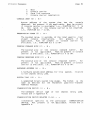
INTRODUCTION
Certain maintenance functions need to be performed remotely at a low
level in the overall network architecture. These are functions that
cannot depend on hiqh level software being operational in the system
being maintained.
In the context of this specification, low level implies direct usage
of data link services.
High level means such network functions as
routing and end-to-end, virtual circuit type protocols, both of which
are also users of data l i n ~services. This specification assumes that
only a minimal level of dara link services are available to support
maintenance operations, and that these maintenance operations provide
a base on which any higher level functions can be built.
This document describes the structure, functions, interfaces, and
protocols needed for low level maintenance. DNA is the model on which
DECnet implementations are based. A DECnet network is a family of
software modules, data bases, and hardware components used to tie
DIGITAL systems together for resource sharing, distributed computation
or remote system communication.
DNA is a layered structure. Modules in each layer perform distinct
functions.
Modules within a single DNA layer (but typically in
different computer systems) communicate using specific protocols.
Modules in different layers (but typically in the same computer
system) interface using subroutine calls or a system-dependent method.
In this document interfaces are described in terms of calls to
subrout ines.
This document assumes that the reader is familiar with computer
communications and DECnet. The primary audience consists of those who
implement DECnet
systems
or
other
systems
under
different
architectures,
but requiring the same functions.
However, the
document may be useful to anyone interested in the details of DECnet
structure. The other current DNA functional specifications are:
DNA Data
-
Access Protocol (DAP) Functional
5.6.0, Order No. AA-K177A-TK
Specification,
Version
DNA Digital
-
Data
Communications
Message
Protocol
(DDCMP)
Functional Specification, Version 4.1.0, Order No. AA-K175A-TK
DNA Ethernet Data Link Functional
-
Specification, Version
1.0.0,
Order NO.=Y!~~A-TK
DNA Ethernet
-
Node Product Architecture
1.0.0, Order No. AA-X440A-TK
DNA Network Management Functional
Order No. AA-X437A-TK
DNA Network
-
Specification,
Specification,
Services Protocol Functional
4.0.0, Order No. AA-X439A-TK
Version
Specification,
Version
4.0.0,
Version
Page 7
Introduction
DNA Routing Layer Functional Specification, Version
-
2.0.0,
Order
NO. AA-X435A-TK
DNA Session Control Functional Specification, Version 1.0.0, Order
NO. AA-K182A-TK
The Ethernet - A- Local Area Network - -Data Link Layer and Physical
Layer
Specifications, Version
Xerox), Order No. AA-K759B-TK
2.0, (Digital,
Intel,
and
-
The DECnet DIGITAL Network Architecture (Phase I V ) General Description
(Order No.
AA-N149A-TC)
provides an overview of the network
architecture and an introduction to each of the DNA functional
specifications.
1.1
Functional Description
Low level maintenance functions are divided into three categories.
Operation within any category depends on the operability o f at least
part of the preceding category. The categories are:
1.
Communications test
2.
System console
3.
System load/dump
Each of these functions can be viewed either from the active or
passive end.
The active end is the one that is driving the
maintenance function and the passive end is the one that
is
responding.
Communications test determines i f the data link communications path is
operative.
System console provides low level access to a system for the functions
of:
.
.
.
.
Identify processor
Read data link counters
Boot system
Console carrier
The console carrier is a general purpose console input/output channel.
It provides a common communication mechanism to allow remote access
regardless of console command specifics.
Page 8
~ntroduction
System load/dump copies the contents of processor memory to or from
remote system.
a
Throughout this document, the term boot is used to mean the process of
causing a system to initialize itself. Initialization may include
loading system memory. A boot command is a cause. The term load is
used to mean the Drocess of transferring a system image into processor
memory from some source. This is one potential effect of a boot
command.
The source of major interest in this specification is a
remote system, accessed via a communication channel.
1.2
Design Scope
The low level maintenance operations require certain characteristics
to be present, attempt to meet certain goals, and lack some features
that are not within the scope of the design.
1.2.1
Requirements
The
maintenance
characteristics:
.
.
.
.
.
1.2.2
operation
design
must
have
The functions previously mentioned must
design.
the
be
included
following
in
the
Active and passive sides of maintenance operations can be
implemented and used independently. The three categories of
maintenance operations are inter-dependent only in simple,
clearly defined ways.
Effects of errors (such as operator errors, protocol errors,
and hardware errors) are minimized, always leaving a system in
a well defined state.
I t must be compatible
loopback protocol.
with
Implementations may select
particular product need.
inter-company
subsets
of
standard
functions
Ethernet
based
on
Goals
The maintenance
characteristics:
.
operation
design
tries
to
have
the
Functions and protocols are upward compatible with
Maintenance Operation Protocol (MOP) version 2.1.
following
the
DNA
Page 9
Introduction
.
.
.
.
Algorithms, particularly those found in memory-only systems,
are
processing
and
memory
efficient.
Communications
efficiency is a secondary goal.
In the specific case of
down-line load and UD-line dump, overall speed of operation is
an important goal.
Extensible to accommodate newly
modification of current functions.
developed
Operates independently of
the
underlying
mechanism (e.g. DDCMP, Ethernet, etc.).
No complex algorithms or data bases.
the smallest systems.
Minimal
The maintenance operation design does not try to
characteristics:
.
.
2
have
functions
or
communication
state
the
kept
in
following
Isolation of components that have failed in a failing system.
System security in the low level maintenance functions.
MODELS
This section describes the relationship of the low level maintenance
operations to other network layers and modules.
Although this
specification primarily relates the maintenance operations to DNA, the
same
relationships
can
also be applied within other network
architectures, such as the DIGITAL System Communication Architecture.
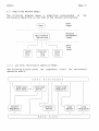
2.1
Relationship to DIGITAL Network Architecture
The maintenance operations reside in the DNA Network Management Layer.
They are direct users of the DNA Data Link Layer. The other DNA
layers are not required in the support of the low level maintenance
operations unless such services as remote file access are to be used.
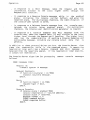
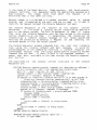
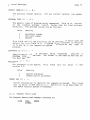
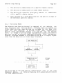
The following diagram shows the overall
layering of DNA.
A later
diagram shows the simplified model that is applicable to the low level
maintenance operations.
Page 10
Mode 1s
1
I---->
1
User Modules
............................
I
I
1 Network Application Modules
- - 1 ................................
I
I
v
v
I
I
I
1 ---- >
I
I
Session Control Modules
.......................................
I
I
1 ------ '
I
I
v
I
I I
' I
I
I
I
I
1
I
NOTE
Horizontal arrows show direct access for control and
observation of parameters, counters, etc. Vertical
arrows show interfaces between layers for normal user
operations such as file access, down-line load, and
logical link usage.
Each layer in DNA consists of functional modules and protocols.
Generally, modules use the services of the next lower layer. In this
document, the service relationship is demonstrated in the way the
interfaces are modeled, as calls to subroutines.
Note that the
Network Management Layer interfaces directly with each of the lower
Models
Page 11
layers.
Also, the layers above Session Control interface directly
with it. For this reason the upper three layers are sometimes
referred to as the "end user."
Modules of the same type in the same layer communicate with each other
to provide their services. The rules governing this communication and
the messages required constitute the protocol for those modules.
Messages
are typically excnanged between equivalent modules in
different nodes. However, equivalent modules within a single node can
also exchange messages.
A brief description of each layer follows in order from the highest to
the lowest layer:
User Layer. The highest layer, the User Layer supports user
services and programs. Programs such as the Network Control
Program, which interfaces with the Network Management Layer,
and file transfer programs, which interface with the Network
Application Layer, reside in the User Layer.
Network Management Layer. The Network Management Layer is the
only one that has direct access to each lower layer for
control purposes. Modules in this layer provide user control
over and access to network parameters and counters. These
modules also perform UD-line dumping, down-line loading, and
testing functions.
Network Application Layer. Modules in the Network Application
Layer support network functions, such as remote file access
and file transfer, used by the User and Network Management
Layers.
Session Control Layer.
The Session Control defines the
system-dependent aspects of logical link communication, which
allows messages to be sent from one node to another in a
network.
Session Control functions include name-to-address
translation, process addressing, and, in some systems, process
activation and access control.
End Communication Layer. The End Communication Layer defines
the system-independent aspects of logical link communication.
Routing Layer. Modules in the Routing Layer route messages,
called packets, between source and destination nodes.
Data Link Layer. The Data Link Layer defines the protocol
concerning data integrity and physical channel management.
Physical Link Layer. The Physical Link Layer encompasses a
part of the device driver for each comrnunications device plus
the communications hardware itself.
The hardware includes
interface devices, modems, and the communication lines.
Mode 1s
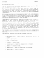
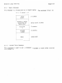
2.2
Page 1 2
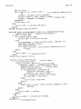
Simplified Network Model
The following diagram shows a simplified relationship
of
maintenance operations to the rest of the network architecture.
------
User
Layer
I User I
...........
I
.
the
.
.
.
.
.
.
.
.
.
.
.
.
.
.
.
I
-------------
Network
Management
Layer
1 Maintenance 1
I Operations I
-------------
.........
1
------1
i
2.2.1
-------
DDCMP
i
.
1
.
I
I
I
I
1
I
1
---------i Ethernet
I
..............
--------
i
1
------I Other I
.
Data
Link
Layer
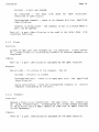
Low Level Maintenance Operation Model
The following diagram shows
operation module.
the
components
within
the
maintenance
Models
Page 13
Requesters are the processes responsible for initiation of maintenance
operations.
This can be done either at higher level user request, or
because of information obtained from a lower level.
Requesters are
the active side of a maintenance operation.
Servers are the processes that respond to maintenance requesters.
They are the passive side of a maintenance operation. Servers should
not try to do more than they are capable of. For example, it is not
acceptable to always volunteer.to load every system that requests it
and then take too long to get done because the local resources are
overextended.
The diagram shows servers and requesters as separate to represent
their functional independence.
In an implementation that supports
multiple servers and/or requesters that use the same protocol type,
they may have to be more closely coupled so that messages received
through the data link are properly demultiplexed. Also, servers and
requesters that allow multiple users must further demultiplex messages
to the proper user processes.
the
The Dump/Load Data Base contains default information that
Dump/Load Server uses to fill in necessary values in incomplete
requests.
Lines to the top of processes indicate flow of the control data that
initiates processing.
Lines to the side indicate Network Management
control. The double horizontal line indicates data base access.
3
INTERFACES
The following sections describe the interfaces related to maintenance
operations.
The function descriptions are in terms of subroutines
with input and output arguments.
These subroutines are to be
understood
as
abstract,
functional
descriptions.
Actual
implementations may vary, for example in synchronization techniques,
as long as they provide the same functions.
References to buffers in all of the following subroutine descriptions
assume a buffer descriptor containing buffer address, maximum buffer
length, and, if applicable, length of information in buffer.
3.1
Data Link Interface
Maintenance operations can be performed over communication channels
provided by different data link disciplines. All of the potential
data link user interfaces are abstracted into the functions required
for maintenance operations.
This section describes that interface.
This section is included to define exactly what services a data link
must provide so that the low level maintenance functions can be
performed. It is an abstract representation of all possible data link
interfaces, in terms that are directly applicable to low level
Page 14
Interfaces
.
.
maintenance operations.
From the perspective of maintenance operations, there
link configurations: ~oint-to-pointand multiaccess.
Point-to-point data links are those where there is
the each end of a loqical channel. T r a n s i t s and
between these two nodes. Multipoint is treated as
the sense that each logical channel (tributary) is
independently.
;
are
two
data
a single node on
receives are always
point-to-point, in
identified and used
Multiaccess data 1,inks are those where the number and identification
of all adjacent nodes are not necessarily known. On multiaccess data
links, node identification must accompany transmit and
receive
requests.
Additionally, multiaccess data links may provide multicast
service for communications with a class of nodes.
Independently of configuration, some data links may allow concurrent
operation of both normal and maintenance traffic. Others may allow
maintenance traffic only in a mode that excludes normal traffic.
This interface assumes that all data links offer the same basic
services, framing and error checking. The data link frames messages
and provides the length of received messages. Messages are sent and
received in the order they were offered by the sender. Messages that
the data link delivers to the receiver have been checked for bit
errors.
It is possible for messages tu be lost with no notification
to either sender or receiver.
The interface function descriptions refer to data link configuration
and maintenance exclusiveness as necessary to indicate differences o f
operation.
The Data Link Interface contains the following functions:
.
Maintenance-check - - check to see i f
needed.
maintenance
service
.
Open - - open a port.
.
Close -- close a port.
.
Transmit -- send a frame.
,
Transmit-pol1 - - check for completion of a Transmit.
.
.
.
Receive - - receive a frame.
Receive-poll - - check for completion of a Receive.
Receive-abort - - abort a Receive.
is
Interfaces
Page 15
Function:
is needed.
Checks the channel to see if maintenance service
Applicable only on exclusive maintenance channels.
Inputs:
Channel-id. - the unique identification of the channel to check.
Outputs:
Return-code - the status of the request.
One of:
Running normally - the channel is running or attempting to run
normal user traffic.
Maintenance needed - the
traffic.
channel
wants
to
run
maintenance
Unrecognized channel - there is no channel with the
identification.
Channel in wrong state - the channel is not in a
the check can be made.
3.1.2
specified
state
where
Open
Funct ion:
Opens a port so that the user can transmit and receive frames.
Inputs:
Channel-id - the unique identification of the channel on which the
port is to be opened.
Pad - an indication that the data link is to use its own standard
padding technique if padding is necessary. Maintenance operations
use this option, when available, for all but the multiaccess
channel loop protocol.
Id-list - a list of identification data, such as protocol types or
multicast addresses, that identify this user of the data link.
Data link specific and applicable only on concurrent maintenance
channels.
For example, in the Ethernet Data Link this abstract
id-list function is accomplished using the Ethernet Data Link
Open, Enable-protocol, and Enable-multicast functions.
Outputs:
Return-code - the status of the request.
One of:
Interfaces
Page 16
Success - a port was opened.
No resources - the data
resources to open a port.
link
does
not
have
Unrecognized channel - there is no channel with the
identification.
sufficient
specified
Channel in wrong state - the channel is not in a state where a
port c a n b e opened.
Port-id - a port identification to be used in the other data
interface functions.
3.1.3
link
Close
Function:
Closes an open port and releases all its resources. A port cannot
be closed unless all outstanding transmit or receive requests are
completed.
Inputs:
Port-id - a port identification assigned by the Open function.
Outputs:
Return-code - the status of the request.
One of:
Success - the port is closed.
Unrecognized port - there is no open port with
identification.
the
Calls outstanding - there are uncompleted transmit or
requests outstanding on the port.
3.1.4
specified
receive
Transmit
Funct ion:
Queues a frame to be transmitted. The user tests for completion
by using Transmit-poll. Transmission of a frame always succeeds
or fails within such a small amount of time that an abort function
is not necessary.
Inputs:
Por't-id
- a port identification assigned by the Open function.
Interfaces
Page 17
This
Destination-address - the address of the frame destination.
can
be either a physical address or a multicast address.
~pplicableonly on multiaccess channels.
Protocol-type - a protocol type to identify the data at the
receiving system.
Applicable only on concurrent maintenance
channels.
Input-buffer - a buffer containing the data to be sent. Until the
request is completed, the user must not disturb the contents o f
the buffer.
Outputs:
Return-code - the status of the request.
One of:
Request accepted - the data link will attempt to transmit the
frame.
Notification of completion is via the Transmit-poll
function.
No resources - the data link does not
resources to queue a transmit for this port.
have
Unrecognized port - there is no open port with
identification.
sufficient
the
Channel in wrong state - the channel is not in a
it can send a frame.
specified
state
where
Function:
. .
Checks for the completion of a transmit request.
The data l i n r :
transmits frames in the order in which the user submits them.
Successful completion of this function implies only that the local
transmitter believes that it sent the frame.
It does not
necessarily imply that the destination received it.
Inputs:
Port-id - a port identification assigned by the Open function.
Outputs:
Return-code - the transmit request for this port.
One of:
Not complete - no transmit for this port is done.
None outstanding - there are no outstanding transmits for this
port.
Interfaces
Page 18
Transmit successful - a
transmitter.
frame
successfully
left
the
local
Transmit failed - the local transmitter could not transmit the
frame.
Unrecognized port - there is no open port with
identification.
the
Channel in wrong state - the channel is not in a
it can send a frame.
Input-buffer - the
function.
3.1.6
buffer
that
was
supplied
in
specified
state
the
where
Transmit
Receive
Funct ion:
Queues a buffer to receive a frame. On multiaccess or concurrent
maintenance channels, the receive is filtered according to the
id-list established in the Open function.
Inputs:
Port-id - a port identification assigned by the Open function.
Output-buffer - a descriptor of a buffer to contain
frame.
the
received
Outputs:
Return-code - the status of the request.
One of:
Request accepted - i f a message is received for the specified
port, the data link will put it into the buffer. Notification
of completion is via the Receive-poll function.
No resources - the data link does not
resources to queue a receive for this port.
have
Unrecognized port - there is no open port with
identification.
Channel in wrong state - the channel is not in a
it can receive a frame.
sufficient
the
specified
state
where
Interfaces
Page 19
Function:
Check for the completion of a receive
gives received frames to the user
arrived.
request.
The data link
in the order in which they
Inputs:
Port-id - a port identification assigned by the Open function.
Outputs:
Return-code - the status of the receive request.
One of:
Not complete - no outstanding receive for this port is done.
None outstanding - there are no outstanding receives for
port.
thi:
Receive successful - a frame was
the buffer.
into
successfully
received
Receive with overrun - a frame was successfully received,
had to be truncated to fit into the buffer.
Receive aborted - the user cancelled the receive request
the Receive-abort function.
Unrecognized port - there is no open port with
identification.
Channel in wrong state - the channel is not in a
it can receive a frame.
the
but
witl-
specified
state
where
Destination-address - the address to which the received frame was
addressed. Applicable only on multiaccess channels.
Source-address - the address from which the received
Applicable only on multiaccess channels.
frame
Protocol-type - the protocol type from the received
Applicable only on concurrent maintenance channels.
came.
frame.
Output-buffer - the received data.
Function:
Aborts all outstanding receive requests. The buffers are returnee
via the Receive-poll function. They may be returned as aborted o r
Page 20
Interfaces
as normally completed.
Inputs:
Port-id - a port identification assigned by the Open function.
Output-buffer - a descriptor of a buffer for a pending receive.
outputs:
Return-code - the status of the request.
One of:
Success - the request is now complete.
Unrecognized port - there is no open port with
identification.
the
Unrecognized buffer - the specified buffer is not
the specified port.
3.2
specified
queued
for
User Level Maintenance Operation Interface
This section describes the functions available to the maintenance
operation
user.
The descriptions relate each function to its
respective component in the maintenance operation
model.
The
functions are divided into three grouos:
Dump/Load Functions
.
.
Loop Test Functions
Remote Console Functions
The Dump/Load Functions are:
.
.
.
.
.
Force-load -- load a remote system.
Force-load-poll - - check for completion of a Force-load.
Load-self - - load the local system.
Load-self-poll -- check for completion of a Load-self.
Force-dump -- dump a remote system.
.
Force-dump-poll
.
Dump-self -- dump the local system.
--
check for completion of a Force-dump.
Interfaces
.
Page 21
Dump-self-poll - - check for completion of a Dump-self.
The Loop Test Functions are:
.
.
Loop-direct -- loop test direct with another system.
Loop-assisted - - loop test with third-party assistance.
.
Loop-poll
.
Loop-abort -- abort a loop.
--
check for completion of a loop.
The Remote Console Functions are:
Request-poll - - check for remote execution control request.
Identify-self - - send system identification.
Boot -- force remote system to load.
Read-identity -- read remote identity.
Read-identity-poll
--
check for completion of a Read-identity.
Read-counters - - read remote data link counters.
Read-counters-poll - - check for completion of a Read-counters.
Reserve-remote-console -- reserve remote system's console.
Release-remote-console -- release remote system's console.
Send-console-command
console. *
--
send
command
message
to
*
remote
Console-response-poll -- check for completion of Send-consolecommand. *
Send-console-response - - send console response data to
command Console Requester. *
remote
Console-abort -- abort a pending console function.
*
3.2.1
Requires that the Console Server be reserved.
Dump/Load Functions
The following functions are performed
Requester or the Dump/Load Server.
by
either
the
Dump/Load
Page 22
Interfaces
Function:
Forces a down-line load of the system on the specified channel.
This function is a call to the Dump/Load Server. It is a server
function rather than a requester function since the server is the
component that will actually service the load request that is
forced from the target system.
The Force-load function queues the request. The user
completion with the Force-load-poli function.
checks
for
Inputs:
Channel-id - the unique identification of the channel over which
the load is to be performed. If not specified, the channel-id
from the Dump/Load Data Base is used.
Destination-address - the identification of the target system. I f
not
specified but needed, the destination-address from the
Dump/Load Data Base is used.
Destination-address is needed on
multiaccess channels.
NOTE
Either the channel-id or the destination-address
must be included in order to identify the target
system.
If
both
are
i nc luded ,
the
destination-address is used as the data base
search key to find other values in the Dump/Load
Data Base.
Load-file - the identification of the file that is to be down-line
loaded into the target system.
If not specified, the file
identification from the Dump/Load Data Base is used.
Secondary-loader - the identification of the file that contains
the secondary loader program to use. I f not specified but needed,
the file identification from the Dump/Load Data Base is used.
Tertiary-loader - the identification of the file that contains the
tertiary loader program to use. I f not specified but needed, the
file identification from the Dump/Load Data Base is used.
Outputs:
Return-code - the status of the request.
Request accepted
Notification
of
function.
-
the load
completion
One of:
process
is via
will be initiated.
the Force-load-poll
Interfaces
Page 23
No resources - the Dump/Load Server does not
resources to queue the request.
have
sufficient
Unrecognized channel - there is no channel with the
identification.
specified
Channel in wrong state - the channel is not in a state where a
load can be done.
~eceipt-number- a receipt number to identify this request in
Force-load-poll function.
the
Function:
Checks for completion of a pending Force-load
function is a call to the Dump/Load Server.
function.
This
Inputs:
Receipt-number - the receipt number
function to identify the request.
assigned
by
the
Force-load
Outputs:
Return-code - the status of the request.
One of:
In process - the load is proceeding.
Success - the down-line load completed successfully.
Force boot failed - could not force the target system to enter
a booting state.
Memory load error - the target system reported
attempting to deposit part of the load.
an
error
in
File open error - could not open one of the files.
Invalid file contents - invalid data in one of the files.
File 1/0 error - 1/0 error reading one of the files.
Channel communication error - error in transmit or receive
the channel.
on
Channel protocol error - error in protocol usage by the target
system.
Unrecognized channel - there is no channel with the
identification.
specified
Page 24
Interfaces
Unrecognized target - the Dump/Load Data Base was needed
did not contain an entry for the specified target.
but
Channel in wrong state - the channel is not in a state where a
load operation can be done.
File-indicator - the indication of which file a file error relates
to. Not meaningful for non-file related errors. One of:
Load file
Secondary loader
Tertiary loader
Function:
Requests a down-line load of the local system.
This is the
communications channel equivalent of a system loading itself from
local mass storage. Note that only one self-load can be in
progress at a time. I f a second request is made before a previous
one completes, the new request simply replaces the old one.
This
function is a call to the Dump/Load Requester.
Inputs:
Channel-id - the unique identification of the channel on which the
load is to be done.
Destination-address - the identification of the systen-1 that is to
assist in the load. Applicable only on multiaccess channels. I f
the address is applicable but not specified, the load will be
taken from whatever system is able to help (for further details,
see operation section).
System-processor - the processor type of the local system. I f not
specified, the assisting system must assume a type. Defined types
are in Appendix A.
Software-id - the type of software desired.
assisting system must assume a type.
I f not specified, the
Zero
Other-info - further, implementation-specific information.
or more other-info parameters may be included, each consisting of:
.
identification
of
the
parameter.
Parameter-id
Identifications are related to the standard parameters (e.g.
communications-processor,
system-bus)
on
an
implementation-specific basis.
Parameter-value - the value of the parameter.
Interfaces
Page 25
Outputs:
Return-code - the status of the request.
One of:
Request accepted - the load process will be initiated.
Notification of completion is via the Load-self-poll function.
Unrecognized channel - there is no channel with the
identification.
specified
Channel in wrong state - the channel is not in a state where a
load can be done.
Funct ion:
Checks for completion of the pending Load-self
function is a call to the Dump/Load Requester.
Inputs:
function.
This
None.
Outputs:
Return-code
-
Requesting
the status of the request.
-
One of:
the load is being requested.
In p r o c e s s - t h e load is proceeding.
Successful - the load completed successfully.
Failure - the load failed.
Start-address - on successful load completion, the starting memory
address of the loaded image.
Local-address - the network address that the local
use. Not returned if not received.
Local-name - the network name that the local
Not returned i f not received.
system
system
is
is
to
to
use.
Host-address - the network address of the host that this system is
to use. Not returned i f not received.
Host-name - the network name of the host that this
use. Not returned if not received.
Host-date-time - the date
returned if not received.
and
time
at
the
host
system
system.
is
to
Not
Page 26
Interfaces
Function:
Forces an up-line dump of the system on the specified channel.
This function is a call to the Dump/Load Server. It is a server
function rather than a requester function since the server is the
component that will actually dump the target system.
The Force-dump function queues the request. The user
completion with the Force-dump-poll function.
checks
for
Inputs:
Channel-id - the unique identification of the channel over which
the dump is to be performed. If not specified, the channel-id
from the Dump/Load Data Base is used.
Destination-address - the identification of the target system. I f
not
specified but needed, the destination-address from the
Dump/Load Data Base is used.
Destination-address is needed on
multiaccess channels.
NOTE
Either the channel-id or the destination-address
must be included in order to identify the target
If
both
are
included,
the
system.
destination-address is used as the data base
search key to find other values in the Dump/Load
Data Base.
Dump-file - the identification of the file that is to be up-line
dumped into on the target system. If not specified, the file
identification from the Dump/Load Data Base is used.
Dump-address - the memory address in the target system to begin
dumping from.
I f not specified and not obtainable from the
target, the value from the Dump/Load Data Base is used.
Dump-count - the number of memory units to dump. Memory units are
whatever is customary for the processor type: usually, but not
necessarily, eight-bit bytes.
If not
specified,
and
not
obtainable from the target, the value from the Dump/Load Data Base
is used.
Outputs:
Return-code
-
the status of the request.
Request accepted
Notification
of
function.
-
the dump
completion
One of:
process
is via
will
the
be
initiated.
Force-dump-poll
Interfaces
Page 27
No resources - the Dump/Load Server does not
resources to queue the request.
Unrecognized destination - there is no
specified identification.
have
destination
Unrecognized channel - there is no channel with the
identification.
sufficient
with
the
specified
channel in wrong state - the channel is not in a state where a
dump can be done.
Receipt-number - a receipt number to identify this request in
Force-dump-poll function.
the
Function:
Checks for completion of a Force-dump function.
Inputs:
Receipt-number - the receipt number
function to identify the request.
assigned
by
the
Force-dump
Outputs:
Return-code - the status of the request.
In process
-
One of:
the dump is proceeding.
Success - the up-line dump completed successfully.
Remote dump failed - could not force the target system to
cooperate. The higher level may be able to remedy this with a
Force-load.
Memory read error - the target system
reading memory.
File open error
-
reported
an
error
in
could not open the dump file.
Invalid file contents - invalid data in the dump file.
File 1/0 error - 1/0 error reading or writing the dump file.
Channel communication error - error in transmit or receive
the channel.
Channel protocol error
system.
-
on
error in protocol usage by the target
Interfaces
Unrecognized channel - there is no channel with the
identification.
Page 28
specified
Unrecognized target - the Dump/Load Data Base was needed,
did not contain an entry for the specified target.
but
Channel in wrong state - the channel is not in a state where a
dump operation can be done.
Funct ion:
Requests an up-line dump of the local system.
This is the
communications channel equivalent of a system dumping itself to
local mass storage. Note that only one self-dump can be in
progress at a time. I f a second request is made before a previous
This
one completes, the new request simply replaces the old one.
function is a call to the Dump/Load Requester.
Inputs:
Channel-id - the unique identification of the channel on which the
dump is to be done.
Destination-address - the identification of the system that is to
assist in the dump. Applicable only on multiaccess channels. I f
applicable but not specified, the dump will go to whatever system
is able to help.
Dump-address - the address in local memory at which the dump is to
begin.
I f not specified, the assisting system must assume an
address.
Dump-count - the number of memory units to dump. Memory units are
whatever is customary for the processor type; usually, but not
necessarily, eight bit bytes. I f not specified, the assisting
system must assume a count.
System-processor - the processor type of the local system. If not
specified, the assisting system must assume a type. Defined types
are in Appendix A.
Software-id - the type of software that was running.
If not
specified, the assisting system must assume a type. Defined types
are in Appendix A.
Other-info - further, implementation-specific information.
Zero
or more other-info parameters may be included, each consisting of:
identification
of
the
parameter.
Parameter-id
Identifications are related to the standard parameters (e.9.
comrnunications-processor,
system-bus)
on
an
Interfaces
Page 29
implementation-specific basis.
Parameter-value - the value of the oarameter.
Outputs:
Return-code - the status of the request.
One of:
Request accepted - the dump process will be initiated.
Notification of completion is via the Dump-self-poll function.
Unrecognized channel - there is no channel with the
identification.
specified
Channel in wrong state - the channel is not in a state where a
dump can be done.
Function:
Checks for completion of the pending Dump-self
function is a call to the Dump/Load Requester.
Inputs:
function.
This
None.
Outputs:
Return-code - the status of the request.
One of:
Requesting - the dump is being requested.
In process - the dump is proceeding.
Successful - the dump completed successfully.
Failure - the dump failed.
Loop Test Functions
3.2.2
The specific goals in the design of the Loop Test functions are:
.
.
Provide for all forms of loop test that are
diagnose a system's ability to communicate.
necessary
to
Allow each system to assume the responsibility to diagnose its
own ability to communicate.
Interfaces
.
,
Page 30
For multiaccess channels, allow a network management system to
diagnose some other system's ability to communicate.
Minimize processing and memory requirements,
systems other than the requesting system.
particularly
in
The realization of these goals is differerii: for multiaccess channels
and point-to-point channels, since multiaccess channels have a broader
communication ability.
On a point-to-point channel, a system using the Loop Test functions on
its own behalf and having all of them available can ascertain its
ability to communicate with the system on the other end of the
channel.
For multiaccess channels, the Loop Test functions are modeled after
the Ethernet standard. See Appendix E or the Ethernet Specification,
Version 2.0, for a detailed description.
Some multiaccess channels may support the concept of a generic
loopback assistant.
These are systems that are willing to assist in
some forms of
multiaccess
loopback
testing.
The
following
descriptions
refer to these systems as the loopback assistant
multicast group.
The amount of the Loop Test interface t h c ~is implemented can cover
the full ranqe from none at all to full capability. However, those
systems that do not
provide
the
full
interface
capability
proportionately limit their capacity for self diagnosis and become
more dependent on some centralized test facility.
The followinq functior-,Sare oil calls to the Loop Requester.
Function:
Determine
possible.
if
direct
communication
with
a
remote
system
is
Inputs:
Channel-id - the unique identification of the channel on which the
loop is to be done.
Destination-address - the identification of the system that is to
be looped to.
Applicable only on multiaccess channels. If
applicable and not included, the loopback
assistant
group
multicast address is used.
Interfaces
Page 31
Input-buffer - a buffer containing the data to be looped.
Output-buffer - a buffer to contain the looped back data. If
present, the looped back data is not returned to the user.
not
Outputs:
Return-code - the status of the request.
One of:
Request accepted - the loop will be attempted.
Unrecognized channel - there is no channel with the
identification.
Channel in wrong state - the channel is in
loop cannot be done.
a
specified
state
Receipt-number - the request identification used in the
or Loop-abort function to identify this request.
where
a
Loop-poll
Function:
Determine i f some other system can communicate with the specified
remote system. Applicable only on multiaccess channels.
Inputs:
Channel-id - the unique identification of the channel on which the
loop is to be done.
Destination-address - the identification of the system that is to
be looped to.
The destination-address cannot be a multicast
address.
Assistant-address - the identification of the third party system
to assist in the test. The address .cannot be a multicast address.
Assistance-level - the amount of assistance desired:
transmit - the assistant station is only to relay the request,
the request is to be returned from the destination system.
receive - the assistant station is only to relay the
the request is to be sent to the destination station.
full - the assistant station is
reply.
to
relay
both
reply,
request
Input-buffer - a buffer containing the data to be looped.
and
Page 32
Interfaces
Output-buffer - a buffer to contain the looped back data. If
present, the looped back data is not returned to the user.
not
Outputs:
Return-code - the status of the request.
One of:
Request accepted - the loop will be attempted.
Unrecognized channel - there is no channel with the
identification.
Channel in wrong state - the channel is in
loop cannot be done.
a
state
Receipt-number - the request identification used in the
or Loop-abort function to identify this request.
specified
where
a
Loop-poll
Function:
Used to poll for completion of a Loop-direct or Loop-assisted.
nputs:
Receipt-number - the request
request by the Loop function.
identification
assigned
to
this
Compare error - the data came back, but it did not match
was sent.
what
Outputs:
Return-code - the status of the operation.
One of:
Not complete - the loop is not yet done.
Success - t h e d a t a came back correctly.
Aborted - the request was aborted with a Loop-abort.
Transmit failed - the local transmitter
initial message.
could
not
send
the
Channel communication error - no response was received.
Either the initial message or the response did not arrive.
Responding-address - the identification of the remote system that
satisfied the request.
Applicable only on multicast channels.
For Loop-assisted with transmit assistance, this is the remote
system
address.
For
Loop-assisted
with receive or full
assistance, it is the assistant system address.
Interfaces
Page 33
Output-buffer - the looped back data received, whether correct or
not. Present only if the buffer was furnished on the Loop call.
Function:
Used to abort a Loop-direct or Loop-assisted, for example
user decides that the reply has taken too long.
if
the
Inputs:
Receipt-number - the request identification assigned
request by the Loop-direct or Loop-assisted function.
Outputs:
to
this
none.
Remote Console Functions
3.2.3
There is an aspect of the Console Server operational model that
affects the user interface in a way that must be explained here. This
is the relationship between data access functions and
control
functions.
.
.
Data access - - these functions involve parameters (for example
Read-identity). The model assumes that the Console Server has
necessary access abilities without higher level involvement.
Control -- these functions involve changing the flow of
execution of a processor (for example, Boot). The model
assumes that the Console Server cannot do this directly.
The
higher level must therefore poll the Console Server for this
type of request and the information needed to honor it.
Most of the remote console functions are calls to the Console
Requester.
Console Requester operations are of two types, those that
require exclusive access to the remote console and those that do not.
Unless otherwise noted, the
Console Requester.
following
functions
are
calls
to
the
Function:
These
Checks to see i f certain remote requests have been made.
that
directly modify local system processor
are
requests
Page 34
Interfaces
execution. Remote requests are not queued: only the most recent
is available.
Each remote request can be read only once. The
higher level process is responsible for polling often enough to
ensure a minimum number of lost requests.
This is a call to the Console Server.
Inputs:
Channel-id - the unique identification of the channel on which
check for remote requests.
to
Outputs:
Return-code - the status of the request.
One of:
No requests - no remote requests have been received.
Request read - a remote request has been returned.
Request truncated - a console command request
received; however all of the command data was lost.
has
Unrecognized channel - there is no channel with the
identification.
specified
Channel in wrong state - the channel is not in a
the request can be received.
state
been
where
Request-type - the type of request made by the remote system.
of:
One
Boot
Console command
Boot-server - for a boot request, an indication
system to be used to honor the request. One of:
Default-server - the system that this
use.
system
of
the
would
server
normally
Command-source - the system involved in this request.
Boot-device - for a boot request, an indication of the device this
system is to use to honor the request. One of:
Default-device - the device that this
use.
system
would
normally
Specified-device - the device specified by the command source.
Device-id - for specified-device, identification of the device
boot from.
to
Interfaces
Page 35
Verification-code - for a boot request, the
verification code sent by the requesting system.
4
or
Source-address - the identification of the system that
request. Applicable only on multiaccess channels.
8
byte
sent
the
Command-data-buffer - for a console command, the buffer containing
the command message.
Command-break-flag - for a console command, indicates when a break
condition is to precede the command message to the console.
Function:
Causes a system identification message to be sent.
This is a call to the Console Server.
Inputs:
Channel-id - the unique identification of the channel on which
send the identity.
to
Destination-address - the identification of the
destination
system.
Applicable only to multiaccess channels. I f applicable
and not present, the identity message will be sent to the remote
console multicast group.
Outputs:
Return-code - the status of the request.
One of:
Success - identity sent.
Transmit failed - the data link failed to send the message.
Unrecognized channel - there is no channel with the
identification.
Channel in wrong state - the channel is not in a
the request can be received.
3.2.3.3
specified
state
where
Boot
Function:
Force the remote processor to initialize itself.
his may cause
the system to reload its system image either locally or remotely.
Page 36
Interfaces
Channel-id - the unique identification of the channel on which
send the boot command.
Destination-address - the identification of the
system. Applicable only to multiaccess channels.
to
destination
Verification code - a code to send to the remote system so it will
honor the request. The code can be either 4 or 8 bytes long. I f
it is 4 bytes, no additional parameters can be sent.
If
additional parameters are to be sent, the code must be 8 bytes
long.
Boot-server - for a boot request, an indication
system to be used to honor the request. One of:
Default-server - the system that this
use.
system
of
the
would
server
normally
Cornhand-source - the system involved in this request.
Boot-device - for a boot request, an indication of the device this
system is to use to honor the request. One of:
Default-device - the device that this
use.
system
would
normally
Specified-device - the device specified by the command source.
Device-id - for specified-device, identification of the device
boot from.
to
Software-id - the software that the remote system is to load.
Outputs:
Return-code
-
the status of the request.
One of:
Success - request sent.
Transmit failed - the local transmitter could not transmit the
request.
Unrecognized channel - there is no channel with the
identification.
Channel in wrong state - the channel is not in a
the boot can be done.
specified
state
where
Interfaces
3.2.3.4
Page 37
Read-identity
Funct ion:
Reads the identity of the specified system.
Inputs:
Channel-id - the unique identification of the channel on which
read the identity.
Destination-address - the identification of the
system. Applicable only to multiaccess channels.
to
destination
Outputs:
Receipt-number - the receipt number used in the Console-abort
Read-identity-poll functions to identify this request.
or
Function:
Polls for completion of a Read-identity function.
Inputs:
Receipt-number - the request identification
request by the Read-identity function.
assigned
to
this
Outputs:
Return-code - the status of the request.
One of:
Not complete - the operation is still in process.
Success - identity read.
Transmit failed - the local transmitter could not transmit the
request.
Unrecognized channel - there is no channel with the
identification.
Channel in wrong state - the channel is not in a
the read can be done.
specified
state
where
Level
Maintenance-version - the version number of the Low
Maintenance Operations Architecture that the system is using.
Functions - a list of flags indicating whether or not various
maintenance functions are currently supported on the system. The
possible functions are:
Page 38
Interfaces
LOOP
Dump
Primary loader (can only load secondary loader)
Multi-block loader (can load tertiary loader or system)
Boot
Console carrier
Data link counters
Console carrier reservation
Console-user - the identification of the system that
remote console reserved. Not returned if not received.
has
the
Reservation-timer - the maximum number of seconds that are allowed
with no remote console requests before the reservation expires.
Not returned if not received.
Console-command-size - the maximum allowable size
command message. Not returned if not received.
of
a
console
Console-response-size - the maximum allowable size
response message. Not returned if not received.
of
a
console
Hardware-address - the unique hardware address of the remote
system. This may or may not be the address in use to identify the
system. Not returned if not received.
Communication-device - the device type of the communication
subsystem over which the remote system received the request. Not
returned if not received. Defined types are in Appendix A .
Software-id - the type of software running in the remote system.
Not returned if not received. Defined types are in ~ p p e n d i xA .
System-processor - the processor type of the remote system.
returned if not received. Defined types are in Appendix A.
Not
Data-link-type - the data link mechanism over which the remote
system received the request.
Not returned i f not received.
Defined types are in Appendix A.
Data-link-buffer-size - the size of the data link buffer, which
determines the maximum size MOP message that the station can
accept. It includes all except the DDCMP header.
The default
value is 262 (256 plus the current MOP header size). A server may
ignore this field, so that all requesters must support 262 byte
messages. Not returned if not received.
Other-info - further, implementation-specific information.
Zero
or more other-info parameters may be included, each consisting of:
Parameter-id
identification
of
the
parameter.
Identifications are related to the standard parameters (e.g.,
communication-device, system-processor) on an implementationspecific basis.
Interfaces
Page 39
Parameter-value - the value of the parameter.
3.2.3.6
Read-counters
Function:
Reads the data link counters from the specified system.
Inputs:
Channel-id - the unique identification of the channel on which
read the counters.
Destination-address - the identification of the
system. Applicable only to multiaccess channels.
to
destination
outputs:
Receipt-number - the receipt number used in the Console-abort
Read-counters-poll functions to identify this request.
3.2.3.7
or
Read-counters-poll
Function:
Polls for completion of a Read-counters function.
Inputs:
Receipt-number - the request identification
request by the Read-counters function.
assigned
to
this
outputs:
Return-code - the status of the request.
One of:
Not complete - the operation is still in process.
Success - counters read.
Transmit failed - the local transmitter could not transmit the
request.
Unrecognized channel - there is no channel with the
identification.
Channel in wrong state - the channel is not in a
the read can be done.
specified
state
where
Interfaces
Page 40
Counters - a block of counter information
particular data link (see Appendix B).
as
defined
for
the
Function:
This
Reserves the,remote system console for use by this system.
must be done before the console carrier can be used. The remote
console stays reserved as long as this system makes any console
request before the remote system's reservation timer expires. I f
the remote console reservation timer expiresl this system's
console reservation is lost without notification.
Reservation of a remote console allocates and initializes a
collection of local resourcesl known as a port. Those console
functions,that require a reservation are requested via the port
identification.
Initialization of the port allows the command
node to synchronize the command and response data streams with the
target node's Console Server.
In cases where a remote system console can be accessed over more
than one communication channell it is the responsibility of that
system and the user of the remote console to ensure that there are
no conflicts of control.
Inputs:
Channel-id - the unique identification of the c.hanne1 on which
reserve the remote system console.
Destination-address - the identification ofs the
system. Applicable only to multiaccess channels.
to
destination
Verification code - a code to send to the remote system so it will
honor the request.
outputs:
Return-code - the status of the request.
One of:
Success - request sent.
No resources - this system has insufficient
assign a port for remote console requests.
resources
to
Transmit failed - the local transmitter could not transmit the
request.
Unrecognized channel
identification.
-
there is no channel with the
specified
Interfaces
Page 41
Channel in wrong state - the channel is not in a
the reservation can be made.
state
Port-id - a port identification to be used in the other
Console Interface functions that require a reservation.
where
Remote
Function:
This
Releases this system's access to the remote system console.
provides
an optimization over allowing the remote system's
reservation timer to expire and deallocates the local port
resources.
Note that even though a message cannot be sent to the remote
system, the local resources will still be released. In other
words, from the standpoint of the local system, this function does
not fail.
Inputs:
a
port
identification
Port-id
Reserve-remote-console function.
assigned
by
the
outputs:
Return-code - the status of the request.
One of:
Success - request sent.
Transmit failed - the local transmitter could not transmit the
request.
Unrecognized port - there is no open port with
identification.
the
specified
Channel in wrong state - the channel is not in a state where a
transmit can be done.
Function:
Sends console command data and polls the Console Server of the
target system.
This function is used with no conunand data to
achieve a poll of the target system without sending a conunand.
Inputs:
Interfaces
Port-id - a port identification assigned
console function.
.
by
the
Page 42
Reserve-remote-
Command-break-flag - a logical value, where true indicates that
the data in the command-data-buffer is to be preceeded by a break
condition in the serial byte stream, This is for target system
console implementations with an RS232-C type interface.
Command-data-buffer - a buffer containing command data to be sent
to the remote system. This must not be larger than the maximum
size command the remote system can receive, as indicated through
the Read-identity function.
Response-data-buffer - a buffer to receive data from the remote
system.
This must be at least as large as the maximum size
response the remote system can send, as indicated through the
Read-identity-poll function.
outputs:
Return-code - the status of the request.
One of:
Success - console command accepted for transmission.
Unrecognized port - there is no open port with
identification.
the
specified
Function denied - a previous Send-console-command function was
still pending.
Invalid buffer size - the command buffer is larger than the
target Server allows, or the response buffer is smaller than
the target Server allows.
Receipt-number - the request identification used in the Consoleabort or Console-response-poll functions to identify this request.
Function:
Polls for completion of the Send-console-command function.
Inputs:
Receipt-number - the request identification assigned to the
console-command function.
outputs:
Return-code - the status of the request.
One of:
Send-
Interfaces
Page 43
Pending - the exchange is not yet complete.
Success - console data sent and acknowledged.
Data lost - success, but data was lost during the exchange.
Transmit failed - the local transmitter could not transmit the
request.
command-data-buffer - the buffer which contained the c o m a n d sent
to the remote system. Invalid if pending status is returned.
Response-data-buffer - the buffer with the received response data
from the remote system. Invalid if pending status is returned.
Data-lost-flags - indicators as to the type and reason for the
Data lost return-code, Present only if Data lost code returned.
Any of:
Command-data-lost - a logical value that is true if the
command data in the Console Command And Poll message was lost.
Response-data-lost - a logical value that is true if the
remote console server detected lost console data due to a
buffer overrun or other error condition.
The data in the
response-data-buffer is possibly incomplete.
Receive-data-lost - a logical value that is true i f the
receive-data-buffer was too small to receive all of the data
that was sent.
Function:
Causes a c o n s o l e r e s p o n s e t o be s e n t t o t h e Console
Requester
of
the remote c o m a n d system.
This is a call to the Console Server of the target system. It is
used to respond to remote console requests from the console user.
Inputs:
Channel-id - the unique identification of the channel on which the
response is to be made.
Destination-address - the identification of the command system.
Applicable only to multiaccess channels. If applicable and not
present, the console-user address is implied.
Command-data-lost-flag - a logical value that is true
command data in the received console command was lost.
if
the
Page 44
Interfaces
Response-data-lost-flag - a logical value that is true i f there
was a loss of data in the console response. This is provided for
implementations where the user of the Console Server cannot block
the source of the console output data stream.
Response-data-buffer - a buffer containing data to be sent to the
remote system. This must not be larger than the maximum response
buffer size in the local system id.
Outputs:
Return-code - the status of the request.
One of:
Success - console response data sent.
Invalid buffer size - the buffer is
allows.
larger
than
the
server
Function denied - a previous send-console-response request
still active.
Unrecognized channel - there is no channel with the
identification.
is
specified
Channel in wrong state - the channel is not in the reserved
state or the console carrier protocol has not been enabled.
Invalid destination-address - the supplied destination-address
does not match the console-user address in the local system
ID.
Transmit failed - the local transmitter could not transmit the
request.
Function:
Aborts a pending condole request. Console-abort only affects an
individual request and does not cause any change in console state.
Inputs:
Receipt-number - the number assigned
following requests can be aborted:
to
the
request.
The
Interfaces
Outputs:
3.3
Page 45
None.
Network Management Interface
This section defines the control and
maintenance operations.
observation
functions
for
the
The Network Management Interface functions are:
.
.
.
.
.
Set-state - - enable or disable local maintenance function.
Read-state -- read states of switchable functions.
Add-dump/load-entry - - add a new entry to the
Base.
Remove-dump/load-entry - - Remove an entry from
Data Base.
Dump/Load
the
Data
Dump/Load
Set-dump/load-parameter -- set a dump/load parameter.
.
.
.
Read-dump/load-parameter
.
Read-console-parameter - - read a local console parameter.
Read-dump/load-list - - read the list of dump/load entries.
- - read dump/load parameters.
Set-console-parameter - - set a local console parameter.
Function:
Enables or disables various local maintenance operation
or components.
functions
Inputs:
Channel-id - the unique identification of the
the function state is to be switched.
channel
Function - the function whose state is to be switched.
Console Server - controls whether
respond to any incoming requests.
the
Console
for
which
One of:
Server
will
Dump/Load Server - controls whether the Durnp/Load Server
respond to any incoming requests.
will
Page 46
Interfaces
Dump/Load assistance - controls whether the
will respond to dump or load requests
assistance multicast group.
Durnp/Load Server
to the dump/load
Loop Server - controls whether the Loop Server will respond to
any incoming requests.
Loop assistance - controls whether the Loop Server will
respond to loop requests to the loopback assistance multicast
group.
Remote console reservation - controls whether
system is allowed to reserve the local console.
any
State - the state that the function is to be switched to.
remote
One of:
On - the function is allowed to operate.
Off - the function is not allowed to operate.
Outputs:
Return-code - the status of the request.
One of:
Success - state switched.
Unrecognized channel - there is no channel with the
identification.
specified
Channel in wrong state - the channel is not in a state where a
switch can be done.
Function:
Reads the states of the switchable local maintenance functions.
All of the states are either on or off as described for the
Set-state function.
Inputs:
Channel-id - the unique identification of the channel to read
states for.
Outputs:
Return-code
-
the status of the request.
Success - states read.
One of:
the
Page 47
Interfaces
Unrecognized channel - there is no channel with the
identification.
Channel in wrong state - the channel is not in a
the read can be done.
specified
state
where
Console-state - the state of the Console Server.
Dump/load-state - the state of the Dump/Load Server.
Loop-state - the state of the Loop Server.
Loop-assistance-state - the state of loop assistance.
Remote-console-reservation-state - the
reservations.
state
of
remote
console
Function:
Adds an entry to the Dump/Load Data Base.
Inputs:
Channel-id - the unique identification
identifies the data base entry.
of
the
channel
that
Destination-address - the identification of the target system that
identifies the data base entry.
NOTE
Either the channel-id or the destination-address
must be included in order to identify the target
system.
I f both are
included,
the
destination-
address is used as the data base search key to
find the entry in the Dump/Load Data Base.
Outputs:
Return-code - the status of the request.
One of:
Success - entry added.
Already defined - the Dump/Load Data Base already contains
entry for the specified target.
an
Page 48
Interfaces
Function:
Removes an entry from the Dump/Load Data Base.
Channel-id - the unique identification
identifies the data base entry.
of
the
channel
that
Destination-address - the identification of the target system that
identifies the data base entry.
NOTE
Either the channel-id
must be included in
system. I f both are
address is used as
find the entry in the
or the destination-address
order to identify the target
included, the destinationthe data base search key to
Dump/Load Data Base.
Outputs:
Return-code - the status of the request.
One of:
Success - entry removed.
Unrecognized target - the Dump/Load Data Base does not contain
an entry for the specified target.
Function:
Stores parameter values into the Dump/Load Data Base.
Inputs:
Channel-id - the unique identification
identifies the data base entry.
of
the
channel
that
Destination-address - the identification of the target system that
identifies the data base entry.
NOTE
Either the channel-id or the destination-address
must be included in order to identify the target
system. If both are included, the destinationaddress is used as the data base search key to
find other values in the Dump/Load Data Base.
Page 49
Interfaces
Parameter-type - the particular parameter to set.
One of:
Load-file
Secondary-loader
Tertiary-loader
Dump- f i le
Secondary-dumper
Dump-address
Dump-count
Parameter-value - the new value
parameter-type.
of
the
parameter
specified
by
outputs:
Return-code - the status of the request.
One of:
Success - parameter set.
Unrecognized target - the DurnplLoad Data Base does not contain
an entry for the specified target,
Function:
Reads the list of Dunp/Load Data Base entries.
Inputs:
Buffer - descriptor of a buffer to contain the list.
outputs:
Return-code - the status of the request.
One of:
Success - parameters read.
Buffer too small - the buffer could not hold all the
Those that would not fit are not returned.
entries.
Each entry
Buffer - descriptor of buffer containing the list.
consists of destination-address or channel-id if the destination
address is not set.
3.3.7
Read-dmplload-parameters
Function:
Reads the Dump/Load Data Base entry for a channel.
Page 50
Interfaces
Channel-id - the unique identification
identifies the data base entry.
of
the
channel
that
Destination-address - the identification of the target system that
identifies the data base entry.
NOTE
Either the channel-id or the destination-address
must be included in order to identify the target
system, If both are included, the destinationaddress is used as the data base search key to
find other values in the DumpILoad Data Base.
outputs:
R e t u r n - c o ~ e- the status of the request.
Success
-
One of:
parameters read.
Unrecognized target - the DumpILoad Data Base does not contain
an entry for the specified target.
Parameter-entries - the parameters that are set.
Each parameter
entry consists of a parameter-type and a parameter-value as
described for the Set-dum.p/load-parameter function,
Function:
Stores paTiir,eter v a l ~ e sto be used by the remote console server.
The User Layer is the source of the values. It may obtain them,
for example, through physical switch settings
or
terminal
interaction with a person.
Inputs:
Channel-id - the unique identification of the
the values are to be changed.
channel
for
which
Parameter-type - the particular parameter to set. The parameters
are described for the Read-identity-poll function. They are:
Maintenance-version
Funct ions
~eservation-timer
Console-command-size
Console-response-size
Hardware-address
Commxnication-device
Interfaces
Page 51
Software-id
System-processor
Data-link-type
Other-info (in the form of an other-info ~arameter-type)
Parameter-value - the new value
parameter-type.
of
the
parameter
specified
by
outputs:
~eturn-code- the status of the request.
One of:
Success - parameter set.
Unrecognized channel - there is no channel with the
identification.
Channel in wrong state - the channel is not in a
the parameter can be stored.
3.3.9
specified
state
where
for
which
Read-console-parameters
'Function:
Reads the console parameters for a channel.
Inputs:
Channel-id - the unique identification of the
the parameters are to be read.
Return-code - the status of the request.
channel
One of:
Success - parameters read.
Unrecognized channel - there is .no channel with the
identification.
specified
Each
Parameter-entries - the console parameters that are set.
parameter entry consists of a parameter-type and a parameter-value
as described for the Set-console-parameter function.
3.4
Interface Usage Examples
This section contains examples of how the maintenance functions might
be used. The examples are not exhaustive and do not restrict the way
the functions might be used.
Interfaces
examples of multicast Loop Testl see Appendix E
Specificationf Version 2.0.
3.4.1
A
Page 52
or
the
Ethernet
System Boot Monitor
In this example, a system can be booted by remote commandl can decide
locally to reboot itself, or can decide it is thoroughly broken and
needs expert help. The process responsible for all this is in the
User Layer and uses the low level maintenance interface functions.
The monitor process is implemented so that it is a highly reliable
process. Even i f nothing else in the system worksl this process has a
high probability of running.
The monitor process watches for remote boot commands through the
Request-poll function,
If a boot request is receivedl it checks the
verification code! and if the code is acceptable! the monitor process
halts all other processing in the system and calls the Load-s,elÂ
function! requesting normal operating software. The monitor then goes
into load polling as described below.
On a locally determined timer! the monitor process checks over system
operation.
I f it finds that operation is not proceeding properlyl it
halts all other processing and calls the
Load-self
function!
requesting diagnostics rather than normal operating software. The
monitor then goes into load polling.
It
When the monitor has a Load-self outstandingl it does two things.
continues to watch for remote boot commands through Request-poll. I t
polls for completion of the Load-self with Load-self-poll.
If
the
load fails or takes too long (''too long1' is locally defined)l the
monitor enables reservation of its console with the Set-state function
and periodically does an Identify-self on a timer preset according to
system needs and communication speed. If the channel being used is a
multiaccess channel! the Identify-self goes to the remote console
multicast group. A remote monitor can then assist the system as
necessary.
3.4.2
A Minimal ASCII Console Carrier
very simple console carrier mechanism can be implemented to process
only one transmit and one receive character at a time. This is
suitable for systems that have already implemented an ASCII console.
This requires a minimum of resourcesl yet provides a highly reliable
connection. Data will be lost only if the connected processes try to
"pump1' data at a rate greater than the connection can accommodatel at
which point overrun errors will occur.
A
The local (command) system initiates a console connection by calling
the Reserve-remote-console functionl identifying the remote (target)
system. It then issues a Read-identity call to the target and waits
Interfaces
Page 53
for a response from the target by using the Read-identity-poll
function. If the target has not reserved the console or a timer
expires! the process is repeated.
The target system's console server must be able to process the console
reservation from the host system and will open its console to the host
system if all the necessary conditions are met. Once the console is
reserved, the user process in the target systemI i.e.! that system's
console processorl must be periodically polling the Console Server for
console commands using the Request-poll function.
When both systems are ready to communicatel the command system has the
responsibility both to transmit commands and poll for responses from
the target system. The target system has to respond to console
command and poll messages and maintain the console reservation timer.
When the command system has data to send! it calls the Send-consolecommand functionI then waits for the response by periodically calling
the Console-response-poll function. If a failure is observed, the
command system makes any necessary corrections and reissues the Senciconsole-command. This process is repeated until all pending command
data has been sent and acknowledged. If data was returned with the
final acknowledgmentl it is processed and another Send-console-command
call is made to "flush" the remote console response buffer. Even when
there is no data to send or being returned! the command system still
must periodically call the Send-console-command function to keep the
reservation alive and to receive possible unsolicited "response" data
from the remote console.
If the command system does not receive a
response to a Send-console-command within a specified "no response
time!'' then it calls the Console-abort function and issues a Requestidentity to try to ascertain the state of the target system and the
reasor, for its failure to respond.
At the other end, the target system's user process must periodically
call the Request-poll function.
When the user process receives a
console command it must process it and acknowledge it by calling the
Send-console-response function.
either end! data overrun is blocked by the Console Responder or
Server returning an error status code to the user if the previous
message has not been acknowledged. Unblocking of a data stream that
may have experienced some kind of prolonged discontinuity is achieved
by the command system detecting the error conditionI releasing and
then re-reserving the target console.
This will force the target
system to reinitialize its Console Server andI hopefullyI unblock the
data stream.
At
Operat ion
4
Page 54
OPERATION
This section describes the operation that supoorts the various
interfaces.
The operation is described in terms of the model section
and uses an
Algol-like
colloquial,
high-level
language
for
specification of algorithms.
For this version of the specification, operation is not presented in
the form of a complete implementation model.
Instead, to allow
quicker review, and since the protocols are quite simple, descriptions
are in English or simplified algorithmic form. The descriptions
assume, for example, that transmits and receives will be properly
demultiplexed between the Data Link Layer and the simplified processes
presented here. They also assume that Data Link Open and Close
functions are performed outside themselves.
Operation and message formats are, as much as possible, drawn from the
existing Maintenance Operation Protocol (MOP) Version 2.1. This means
that some algorithms, such as down-line load, are directly drawn from
existing products with proven field records.
4.1
Common Algorithms
In all maintenance protocols, an invalid message is treated as
never arrived or had data errors.
if
it
Many of the maintenance algorithms require timeout and retransmission
of a message when a response is not received.
There are two
variations of this algorithm. The first is persistent. I t will not
terminate unless stopped by a hard error or high level intervention.
The second terminates when a fixed retry count is exhausted.
In the higher level algorithms they are referred to as
Must-transact, message
for the persistent variety, and
Transact, message
for the fixed retry variety. Message is the message that is to be
sent. A receive buffer, and other outputs of the call, are assumed to
avoid obscuring the important algorithms.
These algorithms also
assume synchronous transmit and receive functions, with a receive
timeout calculated according to channel speed and size of receive
buffer plus 1 second for remote response time.
These algorithms result in either a transmit or receive error or a
message
received in response to the message transmitted.
The
algorithms assume that the data link has a service-timer and a
suggested maximum-retries for maintenance operation. Control of these
parameters is outside the scope of this specification.
Page 55
Operat ion
The Must-transact algorithm is:
Set no intervention, no error, and no message received.
WHILE no intervention AND no error AND no messaqe received.
Transmit message.
IF successful transmit:
Receive message.
CASE return-status
Receive successful: .
Set message received.
Receive aborted:
Set intervention.
ENDCASE
ELSE
IF fatal transmit error:
Set error.
ENDIF
ENDIF
ENDWH I LE
The Transact algorithm is:
Set retry counter to 0, no error, and no message received.
WHILE no error and no messaqe received.
~ r a n s m i tmessage.
IF successful transmit:
Receive message.
IF successful receive:
Set messaqe received.
ELSE
IF receive timed out:
IF retry counter <= maximum-retries:
Increment retry counter.
ELSE
Set channel communication error.
END I F
ELSE
S e t e r r o r f r o m Receive.
ENDIF
ENDIF
ELSE
Set error from Transmit.
END I F
ENDWHI LE
This section describes the operation of the Dump/Load Server and
Requester.
In this section the term "target system" describes the
system being dumped or loaded (i.e. the one running the Dump/Load
The term "assisting system" describes the system that is
Requester).
providing file services (i.e. the one running the Dump/Load Server).
Page 56
Operat ion
NOTE
See Appendix C for implementation
information.
4.2.1
specific
Dump/Load
Dump/Load Server
The Dump/Load Server is by far more complex than the Dump/Load
Requester. This is because the Dump/Load Requester is designed to run
in systems with minimal resources available. Functions are therefore
shifted as much as is practical or possible into the Server.
The description of Dump/Load Server operation is divided into two
major sections, dump and load. Both sections use the Remote Console
to force dump or load cooperation from the target system. This usage
is presented in a simplified form that assumes an algorithm similar to
that described for the Transact function, where:
.
.
Transmit message becomes a
operation (Boot or Dump).
request
for
the
required
Receive message becomes a check for the required response
request program for Boot; a request dump service for Dump).
4.2.1.1
(a
Assistance Volunteer
This function is only applicable on multiaccess channels.
the following messages:
.
console
It requires
Request dump service.
Sent by a target system to request assistance as a result of a
Dump-self function.
May contain considerable information as to
system configuration as described in the Dump-self function.
.
Request program.
Sent by a target system to request assistance as a result of
Load-self function.
May contain considerable information as to
system configuration as described in the Load-self function.
.
Assistance volunteer.
Sent by a potential assisting system in response
dump service or request program message.
to
a
request
This function is performed in Dump/Load Servers on systems that are
part of a dump/load assistance multicast group. It is performed when
a request program or request dump service message is received
addressed to the multicast group. This function is not performed if
the request is for a secondary loader. In that case, a server that
Operat ion
Page 57
can do so simply responds with the secondary program rather than
volunteering assistance, and maintains no further state relative to
the request.
The Server determines its ability to assist by checking for the
presence of the necessary information, either in the request or in its
own Dump/Load Data Base. If it can assist, and the request was not
for a secondary loader, it replies with a single transmission of an
assistance volunteer message. It maintains no state to recall that
any of this has been done, as it may not be selected by the target to
be the assistant.
4.2.1.2
Dump Operation
Dump operation requires the following messages:
.
Request dump service.
Sent by a target system as a result of a Dump-self function.
Says that the system requires assistance in dumping itself. May
contain considerable information as to system configuration as
described in the Dump-self function.
.
Request memory dump.
Sent by an assisting system to obtain a segment of memory.
.
Memory dump data.
Contains a segment of memory sent by a target system in
to a request memory dump message.
.
response
Dump complete.
Sent by the assisting system to indicate that the dump is done.
The dump algorithm is:
Perform dump.
IF failure on first message:
Use Remote Console to force dump.
IF successful:
Perform dump.
ELSE
Set error.
ENDIF
ENDIF
Page 58
Operat ion
The algorithm for a dump server is:
Open output file.
WHILE no error and more to dump
Transact, request memory dump.
IF no error:
IF message received is memory dump data:
Write segment to file.
Update memory address to dump from.
ELSE
Set channel protocol error.
ENDIF
ENDIF
ENDWHI LE
IF no error:
Complete file as necessary.
ENDIF
Transmit, dump complete.
Close output file.
4.2.1.3
Load Operation
Load operation requires the following messages:
.
Request program.
Sent by a target system as a result of a Load-self function.
Says that the system requires assistance in loading itself. May
contain considerable information as to system configuration as
described in the Load-self function. Also indicates whether the
request is for an intermediate loader or for the final program
(the "operating system").
.
Memory load with transfer address.
Sent by an assisting system to load a secondary loader program.
Sent in response to a proqram request message for a secondary
loader or as the last load of a tertiary loader.
.
Request memory load.
Sent by a target system in response to a memory load message.
Indicates whether or not the memory was successfully loaded and
requests another segment.
.
Memory load.
Contains a segment of memory to load.
Sent by an assisting
system in response to a proqram request message for a tertiary
loader or operating system, or a request memory load message.
Operat ion
.
Page 59
parameter load with transfer address.
Contains various system parameters and a final transfer memory
address.
Sent by an assisting system at the end of a multisegment load.
NOTE
See ~ p p e n d i xC for special conventions
existing PDP-11 down-line load programs.
related
to
The load algorithm is:
Perform load with initial program type determined from higher
level request or default data base.
IF failure on first message:
Use Remote Console to boot target system.
IF success:
Perform load with initial program type from program request.
ELSE
Set error.
END I F
ENDIF
The algorithm to perform a load is:
Set no error and operating system not loaded.
Set program to load from input of initial program identification.
WHILE no error and not done:
Open program image file and determine starting address, number
of bytes, and transfer address.
IF program type = secondary loader:
Read entire program from file.
Send memory load with transfer address.
Set done.
ELSE
Perform multi-segment program load.
Set retry counter to 0.
WHILE no error and received message is request memory load
and requested segment number in message = load number:
IF program type = tertiary loader:
Send memory load (empty) with transfer address.
ELSE (must be operating system)
Send parameter load with transfer address.
END1 F
IF no error and received message is request memory load
and requested segment number in message = load
number and retry counter < maximum-retries:
Increment retry counter.
ELSE
Set channel communication error.
END I F
ENDWH I LE
ENDIF
IF no error:
Operat ion
IF program type = operating system:
IF message received is request memory load and requested
segment number in message = load number + 1:
Set operating system loaded.
ELSE
Set channel protocol error.
END I F
END1 F
ENDIF
ENDWH I LE
The algorithm for a multi-segment program load is:
Set load segment number to 0.
Set requested segment number to 0.
WHILE no error and more to load:
Read a segment of memory from file.
Set retry count to 0 .
WHILE no error and requested segment = load segment:
Transact, memory load message.
IF no error:
IF request memory load received:
Set requested segment number from message.
IF requested segment number = load segment number:
IF retry count < maximum-retries:
Increment retry count.
ELSE
Set channel communication error.
END I F
ELSE
IF requested segment number <> load segment number
+ 1:
Set channel protocol error.
ENDIF
ENDIF
ELSE
Set channel protocol error.
END I F
ENDIF
ENDWH I LE
Increment load segment number.
ENDWH I LE
4.2.2
Dump/Load Requester
The Dump/Load Requester is as simple as possible in its operation to
avoid burdening a small system that needs to dump or load itself with
minimal resources available.
The operation is described in stages to indicate how a system with
minimal resources could approach the functions. A system with the
resources to begin at one of the l a t e r s t a g e s can and s h o u l d do so,
only implementing needed capabilities (such as initial request) from
Operat ion
Page 61
earlier stages.
Both dump and load operate similarly from the higher
level's
perspective.
They are invoked with a Dump-self or Load-self function
and checked for completion with the matching poll function. The poll
function returns a state that depends on the progress being made so
that the high level can decide to abort and restart or whatever else
it deems appropriate.
Both dump and load have a special function available on multiaccess
channels.
This function allows them to select an assistant from the
dump/load assistance multicast group. The initial request message is
first sent to the multicast address. The first Assistance Volunteer
message responder is selected as the assistant and the operation
proceeds from there the same as for a point-to-point channel. The
initial request is sent via the Must-transact function.
During this
stage of the operation, the poll function returns a "requesting"
state.
4.2.2.1
Dump Operation
The first stage is to get the dump started with a Must-transact of a
request dump service message.
This succeeds when a request memory
message is received. During this stage, the poll function returns a
requesting" state. On success, proceed to the next stage.
The second stage is the actual dump.
During this stage, the poll
function returns an "in-process" state. A dump data message is sent
in response to each request memory message. A failure on a transmit
or a receive terminates the operation with a failure or receipt of any
other message. A timeout on a receive or the receipt of a dump
complete message terminates the operation with success.
4.2.2.2
Load Operation
The first stage is to load a secondary loader program with a Transact
o f a request program. This succeeds when a memory load with transfer
address is received and started. The message must contain an entire
secondary loader. Note that a primary loader accepts only a secondary
loader: it does not use the assistance volunteer function.
The second stage is to load a tertiary loader program.
The first
segment is obtained with a Must-transact of a request program message.
Subsequent segments are obtained with a simple transmit of a request
memory
load
message.
The request memory message is used to
acknowledge the successful or failing storage of the previous memory
segment and either requests the same one again or the next one. The
load is completed by receipt of a memory load with transfer address.
The program loaded must be a tertiary loader.
Page 62
Operat ion
The third stage is to load the "operating system".
This could
actually be any type of program. The load procedure is the same as
for the tertiary loader, except that the final message is a transfer
address and parameters.
The transfer address and parameters are
passed up to the higher level with the notification of successful
completion.
Also, the final message is acknowledged with a request
memory for the next segment, which the assistant understands as an
acknowledgement rather than a request.
During the second and third stages, the Dump/Load Requester keeps a
timer while waiting for a message from the assistant. If this timer
runs out, the Dump/Load Requester declares the load as failed with a
"failed" error return.
This timer is set according to the servicetimer for the particular data link.
Also during the second and third stages, the loaders must not accept a
Memory Load with Transfer Address message with any memory image in it.
This is to avoid confusion with additional secondary loaders received
in response to the primary loader.
4.3
Loop Test
This section describes the operation of the Loop Test Server and
Requester for point-to-point channels. The operation for multicast
channels is the Ethernet standard, found in Appendix E or Version 2.0
of the Ethernet Specification.
The operational descriptions assume the following Loop
messages.
.
.
4.3.1
Looped Data - a
request.
message
identifiable
as
a
Test
protocol
response
to
some
Loop Data - a message that is to be looped to its sender.
Loop Server
The Loop Server always keeps a receive pending for each channel that
is turned on.
Whenever a receive completes, it is processed and
another receive posted. For purposes of not missing messages, it may
be necessary to keep more than one receive posted.
The received message is processed according to function code:
.
.
Loop Data message: The function code is changed to Looped
and the message is transmitted back to the source system.
Unrecognized function code:
The message is ignored.
Data
Operat ion
Page 63
Note that in the case of an unintelligent loopback mechanism, such
a simple turn-around connector, the function code will not change.
4.3.2
as
Loop Requester
A receipt number is chosen and the state of the operation is set to
"not complete".
The input data provided is transmitted to the
destination system as a Loop Data message. If the transmit is not
accepted, the error code is returned and the receipt number marked
complete. If the transmit succeeded, a receive is posted. Note that
it may be necessary to post the receive first to avoid a race between
the posting of the receive and the receipt of the message.
When the transmit and receive are both complete, if they were
successful the received data is compared to the transmitted data. I f
they do not match or the receive or transmit failed, the appropriate
error is recorded.
Otherwise, success and the responding systeir.
address are recorded.
The Loop-poll function returns the state of the operation.
4.4
Remote Console
This section describes the operation of the Remote Console Server and
Requester.
For this section, the term "target system" means the
system whose remote console is being used (i.e. the one running the
Console Server).
The term "command system" means the system sending
the commands (i.e. the one running the Console Requester).
The console carrier protocol is a half-duplex polled protocol.
That
is, the Console Requester must poll the remote Console Server for
information.
4.4.1
Console Server
The Console Server operates within the following state diagram:
Page 64
Operat ion
1 <==== I
I
I
I
I
I
I
1 Enabled I = = = = > ! Reserved 1
I
I
I
I
I
1 <++++ 1
I
-----------------I
I
In the off state the Console Server will not operate. In the disabled
state, the Console Server will send a System ID message in response to
a local Identify-self or a remote Read-identity or a Counters message
in response to a Read-counters. In the disabled state, the console
will accept a Boot message and make the information available to the
user through Request-poll. In the enabled state, the Console Server
will additionally respond to reservation requests.
In the reserved
state, the Console Server will respond to console carrier request from
the system that reserved it and to other requests from any system.
The single line arrows represent action taken because of local Network
Management Interface functions.
The double line arrows represent
action taken because of received messages.
The crossed
arrow
represents action taken because of operation within the Console Server
itself.
Network Management forces the Console Server in and out of
or disabled state with the Set-state function.
off
state
The Console Server moves itself from reserved state to enabled state
on the expiration of the reservation timer, whose value is set via
Network Management.
The Console Server responds to a local
attempt to send a System ID message.
Identify-self
with
a
single
Each of the Console Requester functions maps one-to-one to a simple
server action, each function using its corresponding Remote Console
Protocol message. The Console Server actions are:
.
.
In response to a Request ID message, send a System ID message.
In response to
message.
a
Request
Counters
message,
send
a
Counters
Operat ion
.
.
.
.
In response to a Boot
information visible to
Request-poll function.
Page 65
message, make the request and boot
the local higher level through the
In response to a Reserve Console message while in the enabled
state, initialize the console carrier buffers and enter the
reserved state. For multiaccess channels, the identification of
the console-user system is saved.
In response to a Release Console message from the console-user.
release the console (enter enabled state).
For multiaccess
channels, the console-user identification parameter is cleared.
In response to a Console Command and Poll message from the
console-user, make the command data (if any) visible to the local
higher level through the Request-poll function. The higher level
user has the responsibility of sending a Console Response and
Acknowledge message, including any console output data that is
pending.
In addition to these protocol-driven actions, the Console Server also
times the reservation while in the reserved state. It resets the
reservation timer each time a Console Command And Poll message is
received from the reserving system. If the reservation timer expires,
it clears the reservation.
The Console Server algorithm for processing
follows:
remote
console
CASE <message code>
Request ID:
transmit System ID message.
Request Counters:
IF function [counters] = on THEN
transmit Counters message.
ENDIF.
Boot:
IF function [boot] = on THEN
request-type : = boot.
ENDIF.
Reserve Console:
IF console state = enabled THEN
console reservation := <source address>.
console state := reserved.
message number := 0.
CLEAR command buffer.
CLEAR response buffer.
ENDIF.
messages
Page 66
Operat ion
Release Console:
IF console user = <source address> THEN
console user : = 0.
console state : = enabled.
IF request-type = console command THEN
CLEAR request-type.
ENDIF.
ENDIF.
Console Command And Poll:
IF console user = <source address> THEN
Reset reservation timer.
IF message number = <message number> THEN
IF request-type is clear THEN
transmit Console Response and Acknowledge message.
ENDIF
ELSE
command buffer : = <command data>.
COMPLEMENT message number.
request-type : = console command.
ENDIF.
ENDIF.
ENDCASE.
The Console Server user process obtains commands and
via the following algorithm:
sends
responses
CALL Request-poll (Channel-id)
IF return-code = Request read THEN
CASE Request-type
Boot :
Initiate system boot process.
Console command:
Read the command buffer.
CALL send-console-response (Channel-id, Console-user,
Response-data).
ENDCASE.
CLEAR Request-type.
END I F
4.4.2
Console Requester
Console Requester operation is very simple. Requests from the high
level user map directly to corresponding Remote Console Protocol
messages. With the exception of the Read-identity, Read-counters and
Send-console-conunand functions, none of these messages have responses;
therefore, the Requester returns completion when a simple transmit is
done.
Page 67
Operat ion
In the cases of the Read-identity, Read-counters, and Send-consolecommand functions, the Requester sends the appropriate message as a
Must-transact.' The higher level must abort the request if it
determines that it has taken too long.
Receipt number is initialized to a random, non-zero value at system
startup and incremented by one each time one is used. It is used to
identify the request between the Console Requester and user.
The Console Requester is the "master" of the console
carrier
mechanism.
It initiates a console carrier connection by opening a
port to the target system. The Port-id parameter is used to insure
that only one Console Requester user can have access to the console
carrier connection at one time.
It establishes the connection by
transmitting a reserve console message to the target system and
verifies the connection by sending a Request ID and checking the
returned System ID from the target system.
The Console Requester accepts commands from the user and transmits
them using the console command and poll message.
It waits for
acknowledgement of the command by receiving a console response and
acknowledge message from the target system before accepting another
command from the user. I f there is data in the response message, it
makes that data available to the user through the Console-responsepoll function.
The algorithms for
Requester are:
the
console
carrier
functions
in
the
Console
ROUTINE Reserve-remote-console (channel-id, destination-address) :
ON not successful, EXIT with appropriate return-code.
port-id : = Open (channel-id, pad, id-list).
receipt-number : = Next-receipt-number (channel-id).
system-id : = Transact, Request ID message.
IF system-id <function [console carrier]> is on AND system-id
<function [console carrier reservation]> is off THEN
command-buffer := Allocate-buffer (command-buffer-size).
response-buffer : = Allocate-buffer (response-buffer-size).
transmit, Reserve Console message.
receipt-number : = Next-receipt-number (channel-id).
system-id : = Transact, Request ID message.
IF system-id <console-user> = source-address THEN
message number : = 0.
CLEAR command-pending.
return-code : = success.
ELSE
return-code : = channel in wrong state.
ENDIF.
ELSE
return-code := channel in wrong state.
ENDIF.
RETURN Reserve-remote-console.
ROUTINE Release-remote-console (port-id) :
IF port is open THEN
Page 6 8
Operation
SET no error.
WHILE system-id <console-user>
DO
=
source-address AND no error
transmit, Release Console message.
receipt-number : = Next-receipt-number (channel-id).
Transact, Request ID message.
ENDWH I LE
Close (port-id).
ELSE
return-code := unrecognized port.
ENDIF.
RETURN Release-remote-console.
.
ROUTINE Send-console-command (port-id, command-break-flag,
command-data-buffer, response-data-buffer) :
IF port is open THEN
IF command-pending THEN
return-code : = function denied.
ELSE
receipt-number : = Next-receipt-number (channel-id).
COMPLEMENT message number.
SET command-pending.
START Must-transact, Send Console Command And Poll
message.
ENDIF.
ELSE
return-code : = unrecognized port.
ENDIF.
RETURN Send-console-command.
ROUTINE Console-response-poll (receipt-number) :
IF command-pending THEN
IF Must-transact operation completed THEN
IF message number = <message number> THEN
Response-data-buffer : = <response data>.
CLEAR command-pending.
IF <Command data lost flag> OR
<Response data lost f l a g > OR
Receive with overrun THEN
SET corresponding Data-lost-flags.
return-code : = Data lost.
ELSE
return-code : = Success.
ENDIF.
ELSE
START must-transact, Send Console Command And Poll
message.
ENDIF.
ELSE
return-code := pending.
END1 F
ELSE
return-code := unrecognized request.
'ENDIF.
RETURN Console-response-poll.
.
Protocol Messages
5
Page 69
PROTOCOL MESSAGES
This section defines the binary formats of the protocol messages that
support the operation described in the operation section. In order to
operate correctly on
exclusive
maintenance
channels,
message
identification codes are taken from a single space. Values 16 and 18
are reserved for compatibility with MOP implementations not described
here.
Some data links have a minimum message size and many of the
maintenance protocol messages are quite small.
Padding must be
requested from the particular data link on the assumption that such a
service is provided if needed. The actual size of received messages
is also provided by the Data Link Layer, so that messages with a
single variable length data field need not include a size field.
The following notation is used to describe the messages:
Description of field
Where:
FIELD
Is the name of the field being described.
LENGTH
Is the length of the field expressed as one of the following:
.
.
.
.
CODING
The number of 8-bit bytes.
The notation wC-n" meaning counted image field with n
being a number that is the maximum length in 8-bit bytes
of the image. The actual length of the image is encoded
into the first byte of the field. Therefore, the minimum
length of the field is one byte. The first byte of the
field may contain information in addition to the length
count.
The notation "I-n" meaning image field with n being a
number that is the maximum length in 8-bit bytes of the
image. The image is preceded by sufficient information to
compute the length of the field.
Image fields are
variable length and may be null (length=O). All 8 bits of
each byte may be used as information bits.
An asterisk ( * I , indicating that the field consists of the
remainder of the message, i.e., the total message length
less the length of all of the other fields.
Is the representation type used, as follows:
B
BM
Binary
Bit map (each bit has independent meaning)
Page 70
Protocol Messages
A
Nu1 l
ASCII
Interpretation depends on data representation
Notes:
.
.
.
.
All numeric values are shown in decimal
noted.
unless
otherwise
Fields are transmitted in the order shown, left to right.
All fields are transmitted low-order or least
bit first unless otherwise specified.
Bits in a field are numbered from 0 to n where
low-order or least-significant bit.
significant
0
is
the
The messages specified here are a directly compatible extension of MOP
version 2.1. Unless otherwise noted, they are identical.
5.1.1
Memory Load with Transfer Address
The Memory Load with Transfer Address message consists of:
CODE
LOAD
NUMBER
LOAD
ADDRESS
IMAGE
DATA
TRANSFER
ADDRESS
Where:
CODE (1) :
B =
T h e number 0 .
LOAD NUMBER ( 1 ) :
B =
The load number for multi-segment loads.
This message may be
preceded by Memory Load without transfer address messages. The
load number starts at zero and is incremented for each load
message sent in a loading sequence. A load number of zero is
always valid and resets the expected load number. Zero must not
be used for all load numbers in a sequence of load messages
because that nullifies the sequence checking of the protocol. The
load number is modulo 256. After load number 255 is load number
0.
LOAD ADDRESS ( 4 ) : B
=
The memory load address (physical) for storage of the data image.
Protocol Messages
IMAGE DATA ( * I
Page 71
:
=
The image to be stored into computer memory. The form sent can be
machine-dependent, to be defined on an as needed basis. Unless
otherwise defined, each byte represents one memory byte.
TRANSFER ADDRESS ( 4 ) :
B
=
The starting memory address of the image just loaded.
NOTE
IMAGE DATA or LOAD ADDRESS and IMAGE DATA may be
omitted.
valid message lengths are 6 (LOAD ADDRESS
and IMAGE DATA omitted), 10 (IMAGE DATA omitted), or
greater then 10.
5.1.2
Memory Load
The Memory Load message consists of:
CODE
LOAD
NUMBER
LOAD
ADDRESS
IMAGE
DATA
Where:
CODE (1) :
B
=
The number 2.
LOAD NUMBER (1) :
B
=
As described for Memory Load with Transfer Address.
LOAD ADDRESS
(4)
B
:
=
As described for Memory Load with Transfer Address.
IMAGE DATA
(*)
:
=
As described for Memory Load with Transfer Address.
NOTE
IMAGE DATA may be omitted. Valid message lengths may
6 (IMAGE DATA omitted), or greater than 6.
be
Messages without IMAGE DATA cause nothing to be
loaded; however, the LOAD NUMBER value is still
incremented for the next load.
Page 72
Protocol Messages
5.1.3
Request Memory Dump
The Request Memory Dump message consists of:
CODE
MEMORY
ADDRESS
COUNT
Where:
CODE (1) :
B
=
The number 4.
MEMORY ADDRESS ( 4 ) :
B
=
The starting physical memory address for the dump.
COUNT ( 2 ) :
B
=
The number o f locations to dump. The meaning of the count can be
machine-dependent, to be defined on an as needed basis. Unless
otherwise defined, the count is in bytes.
NOTE
This request results in a single Memory Dump Data
message. A dump should not be requested for more data
than can be reliably sent in a single reply on the
channel used.
The maximum data link message length
limits the maximum length for a given channel.
5.1.4
Request Program
The Request Program message consists of:
CODE
DEVICE
TYPE
FORMAT
VERS ION
PROGRAM
TYPE
SOFTWARE
ID
PROCESSOR
OTHER
INFO
Where:
CODE (1) :
B
=
The number 8.
DEVICE TYPE ( 1 ) : B
=
The device type at the requesting system.
Used to cause the
proper requested program to be loaded if it is device specific.
Defined device types are found in ~ p p e n d i xA .
Protocol Messages
Page 73
FORMAT VERSION (1) :
B =
The protocol format version.
1.
For all current versions, the number
B =
PROGRAM TYPE (1) :
The generic type of program being requested. This is for control
of the loading process itself, rather than for final software
selection. The defined values are as follows:
Value
0
1
2
Meaning
Secondary loader
Tertiary loader
System
This field and all the following can be omitted, in which case the
default for this field is 0. A system in this context is whatever
is to end up in the requesting system, and could be any type of
program.
SOFTWARE ID (C-17) :
=
Identification of the software being req,uested. Omitted i f
PROGRAM TYPE is omitted. The format is the same as defined for
the Boot message.
PROCESSOR (1) :
B =
The processor to be booted.
version 2.1.
Value
field
did
not
exist
in
MOP
Meaning
System processor
Communication processor
0
1
OTHER INFO
This
(*)
:
=
Further information to identify the requesting system. This field
did not exist in MOP version 2.1. Definition is as described for
the Remote Console System ID message.
5.1.5
Request Memory Load
The Request Memory Load message consists of:
CODE
LOAD
NUMBER
ERROR
Page 74
Protocol Messages
Where:
CODE (1) :
B
=
The number 10.
LOAD NUMBER (1) :
B
=
The number of the load segment being requested, as defined for the
Memory Load with Transfer Address message.
ERROR (1) :
B =
An error indicator
values are:
Value
0
1
5.1.6
for
the
previously
received
segment.
The
Meaning
No error
IMAGE DATA not properly loaded (for example, because of
a memory boundary or parity error problem)
Request Dump Service
The Request Dump Service messaqe is a redefinition of the MOP version
2.1 MOP Mode Running message. Its new meaning is compatible with all
known implementations of the old messaqe. The messaqe consists of:
CODE
DEVICE
TYPE
FORMAT
VERSION
MEMORY
SIZE
BITS
OTHER
INFO
Where:
CODE (1) :
B
=
The number 12.
DEVICE TYPE (1) :
B
=
As described for the Request Program message.
operation.
FORMAT VERSION (1) :
B
Not used in
actual
=
As described for the Request Program message.
MEMORY SIZE ( 4 ) :
B
=
The size of physical machine memory. Units are as
COUNT in the Request Memory Dump message.
BITS ( 1 ) :
B =
The number 2.
Present for compatibility only.
described
for
Page 75
Protocol Messages
OTHER INFO
:
(*)
=
Further information to identify the requesting system. This field
did not exist in MOP version 2.1. Definition is as described for
the Remote Console System ID message. The only valid INFO TYPE is
DATA LINK BUFFER SIZE (401).
5.1.7
Memory Dump Data
The Memory Dump Data message consists of:
CODE
MEMORY
ADDRESS
IMAGE
DATA
Where:
CODE (1) :
B
=
The number 14.
MEMORY ADDRESS (4) :
B
=
As described for the Request Memory Dump message.
IMAGE DATA
:
(*)
=
As described for the Memory Load with Transfer Address message.
5.1.8
Parameter Load with Transfer Address
The Parameter Load with Transfer Address message consists of:
CODE
LOAD
PARAMETERS
NUMBER
TRANSFER
ADDRESS
Where:
CODE (1) :
B
=
The number 20.
LOAD NUMBER (1) :
B =
As described for the Memory Load with Transfer Address message.
PARAMETERS
(*)
:
=
Zero or more parameter entries followed by an END MARK.
Page 76
Protocol Messages
Where:
END MARK (1) :
B =
The number 0.
'And a parameter entry consists of:
PARAMETER
TYPE
PARAMETER
LENGTH
PARAMETER
VALUE
Where:
PARAMETER TYPE (1) :
B
=
A type code for the parameter information.
The values are:
Value Parameter
1
2
3
4
5
TARGET SYSTEM NAME
TARGET SYSTEM ADDRESS
HOST SYSTEM NAME
HOST SYSTEM ADDRESS
HOST SYSTEM TIME
PARAMETER LENGTH (1) :
B
=
The number of bytes in the PARAMETER VALUE field.
PARAMETER VALUE (1-16) :
=
A value according to PARAMETER TYPE and PARAMETER LENGTH.
Where:
TARGET SYSTEM NAME (1-16) :
A
=
ASCII system name target system is to use for itself.
TARGET SYSTEM ADDRESS (1-6) :
B
=
Binary system address target system is to use for itself.
HOST SYSTEM NAME (1-16) :
A =
ASCII system name of host assigned to system (for example,
host for task loading of core only systems).
HOST SYSTEM ADDRESS (1-6) :
B =
Binary system address of host.
Protocol Messages
Page 77
NOTE
The maximum lengths of the above parameters are
longer than for MOP version 2.1.
Old system
versions may not be able to support more than 6
bytes for a system name or 2 bytes for a system
address. The following parameter did not exist in
MOP version 2.1.
HOST SYSTEM TIME (10) :
B
=
Segmented binary system time of host, consisting of:
CENTURY YEAR MONTH DAY HOUR MINUTE SECOND 100TH TDFH TDFM
where:
CENTURY (1) : B = the century base for reckoning the
absolute year. Value is a positive integer (0 through
+127).
YEAR (1) : B = the year of the base century.
the range 0 through 100.
MONTH (1) :
January
=
Value is in
B = the month of the year, starting with
1. Value is in the range 1 through 12.
DAY (1) : B = the day of the
range 1 through 31.
month.
HOUR ( 1 ) : B = the hour of the
range 0 through 23.
day.
Value
is
in
the
Value
is
in
the
MINUTE (1) : B = the minute of the hour.
range 0 through 59.
SECOND (1) :
B
=
the second of the minute.
Value is in the
Value
is
in
t h e r a n g e 0 t h r o u g h 59.
100TH (1) : B = the number of hundredths
Value is in the range 0 through 9 9 .
of
a
second.
TDFH (1) : B = the hours portion of the Time Differential
Factor. Value is in the range -12 through +13.
B = the minutes portion of the
Time
TDFM ( 1 ) :
Differential Factor.
Value is in the range - 5 9
through 59. The sign of this value must be the same
as the sign of the TDFH value.
TRANSFER ADDRESS ( 4 ) :
B
=
As described for the Memory Load with Transfer Address message.
Page 78
Protocol Messages
Dump Complete
5.1.9
The Dump Complete messaqe was not part of MOP 2.1.
It consists of:
CODE
Where:
CODE (1) :
B
=
The number 1.
5.1.10
Assistance Volunteer
The Assistance Volunteer message was not part of MOP version 2.1.
consists of:
It
CODE
Where:
CODE (1) :
B
=
The number 3.
Loop Test
5.2
The protocol messages for multiaccess channels are the Ethernet
standard, and are described in Appendix E. They are also described in
the Ethernet Specification, Version 2.0,
Section
8
(Ethernet
Configuration Testing Protocol).
The messages specified here are directly compatible with MOP version
The only change is the specification of a receipt number field
2.1.
which, from the standpoint of a system looping a messaqe back, is just
part of the data.
5.2.1
Loop Data Message
The Loop Data message consists of:
CODE
RECEIPT
Where:
CODE (1) :
B
=
T h e number 2 4 .
DATA
Protocol Messages
RECEIPT ( 2 ) :
B
Page 7 9
=
The receipt number for the loop request.
DATA
(*)
:
B =
The data to be looped back.
Looped Data Message
5.2.2
The Looped Data message consists of:
CODE
RECEIPT
DATA
Where:
CODE (1) :
B
=
The number 26.
RECEIPT ( 2 ) :
B
=
The receipt number from the Loop Data message.
DATA
(*)
:
B
=
The data from the Loop Data message.
Remote Console
5.3
Unless otherwise stated, the Remote Console messages are additions
MOP version 2.1.
5.3.1
to
Boot
When used with a 4 byte verification code, the Boot message is the
same as the MOP version 2.1 Enter MOP Mode message and is compatible
with all known implementations. When used with an 8 byte code, it is
not compatible. It consists of:
Where:
CODE (1) :
B
=
The number 6.
Protocol Messages
Page 80
VERIFICATION ( 4 / 8 )
B
:
=
A verification code that must match before the receiving system
can honor the request. If 4 bytes long, no other fields can be
included. If 8 bytes long, the remaining fields are included.
PROCESSOR (1) :
B
=
As described for the Request Program message.
BM =
CONTROL (1) :
Instructions to the system as
operation. Values are:
Bit
Meaning
Value
0
Boot-server
1
Boot-device
DEVICE ID (C-17) :
0
1
0
1
to
what
device
to
use
for
the
Meaning
System default
Requesting system
System default
Specified device
=
The device to use.
Present only for CONTROL<Boot-device> =
Specified device.
Interpretation is specific to the receiving
system.
SOFTWARE ID (C-17) :
=
The software the system is to load.
Software identification consists of:
FORM
ID
Where:
B
FORM (1) :
=
The general type bf software.
Value
0
>O
-1
-2
Values are:
Meaning
No software id
The length of the ID field
Standard operating system
Maintenance system
specific software ID.
Present only i f
FORM
Interpretation is specific to the receiving system.
A
>
0.
Page 81
Protocol Messages
Request ID
5.3.2
The Request ID message consists of:
CODE
RESERVED
RECEIPT
NUMBER
Where:
CODE (1) :
B =
The number 5.
RESERVED (1) :
A
=
one byte field reserved to DEC for future use.
RECEIPT NUMBER ( 2 ) :
A
5.3.3
B
Value is 0.
=
receipt number to identify the request.
System ID
The System ID message consists of:
CODE
RESERVED
RECE I PT
NUMBER
OTHER
INFO
Where:
CODE (1) :
B
=
The number 7.
RESERVED (1) :
=
A one byte field reserved to DEC for future use.
RECEIPT NUMBER ( 2 ) :
A
B
Value is 0.
=
receipt number to identify the request.
OTHER INFO
(*)
:
=
Further information to describe the system. Consists of
more entries in any order. Each entry consists of:
INFO
TYPE
Where:
INFO
LENGTH
INFO
VALUE
zero
or
Page 82
Protocol Messages
INFO TYPE (2) :
B
=
Is the type of information.
The values are:
Value
Information
1
2
3
4
5
6
7
8
100
101-199
200
201-299
300
301-399
400
401
402-499
MAINTENANCE VERSION *
FUNCTIONS *
CONSOLE USER **
RESERVATION TIMER * *
CONSOLE COMMAND SIZE **
CONSOLE RESPONSE SIZE * *
HARDWARE ADDRESS *
SYSTEM TIME
COMMUNICATION DEVICE *
COMMUNICATION DEVICE RELATED
SOFTWARE ID
SOFTWARE ID RELATED
SYSTEM PROCESSOR
SYSTEM PROCESSOR RELATED
DATA LINK
DATA LINK BUFFER SIZE
DATA LINK RELATED
* Required field (System ID message only).
* * Required field if console carrier available
FUNCTION bit 5).
INFO LENGTH (1) :
B
=
The number of bytes in the INFO VALUE field.
INFO VALUE (1-17) :
=
The value according to INFO TYPE and INFO LENGTH.
Where:
MAINTENANCE VERSION ( 3 ) :
B
=
The maintenance version number. The bytes, in order
low to high, are version, ECO, and user ECO.
FUNCTIONS ( 2 ) :
from
BM =
The maintenance functions currently available through this
channel. The bit meanings are:
Bit
0
1
2
3
Function
Loop
Dump
Primary loader (can only load secondary loader)
Multi-block loader (can load tertiary loader or
system)
Page 83
Protocol Messages
4
5
6
7
Boot
Console carrier
Data link counters
Console carrier reservation
CONSOLE USER (6) :
B
=
System address of the system that has the
console
reserved. Not present if not applicable. Must be present
if console carrier is available, i.e., FUNCTION bit 5 is
ON.
Not valid if the console carrier is not reserved,
i.e., FUNCTION bit 7 is ON.
RESERVATION TIMER ( 2 ) :
B
=
The maximum value, in seconds, of the timer used to clear
unused
console
reservations.
Not
present if not
applicable.
Must be present if console carrier
is
available, i.e., FUNCTION bit 5 is ON.
B
CONSOLE COMMAND SIZE ( 2 ) :
=
The maximum size of the console command buffer.
Not
present if not applicable.
Must be present i f console
carrier is available, i.e., FUNCTION bit 5 is ON.
CONSOLE RESPONSE SIZE ( 2 ) :
B =
The maximum size of the console response buffer.
Not
present if not applicable.
Must be present if console
carrier is available, i.e., FUNCTION bit 5 is ON.
HARDWARE ADDRESS ( 6 ) :
B
=
hardware established address for this
to the channel being used.
A
SYSTEM TIME (10) :
B
system,
relative
=
A segmented binary system time stamp. The format is the
same as defined for the Parameter Load with Transfer
Address message.
COMMUNICATION DEVICE (1) :
B
=
The hardware device type
Values are in Appendix A.
of
the
COMMUNICATION DEVICE RELATED (1-16) :
channel
being
used.
=
Information specific to the particular
DEVICE.
Not present if not applicable.
Appendix A .
COMMUNICATION
Values are in
Page 84
Protocol Messages
SOFTWARE ID (C-17) :
=
The identification of the software the system is supposed
to be running. The format is the same as defined for the
Boot message.
SOFTWARE ID RELATED (1-16) :
=
Information specific t o t h e particular SOFTWARE ID.
Not
present i f not applicable. Interpretation is specific to
the receiving system (e.g., file specification, which may
vary depending on the type of file server).
SYSTEM PROCESSOR (1) :
B
=
The type of system processor.
SYSTEM PROCESSOR RELATED (1-16) :
Values are in Appendix A.
=
Information specific to the particular SYSTEM PROCESSOR.
Not present i f not applicable. Values are in Appendix A.
DATA LINK (1) :
B
=
used.
The type of data link protocol on the channel being
Values are in Appendix A.
DATA LINK BUFFER SIZE (2) :
B
=
if
not
Information specific to the particular DATA LINK.
present i f not applicable. Values are in Appendix A.
Not
The size of the data link buffer.
Not
applicable. The default value is 262.
DATA LINK RELATED (1-16) :
5.3.4
=
Request Counters
The Request Counters message consists of:
CODE
RECEIPT
NUMBER
Where:
CODE (1) :
B
=
The number 9.
RECEIPT NUMBER ( 2 ) :
present
B =
A receipt number to identify the request.
Protocol Messages
5.3.5
Page 85
Counters
The Counters message consists of:
CODE
RECEIPT
NUMBER
COUNTER
BLOCK
Where:
CODE (1) :
B
=
The number 11.
RECEIPT NUMBER ( 2 ) :
A
B
=
receipt number to identify the request.
COUNTER BLOCK
(*)
:
=
block of counters as defined for the particular data
Appendix B).
A
5.3.6
link
(see
Reserve Console
The Reserve Console message consists of:
CODE VERIFICATION
Where:
CODE (1) :
B
=
The number 13.
VERIFICATION ( 8 ) :
B
=
verification code that must match before
can honor the request.
A
5.3.7
Release Console
The Release Console message consists of:
CODE
Where:
CODE (1) :
B
=
The number 15.
the
receiving
system
Page 86
Protocol Messages
Console Command and Poll
5.3.8
This message is issued by the Console Requester in the command system
and is received by the Console Server in the target system. The
Console Command and Poll message consists of:
CODE
CONTROL
FLAGS
COMMAND
DATA
Where:
CODE (1) :
B =
The number 17.
CONTROL FLAGS (1) :
BM =
The control flags indicate the state of the console
message streams. They insure that messages are not lost.
bit
carrier
function
0
Message Number - indicates the current message number.
This
is a one bit sequence number of the current Console Requester
command message.
1
Command
data is
stream.
or one,
COMMAND DATA
(*)
Break Flag - indicates if the (possibly null) command
to be preceded by a break condition in the serial byte
This may take on the value of zero, meaning no break,
meaning there is a break.
:
=
This is a (possibly null) sequence of bytes to be provided as
input to the receiving system's higher level user of the Console
Server.
5.3.9
Console Response and Acknowledge
This message is issued by the Console Server in the target system in
response to the receipt of a Console Command and Poll message from the
Console Requester in the command system.
The Console Response and
Acknowledge message consists of:
CODE
CONTROL
FLAGS
Where:
CODE ( 1 ) :
B
=
RESPONSE
DATA
Protocol Messages
Page 87
The number 19.
CONTROL FLAGS (1) :
BM
=
The control flags indicate the state of the console
message streams. They insure that messages are not lost.
bit
carrier
function
0
Message Number - indicates the current message number.
This
is a one bit sequence number of the current command message
being acknowledged.
1
Command Data Lost Flag - indicates if the console command data
was lost and must be sent again. This may take on the value
of zero, meaning acceptance of the command data, or one,
meaning that the command data was lost.
2
Response Data Lost Flag - indicates if remote console response
data was lost due to data overrun. This may take on the value
of zero, meaning no detection of lost data, or one, meaning
there was lost data.
RESPONSE DATA ( * I
:
=
This is a (possibly null) sequence of bytes to be provided as
input to the receiving system's higher level user of the Console
Requester.
APPENDIX A
PREDEFINED VALUES
This appendix contains the predefined values for various maintenance
operation parameters.
These values are referenced in the interfaces
and in the message definitions. Each parameter has a description to
be used in the interface calls and an actual value to be used in
protocol messages.
New values are defined on an as needed basis.
A.1
Value
Communication Devices
Name
Device
DP
UNA
DU
CNA
DL
QN A
DQ
CI
DA
PCL
DUP
DMC
DN
DLV
DP11-DA (OBSOLETE)
DEUNA multiaccess communication link
Dull-DA synchronous line interface
DMP
DTE
DV
DZ
KDP
KDZ
KL
DMV
DPV
*DMF
DMR
DL11-C, - E or -WA asynchronous line interface
DQll-DA (OBSOLETE)
Computer Interconnect interface
DA11-B or -AL UNIBUS link
PCL11-B multiple CPU link
DUP11-DA synchronous line interface
DMCll-DA/AR,^ -FA/AR, -MA/AL or -MD/AL interprocessor link
DN11-BA or -AA automatic calling unit
DLV11-El - F , -J, MXV11-A or - B asynchronous line
interface
DMP11 multipoint interprocessor link
DTE20 PDP-11 to KL10 interface
DV11-AA/BA synchronous line multiplexer
DZ11-A, -B, -C, or -D asynchronous line multiplexer
KMCll/DUPll-DA synchronous line multiplexer
KMCll/DZll-A, -B, -C, or -D asynchronous line multiplexer
KL8-J (OBSOLETE)
DMVll interprocessor link
DPV11 synchronous line interface
DMF-32 synchronous line unit
DMR11-AA, -AB, -AC, or -AE interprocessor link
predefined Values
42
KMY
44
KMX
A.2
KMS11-PX synchronous line interface with X.25 level 2
microcode
KMS11-BD/BE synchronous line interface with X.25 level 2
microcode
Data Links
The data link type values are:
Value
1
2
3
A.3
~eaning
Ethernet
DDCMP
LAPB (frame level of X.25)
System Processors
System processor type values are:
Value
1
2
3
Page A-2
Meaning
PDP-11 ( U N I B U S )
Communication Server
Professional
APPENDIX B
DATA LINK SPECIFIC INFORMATION
This appendix contains information necessary to relate
link types to the maintenance operations.
B. 1
specific
data
DDCMP
The Digital Data Communication Message Protocol (DDCMP) Data Link is a
point-to-point channel and allows exclusive maintenance operation in
its maintenance mode. It does not require message padding.
B. 2
LAPB
The LAPB Data Link is the frame level of X.25.
It is a point-to-point
channel and allows exclusive maintenance operation for loopback only.
It does not require message padding.
B.3
Ethernet
The Ethernet Data Link is the
Digital
Equipment
Corporation
implementation of the inter-company Ethernet Data Link. It allows
concurrent maintenance operation and is a multiaccess channel.
As
such it has specific protocol types and multicast addresses that go
with it. It requires message padding.
Refer to the the Ethernet Product Architecture Specification and the
DNA Ethernet Data Link Architectural Specification for specific
functions and requirements. For example, the Product Architecture
Specification requires that the Loop Server and the Console Server
cannot be off while the data link is on.
Data Link Specific Information
Page B-2
The protocol types are:
Value
Protocol
90-00
60-01
60-02
Loopbac k
Dump/Load
Remote Console
The multicast addresses are:
Address
Group
CF-00-00-00-00-00
AB-00-00-01-00-00
AB-00-00-02-00-00
Loopback assistance
Dump/Load assistance
Remote Console
Ethernet counters can be read through the Remote Console.
The
counters are defined in the DNA Ethernet Data Link specification. The
counters are a fixed format block with each value as indicated below.
Byte
Lerqth
Counter Value
Seconds since last zeroed
Bytes received
Bytes sent
Frames received
Frames sent
Multicast bytes received
Multicast frames received
Frames sent, initially deferred
Frames sent, single collision
Frames sent, multiple collisions
Send failure
Send failure reason bitmap
Receive failure
Receive failure reason bitmap
Unrecognized frame destination
Data overrun
System buffer unavailable
User buffer unavailable
The bit meanings for the Send failure reason bitmap are:
Bit
0
1
2
3
4
5
Reason
Excessive collisions
Carrier check failed
Short circuit
Open circuit
Frame too long
Remote failure to defer
Data Link Specific Information
P a g e B-3
The bit meanings for the data errors inbound reason bitmap are:
Bit
0
1
2
Reason
Block check error
Framing error
Frame too long
APPENDIX C
IMPLEMENTATION SPECIFIC DUMPILOAD CHARACTERISTICS
This appendix documents characteristics of PDP-11
existing as of the date of this specification.
C.1
dump/load
programs
Secondary Loader
The secondary loader is sent as a single Memory Load with Transfer
Address
message
as
normally
required.
In addition to this
Current
requirementI it must be loaded and started at location 6.
secondary loaders are between 400 and 600 bytes in lengthI depending
upon the device type used. They use the stack address set up by the
primary loader. For current loaders this will be between 17400(octal)
and 17776(0ctal). The secondary loader assigns its buffer space below
the stack. The secondary loader accept: Memory Load with and without
I t isI therefore, capable of doing
Transfer Address messages.
multi-block loads into absolute addresses without memory management.
I t requests a tertiary loader to be loaded.
The DMP-11 and DMV-11 do not set up the stack pointer or Rl
described. For those devicesI Rl contains the device unit number.
C.2
as
T e r t i a r y Loader
The tertiary loader is loaded by the secondary in a multi-block load
starting at location lOOOO~octal~.It will run with memory management
on i f it exists on the system. The tertiary loader moves itself to
the top of physical memory and assigns its stack and buffer space just
below itself. It isI therefore, capable of multi-block loads from
location 0 up to its buffer address, usually the last 1-2K words of
physical memory. It requests the operating system to be loaded.
The
current tertiary loaders do not specify any specific operating system.
The choice of system to send is established by prior agreement or by
command at the host system.
APPENDIX D
REVISION HISTORY
This appendix provides a list of the major changes that have been made
to this specification.
D.1
Changes from Version 1.1 to Version 2.0
Removed all references to MOP being used directly
to
non-adjacent systems over DECnet links. The NICE protocol
performs MOP-like functions within DECnetI using actual MOP
protocol only over a physical link.
Decoupled MOP from DDCMP maintenance mode.
The protocol
specifies the requirements of a link control procedure to be
used with MOP. DDCMP maintenance mode is one such procedure.
Deleted the following messages not needed in MOP. These are
now handled by NICE. Code 20f Examine data by name; code 2 2 ,
Clear data by name; and code 2Gf Examined data by name.
Clarified the description of the fields in all MOP messages.
Clarified and expanded the operational details of MOP and
added a state table for operation.
Added detailed description of the requirements of the data
link control procedure to be used by MOP and a detailed
description of the interfacef set of commands and responsesf
to that procedure.
Added V A X and DECSYSTEM 10/20 information in message
where necessary.
formats
Changed message 8, Request MOP secondary mode programf to
Request Program. It is now used to request all program loads
in MOPI not just the secondary program. The STADDR field is
removed and replaced by a MOP version number field. Added
DTE20 to DEVTYPE field. PGMTYPE field is changed and SOFTID
is added.
Revision History
D.2
D.3
Page D-2
8.
Changed message 10, Request memory load, to remove NODE a3d
SOFTID, function now part of message 8 described above.
Added an ERROR field to return any errors on previous load.
9.
Changed message 12, Secondary mode running, to MOP mode
running.
Removed STADDR and replaced with MOP version
number. Added a FEATURES field to describe the MOP features
a node supports.
10.
Added a new message! code 20, Parameter load with transfer
address.
This message is used to load a parameter block
before transferring control to a just loaded program.
11.
Added a detailed description of primary
operation of loading the secondary program.
mode
and
the
Loopback
Test
Changes from Version 2.0 to Version 2.1.0
1.
Added Looped Data Message as
Message.
response
2.
Added host node number parameter
Transfer Address Message.
3.
Added notification from DDCMP that a start was received while
in maintenance mode.
to
to
a
Parameter
Load
with
Changes from Version 2.1.0 to Version 3.0.0
1.
Expanded capabilities to cover data links which support.
multiple concurrent protocols and multiaccess channels (e.g.
Ethernet). Changed references .to "DDCMPrlto "data link1' to
cover the more general scope.
2.
Generally expanded the documentation.
management interface sections.
3.
Divided functionality into three distinct classes
types): Loop Test, Dump/Load, and Remote Console.
(protocol
4.
Added Dump Complete and Assistance messages to the
protocol.
DumpILoad
5.
Changed Enter MOP Mode message to Boot message.
Processorl Control Device ID, and Software ID fields.
Added user and network
Added
Revision History
Page D-3
6. Added Request IDl siitern IDl Request Countersr Countersr
Reserve Consoler Release Consolel Console Command and Polll
and Console Respond and Acknowledge messages to the Remote
Console protocol.
7.
Added Reply and Forward Data messages to the Loop Test
protocol. These are for multiaccess channels. The V2.1 Loop
messages are still available for point-to-point channels.
8.
Replaced LoadIDump state tables with procedural descriptions.
APPENDIX E
ETHERNET LOOP TESTING
Introduction
E.1
The Ethernet Loop Testing Protocol provides minimum testing capability
of communication between stations on an Ethernet. It is the only
Client Layer protocol specified in the Ethernet specification.
Using
these procedures, the Network Manaqment System is given a minimum set
of functions which can be used to determine network configuration,
station addresses, and stations on the Ethernet with the ability to
communicate.
Some support of loop testing functions is required on all Ethernet
stations, as specified in thesection on Conformance Requirements.
E.1.1
Goals
The goals of the Ethernet Loop Testing Protocol are:
1.
Provide for all forms of multi-station loop test that
necessary to diagnose a station's ability to communicate.
2.
Allow each station to assume the
responsibility
to
are
diagnose
its own ability to communicate.
3.
Allow a network management node
station's ability to communicate.
4.
Minimize processing and memory requirements,
stations other than the executing station.
E.I.2
to
diagnose
some
other
particularly
Loop Testing Functions
A station using the Loop Test Protocol can ascertain the following:
in
Ethernet Loop Testing
Page E-2
1.
The ability to communicate with a specific remote station.
2.
The ability to communicate with some remote station.
3.
The ability of a specific third party station
with a specific remote station.
4.
With the help of a third party station, the ability to hear or
be heard by a specific station.
E.I.3
to
communicate
Functional Model
The Ethernet Loop Testing Protocol is composed of two modules, the
Loop Requester and the Loop Server. Although these two modules are
Client Layer entities, some services not included by the Data Link
A minimum Client Layer communication
Layer are also required.
service, which lies between the Data Link Layer and the two modules
above, is needed to provide simple success/fail transmit and receive
services, as well as protocol type demultiplexing. Thus, the abstract
Ethernet interface assumed in this description is of a slightly higher
level than the Data Link to Client Layer interface.
1 User Modules 1
+------------+
1 Ethernet I
1 Data Link I
Data
Link
Layer
The active end of the loop testing communication link is the Loop
Requester module.
It contains features which establish and control
the loop communications.
Ethernet Loop ~ e s t i n g
Page E-3
Every Ethernet station must implement the Loop Server module.
This
module contains procedures which respond to Loop Requester inquiries
and performs general communications service for remote Loop Requester
modules for system tests and diagnostics.
The relationship between the various modules are shown in the figure.
Vertical arrows indicate flow of control at data interfaces. The
horizontal arrow indicates control at a network management interface.
E.l.4
Conformance Requirements
In order to guarantee the availability of these functions and to
provide for communication checking by a network management station,
all Ethernet stations must implement the Loop Server.
The Loop Server receives datagrams addressed to Ethernet physical
addresses, the broadcast address, and, optionally, the loopback
assistance multicast address. The Loop Server is not required to
receive datagrams addressed to any other multicast address.
Systems may implement the Loop Requester as desired.
The allowed
range of functions is between none at all to the full capability
specified below. However, those stations that do not provide the full
interface
capability,
proportionately limit their capacity for
self-diagnosis and become more dependent on some centralized test
facility.
E.2
Interfaces
This section describes the Loop Test functions using Pascal as a
notational technique. These Pascal descriptions are to be understood
as abstract, functional representations. Actual implementations may
vary, for example in synchronization techniques, as long as they
provide the same functions.
The functional descriptions use the following common declarations:
const
addresssize = 48; {48 bit address = 6 octets}
datasize = 12000; {12000 bit data field = 1500 octets}
receiptsize = 16; (16 bit receipt = 2 octets}
type
Bit = 0..1;
Addressvalue = array [l..address~izeI of Bit;
Datavalue = array [l..dataSize] of Bit;
Buffervalue = record {A general purpose buffer]
BufferMaximum: O..dataSize; { ~ u f f e rmaximum contents)
BufferLength: O..dataSize; {Buffer actual contents]
BufferData: array [l..data~ize] of Bit; { ~ u f f e rcontents}
end;
Ethernet Loop Testing
Receiptvalue
E.2.1
=
Page E-4
array [l..receiptSize] of Bit;
Data Interface
This' section describes the data communication functions available to
the user.
These functions are the interface to the Loop Requester.
There is no data interface to t h e ~ o o pServer.
The Loop Requester module provides three functions and
as an interface for user module loop testing services.
one
procedure
Functions:
LoopDirect LoopAssisted LoopPoll
Procedure:
LoopAbor t
E.2.1.1
LoopDirect
The LoopDirect function is used to determine if
with a remote station is possible.
function LoopDirect (
remoteAddress: Addressvalue;
transmitBuffer: BufferValue;
var receiptNumber: Receiptvalue;
var receiveBuffer: BufferValue):
type LoopDirectStatus
=
direct
communication
LoopDirectStatus;
(accepted,wrongState);
With the following definitions:
remoteAddress - the
identification of the station with which
to be checked. The address can be a multicast
address, in which case success is defined as a response from any
station in the multicast group. If no address is specified, the
loopback assistant gfloup multicast address is used.
communication
is
transmitBuffer - a buffer containing the data to be looped.
receiptNumber - the request identification
LoopAbort to identify this request,
used
in
LoopPoll
or
receiveBuffer - an optional buffer to contain the looped back
data.
If no buffer is supplied (i.e. BufferMaximum = O), the
looped back data is not returned to the caller.
LoopDirectStatus - the status of the request.
' accepted - the loop will be attempted.
One of:
Ethernet Loop Testing
Page E-5
wrongstate - the data link is in a state where a
be done.
E.2.1.2
loop
cannot
LoopAssisted
The LoopAssisted function is used by a station to determine if some
station in the local network can communicate with the specified remote
station. This may be used if attempts at direct communication have
failed.
Loop testing assistance is obtained by a call to the
function:
function LoopAssisted (
remoteAddress: Addressvalue;
assistantAddress: Addressvalue;
assistanceLeve1: (transmit,receive,full);
transmitBuffer: Buffervalue;
var receiptNumber: Receiptvalue;
var receiveBuffer: Buffervalue): LoopAssistedStatus;
type LoopAssistedStatus
=
With the following definitions:
remoteAddress - the identification of the final destination
station of the test. The address cannot be a multicast address.
assistantAddress - the identification of the third party station
to assist in the test. To avoid undesirable levels of multicast
traffic, the address cannot be a multicast address.
assistanceLeve1 - the amount of assistance to be provided, one of:
transmit - the assistant station is only to relay the request,
the reply is to be returned from the station possessing the
remoteAddress.
receive - the assistant station is only to
the
request
is
to be sent to the
remoteAddress.
relay the reply,
station with the
full - the assistant station is
reply,
both
to
relay
request
and
transmitBuffer - a buffer containing the data to loop.
receiptNumber - the request identification used in the LoopPoll or
LoopAbort function to identify this request.
receiveBuffer - an optional buffer to contain the looped back
data.
If no buffer is supplied (i.e. BufferMaximum = O), the
looped back data is not returned to the caller.
Ethernet Loop Testing
Page E-6
LoopAssistedStatus - the status of the request.
One of:
accepted - the loop will be attempted.
wrongstate - the data link is not in a state where a loop
be done.
invalidRemote
address.
-
the
-
invalidAssistant
address.
E.2.1.3
destination-address
the
assistant-address
was
a
was
can
multicast
a
multicast
LoopPoll
The LoopPoll function is used to poll for completion of
or LoopAssisted.
a
LoopDirect
function LoopPoll (
receiptNumber: Receiptvalue;
var remoteAddress: ~ddressvalue): LoopPollStatus;
type LoopPollStatus
=
With the following definitions:
receiptNumber - the request identification assigned
request by the LoopDirect or LoopAssisted function.
to
this
remoteAddress - the identification of the remote station that
satisfied the request. For LoopAssisted with transmit assistance,
this is the remote station address. For LoopAssisted with receive
or full assistance, it is the assistant station address.
LoopPollStatus - the status of the operation.
One of:
notcomplete - the loop is not yet done.
success - the data came back correctly.
compare~rror- the data came back, but it did not
was sent.
transmitFailed - the local
initial message.
transmitter
could
conununicationError - no response was received.
initial message or the response did not arrive.
match
not
what
send
the
Either
the
Page E-7
Ethernet Loop Testing
'2.2.1.4
LoopAbort
The LoopAbort procedure is used to abort a LoopDirect or LoopAssisted
when, for example, the user decides that the reply has taken too long.
procedure LoopAbort (receipt~umber: ~eceiptvalue);
With the following definition:
receiptNumber - the request identification assigned
request by the LoopDirect or LoopAssisted function.
E.2.2
to
this
Network Management Interface
This section describes the Network Management control and observation
functions.
These functions interface to the Loop Server. There are
no Network Management functions for the Loop Requester.
E.2.2.1
EnableServer
The EnableServer procedure is used to allow Loop Server operation.
procedure EnableServer;
E.2.2.2
Disableserver
The DisableServer procedure is used to stop Loop Server operation.
procedure DisableServer;
E.2.2.3
EnableAssistance
The EnableAssistance procedure is used to allow the
listen to the loopback assistance multicast address.
Loop
Server
to
procedure EnableAssistance;
E.2.2.4
DisableAssistance
The DisableAssistance procedure is used to stop the Loop
listening to the loopback assistance multicast address.
procedure DisableAssistance;
Server
from
Ethernet Loop Testing
E.2.2.5
Page E-8
ReadStatus
The ReadStatus procedure is used
server.
to
read
the
status
of
the
Loop
procedure ReadStatus (
war serverstate: (on,off);
var assistancestate: (on,off));
With the following definit-ions:
serverstate - the state of the Loop Server.
assistancestate - the state of the loop assistance feature, i.e.
determines
if station is listening for loopback assistance
multicast address.
E.3
Loop Test Examples
The following examples address the application of the Loop Test
functions.
They are intended as examples of how a higher level
process can use the facilities.
They are intended neither as a
specification for how they must be used nor as an exhaustive test
script.
In the examples, no account is taken of the fact that the Loop Test
functions make only one attempt to transmit a message. To increase
the reliability of the tests, each interface function that fails due
to a communication error should be retried enough times to lessen the
probability that an intermittent error occurred.
E.3.1
Local Control Test Example
In this case, a station finds itself unable to communicate with some
other station that it has reason to believe should be available. The
following test script can be used by the station to check out the
problem itself.
First, LoopDirect is invoked with remoteAddress set at the correct
address of the specific remote station. I f this test succeeds, the
communication is possible and the problem may have been either
intermittent, the remote station is down, or there is a problem with
message length or data pattern. Different message lengths and/or data
patterns could then be tried.
If LoopDirect results in a return indicating failure, next invoke
LoopAssisted, using some other node as assistantAddress (if no
potential assistant is known, use LoopDirect with no remoteAddress to
find a member of the loopback assistance multicast group). If
LoopAssisted fails, then the assistant cannot communicate with the
remote node, either. If a LoopDirect was successfully used to find an
'
Page E-9
Ethernet Loop Testing
assistant, the remote station is probably down. If no communication
with the multicast assistant group is possible, then the last resort
is a LoopDirect to the general broadcast address. If this fails then
either no one else is turned on or the local station is broken. I f it
succeeds, it is again most likely that the remote station is down.
If some loopback assistant station can communicate with the remote
node but the local station cannot, the local station can then test for
the direction in which communication does not work. The LoopAssisted
function, using the assistant node that responded previously as the
assistant, can be used to detect either transmit or receive problems.
By repeating the above test with different remote stations, it can be
determined whether the local station or the remote station is at
fault, thus isolating the problem to a particular transmitter or
receiver.
When a station finds itself unable to communicate, it can report this
in whatever high level way is available. An operator or control
center can then respond by attempting to isolate and repair the
problem.
E.3.2
Remote Control Test Example
When a control center receives a report that a station cannot
communicate properly, it cqn use the Loop Testing functions to
investigate the problem. It can first diagnose its own ability to
communicate with the station. I f this communication appears to work,
the control center can similarly check its ability to communicate with
the remote station that the reporting station could not reach.
I f the control center can communicate with both stations, it can then
use LoopAssisted, full assistance, with one of the nodes as assistant
and the other as remote to see if they can communicate. Similarly it
can use transmit and receive assistance to determine which direction
is a problem.
Similar checks using other stations can be used to isolate the problem
to a particular transmitter or receiver.
E.4
Operation
I
This section describes the operation
Requester.
of
the
Loop
Test
Server
and
Loop Test operation does not depend on particular stations being able
to receive multicast messages. Those stations willing to volunteer as
loop
testing
assistants
respond
to
multicast
address
CF-00-00-00-00-00, and are known as the loopback assistance multicast
group.
Ethernet Loop Testing
Page E-10
In the interests of simplicity and efficiency, loopback operation
message formats are designed to meet the following requirements:
1.
All fields begin on 16-bit boundaries.
2.
Progressive operations on the same message (e.9.
back) do not change the message size.
looping
and
it
The general form of operation is that different loopback message types
are encapsulated within one another. The first field, called the skip
count, in all messages indicates how many octets to skip after the
skip count to find the message type. When a message is processed, the
processing system updates the skip count so that the next system will
process the next encapsulated message. Note that in order to meet the
16-bit boundary requirement, the skip count is always an even number.
The Loop Test protocol uses protocol type 90-00.
The operational descriptions assume the following Loop
messages.
Test
protocol
1.
Reply - a message identifiable as a response to some request.
2.
Forward Data - A message whose data portion
another station.
E.4.1
is
forwarded
to
Loop Server
The ~ o o pServer always keeps a receive pending while the data link is
turned on. Whenever a receive completes, it is processed and another
receive posted. For purposes of not missing messages, i t may be
necessary to keep more than one receive posted, although this is not
required.
In order to help bound the time a test can take, the Loop Server must
respond to the data link within one second of the time it receives a
valid message.
The received message is processed according to function code:
1.
Forward Data message.
The skip count is increased by the length of the function code
and forward address.
If the forward address is a multicast
address, the message is ignored. Otherwise, the message is
transmitted to the forward address.
Ethernet Loop Testing
2.
Page E-11
Unrecognized function code.
The message is ignored.
In order to provide maximum problem diagnosis capabilities, Loop
Servers
must always attempt to receive Ethernet maximum sized
messages.
E.4.2
Loop Requester
The Loop Requester uses receipt numbers to identify requests both back
to the user and in protocol messages. When the system is initialized,
the next available receipt number is set to a random value.
It is
then incremented each time one is used.
E.4.2.1
LoopDirect Function
receipt number is assigned and the state of the operation is set to
"not complete". The data, provided via transmitBuffer, is transmitted
to the destination station, identified by remoteAddress, as a Reply
message encapsulated in a Forward Data message with the local station
as the forwarding address. If the transmit is not accepted, the error
code is returned and the receipt number marked complete. If the
transmit succeeded, a receive is pasted.
Note that
in
some
implementations it may be necessary to post the receive first to avoid
a race between the posting of the receive and the receipt of the
message.
A
The receive is satisfied by the first Reply message received with the
correct receipt number.
Additional replies (as in the case of a
LoopDirect to the
loopback
assistance
multicast
group)
are
automatically ignored since there is no longer an outstanding request
with the receipt number. When the transmit and receive are both
complete, i f they were successful the received data is compared to the
transmitted data, exclusive of loop protocol overhead. I f they do not
match or the receive or transmit failed, the appropriate error is
recorded; otherwise, success and the responding station address are
recorded.
E.4.2.2
LoopAssisted Function
If the request is for receive assistance, and the assistant address is
a multicast address, an invalid assistant address error is returned;
otherwise, a receipt number is taken and the state of the operation is
set to "not complete".
The data is put into the form of a Reply
message and encapsulated in a Forward Data message with the local
station address as the forward address. The rest of the operation
depends on the assistance level requested:
Ethernet Loop Testing
Page E-12
Transmit assistance.
The message so far is encapsulated in a Forward
with the remote station as the forward address.
message is then sent to the assistant address.
Data message
The resulting
Receive assistance.
The message so far is encapsulated in a Forward Data message
with the assistant address as the forward address. The
resulting message is then sent to the remote station.
Full assistance.
The message so far is encapsulated in a Forward Data message,
with the assistant address as the forward address. This, in
turn, is encapsulated in a Forward Data message with the
remote station address as the forward address. The resulting
message is then sent to the assistant address.
Receive processing is the same as was described for LoopDirect.
E.4.2.3
LoopPoll Function
The LoopPoll function returns the state of the operation.
If the
state is successful completion, the responding station address is also
returned. I f a receiveBuffer was provided on the initial request, the
received message is returned, truncated if it will not fit.
E.4.2.4
LoopAbort Function
The LoopAbort procedure simply marks the receiptNumber as
it is not already complete.
E.5
aborted
if
Protocol Messages
This section defines the format of the Loop Test protocol messages.
The descriptive and transmission conventions are the same as for the
body of the Ethernet specification.
The Loop Test protocol contains the following messages:
Funct ion
Code
1
2
Function
Reply
Forward Data
Page E-13
Ethernet Loop Testing
E.5.1
Reply Message
This message is recognized as a looped reply.
1 <---
1 octet - - - > I
I
I
+ - - - - - - - - -- - - - - - - - - +
I
I
I
I
The message format is:
skip
count
. octets to skip .
. according to .
. skip count +
2 octets
skip count octets
+-----------------
I
I
function
1
1
1
receipt
number
+-----------------
+-----------------
I
data
E.5.2
1
I
+
I
I
+
I
.
2 octets
2 octets
remainder
Forward Data Message
This message is used to get a message forwarded to some other station.
Its format is:
Ethernet Loop Testing
Page E-14
1 <---
1 octet --->I
I
I
skip
count
+-------------_-_-
I
2 octets
I
+
I
..I octets to skip .
according to
.
. skipcount
skip count octets
I
I
data
.
remainder
DECnet Digital Network ArcnlIeciure rnasc 1 "
Maintenance Operations Functional Specification
AA-X436A-TK
READER'S COMMENTS
NOTE: This form is for document comments only. DIGITAL will use comments submitted on this form at the
company's discretion. If you require a written reply and are eligible to receive one under Software
Performance Report (SPR) service, submit your comments on an SPR form.
Did you find this manual understandable, usable, and well-organized? Please make suggestions for improvement.
Did you find errors in this manual? If so, specify the error and the page number.
Please indicate the type of userlreader that you most nearly represent.
0
Name
Assembly language programmer
Higher-level language programmer
Occasional programmer (experienced)
User with little programming experience
Student programmer
Other (please specify)
Date
Organization
Street
City
State
Zip Code
or
Country
Necessary
BUSINESS REPLY MAIL
FIRST CLASS PERMIT N 0 . 3 3 MAYNARD MASS.
1
POSTAGE WILL BE PAID BY ADDRESSEE
SOFTWARE DOCUMENTATION
1925 ANDOVER STREET TWlE07
TEWKSBURY, MASSACHUSETTS 01876
-- --
Do Not Tear
- Fold
Here and Tape
--- - --
- -----
- - - - - --I
I
i
I
I
I