1
Please read this first!
Warning:
Although ACR strives for accuracy in all its publications; this material may contain errors or
omissions, and is subject to change without prior notice. ACR shall not be made liable for any
specific, indirect, incidental or consequential damages as a result of its use. ACR components
may only be used in safety of life devices or systems, with the express written approval of
ACR, as the failure of such components could cause the failure of the ACR device or system.
If these fail, it is reasonable to assume that the safety of the user or other persons may be
endangered.
Copying of this document, and giving it to others and the use or communication of the
contents thereof, are forbidden without express authority. Offenders are liable to the payment
of damages.
Weitergabe sowie Vervielfältigung dieser Unterlage, Verwertung und Mitteilung ihres
Inhaltes nicht gestattet, soweit nicht ausdrücklich zugestanden. Zuwiderhandlungen
verpflichten zu Schadenersatz.
Toute communication ou reproduction de ce document, toute exploitation ou communication
de son contenu sont interdites, sauf autorisation expresse. Tout manquement à cette règle
est illicite et expose son auteur au versement de dommages et intérêts.
Sin nuestra expresa autorización, queda terminantemente prohibida la reproducción total o
parcial de este documento, así como su uso indebido y/o su exhibición o comunicación a
terceros. De los infractores se exigirá el correspondiente resarcimiento de daños y perjuicios.
NAUTICAST™-INLAND Installation Manual
Index
Page Number
1
GENERAL INTRODUCTION ...............................................................................................................................................1
1.1
Description of AIS ......................................................................................................................................................1
1.2
AIS in an Operational Environment ............................................................................................................................2
1.3
AIS Networks .............................................................................................................................................................3
2
NAUTICAST™ ....................................................................................................................................................................4
2.1
System Overview .......................................................................................................................................................4
3
INSTALLATION ...................................................................................................................................................................5
3.1
Installation Requirements...........................................................................................................................................5
3.2
Installation Overview ..................................................................................................................................................5
3.3
General Interface Description.....................................................................................................................................7
3.4
Interface NMEA Description: ......................................................................................................................................8
3.4.1
Sensor - Interface CH1, CH2, CH3 ...................................................................................................................8
3.4.2
ECDIS – Presentation Interface CH 4 ...............................................................................................................8
3.4.3
Pilot Port CH 5 .................................................................................................................................................9
3.4.4
Long Range CH 8 ............................................................................................................................................9
3.4.5
DGPS – DGNSS Channel 9 ...........................................................................................................................10
3.4.6
Alarm Circuit – BIIT Channel 10 .....................................................................................................................10
3.4.7
Proprietary Sentences ....................................................................................................................................10
3.5
Sensor Interface Definitions .....................................................................................................................................11
3.5.1
Talker drive circuits ........................................................................................................................................11
3.5.2
Listener Receiver Circuits...............................................................................................................................11
3.5.3
Electrical isolation ..........................................................................................................................................11
3.5.4
Maximum voltage on the bus ..........................................................................................................................11
3.5.5
Data transmission ..........................................................................................................................................11
3.6
Sensor notes............................................................................................................................................................12
3.7
Sensor Hardware Installation: ..................................................................................................................................13
3.7.1
Installation of an RS422 serial interface:.........................................................................................................13
3.8
Sensor Software Configuration ................................................................................................................................14
3.8.1
Introduction ....................................................................................................................................................14
3.8.2
Set up Sensor Speed, Checksum (CRC) and NMEA Talker and Sentence ID ................................................14
3.8.3
Real-Time Analysis of NMEA Data Streams ...................................................................................................17
3.8.4
Sensor Monitoring for Problem Analysis .........................................................................................................19
3.8.5
Priority Handling of Sensor Sentence .............................................................................................................20
3.8.6
Supported NMEA-0183 Sentences .................................................................................................................20
3.8.7
Calculated Values ..........................................................................................................................................24
3.8.8
Versions of NMEA Sentences ........................................................................................................................24
3.9
Pin-Description AIS-Cable / Socket 50-Pins: ............................................................................................................25
3.10
Pin-Description AIS-Connector: ...........................................................................................................................26
3.11
Pin-Description Communication-Cable / Socket 50-Pins .....................................................................................27
3.12
Communication Cable RS232 (Sub-D 50 Socket) ...............................................................................................28
3.13
Installation of VHF / GPS Antennas .....................................................................................................................29
3.13.1
VHF Antenna Installation ................................................................................................................................29
3.13.2
GNSS Antenna installation .............................................................................................................................30
3.14
Power Supply ......................................................................................................................................................33
4
STARTING THE NAUTICAST™ ........................................................................................................................................34
4.1
Initial Set Up of the NAUTICAST™ for operation .....................................................................................................34
4.2
Entering the MMSI / IMO / DAC / ESN Numbers ......................................................................................................35
4.3
Entering Ship Settings .............................................................................................................................................37
4.4
Entering Voyage Related Data .................................................................................................................................39
4.5
Entering Inland AIS Configuration ............................................................................................................................43
4.6
Service and User Passwords ...................................................................................................................................45
5
TROUBLESHOOTING.......................................................................................................................................................48
5.1
Reading and understanding Alarms: ........................................................................................................................48
5.2
Alarm Codes ............................................................................................................................................................49
5.3
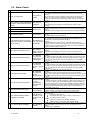
Text Messages .......................................................................................................................................................50
5.4
Restarting the NAUTICAST™ ..................................................................................................................................50
6
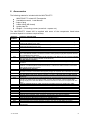
ACCESSORIES.................................................................................................................................................................51
7
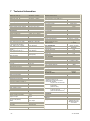
TECHNICAL INFORMATION ............................................................................................................................................52
7.1
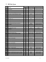
ERI Ship Types ........................................................................................................................................................53
8
CONTACT AND SUPPORT INFORMATION .....................................................................................................................54
9
APPENDIX ........................................................................................................................................................................55
9.1
Samples for battery calculation ................................................................................................................................55
9.1.1
Typical Installation ..........................................................................................................................................55
9.1.2
RM GMDSS Compact-Console Area A3 with 250 W MF/HF...........................................................................56
9.1.3
RM GMDSS Compact-Console Area A3 with 400 W MF/HF...........................................................................56
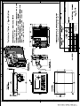
9.2
Drawings and Approvals ..........................................................................................................................................57
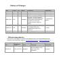
History of Changes
Date
2005-11-01
2006-07-14
2006-10-11
Version
1.0.0
1.0.1
1.0.2
Rev.
A
B
C
Status
Released
Released
Released
2008-12-05
1.0.5
D
Released
2008-12-05
1.0.6
E
Released
2009-09-15
1.0.8
F
Released
2009-09-27
2010-05-11
1.0.8
1.0.8
G
H
Released
Released
Comments
Editorial work
Character Change-out Edits
Update according to VTT&T,
Blue Sign, Factory Password
handling, removed reference to
specific default password and
noted this is now on the
protective cover on the unit
display.
Changes to drawings in appendix
Screen display updates due to
the changes during the
certification process ITU-R
M.1371-3
Software dependencies
Blue Sign Cable clarifications
Responsible
A. Lesch
M. D‟Arcangelo
M.D‟Arcangelo
C. Kabinger, B.
Werner
A. Lesch
A. Lesch
B.Werner
B. Werner
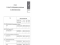
Software dependencies
This revision of the Manual is valid for the Software version (s) below stated and future
versions unless otherwise noted (ref.: www.acrelectronics.com / www.acr-europe.com ).
Date
AIS software
Version
Status
Comments
Responsible
2009-07-21
2.0.S116.X714
Released
New GPS Module. New
way to store ship
dimensions
A. Lesch
1 General Introduction
1.1 Description of AIS
What does the abbreviation AIS stand for?
AIS stands for: “Automatic Identification System”
What is AIS?
According to IALA regulations, AIS is defined as follows:
Very simply, the AIS is a broadcast Transponder system, operating in the VHF maritime
mobile Band. It is capable of sending ship information such as identification, position
course, speed and more, to other ships and to shore. It can handle multiple reports at
rapid update rates and uses Self-Organizing Time Division Multiple Access (SOTDMA)
technology to meet these high broadcast rates and ensure reliable and robust ship to ship
operation.
What are the performance standards of AIS?
The IMO defines the performance standards as follows:
-
Ship to Ship working
Ship to Shore working, including Long Range Application
Automatic and continuous operation
Provision of information messaging
Utilization of maritime VHF channels
Which modules make up an AIS-Transponder?
The Modules:
-
DGPS / GPS receiver
VHF Radio
Antenna
Computer (CPU)
Power Supply
Appropriate application software connects the individual modules.
In which modes does AIS function?
AIS are required to function flawlessly in a variety of modes. The relevant regulations require:
The system shall be capable of
- An "autonomous and continuous" mode for operation in all areas. This mode
shall be capable of being switched to/from one of the following alternate modes by
a competent authority;
- An "assigned" mode for operation in an area subject to a competent authority
responsible for traffic monitoring such that the data transmission interval and/or
time slots may be set remotely by that authority;
- A "polling or controlled" mode, where the data transfer occurs in response to
interrogation from a ship or competent authority.
Y1-03-0212H
1
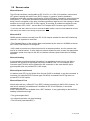
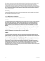
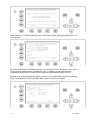
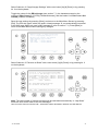
1.2 AIS in an Operational Environment
This illustration depicts a typical AIS System, where two or more AIS
equipped vessels (and shore based systems) are automatically
communicating with each other.
On the bottom, a typical NAUTICAST™ installation in a common environment is shown.
The NAUTICAST™ is connected to the vessels emergency power supply, and in
connection with the VHF, and GPS-Antennas, the minimal requirements for Transponder
operation are fulfilled.
Both vessels in the above illustration are equipped with a NAUTICAST™ (or any other
certified AIS-Transponder). Due to “Time – Synchronization” they use the same
organization of free and allocated windows (Slots) in the shared VHF Data Link (this
method is called “Self Organized Time Division Multiple Access”) to send and receive
messages.
Without the necessity of any active interaction, both vessels know exactly who or what is
cruising nearby and where the individual object is heading.
2
Y1-03-0212H
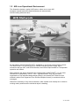
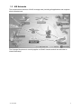
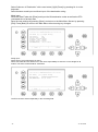
1.3 AIS Networks
The scenario below shows a full AIS coverage area (including all applications and complete
shore infrastructure).
The Carriage Requirement currently applies to SOLAS Vessels and will be extended on
Inland Waterways.
Y1-03-0212H
3
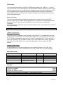
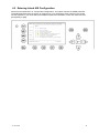
2 NAUTICAST
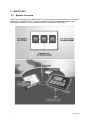
2.1 System Overview
Unlike other AIS devices, the NAUTICAST™ combines all required functions into one cabinet.
Additionally, the NAUTICAST™ gives the operator a number of additional features (easy
mounting & installation, environmental protection and smallest dimensions).
4
Y1-03-0212H
3 Installation
IMPORTANT: AUTHORITIES MANDATE that after the physical installation has
been successfully completed, all ships data and settings be entered into the AIS
transponder. See Section 4 for further instructions.
3.1 Installation Requirements
General Requirements
Please note that international conventions, regulations, instructions and guidelines have to be
adhered to when installing the NAUTICAST™.
The following points must be observed before installation can commence:
-
Permission by the local authority to install such a device must be granted.
Trained service personnel must undertake the installation.
The NAUTICAST™ must be fitted in a suitable place on the bridge.
The VHF and GPS Antennas must be installed in a suitable position, where excellent
reception conditions apply (refer to Chapter 3.10 Installation of VHF antenna)
All available interfaces must be installed.
The vessels power supply must suffice, and the GMDSS power supply has to be
used.
Installation of the pilot plug in conning position (close to the pilot working place).
3.2 Installation Overview
Survey
AIS is considered part of the ship‟s radio station and is surveyed together with radio
installation. Surveys on SOLAS Convention ships should be carried out in accordance with
the rules laid down in IMO Res. A 746(18) "Survey Guidelines under the harmonized system
of survey and certification" (R) 8, and "Protocol of 1988 relating to the International
Convention for the Safety of Life at Sea, 1974."
The NAUTICAST™ consists of one unit, which integrates all necessary modules.
Y1-03-0212H
5
Step-by-Step Installation Procedure:
Mount the NAUTICAST™ close to ships operation workstation for traffic surveillance
and maneuvering.
Use the VHF adapter cable (P/N 2612) together with the VHF plug and TNC plug to
connect the VHF and GPS antenna cables and antennas.
The sensors, ECDIS, PC, pilot case, long range devices and auxiliary displays can be
connected to the NAUTICAST™ cabinet by the AIS cable by means of the connection
box. The device is driven by a 24V DC 7A supply, which is connected to the power
terminal at the connection box. The AIS should be connected to an emergency power
source. A battery capacity calculation together with GMDSS-equipment is needed!
Please refer to Appendix 9.1 for examples of battery capacity calculations.
After performing these steps, the NAUTICAST™ automatically starts operation.
The NAUTICAST™ has a ground terminal which has to be connected to ship ground.
Now configure the required initial system parameters according to Chapter 4 “Starting
the NAUTICAST™.”
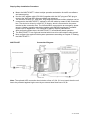
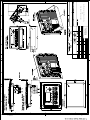
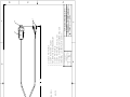
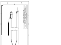
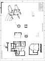
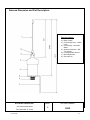
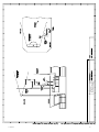
NAUTICAST
Connection Diagram
Note: The optional ACR connection box includes a fuse of 6,3A. If it is not used, then the unit
has to be protected against high current by an external slow blow fuse of 6,3A.
6
Y1-03-0212H
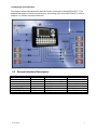
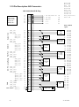
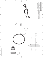
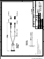
Components and Interfaces
The diagram below illustrates which devices can be connected to the NAUTICAST™. For a
detailed description of sensor connecting e.g. an existing Gyro to the NAUTICAST™ refer to
Chapter 3.5 “Sensor Interface Definitions.”
3.3 General Interface Description
Interface
Sensor 1
Sensor 2
Sensor 3
ECDIS
PILOT
LONG RANGE
DGPS (RTCM SC104)
ALARM CIRCUIT
Y1-03-0212H
Designation
CH 1
CH 2
CH 3
CH 4
CH 5 / CH 15
CH 8
CH 9
CH 10
Speed
Direction
4800bps or 38400bps
Input
4800bps or 38400bps
Input
4800bps or 38400bps
Input
38400bps
Input/Output
38400bps
Input/Output
38400bps
Input/Output
9600bps
Input/Output
Dry relay contact (power off and alarm state closed)
7
3.4 Interface NMEA Description:
3.4.1
Sensor - Interface CH1, CH2, CH3
Refer to Chapter 3.8 for detailed information on Sensor - Interface and Configuration.
3.4.2
ECDIS – Presentation Interface CH 4
Sentence Formatters
ABK UAIS Addressed and binary broadcast acknowledgement
ACA AIS Channel assignment message
ACK Acknowledge Alarm
AIR
UAIS Interrogation Request
ALR
Set Alarm State
ABM UAIS Addressed binary and safety related message
BBM UAIS Broadcast Binary Message
DSC Digital Selective Calling Information
DSE
Expanded Digital Selective Calling
DSI
DSC Transponder Initialize
DSR DSC Transponder Response
LRI
UAIS Long-Range Interrogation
LRF
UAIS Long-Range Function
SSD
Station Static Data
TXT
Text Transmission
VSD
Voyage Static Data
VDM UAIS VHF Data-link Message
VDO UAIS VHF Data-link Own-vessel report
8
Direction
out
in / out
in
in
out
in
in
out
out
out
out
out
out
in
out
in
out
out
Used Fields
All fields are provided
for Input and Output.
For further information
please refer to
IEC 61993-2 / NMEA
0183 HS V3.0 for
detailed field
information.
Y1-03-0212H
3.4.3
Pilot Port CH 5
The used sentence formatters for the pilot plug are the same as those listed for the ECDIS
port.
Note: A pilot input/output port is part of an AIS Class A installation. A plug connected to this
port should be installed on the bridge near the pilot‟s operating position, so that a pilot can
connect a Personal Pilot Unit (PPU) if required. Also, a power connector for the pilot unit
should be available nearby.
The pilot plug should be configured as follows: (Refer to SUB-COMMITTEE ON SAFETY OF
NAVIGATION NAV48/18 2.4.2002)
AMP/Receptacle (Square Flanged (-1) or Free-Hanging (-2)), Shell size 11, 9-pin,
Std. Sex 206486-1/2 or equivalent with the following connections:
- Tx A (out-) is connected to Pin 1
- Tx B (out+) is connected to Pin 4
- Rx A (in-) is connected to Pin 5
- Rx B (in+) is connected to Pin 6
- Shield is connected to Pin 9
3.4.4
Long Range CH 8
The AIS long range function requires a compatible long range communication system (e.g.
Inmarsat-C or MF/HF radio as part of GMDSS). This connection is required in order to
activate the long range function of the AIS. Its input/output port must meet the IEC 61162-2
requirements.
Sentence Formatters
LRI UAIS Long Range Interrogation
LRF UAIS Long-Range Function
LR1 UAIS Long-Range Reply Sentence l
LR2 UAIS Long-Range Reply Sentence 2
LR3 UAIS Long-Range Reply Sentence 3
Direction
Input
Input / Output
Output
Output
Output
Field Information:
All fields are provided for input and output.
For further information please refer to
IEC 61993-2 / NMEA 0183 HS V3.0 for detailed field
information.
Y1-03-0212H
9
3.4.5
DGPS – DGNSS Channel 9
Field / Protocol information:
All fields are provided with further information; please refer to ITU-R M.823-2 / RTCM SC 104
for detailed field information.
3.4.6
Alarm Circuit – BIIT Channel 10
The AIS requires that an alarm output (relay) must be connected to an audible alarm device
or the ships alarm system, if available.
Alternatively, the BIIT (built-in integrity test) alarm system may use the alarm messages
output on the presentation port (ECDIS Port Channel 5), provided the ECDIS alarm system is
connected and AIS compatible.
3.4.7
Proprietary Sentences
The proprietary ACR NMEA sentences have the NMEA registered manufacture talker ID
“NAU”. The $PNAU sentences are an addition to the standard sentences and offer other
manufactures full remote control to the Transponder. The additional “Extended NMEA
command set” – manual, which could be requested on demand, includes the full description
of how to use the proprietary NAUTICAST sentences.
Proprietary NMEA-Sentences $PNAU
MID - Mobile (MMS) Id
ASD - Advanced Ship Data
RCS - Read Configuration Settings
STO - Set Transponder Options
TSI
- Transponder State Information
SCR - Sensor Configuration Request
SCA - Sensor Configuration Acknowledge
SCD - Sensor Configuration Data
SCM - Sensor Configuration Mode
AIQ - Request status information from the Transponder
IVD – Inland AIS voyage data
SPW- Inland AIS security password sentence
SPR- Inland AIS security password response
10
Y1-03-0212H
3.5 Sensor Interface Definitions
All interface ports of the NAUTICAST comply with IEC-61162-1 / -2 and NMEA-0183 HS 3.0
specifications (aligned to RS422 parameters).
3.5.1
Talker drive circuits
The maximum output current is Imax = 50mA on each port. The drive circuit meets the
requirements of ITU-T V.11.
3.5.2
Listener Receiver Circuits
Multiple listeners may be connected to a single talker. Optional termination resistors
(120Ohm) for the input lines are provided in the connection box. The input terminals A, B and
C are electrically isolated from the remaining electronics of the listening device.
The input impedance is 30kOhm between A and B lines, disregarding the connection of
termination resistors. The minimum input voltage is ±0,3V.
The listener's receiver circuit complies with ITU-T V.11.
3.5.3
Electrical isolation
There are no direct electrical connections between the signal lines A and B.
The signal ground C must not be connected to the ship main ground or power line!
This isolation is in accordance with IEC 60945.
3.5.4
Maximum voltage on the bus
The maximum applied voltage between signal lines A and B and between either line and
ground C is in accordance with ITU-T V.11. For protection against incorrect wiring and for
unintended connection to older TALKER models, all receiver circuit devices are capable of
withstanding 15 V between both lines and signal ground for an indefinite period.
3.5.5
Data transmission
Data is transmitted in serial asynchronous form in accordance with IEC 61162-1. The first bit
is a start bit, and is followed by data bits, whereby the least significant bit is first.
The following parameters are used:
– Baud rate 38 400 (bits/s) 9600 (bits/s) 4 800 (bits/s)
– Data bits 8 (D7 = 0), parity none
– Stop bits 1.
Y1-03-0212H
11
3.6 Sensor notes
External Sensor
The AIS has interfaces (configurable as IEC 61162-1 or 61162-2) for position, bottom track
(BT) speed, heading and rate of turn (ROT) sensors. In general, sensors installed in
compliance with other carriage requirements of SOLAS Chapter V should be connected to the
AIS System.*1. The sensor information transmitted by AIS should be the same information
being used for navigation of the ship. Interfacing problems might occur if the existing on board
sensors do not have serial (IEC 61162) outputs. A converter is needed to translate the non
conform data to IEC 61162 – sensor data. For Example ACR Converter type P/N 2641.
*1) The fact that AIS is fitted on board a vessel does NOT entail the need to install additional sensors
other than those stated in the carriage requirements.
External GPS
GNSS position sensors normally have IEC 61162 outputs suitable for direct AIS interfacing.
However, it is important to note that:
• The Geodetic Datum of the position data is transmitted by the sensor in WGS84 so that an
IEC 61162 DTM sentence is configured.
• AIS is able to process two reference points for its antenna position, one for external, and
one for an internal sensor. If more than one external reference point is used, the appropriate
information needs to be input to the AIS, so that the reference point information is suitably
adjusted.
External Heading
A gyrocompass providing heading information is a mandatory sensor input to the AIS. A
converter unit (synchro or step-signal converter to NMEA 0183 v.3.0 for example ACR
Converter type P/N 2641 will be needed for AIS connection in the case that the ship‟s
gyrocompass does not provide IEC 61162 output.
External Speed and Course
If a bottom track (BT) log for Speed Over Ground (SOG) is available, it may be connected. A
converter (for example ACR Converter type P/N 2641) is needed if the BT-log does not
provide IEC 61162 outputs.
External Rate of Turn
Not all ships will carry a Rate-Of-Turn (ROT) indicator according to IMO A.526. However, if a
rate-of-turn indicator is available and it includes an IEC 61162 interface, it should be
connected to the AIS.
If ROT information is not available from a ROT indicator, it may (optionally) be derived from
heading information through:
• The gyrocompass itself,
• An external converter unit (see Heading),
• The AIS itself (calculated ROT).
12
Y1-03-0212H
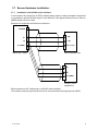
3.7 Sensor Hardware Installation:
3.7.1
Installation of an RS422 serial interface:
In most cases, the output from a GPS is already being used by existing navigation equipment.
It is possible to split an RS 422 output for two devices. If the signal becomes too low, then an
NMEA splitter has to be used.
Example for single talk multi-listener connection:
Shields
A
- IN
B
+ IN
C (GND)
Talker (e.g.: GPS)
G1 (or 2,3)
AIS Conncetion Box
A
B
C (GND)
Listener (other
equipment)
Each interface on the Transponder is a RS422 serial interface
The shield or ship main ground should not be connected with the signal ground (GND).
Y1-03-0212H
13
3.8 Sensor Software Configuration
3.8.1
Introduction
The NAUTICAST™ AIS requires a connection to various sensor devices. Sensor
Configuration should enable compatibility with existing navigation devises aboard any vessel.
This chapter deals with several ways to configure the NAUTICAST™ and to comply with the
requirements of the specific sensor interfaces.
Configuration and display is visible on two screens of the Sensor Configuration Menu. The
NAUTICAST™ offers the following configuration options:
Set up data speed 4800/9600/38400 baud.
Monitor the connected sensor inputs for each sensor channel.
Verify and edit the Sensor Configuration on the display screen.
Analyze the information received from the connected sensor devices.
Produce an electronic installation report.
Configuration of various NMEA protocols.
The individual options may be repeated until the required configuration for the connected
sensor devices is achieved.
During the configuration process, the NAUTICAST™ is not operational.
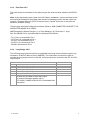
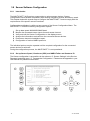
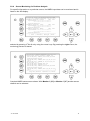
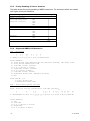
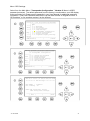
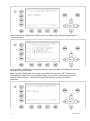
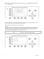
3.8.2
Set up Sensor Speed, Checksum (CRC) and NMEA Talker and Sentence ID
The Sensor configuration is accessible via the submenu „5. Sensor Settings‟ in the Service
Password protected menu: „5. Transponder Configuration‟. Please see the appendix in your
User Manual for password information.
N48^12' E 16^26' |1>0.00|2>0.00|3>0.00nm
|---------------------------------| 5. Transponder Configuration
-----| |
| +- 1. Change User Password
View | +- 2. Region Settings
| +- 3. Alarm Settings
-----| +- 4. Interrogation Settings
| +- 5. Sensor Settings
Msg. | +- 6. GPS Settings
| +- 7. Inland AIS Configuration
-----|
|
Displ|
---------------------------------------NUM|Select->|
|
|<-Back
14
Y1-03-0212H
After accessing the Sensor Configuration menu this main configuration screen is active:
N 1o19' E 0o12' |1> N/A|2>0.00|3>0.10nm
*********** Sensor Settings ************
BaudRate Sensor1:< 4800>
CRC: auto
Ignored:$HC---$-----$-----$----$-----$-----$-----$----1>Start Monitor>
BaudRate Sensor2: 4800
CRC: auto
Ignored:$HC---$-----$-----$----$-----$-----$-----$----2>Start Monitor>
BaudRate Sensor3: 38400
CRC: auto
Ignored:$HC---$-----$-----$----$-----$-----$-----$----3>Start Monitor>
---------------------------------------| Save | Default | Analyze | Back
A variety of possible settings can be made on this screen. It is possible to navigate from one
configuration item to another by pressing the up and down arrow keys. Value will be changed
by pressing the left and right arrow key. The fastest way to jump from one sensor to another
is by pressing numbers 1 – 3 on the keyboard. (Refer also to chapter 3.8.4 for specific
information on a particular sensor)
The following changes can be undertaken for each of the sensor interfaces (by left and right
arrow key):
o
Changing the baud rate (4800, 9600 and 38400) to the required speed of the sensor
device by pressing the right or left arrow keys.
o
Enabling or disabling CRC-Checking by pressing the right or left arrow keys.
<auto>
Sentence will be accepted with or without Checksum
<on>
Checksum must be available
o
Configuring NMEA sentences, which the system filters and ignores
There are 5 entry fields where characters can be input. Two positions of each entry
field are for Talker-Id, and three for Sentence-Id, which represents the NMEAsentence which should be ignored by the system.
(i.e. the default setting: “HC“ means ignore all NMEA records starting with HC on this
particular sensor interface)
Note: HC stands for magnetic north and should be ignored.
For Example:
--VTG means all VTG sentence IDs will be ignored like GPVTG, GNVTG…
VW--- means all VW Talkers ID from speed log will be ignored like VWVHW, VWVBW
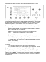
Changes on this screen can be saved by pressing the “Save” – Button [M5].
The factory settings can be recalled be pressing the “Default” – Button [M6].
Returning back to the previous screen is possible by pressing the “BACK” – Button [M8].
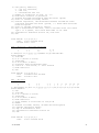
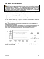
The next step is the analysis of the current sensor interface settings, which can be
undertaken with the “Analyze” – Button [M7]. After pressing this button, the real-time analysis
of the sensor data stream begins. This process takes around 30 seconds and is visible on a
temporary screen.
Y1-03-0212H
15
*********** Sensor Settings ************
**************************************
*
*
* Please stay...
*
*
analyze Sensor 1..3
*
*
this takes max. 30sec.
*
*
*
**************************************
---------------------------------------|
|
|
| Back
It is possible to interrupt this process by pressing the “Back” - Button [M8].
After the analysis is complete, the Transponder will list the data used for the AIS operation.
N 1o18' E 0o12' |1> N/A|2>0.00|3>0.10nm
************ Sensor Analyze ************
Analyze:
Date
Src
Used
CHx
Update
Position: Ext >$GPGLL 1,2
820ms
: Int
$GPGGA i,1
273ms
: Int
$GPRMC i,1,3
656ms
UTC
: Ext
$GPGLL 1,2
820ms
: Int
$GPGGA i,1
273ms
: Int
$GPRMC i,1,3
656ms
Date
: Int
$GPRMC i,1,3
656ms
COG
: Ext
$GPVTG 1,2
792ms
: Int
$GPRMC i,1,3
656ms
SOG
: Ext
$VDVBW 1,2
820ms>
---------------------------------------| Select |
|
| Back
16
Y1-03-0212H
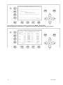
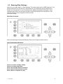
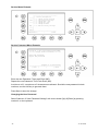
3.8.3
Real-Time Analysis of NMEA Data Streams
After these configuration procedures, an overview of the current Sensor Software
Configuration has been attained.
This filtered NMEA data can be analyzed further. The data source is shown on the screen
below. The source can be internal or external devices, the received NMEA sentence and the
channel where this data was identified (Sensor 1, 2, 3 or calculated), as well as the measured
update rate.
N 1o19' E 0o13' |1> N/A|2>0.00|3>0.10nm
************ Sensor Analyze ************
Analyze:
Date
Src
Used
CHx
Update
Position: Ext
$GPGLL 1,2,3
898ms
: Int
$GPGGA i,1,3
291ms
: Int
$GPRMC i,1,3
812ms
UTC
: Ext
$GPGLL 1,2,3
898ms
: Int
$GPGGA i,1,3
291ms
: Int
$GPRMC i,1,3
812ms
Date
: Int
$GPRMC i,1,3
812ms
COG
: Ext
$GPVTG 1,2,3
898ms
: Int
$GPRMC i,1,3
812ms
SOG
: Ext >$VDVBW 1,2,3
934ms>
---------------------------------------| Select |
|
| Back
To view any NMEA sentence in detail, the required data line can be selected by pressing
[Enter]. The detailed information on this source appears as follows:
N 1o19' E 0o13' |1> N/A|2>0.00|3>0.10nm
********* Details on Sentence **********
$VDVBW ext. on <Ch1> :SOG
Sentence
: VBW
Update Rate: 1093ms
Used Fields: 4,5,6
4:LonGS 5:TraGS
6:Data Valid
Talker : VD
ChkSum : Ok
[09:21:53,062] $VDVBW,19.63,-01.32,V,19.
63,-01.33,A*47
[09:21:51,859] $VDVBW,19.63,-01.31,V,19.
63,-01.33,A*44
---------------------------------------|
| Next
|
| Back
It is possible to scroll through the sources of this sensor interface channel by pressing the
“Next” –Button [M6]. The previous menu can be accessed at any time by pressing the “Back”
– Button [M8].
Y1-03-0212H
17
Each time the analysis process for sensor configuration is undertaken; a trace file (see below)
is automatically generated and sent out to the ECDIS-Port. This output can also be used as a
Sensor Configuration Report.
$PNAUSCA,4800,4800,4800,1
$PNAUSCD,------------ Sensor Settings -----------$PNAUSCD,Date
: 06/22/2004 08:57:05
$PNAUSCD,Hardware: AIS Transponder Class A
$PNAUSCD,Software: 2.0.0.11R3
$PNAUSCD,SW Stamp: Jun 14 2004 11:46:10
$PNAUSCD,LAT
: N 53o30.123' LON : E 10o 1.234'
$PNAUSCD,Heading : ExtHDT:0o
iRot : 0o/min
$PNAUSCD,IMO No. : 303174162
MMSI: 2222222
$PNAUSCD,ShipName: U4 CS : D11233
$PNAUSCD,ShipType: Pilot vessel
$PNAUSCD,Length : 220m Beam: 43m
$PNAUSCD,RefPtExt: A200 B20 C10 D33m
$PNAUSCD,RefPtInt: A190 B30 C20 D23m
$PNAUSCD,Cargo
: N/A or harmless
$PNAUSCD,Draught : 24.8m
$PNAUSCD,Dest.
: CASABLANCA
$PNAUSCD,ETA
: 10/13 12:31
$PNAUSCD,NavStat : Engaged in fishing
$PNAUSCD,EPFDType: GPS
$PNAUSCD,------------ Sensor Settings -----------$PNAUSCD,BaudRate Sensor1: 4800
CRC:auto
$PNAUSCD,Ignored:$-----$-----$-----$----$PNAUSCD,
:$-----$-----$-----$----$PNAUSCD,BaudRate Sensor2: 4800
CRC:auto
$PNAUSCD,Ignored:$HC---$-----$-----$----$PNAUSCD,
:$-----$-----$-----$----$PNAUSCD,BaudRate Sensor3: 4800
CRC:auto
$PNAUSCD,Ignored:$HC---$-----$-----$----$PNAUSCD,
:$-----$-----$-----$----$PNAUSCD,------------ Sensor Settings -----------$PNAUSCD,Analyze:
$PNAUSCD,Date
Src
Used
CHx
Update
$PNAUSCD,Position: Ext
$GPGLL 1
955ms
$PNAUSCD,UTC
: Int
$GPGGA i
952ms
$PNAUSCD,Date
: Int
$GPRMC i
951ms
$PNAUSCD,COG
: Ext
$VDVBW 1 Calc
952ms
$PNAUSCD,SOG
: Ext
$VDVBW 1 Calc
952ms
$PNAUSCD,Heading : Ext
$TIHDT 1
953ms
$PNAUSCD,ROT
: Ext
$TIROT 1
949ms
$PNAUSCD,------------ Sensor Settings -----------$PNAUSCD,Monitoring Sensor Channel 1
$PNAUSCD,[08:56:35,000] $TIROT,0.0,A
$PNAUSCD,[08:56:35,255] $GPGLL,5330.1234,N,01001
$PNAUSCD,.2345,E,141800.00,A,A
$PNAUSCD,[08:56:35,410] $GPVTG,350.0,T,,M,10.0,N
...
...
$PNAUSCD,[08:49:50,806] $TIHDT,359.9,T
$PNAUSCD,------------ ROT
: -----------------$PNAUSCD,$TIROT ext. on Ch1 :ROT
$PNAUSCD,
$PNAUSCD,Sentence
: ROT
Talker : TI
$PNAUSCD,Update Rate: 949ms ChkSum : N/A
$PNAUSCD,Used Fields: 1,2
$PNAUSCD, 1:Rate Of Turn
$PNAUSCD, 2:Data Valid
$PNAUSCD,
$PNAUSCD,[08:49:52,900] $TIROT,0.0,A
$PNAUSCD,[08:49:51,950] $TIROT,0.0,A
$PNAUSCD,[08:49:51,001] $TIROT,0.0,A
$PNAUSCD,
$PNAUSCD,------------ Sensor Settings ------------
18
Y1-03-0212H
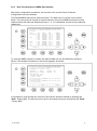
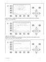
3.8.4
Sensor Monitoring for Problem Analysis
For specific information on a particular sensor, the NMEA input data can be monitored and is
listed on the AIS display.
N 1o21' E 0o15' |1> N/A|2>0.00|3>0.10nm
*********** Sensor Settings ************
BaudRate Sensor1:< 4800>
CRC: auto
Ignored:$HC---$-----$-----$----$-----$-----$-----$----1>Start Monitor>
BaudRate Sensor2: 4800
CRC: auto
Ignored:$HC---$-----$-----$----$-----$-----$-----$----2>Start Monitor>
BaudRate Sensor3: 38400
CRC: auto
Ignored:$HC---$-----$-----$----$-----$-----$-----$----3>Start Monitor>
---------------------------------------| Save | Default | Analyze | Back
From the Sensor Configuration main screen one of the three sensor channels may be
selected by pressing 1, 2 or 3 or by using the cursor keys. By pressing the right cursor, the
monitoring process is started.
*********** Sensor Settings ************
Monitoring Sensor Channel 2 PAGE 1/4
[08:26:48,000] $GPGLL,5330.1234,N,01001
.2345,E,141800.00,A,A
[08:26:48,328] $GPVTG,350.0,T,,M,10.0,N
,,K,A
[08:26:48,437] $VDVBW,11.00,01.00,A,12.
00,02.00,A,,V,,V
[08:26:48,547] $TIHDT,359.9,T
[08:26:48,656] $TIROT,0.0,A
[08:26:48,765] $GPGLL,5330.1234,N,01001
.2345,E,141800.00,A,A
[08:26:48,875] $GPVTG,350.0,T,,M,10.0,N
,,K,A
>
---------------------------------------|Cfg CH2 |Monitor 1|Monitor 3|<-Back
Complete NMEA sentence are shown. With Monitor 2 [M6] or Monitor 3 [M7] another sensor
channel can be selected.
Y1-03-0212H
19
3.8.5
Priority Handling of Sensor Sentence
This table shows the priority handling of NMEA sentences. The sentences which are treated
with higher priority are listed first.
Positioning System
Time of Position
Latitude/Longitude
Position accuracy
Rate of Turn(ROT)
Reference Datum
Speed over Ground
Heading
RAIM Indicator
Source
Priority
HIGH
GNS
GLL
GGA
RMC
ROT
DTM
VBW
VTG
OSD
RMC
HDT
OSD
GBS
LOW
3.8.6
Supported NMEA-0183 Sentences
DTM - Reference
1
2 3
4 5
6 7
8
9
|
| |
| |
| |
|
|
$--DTM,ccc,a,x.x,a,x.x,a,x.x,ccc*hh<CR><LF>
Field Numbers:
1) Local datum code (W84,W72,S85,P90,999-user defined, IHO datum code)
2) Local datum subdivision code
3) latitude offset, minutes
4) N or S (North or South)
5) longitude offset, minutes
6) E or W (East or West)
7) altitude offset, meters
8) Reference datum code ((W84,W72,S85,P90)
9) CRC
Used Fields: 1,8
1: Local datum code
8: Reference datum code
GGA - Positioning System Fix Data
Time, Position and fix related data form GPS receiver.
11
1
2
3 4
5 6 7 8
9 10 | 12 13 14
15
|
|
| |
| | | |
|
| |
| |
|
|
$--GGA,hhmmss.ss,llll.ll,a,yyyyy.yy,a,x,xx,x.x,x.x,M,x.x,M,x.x,xxxx*hh
Field Numbers:
1) UTC
2) Latitude
3) N or S (North or South)
4) Longitude
5) E or W (East or West)
20
Y1-03-0212H
6) GPS Quality Indicator,
0 - fix not available,
1 - GPS fix,
2 - Differential GPS fix
7) Number of satellites in view, 00 - 12
8) Horizontal Dilution of precision
9) Antenna Altitude above/below mean-sea-level (geoid)
10) Units of antenna altitude, meters
11) Geoidal separation, the difference between the WGS-84 earth
ellipsoid and mean-sea-level (geoid), \-\ means mean-sea-level
below ellipsoid
12) Units of geoidal separation, meters
13) Age of differential GPS data, time in seconds since last SC104
type 1 or 9 update, null field when DGPS is not used
14) Differential reference station ID, 0000-1023
15) CRC
Used Fields: 1,2,3,4,5,6,7
1:UTC
2:Lat 3:LaInd 4:Lon
5:LoInd 6:Acc 7:Sat
GLL - Position - Latitude/Longitude
1
2 3
4 5
6 7 8
|
| |
| |
| | |
$--GLL,llll.ll,a,yyyyy.yy,a,hhmmss.ss,A,a*hh<CR><LF>
Field Numbers:
1) Latitude
2) N or S (North or South)
3) Longitude
4) E or W (East or West)
5) Universal Time Coordinated (UTC)
6) Status A - Data Valid, V - Data Invalid
7) Mode indicator
8) CRC
Used Fields: 1,2,3,4,5,6,7
1:Lat
2:LaInd 3:Lon 4:LoInd
5:UTC
6:Valid 7:Acc
GNS - Fix Data
1
2
3 4
5 6
7 8
9
10 11 12 13
|
|
| |
| |
| |
|
|
|
|
|
$--GNS,hhmmss.ss,llll.ll,a,yyyyy.yy,a,c--c,xx,x.x,x.x,x.x,x.x,x.x*hh
Field Numbers:
1) UTC
2) Latitude
3) N or S (North or South)
4) Longitude
5) E or W (East or West)
6) Mode indicator
7) Total number of satellites in use,00-99
8) HDROP
9) Antenna altitude, meters, re:mean-sea-level(geoid)
10) Goeidal separation meters
11) Age of differential data
12) Differential reference station ID
13) CRC
Used Fields: 1,2,3,4,5,6,7
1:UTC
2:Lat 3:LaInd 4:Lon
Y1-03-0212H
21
5:LoInd 6:Acc 7:Sat
RMC - Minimum Navigation Information
12
1
2 3
4 5
6 7
8
9
10 11| 13
|
| |
| |
| |
|
|
|
| | |
$--RMC,hhmmss.ss,A,llll.ll,a,yyyyy.yy,a,x.x,x.x,ddmmyy,x.x,a,a*hh<CR><LF>
Field Numbers:
1) UTC Time
2) Status, V = Navigation receiver warning
3) Latitude
4) N or S
5) Longitude
6) E or W
7) Speed over ground, knots
8) Course over Ground, degrees true
9) Date, ddmmyy
10) Magnetic Variation, degrees
11) E or W
12) Mode Indicator
13) CRC
Used Fields: 1,2,3,4,5,6,7,8,9,10,11,12
1:UTC 2:Valid 3:Lat 4:LaInd 5:Lon
6:LoInd
7:SOG 8:COG
9:Date 10:MagV 11:MagIn 12:Acc
VBW - Ground/Water Speed
1
2
3 4
5
6 7
|
|
| |
|
| |
$--VBW,x.x,x.x,A,x.x,x.x,A*hh<CR><LF>
Field Numbers:
1) Longitudinal water speed, \-\ means astern
2) Transverse water speed, \-\ means port
3) Status, A = Data Valid
4) Longitudinal ground speed, \-\ means astern
5) Transverse ground speed, \-\ means port
6) Status, A = Data Valid
7) CRC
Used Fields: ,5,6
4:LonGS 5:TraGS 6:Valid
VTG - made good and Ground speed
1
2 3
4 5
6 7 8 9 10
|
| |
| |
| | | | |
$--VTG,x.x,T,x.x,M,x.x,N,x.x,K,A*hh<CR><LF>
Field Numbers:
1) Track Degrees
2) T = True
3) Track Degrees
4) M = Magnetic
5) Speed Knots
6) N = Knots
7) Speed Kilometres per Hour
8) K = Kilometres per Hour
9) Status, A = Data Valid
10)CRC
22
Y1-03-0212H
Used Fields: 1,5,6,7,8,9
1:COG 5:SOG 6:SOGIn 7:SOG 8:SOGIn 9:Valid
OSD - Ship Data
1
2 3
4 5
6 7
8
9 10
|
| |
| |
| |
|
| |
$--OSD,x.x,A,x.x,a,x.x,a,x.x,x.x,a*hh<CR><LF>
Field Numbers:
1) Heading, degrees true
2) Status, A = Data Valid
3) Vessel Course, degrees True
4) Course Reference
5) Vessel Speed
6) Speed Reference
7) Vessel Set, degrees True
8) Vessel drift (speed)
9) Speed Units
10) CRC
Used Fields: 1,2,3,4,5,6,9
1:HDT 2:HDTVal 3:COG
5:SOG 6:SOGRef 9:SOGInd
4:COGRef
HDT - True
1
2 3
|
| |
$--HDT,x.x,T*hh<CR><LF>
Field Numbers:
1) Heading Degrees, true
2) T = True
3) CRC
Used Fields: 1,2
1:HDT 2:HDTRu
ROT - Of Turn
1
2 3
|
| |
$--ROT,x.x,A*hh<CR><LF>
Field Numbers:
1) Rate Of Turn, degrees per minute, \-\ means bow turns to port
2) Status, A means data is valid
3) CRC
Used Fields: 1,2
1:ROT 2:Valid
Y1-03-0212H
23
3.8.7
Calculated Values
Processed dynamic ship data such as position, SOG etc. is generated by NMEA sentences.
Exceptions:
If "Calc" is displayed on the sensor analyze screen, this means that this sentence is used for
calculating dynamic ship data.
ROT out of HDT
ROT direction left / right -/+ will be calculated out of the HDT Message, if a TIROT sentence
(only “TI”-Talker devices are valid) is not connected.
ROT > +10°/min
ROT < -10°/min
Other
Output +720°/min
Output -720°/min
Output 0°/min
COG information out of VBW
COG will be generated out of VBW, if HDT is available. In this case the atan2 of the
longitudinal and transversal speed plus heading is basis of the calculation.
Longitudinal/Transversal SOG from VBW
If VBW is available, SOG is also calculated without HDT.
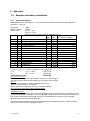
3.8.8
Versions of NMEA Sentences
RMC
v2.30 - $GPRMC,122500.00,A,5330.1234,N,01001.2345,E,11.2,352.2,120202,2.0,E,A
v2.20 - $GPRMC,122500.00,A,5330.1234,N,01001.2345,E,11.2,352.2,120202,2.0,E
GLL
v2.30 - $GPGLL,5330.1234,N,01001.2345,E,141800.00,A,A
v2.00 - $GPGLL,5330.1234,N,01001.2345,E,141800.00,A
v1.50 - $GPGLL,5330.1234,N,01001.2345,E
GGA
v2.00 - $GPGGA,092854,5330.1234,N,01001.2345,E,1,3,1.2,65.2,M,45.1,M,,
v1.50 - $GPGGA,092854,5330.1234,N,01001.2345,E,1,3,1.2,65.2,M,45.1,M
VBW
v2.30 - $VDVBW,11.00,01.00,A,12.00,02.00,A,,V,,V
v2.20 - $VDVBW,11.00,01.00,A,12.00,02.00,A
VTG
v2.30 - $GPVTG,350.0,T,,M,10.0,N,,K,A
v2.20 - $GPVTG,350.0,T,,M,10.0,N,,K
OSD
v2.30 - $INOSD,359.9,A,5.2,B,12.6,B,150.0,1.2,N
v2.20 - $INOSD,359.9,A,5.2,B,12.6,B,150.0
24
Y1-03-0212H
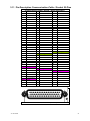
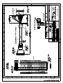
3.9 Pin-Description AIS-Cable / Socket 50-Pins:
TxA out –
TxB out +
RxA in –
RxB in +
AIS Cable/Socket ( Sub-D 50 Plug )
1
CH5_out+
18
2
CH5_out-
3
CH5_gnd
4
CH5_in-
6
CH6_Vin
7
8
9
CH4_gnd
21
CH4_in+
22
CH4_in-
23
CH8_in+
24
CH8_in-
25
CH8_gnd
26
CH8_in+
CH6_CANH
11
CH1_gnd
27
CH8_in-
28
Spare
29
CH3_in-
CH1_in+
13
CH2_in-
14
CH2_gnd
16
20
CH6_CANL
CH1_in-
15
CH4_out-
CH6_gnd
10
12
19
CH5_in+
5
30
CH3_gnd
31
CH3_in+
32
Vin_gnd
CH2_in+
Vin+ (24V)
33
34
Spare
35
Spare
36
Spare
37
Spare
38
Spare
39
CH9_gnd
40
CH9_out-
41
CH9_in-
42
CH9_in+
43
CH9_out+
44
Spare
45
Spare
46
CH10_1
47
CH10_2
48
Vin_gnd
49
Vin_gnd
50
Spare
Ch4_out+
Vin+ (24V)
17
Vin+ (24V)
CH1
Sensor
CH4
ext. Display
CH8
Long Range
CH2
Sensor
CH5
aux. Display
CH9
DGNSS
BIIT / Relay
CH3
Sensor
CH6
opt. 61162-3
CH10
(max. 30V DC / 1A)
Spare
Do not use
AIS Plug and Socket
Y1-03-0212H
25
Black BK
White WH
Red
RD
Green GN
Brown BR
Blue BL
Orange OR
Yellow YL
Violet VI
Gray SL(Slate)
Pink PK
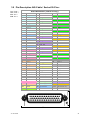
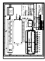
3.10 Pin-Description AIS-Connector:
AIS -Cable Sub-D 50 Plug
Note:
TxA out –
TxB out +
RxA in –
RxB in +
16
17
33
48
49
32
+ 24 VDC/max 5A
+ 24 VDC
+ 24 VDC
0 V
0 V
0 V
rd
rd
rd
bl
bl
bl
AIS-Cable
Open
CAN
DGPS
Long Range Pilot Port
ECDIS
Sensor 1,2,3
CH1_in+
CH1_inCH1_gnd
CH2_gnd
CH2_in+
CH2_inCH3_in+
CH3_inCH3_gnd
CH4_gnd
CH4_in+
CH4_inCH4_out+
CH4_outCH5_in+
CH5_inCH5_out+
CH5_outCH5_gnd
CH8_gnd
CH8_in+
CH8_inCH8_out+
CH8_outCH9_in+
CH9_inCH9_out+
CH9_outCH9_gnd
Spare_gnd
Spare_in+
Spare_inSpare_out+
Spare_outCH6_CANH
CH6_CANL
CH6_Vin
CH6_gnd
CH10_1
BIIT Relais CH10_2
26
12
10
11
14
15
13
31
29
30
20
21
22
18
19
4
5
1
2
3
25
26
27
23
24
42
41
43
40
39
36
35
34
38
37
9
8
6
7
46
47
SPEED
LOG
VBW
e.g. GPS
GLL, VTG,
DTM
e.g. GYRO
HDT,ROT
e.g ECDIS
viewer
6 AMP
5 Pilot
4 Plug
1
NC
e.g.
Inmarsat
unit
RTCM
SC104
NC unit
NC
NC
Service
unit
CAN
unit
Alarm unit
1
2
3
7
5
6
9
10
11
17
13
14
15
16
19
20
21
22
23
29
25
26
27
28
31
32
33
34
35
41
37
38
39
40
43
44
45
46
49
50
WH/BK
BR/BK
SL/GN
YL/SL
PK/GN
YL/PK
GN/BL
YL/BL
GN/RD
YL/RD
GN/BK
YL/BK
SL/BL
PK/BL
SL/RD
PK/RD
SL/BK
PK/BK
WH/SL
SL/BR
WH/PK
PK/BR
WH/BL
BR/BL
WH/YL
YL/BR
WH/GN
BR/GN
SL/PK
RD/BL
SL
PK
GN
YL
WH
BR
RD
BL
BK
VI
Y1-03-0212H
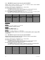
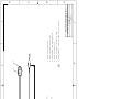
3.11 Pin-Description Communication-Cable / Socket 50-Pins
Communication-Cable / Socket ( Sub-D 50 Socket )
1
34
18
2
35
19
3
36
20
4
37
21
5
38
22
6
39
23
7
40
24
8
41
25
9
42
26
10
43
27
11
44
28
Blue Sign - Switch
Blue Sign - Switch
12
45
29
13
46
30
14
47
31
15
CH15_TxD
48
32
16
CH15_RxD
49
CH15_GND
33
17
50
CH15
Communication
RS232
Spare
Do not use
Communication Socket (female)
Y1-03-0212H
27
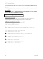
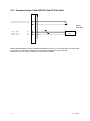
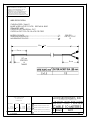
3.12 Communication Cable RS232 (Sub-D 50 Socket)
BlueSign Switch
BlueSign Switch
28
44
RS232
SUB-DB9
CH15_RxD
CH15_TxD
CH15_gnd
32
15
49
Communication
PC
3
2
5
Cable 2635 (NAU-B502) includes a RS232 SUB-DB9 connector for PC communication and flying leads
for connection to a Blue Sign Switch (user-provided and Single throw On/Off required.)
WARNING - DO NOT APPLY POWER TO THE SWITCH LEADS!
28
Y1-03-0212H
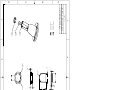
3.13 Installation of VHF / GPS Antennas
Interference to the Ship’s VHF Radiotelephone
The AIS ship borne equipment, like any other ship borne transceiver operating in the VHF
maritime band, may cause interference to a ship‟s VHF radiotelephone. Because AIS is a
digital system, this interference may occur as a periodic (e.g. every 20 seconds) soft clicking
sound on the ship‟s radiotelephone. This affect may become more noticeable if the VHF
radiotelephone antenna is located close to the AIS VHF antenna, and when the
radiotelephone is operating on channels near the AIS operating channels (e.g. channels 27,
28 and 86).
Attention should be paid to the location and installation of the various antennas, in order to
support the antenna characteristics in the best possible way.
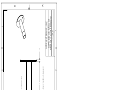
3.13.1 VHF Antenna Installation
Antenna Location
Location of the mandatory AIS VHF-antenna should be carefully considered. Digital
communication is more sensitive than analogue/voice communication to interference created
by reflections caused by obstructions such as masts and booms. It may be necessary to
relocate the VHF radiotelephone antenna to minimize interference effects.
To minimize the interference effects, the following guidelines apply:
The AIS VHF antenna should have omni directional vertical polarisation.
The AIS VHF antenna should be placed in an elevated position, as free standing as
possible, with a minimum of 2 meters in horizontal direction from constructions made
of conductive materials. The antenna should not be installed close to any large vertical
obstruction. The AIS VHF antenna should have a visible sky of 360°.
The AIS VHF antenna should be installed at least 3 meters away from interfering highpower energy sources such as radar and other transmitting radio antennas, and out of
the way of the transmitting beam.
There should not be more than one antenna on each level. The AIS VHF antenna
should be mounted directly above or below the ship‟s primary VHF radiotelephone
antenna, with no horizontal separation and a minimum of 2 meters vertical separation.
If it is located on the same level as other antennas, the distance apart should measure
at least 10 meters.
See also sample for antenna layout in the Appendix (Drawings and Approvals)
Cabling
The cable should be kept as short as possible to minimize attenuation of the signal. Double
shielded coaxial cables equal to or better than RG214 is recommended.
RG214 at VHF attenuation per meter of app. 0,07 dB/m (45m = 3,15db)
VHF AIS frequency app. 162MHz
Y1-03-0212H
29
All outdoor connectors on the coaxial cables should be fitted with preventive isolation, such
as shrink-stocking with silicone to protect the antenna cable against water penetration.
Coaxial cables should be installed in separate signal cable channels/tubes, and at least 10
cm away from any power supply cables. Crossing of cables should take place at right angles
(90°). Coaxial cables should not be exposed to sharp bends, which may lead to changes to
the characteristic impedance of the cable. The minimum bend radius should be 5 times the
cables outside diameter.
Grounding
Coaxial down-leads must be used for all receiving antennas, and the coaxial screen should
be connected to the ground at one end.
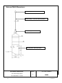
3.13.2 GNSS Antenna installation
A Class A AIS must be connected to a GNSS antenna.
Location
The GNSS antenna must be installed where it has a clear view of the sky, so that it accesses
the horizon freely through 360°, with a vertical observation of 5 to 90 degrees above the
horizon. Small diameter obstructions, such as masts and booms, do not seriously impair
signal reception, but such objects must not eclipse more than a few degrees of any given
bearing.
The antenna must be located at least three meters away from, and out of the transmitting
beam of high-power transmitters (S-Band Radar and/or Inmarsat systems). This includes the
ship‟s own AIS VHF antenna, if it is designed and installed separately. See also sample for
antenna layout in Installation Manual Appendix 8.2 (Drawings)
If a DGNSS system is included or connected to the AIS system, the installation of the antenna
should be undertaken in accordance with IEC 61108-4, Edition 1.
Cabling
To achieve optimum performance, the gain of the antenna pre-amplifier should match the
cable attenuation. The NAUTICAST can be equipped with two different types of internal GPS
receivers. It differs between „Jupiter‟ and „µBlox‟
The resulting installation gain for Jupiter (pre-amplifier gain - cable attenuation) should be
within 0 to 10 dB and for µBlox 5 to 15 dB. RG214 as GPS antenna cable has an attenuation
per meter of app. 0,35 dB/m (45m = 15,75dB); GPS frequency app. 1,2GHz).
The coaxial cable between the antenna and the AIS ship borne station connector should be
routed directly, in order to reduce electromagnetic interference. The cable should not be
installed close to high-power lines, such as radar or radio-transmitter lines, or near the AIS
VHF antenna cable. A space of one meter or more is recommended in order to avoid
degradation due to RF-coupling. Crossing of antenna cables should take place at 90 degrees,
to minimize magnetic field coupling.
30
Y1-03-0212H
Menu „GPS Settings:
Select from the Main Menu “Transponder Configuration ” Number 5. Menu is USER
password protected. The default password from the factory is mentioned on your AIS display
at the protection foil. Please see the appendix in your User Manual for additional password
information.. Enter User Password and use the up and down arrows on keypad to select “6.
GPS settings” or “by pressing number 6 on the keypad.
N 1o19' E 0o13' |1>0.01|2>1.30|3>1.80nm
|---------------------------------| Menu
-----| |
| +- 1. Messages
View | +- 2. AIS Status
| +- 3. Voyage Settings
-----| +- 4. Ship Settings
| +- 5. Transponder Configuration
Msg. | +- 6. Service Configuration
| +- 7. Display Settings
-----| +- 8. Graphical Display Settings
|
Displ|
---------------------------------------NUM|Select->|
|
|<-Back
N48^12' E 16^26' |1> N/A|2> N/A|3>0.00nm
|---------------------------------| 5. Transponder Configuration
-----| |
| +- 1. Change User Password
View | +- 2. Region Settings
| +- 3. Alarm Settings
-----| +- 4. Interrogation Settings
| +- 5. Sensor Settings
Msg. | +- 6. GPS Settings
|
-----|
|
Displ|
---------------------------------------NUM|Select->|
|
|<-Back
N48^12' E 16^26' |1> N/A|2> N/A|3>0.00nm
************* GPS Settings *************
GPS module : <Jupiter>
Pos. Pinning: On
NOTE: The system will restart
when saving these settings.
---------------------------------------| Save |
|
| Back
Y1-03-0212H
31
GPS module:
The screen provides means to switch the GPS Module between the „<µBlox>‟ or „<Jupiter>‟.
You can force the AIS to search again for the GPS Module installed. Selecting the wrong type
of GPS module may result in invalid position information and/or malfunction so that your AIS
can not operate correct. Select and with [Left] & [Right] arrows the option <SEARCH>to
search which module is installed Please mention the system will restart automatically when
saving these setting later. .
Position Pinning:
The screen provides means to switch the position pinning function of the internal GPS
receiver on and off. For vessels operating with SOG < 0,3 knots it is recommended to switch
position pinning off. Otherwise the internal GPS receiver may deliver wrong position
information.
The data input field is fitted with the recommended default value (<on>). M5 button is used for
saving the settings.
NOTE: The system will be restarted after saving the settings.
<µBlox> GPS Receiver:
This GPS receiver is installed in later versions of NAUTICAST™. It is designed for use with
passive and active antennas. The recommended GPS antenna should have a minimum gain
of 15 - 20 dB to compensate signal loss in RF cable. The supplied ACR – GPS antenna is a
active type and has a gain of +30dB it is able to drive cable lengths of 45 meters. Antennas
with more than 50 dB should not be used. This high signal level can damage the GPS
receiver.
<Jupiter> GPS receiver:
As described above, the resulting installation gain should be between 0 to 10 dB. If the
internal GPS receiver will be overloaded with more than 18dB, then it could be damaged.
Attenuation values
Type
GPS-Antenna
GPS-Antenna
Comb. GPS/VHF-Antenna
Cable
Adapter
Connector
Name
GPS-Antenna Marina 2
Procom GPS4
Comrod AC-17
RG214
GPS-VHF Adapter cable with
1m RG58 / TNC connector
TNC plug RG214 crimp
Part number
2625
2622
2624
2630
2612
2633
Total gain
+35dBi
+35dBi
+20dBi (GPS amp gain)
-15,75 dB
-1dB
-0,1dB
Example
Procom GPS4
11m RG214 0,35 dB/m
maybe 2 TNC plugs
Nauticast with Adapter P/N 2610
Total
Necessary minimum attenuation for Jupiter (=> 12dB Attenuator needed!)
GPS Input
+ 35,00dBi
- 3,85dB
- 0,20dB
-1,00dB
29,95dB
≥11,95dB
≤18,00dB
Antenna Layout
32
Y1-03-0212H
The position of the VHF and GNSS – antennas must be added to the existing antenna layout
of the vessel.
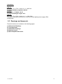
3.14 Power Supply
The NAUTICAST™ must be supplied from the emergency power source. A new battery
capacity calculation must be undertaken. See sample in 9.1 (Samples for battery calculation)
Following documents are needed for the installation approval of the classification
Antenna Layout (arrangement)
Battery Calculation
Connection / Block – Diagram with locations
Type Approval Certificate
Y1-03-0212H
33
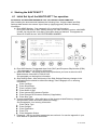
4 Starting the NAUTICAST™
4.1 Initial Set Up of the NAUTICAST™ for operation
ATTENTION: AUTHORITIES MANADATE THAT YOU ENTER THIS INFORMATION.
After installing the antennas and hardware the following User, Voyage related and Ship
Settings data needs to be entered. Upon Start-up (Applying power) enter the following
information.
a) Enter MMSI Number - See paragraph 4.2 on entering information.
During the initial boot or after “factory settings” the user is asked to enter a valid MMSI
number. As long as this is not done, the system does not transmit. This appears as
Alarm-ID 56 with the text “AIS: ENTER MMSI NUMBER”.
LAT: N/A
LON: N/A
IntN/A:
SOG: N/A
COG: N/A
STOP
00/00/00
24:60:60
! 7A 1T
++++++++++++++++++++++++++++++++++++++++
Time 24:60 00/00
[!] ALARM ID:56
AIS: ENTER MMSI NUMBER
Please press OK to enter MMSI number!
Tx temporary suppressed
++++++++++++++++++++++++++++++++++++++++
---------------------------------------|
OK
|
|
|
b) Enter IMO Number, Designated Area Code (DAC) and European Ship Number (ESN)
- See paragraph 4.2 on Entering information.
c) Select AIS Mode – According to the local requirements you have to select the AIS
Mode between Inland AIS or SOLAS AIS.
See paragraph on altering this information.
d) Ship Settings Data - After initial entry of the Ship Settings Data any changes in the
information below should be edited accordingly. See Paragraph 4.3 on entering
information.
Enter Call Sign
Enter Ships Name
Enter Length of Ship
Enter Beam of Ship
Enter Internal GPS antenna Position
Enter External GPS Antenna Position (If Applicable).
Enter Ship Type
e) Voyage related Data – After initial entry of the Voyage related Data any changes in
the information below should be edited accordingly.
See Paragraph 4.4 on entering information.
Enter Cargo Type
Enter Draught
Enter Destination
Enter ETA
Enter Navigation Status.
f) Password – Service and User passwords see section 4.6 or see the appendix in your
User Manual for password information.
34
Y1-03-0212H
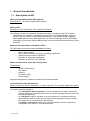
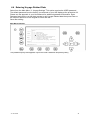
4.2 Entering the MMSI / IMO / DAC / ESN Numbers
Select from the Main Menu “Service Configuration” Number 6. This option requires the
SERVICE password. The default password from the factory is mentioned on your AIS display
at the protection foil. Please see the appendix in your User Manual for additional password
information. Enter Service Password and use the up and down arrows on keypad to select
“Change MMSI / IMO” than press M5 “Select” or “by pressing number 3 on the keypad.
Input your MMSI and IMO number and press Save to store data. Unit will reboot itself after
pressing Save. Continue to 4.2 after reboot.
N 1o19' E 0o13' |1>0.01|2>1.30|3>1.80nm
|---------------------------------| Menu
-----| |
| +- 1. Messages
View | +- 2. AIS Status
| +- 3. Voyage Settings
-----| +- 4. Ship Settings
| +- 5. Transponder Configuration
Msg. | +- 6. Service Configuration
| +- 7. Display Settings
-----| +- 8. Graphical Display Settings
|
Displ|
---------------------------------------NUM|Select->|
|
|<-Back
Service Configuration Menu Example:
N 1o21' E 0o14' |1>0.01|2>1.30|3>1.80nm
|---------------------------------| 6. Service Configuration
-----| |
| +- 1. Change Service Password
View | +- 2. User Password Settings
| +- 3. Change MMSI / IMO
-----| +- 4. Change DAC / ESN
| +- 5. Change AIS Mode
Msg. | +- 6. Restore Factory Settings
|
-----|
|
Displ|
---------------------------------------NUM| Select->|
|
|<-Back
Note: MMSI and IMO Data input are limited to 9 characters.
Y1-03-0212H
35
N 1o21' E 0o14' |1> N/A|2>0.00|3>0.10nm
********** Change MMSI / IMO ***********
MMSI
:119302468
IMO No.:303174162
---------------------------------------NUM| Save |
|
| Back
Select Submenu 4 “Change DAC / ESN” with cursor button [Up] & [Down] by pressing Nr. 4
on the keyboard.
N 1o21' E 0o14' |1>0.01|2>1.30|3>1.80nm
|---------------------------------| 6. Service Configuration
-----| |
| +- 1. Change Service Password
View | +- 2. User Password Settings
| +- 3. Change MMSI / IMO
-----| +- 4. Change DAC / ESN
| +- 5. Change AIS Mode
Msg. | +- 6. Restore Factory Settings
|
-----|
|
Displ|
---------------------------------------NUM| Select->|
|
|<-Back
Input new DAC / ESN Numbers and press [Save] to store input data. Press [Back] to return to
the Submenu without saving.
Note: The DAC (Designated Area Code) is predefined with the value “200”. Please key in
only a different 3 digit value if your authority wants you to do this. Otherwise you may lose
important AIS information. The ESN (European Ship Number) is limited to 8 ASCII
characters.
N 1o21' E 0o14' |1> N/A|2>0.00|3>0.10nm
*********** Change DAC / ESN ***********
DAC
ESN
: 200
: A123456B
---------------------------------------NUM| Save |
|
| Back
36
Y1-03-0212H
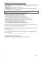
4.3 Entering Ship Settings
Select from the Main Menu “4. Ship Settings” This option requires the USER password. The
default password from the factory is mentioned on your AIS display at the protection foil.
Please see the appendix in your User Manual for additional password information. Enter
Password and use the up and down arrows to edit Ship Settings then press Enter or the
numeric reference on the keypad to select and edit.
Save after editing.
Main Menu Example:
N 1 o23' E 0 o16' |1>0.01|2>1.30|3>1.80nm
|---------------------------------| Menu
-----| |
| +- 1. Messages
View | +- 2. AIS Status
| +- 3. Voyage Settings
-----| +- 4. Ship Settings
| +- 5. Transponder Configuration
Msg. | +- 6. Service Configuration
| +- 7. Display Settings
-----| +- 8. Graphical Display Settings
|
Displ|
---------------------------------------NUM|Select->|
|
|<-Back
Select Ship Settings and press M5 [Enter]. Enter User Password and Continue.
Ship Settings Menu Example:
N/A
N/A
|1> N/A|2> N/A|3> N/Anm
*********** Convoy Settings ************
Call Sign:OEZ1234
/\ +
ShipName :INLAND SHIP
/
\|
Ref.Points ext
int
|
|
A: 200m
220m
|
A
B:
20m
N/A
|
|
C:
10m
10m
|
+--|
D:
33m
33m
|
| B
Len (A+B): 220m
220m
|
| |
Beam(C+D):
43m
43m
+-C-+D-+
Len [dm]: 2199dm
Beam [dm]: 429dm
>>> DATA OK. PRESS M5 TO SAVE DATA <<<
---------------------------------------| Save |
|
| Back
Select and enter Call Sign (ATIS).
Select and enter Ship Name.
Enter external GPS Antenna Position
Enter internal GPS Antenna Position
Enter ship len and beam in [dm]
Y1-03-0212H
37
Setting the Internal and External GPS Antenna Position.
Note: It is critical for the proper orientation of your ship to other AIS users to enter this
data accurately.
Example: Length of ship = 220m and Beam = 43m.
GPS ANTENNA location on ship (is x in above Menu example) is located 200 meters from
bow (A) and 33 Meters from Starboard side (D).
Note: If no external GPS is connected, then enter same data as for internal GPS. External
GPS antenna reference point must be filled in before you can save.
Ref.Points ext (Position of the external GPS antenna)
A = 200m the distance from bow (front) to the antenna.
B= 20m the distance from the antenna to the stern (rear)
C = 10m the distance from the port (left) side to the antenna
D = 33m the distance from the antenna to the starboard (right) side
Enter Ref.Point int (location of the internal GPS antenna) in the same way.
A = 220m the distance from bow (front) to the antenna.
B= 0m the distance from the antenna to the stern (rear)
C = 10m the distance from the port (left) side to the antenna
D = 33m the distance from the antenna to the starboard (right) side
Your int/ext reference points must match the entered ship dimensions. Length of ship = 220m
and Beam = 43m. For incorrect dimension the AIS shows:
>>> ext/int ship len/beam don't match
Rounded up value of Len and Beam in [dm] must match Len (A+B) and Beam (C+D) in [m]
other the AIS shows:
>>> Convoy len must match rounded A+B
After correct settings of the reference points and dimensions you can press M5 - [Save]. to
save your settings:
>>> DATA OK. PRESS M5 TO SAVE DATA <<<
Save the new settings by pressing [Save].
Press [Back] return to the Main Menu Screen without saving any changes.
38
Y1-03-0212H
4.4 Entering Voyage Related Data
Select from the Main Menu “3. Voyage Settings” This option requires the USER password.
The default password from the factory is mentioned on your AIS display at the protection foil.
Please see the appendix in your User Manual for additional password information. Enter
Password and use the up and down arrows to edit Voyage Related data then press Enter or
the numeric reference on the keypad to select and edit.
Save after editing.
Main Menu Example:
N 1 o20' E 0 o13' |1> N/A|2>0.00|3>0.10nm
|---------------------------------| Menu
-----| |
| +- 1. Messages
View | +- 2. AIS Status
| +- 3. Voyage Settings
-----| +- 4. Ship Settings
| +- 5. Transponder Configuration
Msg. | +- 6. Service Configuration
| +- 7. Display Settings
-----| +- 8. Graphical Display Settings
|
Displ|
---------------------------------------NUM|Select->|
|
|<-Back
The password query field appears. Input new User Password and press [Enter].
Y1-03-0212H
39
N 1 o31' E 0 o24' |1>0.01|2>1.30|3>1.80nm
---------------------------------------++++++++++++++++++++++++++++++++++++++++
User password protected!
Please enter user password:
++++++++++++++++++++++++++++++++++++++++
---------------------------------------| Enter |
|
| Exit
Select Submenu 1 “General Settings” with cursor button [Up] & [Down] by pressing Nr. 1 on
the keyboard.
N 1 o18' E 0 o12' |1>0.01|2>1.30|3>1.80nm
|---------------------------------| 3. Voyage Settings
-----| |
| +- 1. General Settings
View | +- 2. Cargo / Voyage
| +- 3. Persons on Board
-----| +- 4. Destination
|
Msg. |
|
-----|
|
Displ|
|
---------------------------------------NUM|Select->|
|
|<-Back
Scroll the Data Fields with [Enter] and input own vessel data. Enter draught in meter (max. =
20.0m), and air-draught value in centimetre (max. = 4000cm) as well as the correct
navigational status setting. Running AIS in high sea mode allows draught of 25.5m
Save the new settings by pressing [Save], and return to the Main Menu Screen by pressing
[Exit]. Press [Back] to return to the Main Menu without saving any changes.
N48^12' E 16^26' |1> N/A|2> N/A|3> N/Anm
******* General Settings / Tx1W ********
Draught[x.xx m]:N/A
Airdraught[cm] :N/A
NavStat.
: Undefined
1 Watt
: Off
> NavStat
: NOK (Moored)
> SOG
: NOK ( <3kn )
> ShipType
: NOK (Tanker)
---------------------------------------NUM| Save |
|
| Exit
40
Y1-03-0212H
Select Submenu 2 “Cargo/Voyage Settings” with cursor button [Up] & [Down] or by pressing
Nr. 2 on the keyboard.
Toggle the values for the ERI ship type (see section 7.1), the hazardous cargo by the
number of Blue Cones [0-3, B-Flag, Default/Unknown], and the loaded / unloaded status Un/
Loaded [Loaded, Unloaded].
Save the new settings by pressing [Save], and return to the Main Menu Screen by pressing
[Exit]. The ERI ship types, which are used in Inland message 10, are automatically converted
to the IMO types which are used in IMO message 5 (refer to section 7.1.).Press [Back] to
return to the Main Menu without saving any changes.
N48^12' E 16^26' |1> N/A|2> N/A|3>0.00nm
******** Cargo/Voyage Settings *********
ERI ship type :<Vessel, type unknown>
SOLAS shiptype: N/A or no ship
Cargo type
: - - Blue cones
: Default/Unknown
(Un) Loaded
: Default/Unknown
---------------------------------------| Save |
|
| Exit
Select Submenu 3 “Persons on Board” with cursor button [Up] & [Down] or by pressing Nr. 2
on the keyboard.
N 1o18' E 0o12' |1>0.01|2>1.30|3>1.80nm
************* PoB Settings *************
Crew Members:0-254 (255 = unknown = default)
Passenger
:0-8190(8191= unknown = default)
S. Personal :0-254 (255 = unknown = default)
-------------------------Total
:nnnn
Members
M6: Send addressed PoB Message
M7: Broadcast PoB Message
---------------------------------------Num| Save |Addressed |Broadcast | Exit
Note: The total number of persons on board will be calculated automatically. In “High Seas”
mode this sum will be used for the AIS messages.
How to use this menu to transfer PoB – information will be described in detail in the User Manual.
Y1-03-0212H
41
Select Submenu 4 “Destination” with cursor button [Up] & [Down] by pressing Nr. 4 on the
keyboard.
Select between mask input and direct input of the destrination string.
Mask input:
Scroll the Data Fields with [Enter] and input the UN destination codes as well as the ETA
(estimated time of arrival) data.
Save the new settings by pressing [Save], and return to the Main Menu Screen by pressing
[Exit]. Press [Back] to return to the Main Menu without saving any changes.
N 1o18' E 0o12' |1>0.01|2>1.30|3>1.80nm
************* Destination***************
use mask [*]/[ ] input string
UN Country
:NL
UN Location
:DOR
Fairway section:02552
Terminal code :LEUVE
Fairway hector :00000
ETA(MMDDhhmm) :10/31 10:05
---------------------------------------| Save |
|
| Exit
String Input:
Direct input of all entries above as string.
NOTE: All characters are allowed. Its in the users responsibility to enter the correct length for all
entries. The above mask would be entered as:
N 1o18' E 0o12' |1>0.01|2>1.30|3>1.80nm
************* Destination***************
use mask [ ]/[*] input string
Destination
ETA(MMDDhhmm)
:NLDOR02552LEUVE00000
:10/31 10:05
---------------------------------------| Save |
|
| Exit
The ETA must be entered separately in the according field.
42
Y1-03-0212H
4.5 Entering Inland AIS Configuration
Select from the Main Menu “5. Transponder Configuration” This option requires the USER password.
The default password from the factory is mentioned on your AIS display at the protection foil. Please
see the appendix in your User Manual for additional password information. Enter User Password and
press [Enter] or [M5].
N48^12' E 16^26' |1> N/A|2> N/A|3> N/Anm
|---------------------------------| Menu
-----| |
| +- 1. Messages
View | +- 2. AIS Status
| +- 3. Voyage Settings
-----| +- 4. Ship Settings
| +- 5. Transponder Configuration
Msg. | +- 6. Service Configuration
| +- 7. Display Settings
-----| +- 8. Graphical Display Settings
|
Displ|
---------------------------------------NUM|Select->|
|
|<-Back
Y1-03-0212H
43
Select Submenu 7 “Inland AIS Configuration” with cursor button [Up] & [Down] by pressing
Nr. 7 on the keyboard.
N48^12' E 16^26' |1> N/A|2> N/A|3> N/Anm
|---------------------------------| 5. Transponder Configuration
-----| |
| +- 1. Change User Password
View | +- 2. Region Settings
| +- 3. Alarm Settings
-----| +- 4. Interrogation Settings
| +- 5. Sensor Settings
Msg. | +- 6. GPS Settings
| +- 7. Inland AIS Configuration
-----|
|
Displ|
---------------------------------------NUM|Select->|
|
|<-Back
This screen allows the user to toggle the quality of the speed, course or heading information received
from an external device. These settings are normally set to low.
Note: It is highly recommended to keep the settings to low.
Blue Sign:
Toggle the value from <not available> to <used> when a Blue Sign switch is connected. Setting the
blue sign can be done by an external hardware switch. Please see the chapter 3.12 how to connect
the blue sign - cable 2635 (NAU-B502) which includes and RS232 connector as well. Unless you
configure the Blue Sign appropriate, you may not be able to use it.
BlueSign
Blue Sign
<not available> no blue sign switch is connected
<used> when a blue sign switch is connected
N48°12' E 16°26' |1> N/A|2> N/A|3> N/Anm
******* Inland AIS Configuration *******
Quality information
Speed : Low
Course : Low
Heading: Low
BlueSign :<used>
---------------------------------------| Save |
|
| Exit
44
Y1-03-0212H
4.6 Service and User Passwords
WARNING: It is very important that the Service password not be lost. Keeping the
password in a second location may be wise. Record your custom service and user passwords
in the table provided in the appendix of your User Manual. Memorizing the password is best.
If you lose this password, you cannot make any further configuration changes: Access to the
AIS is blocked. Another master key is not available and the unit would have to be returned to
the ACR Service centre. This service is not free of charge.
Once you have entered the system, please change the default password to your own
passwords, for both levels of access. Use different passwords for the different security levels.
Your passwords must meet the following criteria:
Minimum of six (6) characters, maximum of eight (8) characters
Letters must be in UPPER CASE
Acceptable characters are the A-Z alphabet and 0- 9 digits
Password may contain both letters and numbers
The User Password can be reset in the service configuration menu by entering the Service
Configuration menu and creating a new password.
Changing the Service Password
Select “Service Configuration” from the Main Menu with the cursor button [Up] & [Down] or
press Number 6 on the keyboard.
The password query field appears. Input default Service Password and press M5 [Enter]. The
default password from the factory is mentioned on your AIS display at the protection foil.
Please see the appendix in your User Manual for additional password information.
N 1o24' E 0o17' |1>0.10|2>1.30|3>1.80nm
---------------------------------------++++++++++++++++++++++++++++++++++++++++
Service password protected!
Please enter service password:
++++++++++++++++++++++++++++++++++++++++
---------------------------------------| Enter |
|
| Exit
Select Submenu 1 “Change Service Password” with cursor button [Up] & [Down] by pressing
Number 1 on the keyboard.
Y1-03-0212H
45
Service Menu Example:
N48^12' E 16^26' |1>0.00|2>0.00| * 2S
|---------------------------------| 6. Service Configuration
-----| |
| +- 1. Change Service Password
View | +- 2. User Password Settings
| +- 3. Change MMSI / IMO
-----| +- 4. Change DAC / ENI
| +- 5. Change AIS Mode
Msg. | +- 6. Restore Factory Settings
|
-----|
|
Displ|
---------------------------------------NUM|Select->|
|
|<-Back
Service Password Menu Example:
N 1o25' E 0o18' |1>0.10|2>1.30|3>1.80nm
******* Change Service Password ********
Enter new password :
Repeat new password:
{Length: 4..8 characters}
---------------------------------------| Save |
|
| Back
Enter the new Password: Then push Enter (M5).
Repeat the new Password: Then Push Enter (M5).
A minimum of 6, a maximum of 8 characters are allowed. Should the new password include
numbers, use the shift key to generate them.
Press Save to store the change.
Changing the User Password
Select Submenu 2 “User Password Settings” with cursor button [Up] & [Down] by pressing
number 2 on the keyboard.
46
Y1-03-0212H
N48^12' E 16^26' |1>0.00|2>0.00| * 2S
|---------------------------------| 6. Service Configuration
-----| |
| +- 1. Change Service Password
View | +- 2. User Password Settings
| +- 3. Change MMSI / IMO
-----| +- 4. Change DAC / ENI
| +- 5. Change AIS Mode
Msg. | +- 6. Restore Factory Settings
|
-----|
|
Displ|
---------------------------------------NUM|Select->|
|
|<-Back
Select Submenu 1 “Change User Password” with cursor button [Up] & [Down] by pressing
Number 1 on the keyboard.
N 1o21' E 0o14' |1>0.01|2>1.30|3>1.80nm
|---------------------------------| 6-2. User Password Settings
-----| |
| +- 1. Change User Password
View | +- 2. Change Password Protection
|
-----|
|
Msg. |
|
-----|
|
Displ|
---------------------------------------NUM| Select->|
|
|<-Back
Enter the new Password:
Repeat the new Password:
A minimum of 6, a maximum of 8 characters are allowed. Should the new password include
numbers, use the shift key to generate them.
N 1o25' E 0o18' |1>0.10|2>1.30|3>1.80nm
******* Change User Password ***********
Enter new password :
Repeat new password:
{Length: 4..8 characters}
---------------------------------------| Save |
|
| Back
Press Save to store the changes.
Y1-03-0212H
47
5 Troubleshooting
5.1 Reading and understanding Alarms:
The NAUTICAST differentiates between Alarm and TXT messages. An Alarm informs the
user about major system malfunctions and failings in the connected sensors.
The Alarm Status informs the user about all active Alarms. The Alarm will be disabled and
deleted from the Alarm Status, as soon as the displayed problem has been rectified.
The TXT status displays additional sensor information and the UTC clock status.
See tables (Section 5.2 and 5.3) for Alarm and TXT Messages.
Select “AIS Status” with cursor button [Up] & [Down]
or press Number 2 on the keyboard.
N 1o19' E 0o12' |1> N/A|2>0.00|3>0.10nm
|---------------------------------| Menu
-----| |
| +- 1. Messages
View | +- 2. AIS Status
| +- 3. Voyage Settings
-----| +- 4. Ship Settings
| +- 5. Transponder Configuration
Msg. | +- 6. Service Configuration
| +- 7. Display Settings
-----| +- 8. Graphical Display Settings
|
Displ|
---------------------------------------NUM|Select->|
|
|<-Back
Select “Alarm Status” or “TXT Status” with cursor button [Up] & [Down]
or press Number 4 or 5 on the keyboard.
N 1o21' E 0o14' |1> N/A|2>0.00|3>0.10nm
|---------------------------------| 2. AIS Status
-----| |
| +- 1. State / Conditions
View | +- 2. Own Ship Data
| +- 3. Own VHF Status
-----| +- 4. Alarm Status
| +- 5. TXT Status
Msg. | +- 6. Version Info
| +- 7. Security Log
-----|
|
Displ|
---------------------------------------NUM|Select->|
|
|<-Back
48
Y1-03-0212H
5.2 Alarm Codes
ID
Description Text
01 AIS: Tx malfunction
Cause/Source
VHF Antenna,
cabling
AIS: Antenna VSWR exceeds limit
VHF antenna,
02 (VSWR - Voltage Standing Wave
installation
Ratio)
03 AIS: Rx channel 1 malfunction
04 AIS; Rx channel 2 malfunction
Internal error
05 AIS: Rx channel 70 malfunction
06 AIS: General failure
AIS; External EPFS lost (EPFS =
25 electronic Position Fixing System
such as GPS)
Reaction: The transponder unit stops transmission.
Remedy;
The transponder unit requires replacing.
Reaction: The transponder unit continues operation using the position data
of the internal GPS. If there is no valid position data available from the
No valid data on internal GPS, error 026 is additionally displayed.
Remedy:
Ch1, Ch2 or Ch3 Id 25 indicates that the sentences GLL, GNS, GGA, RMC cannot be
is available
received. Check the sensor and the cabling; check if the system that delivers
the data is working. Check the baud rate settings of the sensor inputs. AIS
requires the protocol NMEA 0183 V3.0!
No valid position
from internal
GPS or external
position sensor
29 AIS: No valid SOG information
No valid data
from external
speed sensor or
internal GPS
32 AIS: Heading lost/invalid
35 AIS: No valid ROT Information
53 AIS: BATTERY SOON LOW
55
AIS: PRESS ENTER TO EXIT
1W/AUTO TX MODE
56 AIS: ENTER MMSI NUMBER
Y1-03-0212H
Reaction: The transponder unit stops transmission on the affected channel,
Remedy;
If this alarm reoccurs regularly, then the transponder unit requires replacing.
Internal error
26 AIS: No sensor position in use
30 AIS: No valid COG Information
System Reaction / Remedy
Reaction: The transponder unit stops transmission. If Alarm ID 01 and ID 02
are simultaneously displayed, then a major antenna problem has arisen.
Remedy:
Check if the antenna is AIS compatible (156-162 MHz) and if the antenna
cabling has a short circuit or is missing any contacts at the connectors.
If the ID 01 is displayed as a stand alone message, then the unit requires
replacing.
Reaction: The transponder unit continues transmission.
Remedy:
Check the antenna and the antenna cabling (RG214 / 50 Ohm cable
required).
Reaction: The transponder unit continues operation.
Remedy:
Check the sensor cabling and the antenna of the internal GPS sensor.
Reaction: The transponder unit continues operation and displays SOG: N/A
Remedy:
The sentences VBW, VTG, RMC cannot be received. Check the sensor and
the cabling; check if the system that delivers the data is working. Check the
baud rate settings of the sensor inputs. AIS requires the protocol NMEA
0183 V3.0!
Reaction: The transponder unit continues operation and displays COG: N/A
No valid data
Remedy:
from external
The sentences VBW, VTG, RMC cannot be received. Check the sensor and
sensor or internal the cabling, check if the system that delivers the data is working. Check the
baud rate settings of the sensor inputs. AIS requires the protocol NMEA
GPS
0183 V3.0!
Reaction: The transponder unit continues operation
No valid data
Remedy:
from external
The sentence for HDT cannot be received. Check the sensor and the
cabling, check if the system that delivers the data is working. Check the baud
sensor
(Gyrocompass) rate settings of the sensor inputs. Mention AIS accepts true heading only (no
magnetic).
Reaction: The transponder unit continues operation
No ROT indicator Remedy:
The sentence for ROT cannot be received. If a Rate Of Turn indicator is not
is used.
in use, then it suffices to just acknowledge the alarm. The Alarm Status will
No valid data
store the information that no ROT sensor is available. Otherwise, check the
from external
sensor and the cabling. Check if the system that delivers the data is working.
sensor
Check the baud rate settings of the sensor inputs. The AIS requires the
protocol NMEA 0183 V3.0!
Battery is soon
Reaction: Own ship data is lost after powering on/off the system.
Remedy: consider to contact Technical Support for additional help
out of capacity
Reaction: Conditions for enabling 1 Watt TX power are not valid.
This means that:
Conditions for
the speed is >3kn and / or
the navigational status is NOT moored / at anchor and / or
enabling 1 Watt
the ship type is NOT “Tanker”
TX power are not
Remedy:
valid
Check the conditions (SOG, Navstat, Shiptype)
if GPS is valid ( a invalid GPS causes also this alarm)
Reaction: During the initial boot or after “factory settings” the user is asked to
No valid MMSI
enter a valid MMSI. As long as this is not done, the system does not
transmit.
entered.
Remedy: Enter a valid MMSI
49
5.3 Text Messages
ID
Description Text
Cause/Source
Reaction of the System / Remedy
07
AIS: UTC clock lost
Internal GPS
Reaction: the transponder unit continues operation using indirect or
semaphore synchronisation
Remedy:
Check GPS Antenna for AIS.
21
AIS: external DGNSS in use
Information
Reaction: Positioning is fully operational
Remedy: no action required
22
AIS: external GNSS in use
Information
Reaction: The transponder unit continues operation using the position data
from a GNSS receiver
Remedy: no action required
AIS: internal DGNSS in use
(beacon) 023
AIS: internal DGNSS in use
(message 17)
Information
Reaction: The transponder unit uses position data from the internal source.
The internal GNSS receiver is capable of processing DGNSS corrections.
Remedy: no action required
25
AIS: internal GNSS in use
Information
additional to
Alarm ID 25
Reaction: The transponder unit continues operation using the position data
from the internal GPS.
Remedy
Check the sensor and the cabling; Check if the system that delivers the data
is working; Check the baud rate settings of the sensor input
27
AIS: external SOG/COG in use
Information
Reaction: COG/SOG is in full operation
Remedy: no action required
28
AIS: internal SOG/COG in use
Information
additional to
Alarm ID 29 or
ID 30
Reaction: The transponder unit continues operation using the data from the
internal GPS.
Remedy:
Check the sensor and the cabling; Check if the system that delivers the data
is working; Check the baud rate settings of the sensor inputs
31
AIS: Heading valid
Information
Reaction: Heading is in full operation
Remedy: no action required
33
AIS: Rate of Turn Indicator in use
Information
Reaction: A Rate Of Turn indicator is connected and in full operation
Remedy: no action required
34
AIS: Other ROT source in use
Information
Reaction: The transponder unit is operating with ROT data rather than with
TIROT data - therefore the AIS only differs between
+ 127 (turning right at 720 degrees per minute or higher) and
– 127 (turning left at 720 degrees per minute or higher)
23
24
5.4 Restarting the NAUTICAST™
The NAUTICAST™ can be restarted during operation by pressing the keys “Shift” + “Fn” +
“Del” simultaneously. It may take up to 6 minutes to receive all information from other ships
again because of their reporting interval.
50
Y1-03-0212H
6 Accessories
The following material is included with the NAUTICAST™.
1 NAUTICAST™ Inland AIS Transponder
1 installation manual, 1 user Manual
3 caps of plug
1 cable clamp (M5 thread)
1 guide plate Kit
3 angles + 3 mounting screws (screw bolt + square nut)
The NAUTICAST™ Inland AIS is supplied with some of the components listed below
(contents depend on customer requirements).
PRODUCT
NUMBER
2610
2611
2614
2617
2612
2613
2628
2621
2622
2623
2624
2630
2631
2632
2633
2640
2642
2650
2651
2652
Y1-03-0212H
PRODUCT DESCRIPTION
AIS Cable
AIS Interface Cable (Power & Data) between Transponder and Connection Box & Pilot Plug, 3
meters (9.8ft) Halogen Free, IP67
AIS Interface Cable (Power & Data) between Transponder and Connection Box & Pilot Plug, 10
meters (32.8ft) Halogen Free. IP67
AIS Interface Cable (Power & Data) between Transponder and ECS, 1.5 meters (4.9ft)
AIS Interface Cable (Power & Data) between Transponder and PC 1.5 meters (2 sensor only)
GPS/VHF Cable
GPS/VHF Interface Cable, 1meter (3.3ft) Includes 1 each Female N and TNC connectors installed
and 1 each Male N and TNC connectors for RG214 cable (specify length) Not Required with P/N
2624 VHF/GPS Combi Antenna.
GPS/VHF Interface Cable, 10 meters( 32.8ft) Includes 1 each Male PL & TNC connector installed.
(Not Required with P/N 2624 VHF/GPS Combi Antenna.)
ACR VHF Antenna Solution
VH-3200 VHF Stainless Steel Whip Antenna 91.4cm (36in) Includes Mounting Kit & Plug PL Male
for RG214
Comrod AV 7 VHF Fiberglass Antenna 1.22m(4ft) Includes Aluminum mount (Vert or Horiz..
stanchion, or bulkhead) When used with P/N 2612, 1 P/N 2632 PL Male Connector & P/N 2630
cable (specify length) are required.
ACR GPS Antenna Solution
ProCom GPS4 Quadrifilar Helix Antenna 5 Volt. When used with P/N 2612 interface, one P/N
2633 TNC Connector & P/N 2630 cable (Specify length) are required. Mount P/N 2623 is required.
ProCom FLG Deck Mounting Kit Metal Horiz.. surface (for P/N 2622)
ACR VHF/GPS Combination Antenna Solution (in lieu of individual VHF and GPS antenna
solutions)
Comrod AC17 Combi Antenna (combined GPS/VHF) includes Aluminum mount (Vert or Horiz..
Stanchion or bulkhead) & 1m interface cable. If longer cable required, order P/N 2630 cable
(specify length) and 2 P/N 2631 Male N connectors. P/N 2612 or 2613 are not required with this
option.
Optional VHF/GPS Antenna Cable extensions and Plugs (select or supply own cable)
GPS/VHF RF Antenna Cable extension cable RG214 (No Plugs) Sold per meter
N Male RG214 Crimp
PL Male RG214 Crimp
TNC Male RG214 Crimp
Optional AIS Cable Connection Box (Required for Advanced Installation with ECDIS, etc.)
Connection Box
Optional 12vt to 24vt DC to DC Converter ( Required for 12vt power systems)
12v to 24v DC to DC Power Converter.
Optional Mounting Bracket Assemblies for UAIS Nauticast™
Mounting Bracket Gimbal Style (Includes 4 screws and 2 Mounting Knobs)
Retro Fit Frame Drop In Mount (Includes 3 screws, nuts, clips to hold display to bracket)
Frame for Rack Mount. 48.3cm (19in) Includes 3 Bolts and Nuts to hold display to bracket.
Discontinued
51
7 Technical Information
PHYSICAL
Size in mm / inch (w)
Size in mm / inch (h)
Size in mm / inch (d)
Weight
Operating Temperature
281,26mm / 11,07inch
60mm
/ 2,36inch
201,26mm / 7,92inch
2490g / 5,50pound
-15°C to +55°C / 5°F to 131°F
POWER SUPPLY
Supply Voltage (galvanic isolated)
Input Current
24 V DC (-10% +30%)
min.7 A (24V)
INTERFACES
Number of Data Ports
IEC 61162-1/2
ITU-R M.823-2
Bitrate
CH1 Sensor Input; (i.E.: GPS)
CH2 Sensor Input; (i.E.: GYRO)
CH3 Sensor Input; (i.E.: HDG)
CH4 ECDIS Port (In- / Output)
AIS targets, AIS messages
CH5 Pilot Port (In- / Output)
AIS targets, AIS messages
CH8 Long Range Port (In- /
Output)
CH9 DGPS correction (In- /
Output) (RTCM SC104)
Alarm Circuit CH10
3 Input / 4 I-O / 1 Output
( RS422 / NMEA 0183)
( RS422 / RTCM SC104)
4800 bps or 38400 bps
4800 bps or 38400 bps
4800 bps or 38400 bps
in/ out 38400 bps
in/out 38400 bps
in/out 38400 bps
in/out 9600 bps
Dry relay contact (see BIIT –
Alarm System)
Blue Sign Switch
16 channel differential
16 satellites sim.
2.5m CEP
2.0m CEP
TNC
Beacon Interoperability
EGNOS Interoperability
WAAS Interoperability
OMNISTAR Interoperability
LongWave Interoperability
VHF interop. (DGPS over Msg.17)
BIIT – Alarm System
OPTIONAL INTERFACES
Number of Data Ports RS232
Bitrate
Simplex / Duplex
Number of Data Ports IEC
61162-3 CAN (RS485)
Bitrate
KEYBOARD
Integrated
52
VHF TRANSMITTER
Output Power
Receive to Transmit Switching Time
Transmit release time
Automatic shutdown
Channel switching time
Attack Time
Adjacent Channel Selectivity
Inter-modulation Rejection
Spurious Response Rejection
Blocking
VHF MODEM
Bitrate GMSK
RF Baud Rate (DSC)
Modulation
GPS Solutions
Relay breaking capacity
30V DC
250V AC
VHF
Frequency Range
Channel Spacing
Number of RF Channels
Number of AIS Receivers
Number of DSC Receivers
Frequency Error
VHF RECEIVER
Max. Useable Sensitivity
Co-channel Rejection
BUILT IN GPS
Receiver Architecture
Tracking Capability
Accuracy
Accuracy DGPS/SBAS
GPS Antenna Connector
SPECIFIED STANDARDS
IMO MSC.74(69) Annex 3
ITU-R M.1371-3 (Class A)
IALA Techn.Clar. of ITU-R M.1371-1
(Ed.1.3)
IEC 61993-2 (2002)
IEC 61162-1 (2000)
IEC 61162-2 (1998)
IEC 61162-3
ITU-R M.823-2
IEC 61108-1 (1996)
IEC 60 945 (1996)
ITU-R M.825-3
ITU-R M.1084-3
8A
8A
up to 5
Up to 115000 bps
Duplex
1
up to 1 Mbps
NMEA 0183-3
NMEA 0183-3
NMEA 2000
VTT&T
156 MHz - 162MHz
12.5 or 25kHz
3 Receiv. / 1 Transm.
2
1
+/- 2.5ppm
1 Watt to 12.5 Watt
(adjustable)
< 1ms
< 1ms
1 sec.
< 25ms
< 1ms
< -110dBm
> -8dB (25kHz);
> -12dBm (12.5kHz)
> 70dB (25kHz);
> 60dB (12.5kHz)
> 65dB
> 70dB
> 84dB
9600 bps
1200bps
GMSK / FSK
SOFTWARE
NAUTICAST™ Inland AIS Version 2.0.x
- installed and ready for use
- implemented configuration Software
- User friendly Interface
to System and AIS Information
- additional Interface to System
Configuration
(Windows 2000®)
- NAUTICAST™ Demonstrator
for training purposes
(Windows 2000 Windows XP®)
HARDWARE
NAUTICAST™ Version 1.0.x
DISPLAY
Integrated
Text 40x16 chars
graphical 240 x 128
adjustable brightness
and contrast
alphanumerical
Y1-03-0212H
7.1 ERI Ship Types
Msg 5 (1-99)
code U ship name
Ship Type - SOLAS
dig1
dig2
Type (first digit)
Cargo (Second digit)
8000 No Vessel, type unknown
9
9
Other types of Ship
No additional information
8010 V Motor freighter
7
9
Cargo Ships
No additional information
8020 V Motor tanker
8
9
Tanker
No additional information
8021 V Motor tanker, liquid cargo, type N
8
0
Tanker
All ships of this type
8022 V Motor tanker, liquid cargo, type C
8
0
Tanker
All ships of this type
8023 V Motor tanker, dry cargo as if liquid (e.g. cement)
8
9
Tanker
No additional information
8030 V Container vessel
7
9
Cargo Ships
No additional information
8040 V Gas tanker
8
0
Tanker
All ships of this type
8050 C Motor freighter, tug
7
9
8060 C Motor tanker, tug
8
9
Tanker
No additional information
8070 C Motor freighter with one or more ships alongside
7
9
Cargo Ships
No additional information
8080 C Motor freighter with tanker
8
9
Tanker
No additional information
8090 C Motor freighter pushing one or more freighters
7
9
Cargo Ships
No additional information
8100 C Motor freighter pushing at least one tank-ship
8
9
Tanker
No additional information
8110 No Tug, freighter
7
9
Cargo Ships
No additional information
8120 No Tug, tanker
8
9
Tanker
No additional information
8130 C Tug freighter, coupled
3
1
Vessel
Towing
8140 C Tug, freighter/tanker, coupled
3
1
Vessel
Towing
8150 V Freightbarge
9
9
Other types of Ship
No additional information
8160 V Tankbarge
9
9
Other types of Ship
No additional information
8161 V Tankbarge, liquid cargo, type N
9
0
Other types of Ship
All ships of this type
8162 V Tankbarge, liquid cargo, type C
9
0
Other types of Ship
All ships of this type
8163 V Tankbarge, dry cargo as if liquid (e.g. cement)
9
9
Other types of Ship
No additional information
8170 V Freightbarge with containers
8
9
Tanker
No additional information
8180 V Tankbarge, gas
9
0
Other types of Ship
All ships of this type
8210 C Pushtow, one cargo barge
7
9
Cargo Ships
No additional information
8220 C Pushtow, two cargo barges
7
9
Cargo Ships
No additional information
8230 C Pushtow, three cargo barges
7
9
Cargo Ships
No additional information
8240 C Pushtow, four cargo barges
7
9
Cargo Ships
No additional information
8250 C Pushtow, five cargo barges
7
9
Cargo Ships
No additional information
8260 C Pushtow, six cargo barges
7
9
Cargo Ships
No additional information
8270 C Pushtow, seven cargo barges
7
9
Cargo Ships
No additional information
8280 C Pushtow, eigth cargo barges
7
9
Cargo Ships
No additional information
8290 C Pushtow, nine or more barges
7
9
Cargo Ships
No additional information
8310 C Pushtow, one tank/gas barge
8
0
Tanker
All ships of this type
8320 C Pushtow, two barges at least one tanker or gas barge
8
0
Tanker
All ships of this type
8330 C Pushtow, three barges at least one tanker or gas barge
8
0
Tanker
All ships of this type
8340 C Pushtow, four barges at least one tanker or gas barge
8
0
Tanker
All ships of this type
8350 C Pushtow, five barges at least one tanker or gas barge
8
0
Tanker
All ships of this type
8360 C Pushtow, six barges at least one tanker or gas barge
8
0
Tanker
All ships of this type
8370 C Pushtow, seven barges at least one tanker or gas barge
8
0
Tanker
All ships of this type
Y1-03-0212H
No additional information
53
8380 C Pushtow, eight barges at least one tanker or gas barge
8
0
Tanker
All ships of this type
8
0
Tanker
All ships of this type
8400 V Tug, single
5
2
Tugs
-
8410 No Tug, one or more tows
3
1
Vessel
Towing
8420 C Tug, assisting a vessel or linked combination
3
1
Vessel
Towing
8430 V Pushboat, single
9
9
Other types of Ship
No additional information
8440 V Passenger ship, ferry, cruise ship, red cross ship
6
9
Passenger Sips
No additional information
8441 V Ferry
6
9
Passenger Sips
No additional information
8442 V Red cross ship
5
8
Medical transports
-
8443 V Cruise ship
6
9
Passenger Sips
No additional information
8444 V Passenger ship without accomodation
6
9
Passenger Sips
No additional information
8450 V Service vessel, police patrol, port service
9
9
Other types of Ship
No additional information
3
3
Vessel
Engaged in dredging or
underwater operations
8470 C Object, towed, not otherwise specified
9
9
Other types of Ship
No additional information
8480 V Fishing boat
3
0
Vessel
All ships of this type
8490 V Bunkership
9
9
Other types of Ship
No additional information
8500 V Barge, tanker, chemical
8
0
Tanker
All ships of this type
8510 C Object, not otherwise specified
9
9
Other types of Ship
No additional information
1500 V General cargo Vessel maritime
7
9
Cargo Ships
No additional information
1510 V Unit carrier maritime
7
9
Cargo Ships
No additional information
1520 V bulk carrier maritime
7
9
Cargo Ships
No additional information
1530 V tanker
8
0
Tanker
All ships of this type
1540 V liquified gas tanker
8
0
Tanker
All ships of this type
1850 V pleasure craft, longer than 20 metres
3
7
Vessel
Pleasure Craft
1900 V fast ship
4
9
HSC – high speed
craft
No additional information
1910 V hydrofoil
4
9
HSC – high speed
craft
No additional information
1920 V catamaran fast
4
9
HSC – high speed
craft
No additional information
8390 C
8460 V
Pushtow, nine or more barges at least one tanker or gas
barge
Vessel, work maintenance craft, floating derrick, cableship, buoy-ship, dredge
8 Contact and Support Information
Contact your local dealer for NAUTICAST support.
Please see our ACR Website for Service Listing.
ACR Electronics Europe GmbH
Handelskai 388 / Top 632
A-1020 Vienna, Austria
Tel:
+43 (1) 5 237 237 – 0
Fax:
+43 (1) 5 237 237 – 150
Email:
[email protected]
Web:
www.acr-europe.com
54
ACR Electronics
Customer Service
5757 Ravenswood Road
Fort Lauderdale, FL 33312, USA
Tel.: +1 (954) 981-3333
Fax: +1 (954) 983-5087
Email: [email protected]
Web: www.acrelectronics.com
Y1-03-0212H
9 Appendix
9.1 Samples for battery calculation
9.1.1
Typical Installation
GMDSS Battery size calculation for 1 hour (Battery size calculation based on the IMO regulations
Chapter IV - Reg.13)
Ship Name
Battery capacity
Battery Type
QMIII
230Ah
2x (12V / 135)
Area A1, A2, A3
Battery located in battery chest on observation deck
Pos
Qty.
Equipment
I-max I-standby Total (A)
(A)
(A)
(I-max/2 + I-standby )*Qty.)
1 1 Skanti TRP 8751D Radiotelephone 45,00
3,00
25,50
2 1 Debeg 3818 DSC Controller
0,21
0,21
3 2 T&T 3020 Inmarsat-C Transceiver
3,20
0,40
4,00
4 2 Inmarsat-C Monitor
0,85
1,70
5 2 Inmarsat-C Printer
1,00
0,20
1,40
6 1 CI 8501 Navtex Receiver
0,50
0,50
7 2 Skanti USE 300 VHF Radiotel.
2,80
0,05
2,90
8 2 Debeg 3817 VHF DSC Controller
0,21
0,42
9 1 Sailor RT2047 VHF Radio Tel.
6,50
1,00
4,25
10 1 Simrad GN 33 GPS
0,63
0,63
11 1 Koden KGP 900 GPS
4,00
0,63
2,63
12 1 Koden LR 771 Loran C
0,42
13 1 Emergency light
2,00
2,00
14 1 AIS Nauticast
7,00
0,75
0,84
Total
46,98
K1 partly discharged battery = Total consumption x 1,25 =58,73 Ah
K1-30°
= K1 x 1 / 0,30
106,78 Ah
K5
=K1-30° / 0,65
164,28 Ah
Selected Battery (K5) =
230,00 Ah
K1 partly discharged battery =
correction factor taking care that the battery might not be fully charged
(we assume that in worst case the battery is only at 80% fully charged)
K1-30° =
correction factor taking care that the battery may be used
at ambient temperature of - 30 degress
(at -30 degrees the battery has only 30% of nominal capacity)
K5 = correction factor taking care of that the battery
is defined by manufacturer for 5 hours discharge time
Calculation for AIS =
transmit pulse length 26,6ms with a maximum repetition rate of 2 seconds results in a maximum of 30
pulses/minute 1800 pulses/hour x 26,6 ms 47880 ms 47,88 seconds transmit time during one
hour 47,88 seconds 0,8 minutes 0,0133 hours transmitting time during one hour operation
Up-Rounded to 0,02 hrs transmitting time
Above mentioned calculation assumes that all equipment is in operation which is normally not valid,
that means that the actual consumption is lower.
Y1-03-0212H
55
9.1.2
RM GMDSS Compact-Console Area A3 with 250 W MF/HF
GMDSS Reserve Battery Calculation ( 24 V DC ) for Raytheon Marine GmbH GMDSS
Compact-Console Area A3 with 250 W MF/HF
According to IMO Regulation COMSAR/Circ.16 4. March 1998
A: with Emergency Generator (SOLAS IV 13.2 )
The GMDSS equipment shall be able to operate one (1) hour on reserve power
with 50% of time in transmission mode and 50% in receiving mode.
B: without Emergency Generator (SOLAS IV 13.2 )
The GMDSS equipment shall be able to operate six (6) hours on reserve power
with 50% of time in transmission mode and 50 % of receiving mode.
Equipment
MF/HF
Inmarsat C
VHF 1 with DSC
VHF 2 with DSC
AIS
Emergency Light
Total
Type
STR 2000 R
STR 1500 CN
VHF1000DSC
VHF1000DSC
RM 808 AIS
Transmitting
15 A
5A
6,5 A
6,5 A
5,0 A
38 A
Receiving
Additional
4A
incl.DSC
1,8 A incl.EGC
0,65 A incl.DSC
0,65 A incl.DSC
1,0 A
2,5 A
8,1 A
2.5 A
Calculation:
Case A:
1h x ( 0.5 I TX + I RX + I Add ) x 1.4 = 41.44 Ah
recommend battery capacity is 86 Ah
Charger:
I Charg x 0.1 I Batt/h = 8.6 A
recommend charger is type 20 A
Case B:
6h x ( 0.5 I TX + I RX + I Add ) x 1.4 = 248.66 Ah
The battery calculation should not be used for uninterruptible power supply (UPS)
configuration.
9.1.3
RM GMDSS Compact-Console Area A3 with 400 W MF/HF
GMDSS Reserve Battery Calculation (24 V DC) for Raytheon Marine GmbH GMDSS
Compact-Console Area A3 with 400 W MF/HF
According to IMO Regulation COMSAR/Circ.16 4. March 1998
A: with Emergency Generator ( SOLAS IV 13.2 )
The GMDSS equipment shall be able to operate one (1) hour on reserve power
With 50% of time in transmission mode and 50% in receiving mode.
B: without Emergency Generator ( SOLAS IV 13.2 )
The GMDSS equipment shall be able to operate six (6) hours on reserve power
with 50% of time in transmission mode and 50 % of receiving mode.
Equipment
MF/HF
Inmarsat C
VHF 1 with DSC
VHF 2 with DSC
AIS
Emergency Light
Total
56
Type
STR 2000
STR 1500 CN
VHF1000DSC
VHF1000DSC
RM 808 AIS
Transmitting
18.75 A
5A
6.5 A
6.5 A
5.0 A
41.75 A
Receiving
Additional
4A
incl.DSC
1,8 A incl.EGC
0,65 A incl.DSC
0,65 A incl.DSC
1,0A
2,5 A
8,1 A
2.5 A
Y1-03-0212H
Calculation:
Case A:
1h x ( 0.5 I TX + I RX + I Add ) x 1.4 = 44.06 Ah
recommend battery capacity is 86 Ah
Charger:
I Charg x 0.1 I Batt/h = 8.6 A
recommend charger is type 20 A
Case B:
6h x ( 0.5 I TX + I RX + I Add ) x 1.4 = 264.39 Ah
The battery calculation should not be used for uninterruptible power supply (UPS)
configuration
9.2 Drawings and Approvals
These documents are included on the following pages:
(1) Dimensional Drawings
(2) Type Approvals
(3) Connection Drawings
(4) Antenna Layout
(5) Quick Replacement Guide
Y1-03-0212H
57
58
Y1-03-0212H
5757 Ravenswood Road
Fort Lauderdale, FL 33312
ACR Electronics
457
5757 Ravenswood Road
Fort Lauderdale, FL 33312
ACR Electronics
DIMENSIONAL DRAWING
FOR
Nauticast AIS optional mounting kits
70
[2,756]
246
[9,685]
145.5
[5,728]
Y1-03-0212H
59
60
Y1-03-0212H
5757 Ravenswood Road
Fort Lauderdale, FL 33312
ACR Electronics
ACR P/N 2610
Y1-03-0212H
61
5757 Ravenswood Road
Fort Lauderdale, FL 33312
ACR Electronics
ACR P/N 2640
A
B
C
D
4
4
CH 4
EXT DISPLAY
(18 AWG)
J1
2
J1
21
22
20
18
19
16, 17, 33
48, 49, 32
1
THIS DOCUMENT AND THE DATA DISCLOSED HEREIN OR HEREWITH IS PROPERTY OF AND
BELONGS TO ACR ELECTRONICS, INC. FT LAUDERDALE, FL. IT IS FURNISHED IN CONFIDENCE
SOLELY FOR INFORMATIONAL PURPOSES. IT IS NOT TO BE REPRODUCED, USED OR
DISCLOSED IN WHOLE OR IN PART TO ANYONE WITHOUT THE PERMISSION OF ACR.
62
Y1-03-0212H
3
J2
4
3
5
2
1
(22 AWG)
+ (18 AWG)
-
3
TWISTED PAIR
WHITE
BROWN
1.5M .1M
3
J2
5
1
2
2
1
1
SCALE
DRAWING NO.
1:2
2614
WORKBOAT PWR/DATA
CABLE
5757 RAVENSWOOD RD. FT. LAUDERDALE FL 33312
ACR ELECTRONICS, INC
6. ENDS STRIPED AND TINNED 1/2" FROM END.
5. D SUB 9 PIN PROTECTIVE JACKET
4. D SUB 9 PIN FEMALE
3. HEATSHRINK FOR STRESS RELIEF
2. D SUB PROTECTIVE JACKET
1. D SUB 50 PIN FEMALE
4
1
A
B
C
D
A
B
C
D
4
4
1
CH 4
EXT DISPLAY
(18 AWG)
J1
J1
21
22
20
18
19
16, 17, 33
48, 49, 32
THIS DOCUMENT AND THE DATA DISCLOSED HEREIN OR HEREWITH IS PROPERTY OF AND
BELONGS TO ACR ELECTRONICS, INC. FT LAUDERDALE, FL. IT IS FURNISHED IN CONFIDENCE
SOLELY FOR INFORMATIONAL PURPOSES. IT IS NOT TO BE REPRODUCED, USED OR
DISCLOSED IN WHOLE OR IN PART TO ANYONE WITHOUT THE PERMISSION OF ACR.
Y1-03-0212H
63
3
J2
4
3
5
2
1
(22 AWG)
+ (18 AWG)
-
3
TWISTED PAIR
WHITE
BROWN
SCHEMATIC
2
3
1.5M .1M
J2
5
2
ANSI-C
.X
ANGLES
O
+
- 1/2
SOLIDWORKS
+
- .25
FRACTIONS DECIMALS
+
X
-+ .4
- .75
TOLERANCES ON
DIMENSIONS ARE IN MILLIMETERS
ALL ANGLES ARE 90°
UNLESS OTHERWISE SPECIFIED:
C
CODE IDENT. NO.
18560
1
SCALE
1:2
ACR PART NO.
2689
AIS DATA POWER CABLE
W/FEMALE TERMINAL
SIZE
7
5757 RAVENSWOOD RD. FT. LAUDERDALE FL 33312
4
1
ACR ELECTRONICS, INC
LIST OF MATERIALS OR PARTS LIST
7. TERMINAL LUG FEMALE 18-22 AWG
6. NAUTICAST REFERENCE NUMBER NAU-508
5. D SUB 9 PIN PROTECTIVE JACKET
4. D SUB 9 PIN FEMALE
3. HEATSHRINK FOR STRESS RELIEF
2. D SUB PROTECTIVE JACKET
1. D SUB 50 PIN FEMALE
2
A
C
D
A
B
C
D
8
8
50 PIN D SUB
MALE
32
15
CH15_RxD
CH15_TxD
Y1-03-0212H
7
49
44
CH15_gnd
28
BlueSign Switch
7
BlueSign Switch
THIS DOCUMENT AND THE DATA DISCLOSED HEREIN OR HEREWITH IS PROPERTY OF AND
BELONGS TO ACR ELECTRONICS, INC. FT LAUDERDALE, FL. IT IS FURNISHED IN CONFIDENCE
SOLELY FOR INFORMATIONAL PURPOSES. IT IS NOT TO BE REPRODUCED, USED OR
DISCLOSED IN WHOLE OR IN PART TO ANYONE WITHOUT THE PERMISSION OF ACR.
64
50 PIN
D SUB
6
6
5
3
COMMUNICATION
2
PC
5
5
BROWN
WHITE
4
4
9 PIN
D SUB
FEMALE
2
3
2
All parts tested to meet requirements
of IP 67 and salt spray and corrosion
resistance tests.
3
5757 RAVENSWOOD RD. FT. LAUDERDALE FL 33312
SCALE
DRAWING NO.
1:1
2635
1
BLUE SIGN
CABLE ASSEMBLY
ACR ELECTRONICS, INC
1
A
B
C
D
A
B
Y1-03-0212H
65
32
15
49
CH15_TxD
CH15_gnd
28
44
CH15_RxD
4
BlueSign Switch
BlueSign Switch
50-pin D sub male connector
DSUB 9 PIN
5
3
2
ALL 22 Awg
THIS DOCUMENT AND THE DATA DISCLOSED HEREIN OR HEREWITH IS PROPERTY OF AND
BELONGS TO ACR ELECTRONICS, INC. FT LAUDERDALE, FL. IT IS FURNISHED IN CONFIDENCE
SOLELY FOR INFORMATIONAL PURPOSES. IT IS NOT TO BE REPRODUCED, USED OR
DISCLOSED IN WHOLE OR IN PART TO ANYONE WITHOUT THE PERMISSION OF ACR.
4
3
3
1.5M .1M
2
5757 RAVENSWOOD RD. FT. LAUDERDALE FL 33312
ACR ELECTRONICS, INC
Brown
White
SCALE
1
2:3
ACR P/N 2644
BLUE SIGN/ RS232
ECDIS CABLE ASSEMBLY
9-pin D sub female connector
1
A
B
66
Y1-03-0212H
1. Mating connectors for cable are A1-03-0339 (TNC Male) and
A1-03-0337 (N male) RG214 Crimp connectors.
2. Items 4, 5 and 6 to meet ENG60945 for:
-Dust & water IP 67
-Salt spray test
-Corrosion resistance
NOTES:
5757 Ravenswood Road
Fort Lauderdale, FL 33312
ACR Electronics
2612
Y1-03-0212H
67
2613
GPS/VHF Interface Cable,
10 meters
(VHF)
(GPS)
68
Y1-03-0212H
THIS DOCUMENT AND THE DATA DISCLOSED
HEREIN OR HEREWITH IS PROPERTY OF AND
BELONGS TO ACR ELECTRONICS, INC. FT
LAUDERDALE, FL. IT IS FURNISHED IN
CONFIDENCE SOLELY FOR INFORMATIONAL
PURPOSES. IT IS NOT TO BE REPRODUCED,
USED OR DISCLOSED IN WHOLE OR IN PART
TO ANYONE WITHOUT THE PERMISSION OF ACR.
WIRE SPECIFICATION:
CABLE MODEL: YMM-O
INNER WIRE JACKET COLOR: BROWN & BLUE
STRANDED WIRE
OUTER JACKET MATERIAL: PVC
OUTER JACKET COLOR: BLACK OR GREY
RATED VOLTAGE........................................................................V:
TEMPERATURE RANGE............................................................. C:
MIN BENDING RADIUS.............................................................. :
300/500
-5 C to +70 C
15
10m .1m
8 cm
1.27 cm
STRIPPED
&
TINNED
8 cm
ACR ELECTRONICS, INC
UNLESS OTHERWISE SPECIFIED
ALL ANGLES ARE 90°
5757 RAVENSWOOD RD. FT. LAUDERDALE FL 33312
TOLERANCES ON
MILLIMETER
± .25
x.
x.x ± .125
x.xx ± .006
FRACTIONS
1/64
DECIMALS
ANGLES
x ± 5°
± .030 .x ± 2°
.x
.xx ± .010 .xx ± 1°
.xxx ± .005 .xxx ± 1/2°
IMPLIED:
ANSI-A
Y1-03-0212H
SOLIDWORKS
±1°
DENOTES REVISION CHANGE
+
DENOTES DIMENSION PLUS DRAFT ANGLE
-
DENOTES DIMENSION MINUS DRAFT ANGLE
(XX) DENOTES REFERENCE NOTE OR DIMENSION
XX DENOTES CRITICAL INSPECTION DIMENSIONS
AIS EXT. DC POWER
CABLE 10 METERS
SIZE
CODE IDENT. NO.
A 18560
ACR PART NO.
2690
SCALE
1:96
69
Input voltage range
Output voltage
Intermittent output power
Transient voltage protection
Electrostatic voltage protection
Output noise
Off load current (quiescent current)
Power conversion efficiency
Isolation
Operating temperature
Storage temperature
Operating humidity
Casework
Connections
Output indicator
Mounting method
Safe area protection: Over current
Over heat
Transients
Catastrophic failure
Approvals
Markings
Switch
Power
240W (10 A)
Isolated
24Vdc ± 30%
27.2Vdc +15% -20% at extremes of temperature, load, input
tolerance, etc.
Continuous rating +25%, taken for a maximum of 2 minutes
followed by 8 minutes rest.
Meets ISO7637-2 International standard for 24Vdc commercial
vehicles
Meets ISO10605, ISO14892, >8kV contact, 15kV discharge
<50mV pk-pk (100mV on 24V units) at continuous load. Meets
CISPR25 and VDE0879-3
<100mA
Typically: 90% for non-isolated units, 85% for isolated units
>400Vrms between input, output and case, on isolated
products only.
-25°C to +30°C to meet this specification table -30°C to +80°C de
rate linearly to 0A
-25°C to +100°C
95% max., non-condensing
Anodised aluminum, glass filled polycarbonate, dust water and
impact resistance to IP533 (excludes Ddi 24-24 240 which is
ventilated and fitted with a cooling fan
Four 6.3mm push-on flat blade connectors
Red LED adjacent to output terminals
“Click ‘n’ fit” mounting clip, fitted separately using three-hole
fixing
Limited by current sensing circuit
Limited by temperature sensing circuit
Protected by filters and rugged component selection
Protected by internal input and output fuses
2004/108/EC The general EMC directive
2006/96/EC The automotive directive
93/68/EEC The CE marking directive
CE and e marked
Power On/Off
Nominal Voltage
24Vdc input,
24Vdc output
Dimensions
217 x 87 x 62mm
SIZE
Weight
880g
CODE IDENT. NO.
A 18560
70
ACR PART NO.
2686
SCALE
1:1
Y1-03-0212H
38
230
34
44
GPS 4 PROCOM RECEIVING ANTENNA
DRAWING NO.
Y1-03-0212H
2622
SCALE
1:2
71
A
B
C
D
4
3.4
7 TYP.
3 PLACES
4
A
120.0°
120°
Y1-03-0212H
ITEM 4
70
61
47.2
40
7.5°
ITEM 3
70
28
THIS DOCUMENT AND THE DATA DISCLOSED HEREIN OR HEREWITH IS PROPERTY OF AND
BELONGS TO ACR ELECTRONICS, INC. FT LAUDERDALE, FL. IT IS FURNISHED IN CONFIDENCE
SOLELY FOR INFORMATIONAL PURPOSES. IT IS NOT TO BE REPRODUCED, USED OR
DISCLOSED IN WHOLE OR IN PART TO ANYONE WITHOUT THE PERMISSION OF ACR.
72
13
A
120.0°
120°
2.1
6.5
80.5
3
SECTION A-A
SCALE 1 : 1
3
24
3
ITEM 5
70
31
7 TYP.
3 PLACES
1"x11 1/2 NPT
2
2
1
2
3
4
5
6
FITTING, RUBBER
TAPERED SPACER, UV-STABILIZED PLASTIC
FLANGE, TRIPLE-CHROMED SOLID BRASS
3
4
5
1
SCALE
1:2
ACR P/N 2623
ANTENNA MOUNT
W/ HRDWRE METAL GPS4
5757 RAVENSWOOD RD. FT. LAUDERDALE FL 33312
ACR ELECTRONICS, INC
M6X1.0X50 HEX HEAD SCREW
M6 SPLIT LOCK WASHER, STAINLESS STEEL
6
M6X1.0 HEX NUT, STAINLESS STEEL
1
2
1
A
C
D
Electrical Specifications:
Dielectric Antenna
Center Frequency 1575.42MHz±3 MHz
V.S.W.R 1.5:1
Band Width ±5 MHz
Impendence 50 ohm
Peak Gain > 3dBic Based on 7×7cm ground plane
Gain Coverage > -4dBic at –90°<0<+90°
(over 75% Volume)
Polarization RHCP
LNA/Filter
A3-06-2539 LNA Gain without cable 28 dB Typical
A3-06-2539-1 LNA Gain with cable 17 dB to 20 dB
Noise Figure 1.5dB
Filter Out Band Attenuation (f0=1575.42 MHZ)
7dB Min f0+/-20MHZ
20dB Min f0+/-50MHZ
30dB Min f0+/-100MHZ
V.S.W.R < 2.0
DC Voltage 5.0V
DC Current Nominal 11mA
28dB Gain
Mechanical
Weight < 140gram
Size Ø96×126mm
Cable RG58
Connector TNC Male
Mounting M24×1.5
Housing white
Environmental
Working Temp -40°C ~ +85°C
Storage Temp. -45°C ~ +100°C
Vibration Sine sweep 1g(0-p)10~50~10Hz each axis
Humidity 95%~100%RH
Weatherproof 100%Waterproof
ACR ELECTRONICS INC.
Y1-03-0212H
20dB Gain
Marine BBT Active GPS Antennas
w/5 Meter Coax & TNC Male Connector
2637 (28dB Gain) or 2639 (20dB Gain)
73
74
Y1-03-0212H
DECK MOUNTING
PLASTIC
P/N: 2627
STANTION OR
RAIL MOUNTING
METAL
P/N: 2626
OR
GPS ANTENNA
P/N: 2637 OR
2639
OR
P/N: 2821
DECK MOUNTING
METAL
FOR SCREW PATTERN
DETAILS PLEASE SEE
THE PART NUMBER
DRAWINGS
MOUNTING OPTIONS FOR GPS ANTENNA
A
B
C
D
8
8
110
112±2
40
11
7
60
9
11
THIS DOCUMENT AND THE DATA DISCLOSED HEREIN OR HEREWITH IS PROPERTY OF AND
BELONGS TO ACR ELECTRONICS, INC. FT LAUDERDALE, FL. IT IS FURNISHED IN CONFIDENCE
SOLELY FOR INFORMATIONAL PURPOSES. IT IS NOT TO BE REPRODUCED, USED OR
DISCLOSED IN WHOLE OR IN PART TO ANYONE WITHOUT THE PERMISSION OF ACR.
Y1-03-0212H
75
7
42.5
7
95
M8X1.25
THREAD
110
20
25.4
1"X14
THREAD
25
6
5.1
60
85
6
14
8
27
5
4. ITEMS COME TOGETHER IN A BOX
3. FINISH: ELECTRO POLISHED
2. MATERIAL: STAINLESS STEEL
1. GLOMEX
P/N: V9171
NOTES:
5
M8x1.25
THREAD
4
SPECIFICATION CONTROL DRAWING
4
3
4
1
2
3
3
SPACERS
2
M8X1.25 HEX LOCKNUT
4
U SHAPED SCREW
2
3
PIPE MOUNTING BRACKET
1
2
5757 RAVENSWOOD RD. FT. LAUDERDALE FL 33312
SCALE
1:1
2626
DRAWING NO.
1
ANTENNA MOUNT
METAL, GPS
ACR ELECTRONICS, INC
1
A
B
C
D
A
B
C
D
4
100
70
35
Y1-03-0212H
4
3. ITEMS COME INDIVIDUALLY PACKAGED
3. COLOR: WHITE
2. MATERIAL: NYLON
1. GLOMEX
P/N: V9175
NOTES:
R5
3
22
25
THIS DOCUMENT AND THE DATA DISCLOSED HEREIN OR HEREWITH IS PROPERTY OF AND
BELONGS TO ACR ELECTRONICS, INC. FT LAUDERDALE, FL. IT IS FURNISHED IN CONFIDENCE
SOLELY FOR INFORMATIONAL PURPOSES. IT IS NOT TO BE REPRODUCED, USED OR
DISCLOSED IN WHOLE OR IN PART TO ANYONE WITHOUT THE PERMISSION OF ACR.
76
3
7.3
93
COUNTER
SINK TYP.
6.5
1"X14
THREAD
3
3
1.2
5.7
1.2
0.8
13.8
15
11.6
10
10
R5
0.9
0.8
1.3
22
2
2
STIFFENER RING
3
1
SCALE
DRAWING NO.
1:1
2627
GPS MOUNT - PLASTIC
5757 RAVENSWOOD RD. FT. LAUDERDALE FL 33312
CABLE TAB
2
ACR ELECTRONICS, INC
MOUNT BASE
1
1
2
3
1
A
B
C
D
A
B
Y1-03-0212H
77
2.1
4
2. FINISH: POLISHED
3.04
1. MATERIAL: 304 STAINLESS STEEL
NOTES:
3X
.25 THRU
THIS DOCUMENT AND THE DATA DISCLOSED HEREIN OR HEREWITH IS PROPERTY OF AND
BELONGS TO ACR ELECTRONICS, INC. FT LAUDERDALE, FL. IT IS FURNISHED IN CONFIDENCE
SOLELY FOR INFORMATIONAL PURPOSES. IT IS NOT TO BE REPRODUCED, USED OR
DISCLOSED IN WHOLE OR IN PART TO ANYONE WITHOUT THE PERMISSION OF ACR.
4
.84
3
3
4.0
2
SPECIFICATION CONTROL DRAWING
1.0
1" X 14 THREADS/INCH
2
1:2
1
2821
SCALE
DRAWING NO.
GPS Deck Mount
Metal 1 x 14 thread
5757 RAVENSWOOD RD. FT. LAUDERDALE FL 33312
ACR ELECTRONICS, INC
.12
1
A
B
Antenna Width Dimensions:
Antenna Tip, plastic cover.
Antenna Whip, 17-7PH SS, Electro polished
Base, Plating Nickel/Chrome
Mounting Hole, Dimension Detail
ACR ELECTRONICS INC.
SHEET
ACR PART NUMBER
5757 Ravenswood Road
-1-
2628
Fort Lauderdale, FL 33312
78
Y1-03-0212H
Antenna Dimension and Part Description:
Part Descriptions:
1.) Antenna Whip
2.) Base of whip
3.) Coil housing cover – White
nylon.
4.) Coil housing – Aluminum
White.
5.) Antenna Connector – SO239, female.
6.) Locking washer and nut.
7.) Mounting bracket
8.) Set screw x2.
ACR ELECTRONICS INC.
SHEET
ACR PART NUMBER
5757 Ravenswood Road
-2-
2628
Fort Lauderdale, FL 33312
Y1-03-0212H
79
80
Y1-03-0212H
5757 Ravenswood Road
Fort Lauderdale, FL 33312
ACR Electronics
ACR P/N 2621
TECHNICAL DATA:
Electrical specifications:
Frequency range
Nominal impedance
Power rating
Gain
Polarization
Power GPS
Noise figure, GPS amp.
Connector
Cable length between
antenna and filter
VHF: 156-162 MHz, VSWR <2 :1 GPS:
1575.42MHz, L1
50 ohm
VHF: 25 W
VHF: 1 dBi
GPS: +24dBic
VHF: Vertical
GPS: RHCP
2 – 5.6V DC feed through the coax. cable,
16mA
+ center, -outer conductor
1.2dB maximum
N female
RG214 : 40m maximum
RG58 : 20m maximum
Mechanical specifications:
Design
Height
Weight
Wind rating
Finish
Temperature range
VHF: Centerfed coaxialdipole.
GPS: Active Quad helix
Radiating elements completely enclosed in
polyurethane foam within a fiberglass
tube.
0,97m
0,5 kg
55 m/s = 125 mph
Polyurethane lacquer, white
-40°C, +50°C;+ -28 °F, +122°F
Antenna
Y1-03-0212HVHF GPS Combo
ACR Electronics, Inc.
DRAWING NO.
SCALE
2624
1:1
81
82
Y1-03-0212H
Included with ACR Part #2624
Y1-03-0212H
83
ACR Electronics
5757 Ravenswood Road
Fort Lauderdale, FL 33313
Source, Draw.-No. 46-EX-D-X00001-C, coyright Raytheon Marine GmbH, Kiel, Germany
84
Y1-03-0212H
Bundesrepubli
k Deutschland
Federal Republic of Germany
BUNDESAM
FT
UR
SEESCHIFFFAHRT
UND
HYDROCRAPHI E
Bundesamtfür Seeschifffahrtund Hydrographie
Federal Maritime and Hydrographic Agency
(MODULEB) CERTTFTCATE
EC TYPEEXAMTNATTON
This is to certifythat:
Bundesamtfür Seeschifffahrt
und Hydrographie,
specifiedas a "notifiedbody" underthe termsof
(BGBl.I, p. 2860)modifiedlast08. April2008 (BGBl.
of
9.
September
1998
,,Schiffssicherheitsgesetz"
I, p. 706),did undertakethe relevanttypeapprovalprocedures
for the equipmentidentified
belowwhich
was foundto be in compliancewiththe Navigation
requirements
of MarineEquipmentDirective(MED)
96/98/ECand the last modificationby Directive20091261EC.
Manufacturer
r"7
ACR Electronics Inc. \,
Aciciress
|
.a,-,
5757 Ravenswood Road.
r
r
tf,
FORTLAUDERDALE,FL 3331?6645,USA
Applicant
"/
ACR El'ectronicsEutoft GinbFl=.
Address
Address
t
/-11,
r'"'2....!):Tndelskpi'$8{'1,,Top
'--*-.
1020MENNA,
632,,1020
Handelskai 388 /-Top 632t
oVl,ENN4AUSTRIA'
"
|'
-',',:il,.r,,
jffi,*, iq
rfl,u"r"Ji,;UrÄrli.ia
inl "-*A.1ltem
-\
''\ "\,"5":
^
x
(No
itemoeslgrlauon'
& l.erTr
designation)
[No Ö(
Product
Name ' ruedlcRsi'" Aß
-
i
f
l=t
.on
"-
:
1"";;,...,l+,.|
1t
)
,t,
"" t
I'h.,.","...,,,,.'r--,,,",
/-rt
rrade
n"ili.l
il
.i
t
::.1
ßcified*StääOatä(sl
IMO Resolution
MSC.74(69)
Annex3
\"'"
ITU-RM.1371-3(Class{)"
."h\
ITU-RM.1084-3
_
ro','
'-=,
| T U - RM . 8 2 5 - 3 t " . . " 0 , '
J
' i {EC 993-2Ed.1:0-,2001
61
tEC61J62-1
Ed.3.0lS*007 ;.
tEC 61161.-. Ed.1.0, 1998
rEC6094$-Ed.4.O,2oO2
Ed.2.0,
2003
lHc 61108-1
App|iedversionofAnnexA.1(üED)iDirective2oo8t67tEc
This certificateremainsvalid upieSd?aacp.=!19d,
expiredrr...retlöt{e&,
,..-._?,::.;ä:i"....,j
_,i
Date of lssue: 2OOg-07-21
Expirydate:
2014-07-20
lssuedbji: J Bundesamtfür Seäschifffahrt
und Hydrographie
I 2 Bernhard-Nocht-Str.
78,20359Hamburg,Germany
,,.: ttotiRedbody 0735
No.: BSH/461
Certificate
2 14321220109
'ffi
This certificateconsistsof 2 pages.
Ka{-Jens Schulz-Reifer
Y1-03-0212H
85
This certificateis issued under the authorityof the ,,Bundesministerium
für Verkehr,Bau und Stadtentwicklung".
v2008-09-03
Page2o'f2
EC TYPE EXAMINATIONCERTIFICATENo. BSH/461214321220109
Gomponentsnecessaryfor operation:
Componentsnecessaryfof
operation
Part No.
Remarks
NAUTICASTTM
AIS
2607
2.0.S105
Software-Version:
ConnectionBox
2640
GPS AntennaAIS-AW/SMCoax
2639
VH-3200 VHF StainlessSteel Whip
Antenna91.4cm(36in)
2628
or equivalent
The intemalGPS sensorof the NAUTICASTTM
AIS is usedas backupsensorfor positionreporting
Documentation:
User Manual
InstallationManual
NAUTICASTAutomaticldentification
System:
NAUT|CASTAutomaticldentificationSystem:
Y1-03-0203
Rev.L (2009-04-01)
Y1-03-0204
Rev.K (2009-04-01)
Tradenames:
The equipmentis alsoavailableunderthe followingtradenames:
Company
ProductName
ACR Part No.
of AIS transponderunit:
ACR
NAUTICASTTM2
AIS
2609
ACR
NAUTICASTTM
lnlandAIS
(in SOLASMode)
2662
Limitationson the acceptanceor use of the product:
Notes:
The manufacturer shall inform Bundesamt für Seeschifffahrt und Hydrographie, as the notified
body, of any modifications to the type-tested product(s) that may affect compliance with the
requirementsor conditions laid down for use of the product(s).
In case the specified regulations or standards are amended during the validity of this
certificate,the product(s) must be re-certifiedbefore being placed on board vessels to which
such amended regulations or standards apply.
The Mark of Conformity (wheelmark)may onty be affixed to the type approved equipment, and
a Manufacturer's Declaration of Conformity may only be issued, if the product quality system
fully complies with the Marine Equipment Directive and is certified by a notified body against
ANNEXB module D. E. or F of the Directive.
Notice on legal remedies available:
86
to,
The objectionmust be filed in writingY1-03-0212H
Objectionto this documentmay be filed withinone monthafter notification.
78, 20359 Hamburg,Germany
Agency,Bemhard-Nocht-Str.
or put on recordat, FederalMaritimeand Hydrographic
Y1-03-0212H
87
88
Y1-03-0212H
Y1-03-0212H
89
EG - Konformitätserklärung
EC - Declaration of Conformity
Diese Konformitätserklärung bestätigt, dass das unten benannte Zubehör gleich oder besser dem im untenstehenden
Zertifikat ausgewiesenen Zubehör ist.
This declaration of conformity certifies that the mentioned accessory is equal or better to the equipment stated in the
beyond Certificate.
Produktbezeichnung:
Product Name / Nom du produit
NAUTICAST™ AIS
OEM Name:
Trade Name / Marque Déposée
NAUTICAST™ Inland AIS (in SOLAS Mode), NAUTICAST™2 AIS
Zertifikate der benannten Stelle:
Certificates from the notified Body /
Certificats des Organismes Notifiés
EC Type Examination (Module B) Certificate: BSH/4612/4321220/09
EC Quality System (Module D) Certificate: BSH/4613/05102/1251/09
Issued by:
Bundesamt für Seeschifffahrt und Hydrographie (BSH),
Notified Body No. 0735
Bernhard-Nocht-Str. 78, 20359 Hamburg, Germany
Inland AIS Type Approval Certificate No: R - 4 - 203
Issued by:
Fachstelle der WSV für Verkehrstechniken
Weinbergstraße 11-13, 56070 Koblenz, Germany
Spezifizierte Standards:
Specified Standard(s) /
Standard(s) Spécifié(s)
IMO MSC.74(69) Annex 3
ITU-R M.1371-3 (Class A)
IALA Technical Clarifications of Rec. ITU-R M.1371-1 (Ed. 1.3)
ITU-R M.825-3
ITU-R M1084-3
IEC 61993-2 (2001)
IEC 61162-1 (2000), -2 (1998)
IEC 60945 (1996)
IEC 61108-1 (1996)
Technical Specification for Vessel Tracking and Tracing Systems for Inland
Waterways (Ed. 1.01 dated 10.10.2007)
Test Standard for Inland AIS,(Edition 1.0 dated 31.5.2007)
Zubehörtyp:
Type of Accessory
ACR Part Number:
Einschränkungen / Hinweise
Restrictions / Comments
Combined GPS/VHF Antenna
Comrod AC17 combined GPS/VHF Antenna + Splitter (in Cable integrated)
2624
Verlegte Kabellänge < 40m
Installed Cable lenght <40m
Dokumentennummer:
Document number / Num. du document
Hersteller:
Manufacturer / Fabricant
Anschrift EU-Vertretung:
Address EU-Representative /
Adresse du Représentant pour l'UE
Ort, Datum:
place, date / Lieu,Date
Unterschrift:
Signature / Signature
2009-05
ACR Electronics Inc.,
5757 Ravenswood Road, Fort Lauderdale, Florida, 33312 USA
ACR Electronics Europe GmbH
Handelskai 388 / Top 632
A-1020 Vienna, Austria
Vienna, 2009-07-22
Andreas Lesch
Managing Director
Diese Erklärung bescheinigt die Übereinstimmung mit den genannten Richtlinien, ist jedoch keine Zusicherung von Eigenschaften. Die Sicherheitshinweise
der mitgelieferten Produktdokumentation sind zu beachten.
This declaration certifies the compliance with the indicated directives but implies no warranty of properties. The safety instructions of the accompanying
product documentation shall be observed.
Cette déclaration certifie la conformité avec les directives indiquées mais n'implique aucune garantie des propriétés. Les instructions de sécurité de la
documentation accompagnant le produit doivent être suivies.
ISO 9001:2000 Zertifizierung / ISO 9001:2000 Certification
ACR Electronics Europe GmbH hat ein Qualitätsmanagement System nach ISO 9001:2000 implementiert, und ist seit Juli 2003 ISO-zertifiziert.
ACR Electronics Europe GmbH maintains a Quality Management System according to ISO 9001:2000, and received ISO certification in July 2003.
ACR90
Electronics Europe GmbH
page 1 of 1
Y1-03-0212H
2009-05 EC - DoC Comrod
AC17
EG - Konformitätserklärung
EC - Declaration of Conformity
Diese Konformitätserklärung bestätigt, dass das unten benannte Zubehör gleich oder besser dem im untenstehenden
Zertifikat ausgewiesenen Zubehör ist.
This declaration of conformity certifies that the mentioned accessory is equal or better to the equipment stated in the
beyond Certificate.
Produktbezeichnung:
Product Name / Nom du produit
NAUTICAST™ AIS
OEM Name:
Trade Name / Marque Déposée
NAUTICAST™ Inland AIS (in SOLAS Mode), NAUTICAST™2 AIS
Zertifikate der benannten Stelle:
Certificates from the notified Body /
Certificats des Organismes Notifiés
EC Type Examination (Module B) Certificate: BSH/4612/4321220/09
EC Quality System (Module D) Certificate: BSH/4613/05102/1251/09
Issued by:
Bundesamt für Seeschifffahrt und Hydrographie (BSH),
Notified Body No. 0735
Bernhard-Nocht-Str. 78, 20359 Hamburg, Germany
Inland AIS Type Approval Certificate No: R - 4 - 203
Issued by:
Fachstelle der WSV für Verkehrstechniken
Weinbergstraße 11-13, 56070 Koblenz, Germany
Spezifizierte Standards:
Specified Standard(s) /
Standard(s) Spécifié(s)
IMO MSC.74(69) Annex 3
ITU-R M.1371-3 (Class A)
IALA Technical Clarifications of Rec. ITU-R M.1371-1 (Ed. 1.3)
ITU-R M.825-3
ITU-R M1084-3
IEC 61993-2 (2001)
IEC 61162-1 (2000), -2 (1998)
IEC 60945 (1996)
IEC 61108-1 (1996)
Technical Specification for Vessel Tracking and Tracing Systems for Inland
Waterways (Ed. 1.01 dated 10.10.2007)
Test Standard for Inland AIS,(Edition 1.0 dated 31.5.2007)
Zubehörtyp:
Type of Accessory
ACR Part Number:
VHF Antenna
Comrod AV-7
2621
Dokumentennummer:
Document number / Num. du document
Hersteller:
Manufacturer / Fabricant
Anschrift EU-Vertretung:
Address EU-Representative /
Adresse du Représentant pour l'UE
Ort, Datum:
place, date / Lieu,Date
Unterschrift:
Signature / Signature
2009-06
ACR Electronics Inc.,
5757 Ravenswood Road, Fort Lauderdale, Florida, 33312 USA
ACR Electronics Europe GmbH
Handelskai 388 / Top 632
A-1020 Vienna, Austria
Vienna, 2009-07-22
Andreas Lesch
Managing Director
Diese Erklärung bescheinigt die Übereinstimmung mit den genannten Richtlinien, ist jedoch keine Zusicherung von Eigenschaften. Die Sicherheitshinweise
der mitgelieferten Produktdokumentation sind zu beachten.
This declaration certifies the compliance with the indicated directives but implies no warranty of properties. The safety instructions of the accompanying
product documentation shall be observed.
Cette déclaration certifie la conformité avec les directives indiquées mais n'implique aucune garantie des propriétés. Les instructions de sécurité de la
documentation accompagnant le produit doivent être suivies.
ISO 9001:2000 Zertifizierung / ISO 9001:2000 Certification
ACR Electronics Europe GmbH hat ein Qualitätsmanagement System nach ISO 9001:2000 implementiert, und ist seit Juli 2003 ISO-zertifiziert.
ACR Electronics Europe GmbH maintains a Quality Management System according to ISO 9001:2000, and received ISO certification in July 2003.
ACRY1-03-0212H
Electronics Europe GmbH
page 1 of 1
2009-06 EC - DoC Comrod AV7 91
EG - Konformitätserklärung
EC - Declaration of Conformity
Diese Konformitätserklärung bestätigt, dass das unten benannte Zubehör gleich oder besser dem im untenstehenden
Zertifikat ausgewiesenen Zubehör ist.
This declaration of conformity certifies that the mentioned accessory is equal or better to the equipment stated in the
beyond Certificate.
Produktbezeichnung:
Product Name / Nom du produit
NAUTICAST™ AIS
OEM Name:
Trade Name / Marque Déposée
NAUTICAST™ Inland AIS (in SOLAS Mode), NAUTICAST™2 AIS
Zertifikate der benannten Stelle:
Certificates from the notified Body /
Certificats des Organismes Notifiés
EC Type Examination (Module B) Certificate: BSH/4612/4321220/09
EC Quality System (Module D) Certificate: BSH/4613/05102/1251/09
Issued by:
Bundesamt für Seeschifffahrt und Hydrographie (BSH),
Notified Body No. 0735
Bernhard-Nocht-Str. 78, 20359 Hamburg, Germany
Inland AIS Type Approval Certificate No: R - 4 - 203
Issued by:
Fachstelle der WSV für Verkehrstechniken
Weinbergstraße 11-13, 56070 Koblenz, Germany
Spezifizierte Standards:
Specified Standard(s) /
Standard(s) Spécifié(s)
IMO MSC.74(69) Annex 3
ITU-R M.1371-3 (Class A)
IALA Technical Clarifications of Rec. ITU-R M.1371-1 (Ed. 1.3)
ITU-R M.825-3
ITU-R M1084-3
IEC 61993-2 (2001)
IEC 61162-1 (2000), -2 (1998)
IEC 60945 (1996)
IEC 61108-1 (1996)
Technical Specification for Vessel Tracking and Tracing Systems for Inland
Waterways (Ed. 1.01 dated 10.10.2007)
Test Standard for Inland AIS,(Edition 1.0 dated 31.5.2007)
Zubehörtyp:
Type of Accessory
ACR Part Number:
Einschränkungen / Hinweise
Restrictions / Comments
GPS Antenna
Procom GPS 4 Antenna
2622
Verlegte Kabellänge < 40m
Installed Cable lenght <40m
Dokumentennummer:
Document number / Num. du document
Hersteller:
Manufacturer / Fabricant
Anschrift EU-Vertretung:
Address EU-Representative /
Adresse du Représentant pour l'UE
Ort, Datum:
place, date / Lieu,Date
Unterschrift:
Signature / Signature
2009-07
ACR Electronics Inc.,
5757 Ravenswood Road, Fort Lauderdale, Florida, 33312 USA
ACR Electronics Europe GmbH
Handelskai 388 / Top 632
A-1020 Vienna, Austria
Vienna, 2009-07-22
Andreas Lesch
Managing Director
Diese Erklärung bescheinigt die Übereinstimmung mit den genannten Richtlinien, ist jedoch keine Zusicherung von Eigenschaften. Die Sicherheitshinweise
der mitgelieferten Produktdokumentation sind zu beachten.
This declaration certifies the compliance with the indicated directives but implies no warranty of properties. The safety instructions of the accompanying
product documentation shall be observed.
Cette déclaration certifie la conformité avec les directives indiquées mais n'implique aucune garantie des propriétés. Les instructions de sécurité de la
documentation accompagnant le produit doivent être suivies.
ISO 9001:2000 Zertifizierung / ISO 9001:2000 Certification
ACR Electronics Europe GmbH hat ein Qualitätsmanagement System nach ISO 9001:2000 implementiert, und ist seit Juli 2003 ISO-zertifiziert.
ACR Electronics Europe GmbH maintains a Quality Management System according to ISO 9001:2000, and received ISO certification in July 2003.
ACR92
Electronics Europe GmbH
page 1 of 1
2009-07 EC - DoC Procom GPS
Y1-03-0212H
4 Antenna
EG - Konformitätserklärung
EC - Declaration of Conformity
Diese Konformitätserklärung bestätigt, dass das unten benannte Produkt den Auflagen der EC Council Directive 96/98/EC vom 20
Dezember 1996 für maritime Ausrüstung, geändert durch die EC Council Directive 2002/75/EC vom 2. September 2002 entspricht und
von der benannten Stelle Nr. 0735 (BSH) typengeprüft wurde. Darüber hinaus ist die Konformität gemäß Commission Regulation (EC)
No. 415/2007 zum „Standard Schiffsverfolgung und Aufspürung in der Binnenschifffahrt, Edition 1.01 vom 10.10.2007“ sowie zum „Test
Standard for Inland AIS Edition 1.0“ vom 31. May 2007 gewährleistet.
This declaration of conformity certifies that the specified equipment is in compliance with EC Council Directive 96/98/EC of 20
December 1996 on Marine Equipment (MED), as amended by Commission Directive 2002/75/EC of 2 September 2002. The
Commission Regulation (EC) No. 415/2007 concerning Vessel Tracking and Tracing Systems on Inland Waterways, defined in the Test
Standard for Inland AIS Edition 1.0 of 31st May 07 has been type examined.
Produktbezeichnung:
Product Name / Nom du produit
NAUTICAST™ Inland AIS
OEM Name:
Trade Name / Marque Déposée
NAUTICAST™ Inland AIS
Zertifikate der benannten Stelle:
Certificates from the notified Body /
Certificats des Organismes Notifiés
EC Type Examination (Module B) Certificate: BSH/4612/4321220/09
EC Quality System (Module D) Certificate: BSH/4613/05102/1251/09
Issued by:
Bundesamt für Seeschifffahrt und Hydrographie (BSH),
Notified Body No. 0735
Bernhard-Nocht-Str. 78, 20359 Hamburg, Germany
Inland AIS Type Approval Certificate No: R - 4 - 203
Issued by:
Fachstelle der WSV für Verkehrstechniken
Weinbergstraße 11-13, 56070 Koblenz, Germany
Spezifizierte Standards:
Specified Standard(s) /
Standard(s) Spécifié(s)
Dokumentennummer:
Document number / Num. du document
Hersteller:
Manufacturer / Fabricant
Anschrift EU-Vertretung:
Address EU-Representative /
Adresse du Représentant pour l'UE
Ort, Datum:
place, date / Lieu,Date
Unterschrift:
Signature / Signature
IMO MSC.74(69) Annex 3
ITU-R M.1371-3 (Class A)
IALA Technical Clarifications of Rec. ITU-R M.1371-1 (Ed. 1.3)
ITU-R M.825-3
ITU-R M1084-3
IEC 61993-2 (2001)
IEC 61162-1 (2000), -2 (1998)
IEC 60945 (1996)
IEC 61108-1 (1996)
Technical Specification for Vessel Tracking and Tracing Systems for Inland
Waterways (Ed. 1.01 dated 10.10.2007)
Test Standard for Inland AIS,(Edition 1.0 dated 31.5.2007)
2009-08
ACR Electronics Inc.,
5757 Ravenswood Road, Fort Lauderdale, Florida, 33312 USA
ACR Electronics Europe GmbH
Handelskai 388 / Top 632
A-1020 Vienna, Austria
Vienna, 2009-07-22
Andreas Lesch
Managing Director
Diese Erklärung bescheinigt die Übereinstimmung mit den genannten Richtlinien, ist jedoch keine Zusicherung von Eigenschaften. Die Sicherheitshinweise
der mitgelieferten Produktdokumentation sind zu beachten.
This declaration certifies the compliance with the indicated directives but implies no warranty of properties. The safety instructions of the accompanying
product documentation shall be observed.
Cette déclaration certifie la conformité avec les directives indiquées mais n'implique aucune garantie des propriétés. Les instructions de sécurité de la
documentation accompagnant le produit doivent être suivies.
ISO 9001:2000 Zertifizierung / ISO 9001:2000 Certification
ACR Electronics Europe GmbH hat ein Qualitätsmanagement System nach ISO 9001:2000 implementiert, und ist seit Juli 2003 ISO-zertifiziert.
ACR Electronics Europe GmbH maintains a Quality Management System according to ISO 9001:2000, and received ISO certification in July 2003.
ACRY1-03-0212H
Electronics Europe GmbH
page 1 of 1
2009-08 EC - DoC Nauticast Inland AIS 93
EG - Konformitätserklärung
EC - Declaration of Conformity
Diese Konformitätserklärung bestätigt, dass das unten benannte Zubehör gleich oder besser dem im untenstehenden
Zertifikat ausgewiesenen Zubehör ist.
This declaration of conformity certifies that the mentioned accessory is equal or better to the equipment stated in the
beyond Certificate.
Produktbezeichnung:
Product Name / Nom du produit
NAUTICAST™ AIS
OEM Name:
Trade Name / Marque Déposée
NAUTICAST™ Inland AIS (in SOLAS Mode), NAUTICAST™2 AIS
Zertifikate der benannten Stelle:
Certificates from the notified Body /
Certificats des Organismes Notifiés
EC Type Examination (Module B) Certificate: BSH/4612/4321220/09
EC Quality System (Module D) Certificate: BSH/4613/05102/1251/09
Issued by:
Bundesamt für Seeschifffahrt und Hydrographie (BSH),
Notified Body No. 0735
Bernhard-Nocht-Str. 78, 20359 Hamburg, Germany
Inland AIS Type Approval Certificate No: R - 4 - 203
Issued by:
Fachstelle der WSV für Verkehrstechniken
Weinbergstraße 11-13, 56070 Koblenz, Germany
Spezifizierte Standards:
Specified Standard(s) /
Standard(s) Spécifié(s)
IMO MSC.74(69) Annex 3
ITU-R M.1371-3 (Class A)
IALA Technical Clarifications of Rec. ITU-R M.1371-1 (Ed. 1.3)
ITU-R M.825-3
ITU-R M1084-3
IEC 61993-2 (2001)
IEC 61162-1 (2000), -2 (1998)
IEC 60945 (1996)
IEC 61108-1 (1996)
Technical Specification for Vessel Tracking and Tracing Systems for Inland
Waterways (Ed. 1.01 dated 10.10.2007)
Test Standard for Inland AIS,(Edition 1.0 dated 31.5.2007)
Zubehörtyp:
Type of Accessory
ACR Part Number:
Einschränkungen / Hinweise
Restrictions / Comments
GPS Antenna
ACR GPS Antenna (28dB Gain)
2637
Verlegte Kabellänge < 40m
Installed Cable lenght <40m
Dokumentennummer:
Document number / Num. du document
Hersteller:
Manufacturer / Fabricant
Anschrift EU-Vertretung:
Address EU-Representative /
Adresse du Représentant pour l'UE
Ort, Datum:
place, date / Lieu,Date
Unterschrift:
Signature / Signature
2009-10
ACR Electronics Inc.,
5757 Ravenswood Road, Fort Lauderdale, Florida, 33312 USA
ACR Electronics Europe GmbH
Handelskai 388 / Top 632
A-1020 Vienna, Austria
Vienna, 2009-09-16
Andreas Lesch
Managing Director
Diese Erklärung bescheinigt die Übereinstimmung mit den genannten Richtlinien, ist jedoch keine Zusicherung von Eigenschaften. Die Sicherheitshinweise
der mitgelieferten Produktdokumentation sind zu beachten.
This declaration certifies the compliance with the indicated directives but implies no warranty of properties. The safety instructions of the accompanying
product documentation shall be observed.
Cette déclaration certifie la conformité avec les directives indiquées mais n'implique aucune garantie des propriétés. Les instructions de sécurité de la
documentation accompagnant le produit doivent être suivies.
ISO 9001:2000 Zertifizierung / ISO 9001:2000 Certification
ACR Electronics Europe GmbH hat ein Qualitätsmanagement System nach ISO 9001:2000 implementiert, und ist seit Juli 2003 ISO-zertifiziert.
ACR Electronics Europe GmbH maintains a Quality Management System according to ISO 9001:2000, and received ISO certification in July 2003.
94
Y1-03-0212H
Quick Replacement Guide
Inland AIS
1. Prepare the following tools:
Screwdrivers, spanners,
User Password: [your personal password]
(Should be written to you user manual - Appendix 7.3.
The factory default password is on the display foil)
2. Read out your Transponder configuration:
This form guides you to save the most important
settings (bold marked) prior to an AIS replacement.
Voyage related settings may be stored here as well, but
we assume you know how to key them in.
Steps to do this:
Press Menu
Press 2
2.AIS Status
Press 2
2.Own Ship Data
Write down the current
settings here:
BaudRate Sensor1:
BaudRate Sensor2:
BaudRate Sensor3:
Press M8 Back
configuration
3. Detach the device
3.1. Bracket Mounting
3.2. Frame Mounting
4. Disconnect cables
4.1. AIS-Cable to unscrew
4.2. VHF/GPS Cable to unscrew
Write down your current configuration settings:
IMO No. :
ShipName :
ShipType :
Length :
Cargo :
Draught :
(Press Enter
MMSI:
ATIS:
Cargo:
Beam :
to reach 2.screen view for)
ENI:
Blue Sign:
Convoy:
Load:
Crew:
Int’l:
Hazard:
Persons on Board:
Support:
Passengers:
Reference Points:
Press Menu
Press 4
4.Ship Settings
Type in
[UserPassword]
Press Enter
Write down the current configuration settings here:
RefPtExt: A
B
C
D
RefPtInt: A
B
C
D
Blue Sign:
Press Menu
Press 5
5.Transponder Configuration
Type in
[UserPassword]
Press Enter
Press 7.
7.Inland AIS Configuration
Speed:
<LOW*> or <High*>
Course :
<LOW*> or <High*>
Heading:
<LOW*> or <High*>
Blue Sign: [not avaliable] or [Used]
*(most time LOW)
Sensor Settings:
When you have connected a external GPS or Compass
to your AIS:
Press Menu
Press 5
5.Transponder Configuration
Type in
[UserPassword]
Press Enter
Press 5
5.Sensor Settings
Type in
[ServicePassword] Press Enter
Y1-03-0212H
5. Unpack the new Transponder
New factory default password is on its display
protection foil
6. Connect cables
6.1. AIS-Cable to screw on
6.2. VHF/GPS Cable to screw on
7. Mount the replacement unit
7.1. Bracket Mounting
7.2. Frame Mounting
8. Type in the configuration settings from
above:
Following steps to type in the Configuration
MMSI/IMO – Number:
The AIS will prompt ‘ENTER MMSI NUMBER’
Press M5 OK
Type in
MMSI and IMO number
Press M5 Save (AIS will Restart)
95
Quick Replacement Guide
Inland AIS
Service Configuration:
Press Menu
Press 6.
6.Service Configuration
Type in
[ServicePassword] Press Enter
(Default Factory Password)
Press 4.
4.Change DAC / ENI
DAC is 200 for Europe, ENI - type in the number from
your filled in tabel:
Ship Settings:
Press Menu
Press 4
4.Ship Settings
Type in
[UserPassword] Press Enter
(Default Factory Password)
Type in the configuration data from your list:
ATIS:
ShipName:
Length:
Beam:
(complete length and beam of your convoy IN METER)
RefPtExt:
AxxCxx
(B and D are calculated by the AIS)
RefPtInt:
AxxCxx
(B and D are calculated by the AIS)
9. Check the functionality
Press Menu
Press Pr
2
2.AIS Status
Press Pr
2
2.Own Ship Data
You should see your Own Ship Data with
correct values for LAT, LON, SOG, COG,
Time
9.1. Change
Password
your
Service
and
User
Press Menu
Press 6
6.ServiceConfiguration
Type in
[ServicePassword] Press
Enter (Default Factory Password)
Press 2
2.UserPasswordSettings
Press 1
1.Change User Password
Type in
[new password]
Repeat
[new password]
Press M5
Save
Save your personal password by writing it
down in the User Manual Appendix 7.3
Length:
Beam:
(complete length and beam of your convoy IN DECIMETER 1m=10dm)
Blue Sign:
Press Menu
Press 5
5.Transponder Configuration
Type in
[UserPassword] Press Enter
(Default Factory Password)
Press 7.
7.Inland AIS Configuration
Configure the BlueSign as stored in the settings table
above
Sensor Settings:
Press Menu
Press 5
5.Transponder Configuration
Type in
[UserPassword] Press Enter
(Default Factory Password is on the display foil)
Press 5
5.Sensor Settings
Type in
[ServicePassword] Press Enter
Type in the configuration data from your list: (see page
1)
BaudRate Sensor1:
BaudRate Sensor2:
BaudRate Sensor3:
Press M5 Save
96
Y1-03-0212H