1
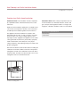
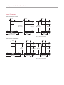
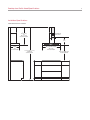
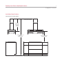
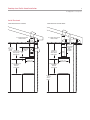
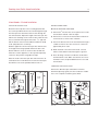
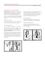
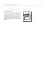
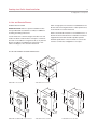
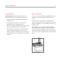
INSTALLATION GUIDE
Cooktop Low-Profile Ventilation Hoods
Contents
Important Note
Wolf Cooktop Low-Profile Ventilation Hoods . . . . . . . . 3
To ensure the safe and efficient use of Wolf equipment,
please take note of the following types of highlighted
information throughout this guide:
Cooktop Low-Profile Hood Specifications . . . . . . . . . . 4
Cooktop Low-Profile Hood Installation . . . . . . . . . . . . 8
Service Information . . . . . . . . . . . . . . . . . . . . . . . . . . . 18
Features and specifications are subject to change at any time
without notice. Visit wolfappliance.com/specs for the most
up-to-date information.
IMPORTANT NOTE: Throughout this guide, dimensions in
parentheses are millimeters unless otherwise specified.
IMPORTANT NOTE highlights information that is especially
important.
CAUTION signals a situation where minor injury or product
damage may occur if instructions are not followed.
WARNING states a hazard that may cause serious injury or
death if precautions are not followed.
Wolf Cooktop Low-Profile Ventilation Hoods
3
wolfappliance.com/specs
Cooktop Low-Profile Hood Installation
IMPORTANT NOTE: This installation must be completed
by a qualified installer or Wolf authorized service center
technician.
Read this entire installation guide prior to installation and
save for the local inspector’s reference. The homeowner
should keep this installation guide for future reference.
IMPORTANT NOTE: Wolf cooktop low-profile hoods are
recommended for use with Wolf induction, electric and
gas cooktops and integrated modules. For ranges and
rangetops, a Wolf pro ventilation hood is recommended.
Wolf Cooktop Low-Profile Hood
This appliance must be installed in accordance with
National Electrical Codes, as well as all state, municipal
and local codes. The correct voltage, frequency and
amperage must be supplied to the appliance from a dedicated, grounded circuit which is protected by a properly
sized circuit breaker or time delay fuse. The proper
voltage, frequency, and amperage ratings are listed on the
product rating plate.
Record the model and serial numbers before installing the
ventilation hood. Both numbers are listed on the product
rating plate, located on the underside of the hood, above
the grease filter. The filter must be removed to access the
rating plate. Refer to the illustration below.
RATING PLATE
Location of rating plate.
Model Number
Serial Number
Cooktop Low-Profile Hood Specifications
4
Overall Dimensions
LOW-PROFILE WALL HOODS
9 7/8"
10 7/8"
10 7/8"
(251)
(276)
(276)
5 7/8" (149)
7 7/8" (200)
TO
18 3/8" (467)
25 1/2" (648)
29 1/8" (740)
TO
31" (788)
TO
TO
20 1/8" (511)
411/2" (1054)
20 1/8" (511)
48 3/4" (1238)
3 1/8" (79)
30" (762), 36" (914) AND
45" (1143) WIDTHS
3 1/8" (79)
17 3/4"
17 3/4"
(451)
(451)
RECIRCULATING APPLICATION
LOW-PROFILE ISLAND HOOD
11 3/4"
9 7/8"
(298)
(251)
9 7/8"
(251)
2 3/8" (60)
4 3/4" (121)
TO
14" (356)
14" (356)
28 3/8" (721)
TO
30 3/4" (781)
TO
40" (1016)
TO
22 7/8" (581)
22 7/8" (581)
40" (1016)
3 1/8" (79)
42" (1067)
21 5/8" (549)
3 1/8" (79)
21 5/8" (549)
RECIRCULATING APPLICATION
Cooktop Low-Profile Hood Specifications
5
wolfappliance.com/specs
Installation Considerations
Electrical Requirements
Wolf cooktop low-profile hoods are recommended for
use with Wolf induction, electric and gas cooktops and
integrated modules. These hoods have a telescopic flue
that allows you to reach a ceiling height of 8' (2.4 m) to
9' (2.7 m) with a finished look.
Wolf cooktop low-profile ventilation hoods require a
separate, grounded 120 V AC, 60 Hz power supply. The
service should have its own 15 amp circuit breaker.
IMPORTANT NOTE: Wolf recommends that the bottom
of the ventilation hood be installed 24" (610) to 30" (762)
above the countertop.
Low-profile wall and island hoods are available with an
internal blower. Wall hood models CTEWH36 and
CTEWH45 will require an in-line or remote blower
assembly, available through your authorized Wolf dealer.
For local dealer information, visit the find a showroom
section of our website, wolfappliance.com.
The blower will vary in size and is dictated by the cooking
unit, the volume of air that needs to be moved and the
length of the duct run. Refer to ventilation recommendations in the Wolf design guide. These hoods have an 6"
(152) round duct with vertical discharge.
IMPORTANT NOTE: Use only a Wolf blower with the
cooktop low-profile hood.
BACKSPLASH
Optional stainless steel backsplashes are available in
widths to match all cooktop low-profile hoods through
your authorized Wolf dealer. For local dealer information,
visit the find a showroom section of our website,
wolfappliance.com.
Locate the electrical supply within the shaded area shown
in the illustration for your specific model on the following
pages.
IMPORTANT NOTE: You must follow all National Electrical
Code regulations. In addition, be aware of local codes and
ordinances when installing your service.
Cooktop Low-Profile Hood Specifications
6
Installation Specifications
LOW-PROFILE WALL HOODS
291/8" (740)
TO
411/2" (1054)
HEIGHT OF HOOD
E
LOCATION OF
ELECTRICAL
5"
(127)
15"
(381)
17 3/4"
(451)
DEPTH OF HOOD
30" (762), 36" (914) OR
45" (1143)
8' (2.4 m) TO 9' (2.7 m)
FLOOR TO
CEILING HEIGHT
WIDTH OF HOOD
24" (610) TO 30" (762)
TO COUNTERTOP
Cooktop Low-Profile Hood Specifications
7
wolfappliance.com/specs
Installation Specifications
LOW-PROFILE ISLAND HOODS
LOCATION OF ELECTRICAL
THROUGH TOP OF HOOD
28 1/4" (718)
TO
411/2" (1054)
HEIGHT
OF HOOD
21 5/8" (549)
DEPTH OF HOOD
42" (1067)
WIDTH OF HOOD
8' (2.4 m) TO 9' (2.7 m)
FLOOR TO
CEILING HEIGHT
24" (610) TO 30" (762)
TO COUNTERTOP
Cooktop Low-Profile Hood Installation
Ducting Options
Wolf cooktop low-profile hoods may be used in a ducted
or recirculating installation. For greatest efficiency, the
ducted installation is recommended.
DUCTED INSTALLATION
In a ducted installation, the hood aspirates the kitchen air
saturated with fumes and odors, passes it through the
grease filter and expels it to the outside through ductwork.
For this installation, a ventilation hood with an internal,
in-line or remote blower can be used. The in-line blower is
located in ductwork between the hood and the outside.
The remote blower can be mounted on the roof or, for wall
hoods, an exterior wall. Wolf in-line and remote blowers
are available through your authorized Wolf dealer.
RECIRCULATING INSTALLATION
IMPORTANT NOTE: Only low-profile hoods with an internal
blower can be used in a recirculating installation.
In a recirculating installation, the hood aspirates the
kitchen air saturated with fumes and odors, purifies it
through the grease filter and charcoal filter and returns
clean air into the room. A recirculation kit available through
your authorized Wolf dealer is required. For local dealer
information, visit the find a showroom section of our
website, wolfappliance.com.
8
Install Ductwork
To reduce the risk of fire, use only metal ductwork.
IMPORTANT NOTE: Unless used in a recirculating installation, ventilation hoods must exhaust to the outdoors.
A 6" (152) round duct is recommended for cooktop lowprofile hoods. Use only rigid metal ductwork, do not use
flex ducting. Consult a qualified HVAC engineer for
specific ducting applications.
Decide where the ductwork will run between the wall hood
and the outside. A straight, short duct run will allow the
hood to perform most efficiently. Limit the number of
elbows and transitions. The duct run should be no longer
than 50' (15 m). There is a possibility of noise issues, if a
remote blower is used with a short duct run.
Wolf recommends installing a backdraft damper in all
installations. A backdraft damper is included with the
hood. It is built into the transition from the hood to the
duct run.
Unless you are using a remote blower, a roof or wall cap
must be installed. Connect ductwork to the cap and work
back towards the hood. Use duct sealing tape to seal
joints between ductwork sections.
Local building codes may require the use of make-up air.
Consult your local HVAC professional for specific requirements in your area.
Cooktop Low-Profile Hood Installation
9
wolfappliance.com/specs
Install Ductwork
LOW-PROFILE WALL HOODS
LOW-PROFILE ISLAND HOOD
DUCTWORK INSTALLATION
THROUGH ROOF
DUCTWORK INSTALLATION
THROUGH ROOF
10 7/8"
(276)
8' (2.4 m)
TO 9' (2.7 m)
CEILING
HEIGHT
29 1/8" (740)
TO 411/2" (1054)
TELESCOPING
HOOD HEIGHT
DUCTWORK
INSTALLATION
THROUGH
WALL
1
20 /8"
(511)
28 3/8" (721)
TO 40" (1016)
TELESCOPING
HOOD HEIGHT
DUCTWORK
INSTALLATION
THROUGH
EAVE—
INTERNAL
BLOWER
9 7/8"
(251)
3 1/8" (79)
17 3/4" (451)
HOOD DEPTH
21 5/8" (549)
HOOD DEPTH
24" (610) TO 30" (762)
24" (610) TO 30" (762)
BOTTOM OF
HOOD TO
COUNTERTOP
BOTTOM OF
HOOD TO
COUNTERTOP
8' (2.4 m)
9' (2.7 m)
CEILING
HEIGHT
Cooktop Low-Profile Hood Installation
10
Wall Hoods—Ducted Installation
Locate the electrical supply through the wall within the
shaded area shown in the illustration on page 6. Install
ductwork as outlined on pages 8–9.
Mount the bottom panel to the hood. Attach with the four
screws provided on the hinge side of the panel.
IMPORTANT NOTE: If a backsplash is to be used, it should
be installed prior to mounting the wall hood. Secure the
hood mounting brackets to the wall studs prior to
installing the backsplash. Refer to installation instructions
provided with the backsplash.
Hang the hood on the bracket as shown in illus 2. Adjust
the horizontal position moving the hood to the right or left
so that it is properly aligned. When adjustment has been
completed, without removing the hood, mark the four
additional holes to be drilled in the wall. Remove the hood
and drill four 5/16" diameter holes and fit the screw
anchors provided. Mount the hood to the wall using the
screws provided.
Mount the plate of the electrical system fixing it with three
screws as shown in illus 3 below.
ATTACH TELESCOPIC FLUE
MOUNT HOOD TO WALL
IMPORTANT NOTE: Wolf recommends that the bottom
of the ventilation hood be installed 24" (610) to 30" (762)
above the countertop.
Draw a vertical line on the wall indicating the centerline of
the hood. Mark the first two holes to be drilled in the wall.
Position according to dimensions shown in illus 1 below.
Drill two 5/16" diameter holes and fit the screw anchors
provided. Attach the metal bracket to the wall using the
screws provided. Use the two cut-out triangles on the
bracket to position it exactly along the vertical axis of the
hood.
Assemble the three support brackets for the telescopic
flue as shown in illus 4. The width of the bracket assembly
can be adjusted. With screws and anchors provided,
attach the bracket assembly to the ceiling so that it is
positioned along the axis with the hood.
ANCHORS
SCREWS
BRACKET
5 1/16"
(129)
Illus 3.
13 3/8"
(340)
CENTER
OF HOOD
Illus 1.
Illus 2.
Illus 4.
Cooktop Low-Profile Hood Installation
11
wolfappliance.com/specs
Wall Hoods—Ducted Installation
Fit 6" (152) flexible metal ducting (not provided) to the air
vent of the hood and seal with duct tape. Refer to illus 5
below.
For exhaust hoods, turn the upper flue over so that the air
exhaust grid is in the lower section.
IN-LINE OR REMOTE BLOWER WIRING
Blower connection at the hood:
1) Run Romex® wire from the in-line or remote blower to
the hood’s electrical box marked “motor connection”.
2) Remove the cover from the electrical box and remove
one knockout as shown in illus 7 below.
WIRING CONNECTIONS
Electrical connection at the hood:
1) Run Romex® wire from the service panel to the hood’s
electrical box marked “120 V AC input”.
2) Remove the cover from the electrical box and remove
one knockout as shown in illus 6.
3) Secure the Romex® wire to the electrical box through a
conduit connector. Use wire connectors or wire nuts
approved by UL or C/UL.
4) Make electrical connections at the hood. Connect
white to white, black to black and green to ground.
5) Place all wiring connections inside the electrical box
and reinstall the cover. Make sure all wires are secure
and that no wires are pinched between the cover and
electrical box.
3) Secure the Romex® wire to the electrical box through a
conduit connector. Use wire connectors or wire nuts
approved by UL or C/UL.
4) Make electrical connections at the hood. Connect
white to red, black to black and green to ground.
5) Place all wiring connections inside the electrical box
and reinstall the cover. Make sure all wires are secure
and that no wires are pinched between the cover and
electrical box.
IMPORTANT NOTE: Refer to installation instructions
provided with the in-line or remote blower assembly for
additional mounting and wiring instructions.
ATTACH FLUE EXTENSION
Insert the flue extensions, setting them on the hood.
Extend the upper flue to the ceiling and secure with two
screws as shown in illus 8.
WIRING
BOX
FLEXIBLE
DUCTING
Illus 5.
SCREWS
WIRING
BOX
Illus 6.
Illus 7.
Illus 8.
Cooktop Low-Profile Hood Installation
12
Wall Hoods—Recirculating Installation
INTERNAL BLOWER MODELS
WIRING CONNECTIONS
IMPORTANT NOTE: A recirculation kit is required for this
installation. The kit is available through your authorized
Wolf dealer. For local dealer information, visit the find a
showroom section of our website, wolfappliance.com.
Follow the same instructions for wiring connections as
outlined for ducted installations on page 11.
Locate the electrical supply through the wall within the
shaded area shown in the illustration on page 6. Install
ductwork as outlined on pages 8–9.
MOUNT HOOD TO WALL
Follow the same instructions for mounting the hood to the
wall as outlined for ducted installations on page 10.
INSTALL CHARCOAL FILTER
First remove the grease filter(s). To access the filter(s),
gently press up on the front edge of the bottom panel and
allow it to rotate downward. Push the handle outward and
pull the grease filter(s) downward to remove. Then install
the charcoal filter by inserting the two filter clips in the
slots and turning the filter towards the inside of the hood.
Reinstall the grease filter(s) using the reverse procedure.
Refer to illus 11 below.
ATTACH TELESCOPIC FLUE
Assemble the three support brackets for the telescopic
flue as shown in illus 4 on page 10. The width of the
bracket assembly can be adjusted. With screws and
anchors provided, attach the bracket assembly to the
ceiling so that it is positioned along the axis with the hood.
Mount the flange on the hood to correspond with the air
outlet point shown in illus 9 below.
Fit 5" (127) flexible metal ducting (not provided) to the
air baffle of the hood and seal with duct tape. Attach the
air baffle to the upper flue with four screws as shown in
illus 10. Connect the other end of the flexible ducting to
the flange.
SCREWS
FLEXIBLE
DUCTING
Illus 9.
Illus 10.
CHARCOAL
FILTER
GREASE
FILTER
Illus 11.
Cooktop Low-Profile Hood Installation
13
wolfappliance.com/specs
Island Hoods—Ducted Installation
Locate the electrical supply through the wall within the
shaded area shown in the illustration on page 7. Install
ductwork as outlined on pages 8–9.
Mount the bottom panel to the hood. Attach with the four
screws provided on the hinge side of the panel. Refer to
illus 12 below.
MOUNT HOOD TO CEILING
Using the drilling template, drill holes for attaching the
mounting bracket to the ceiling on the vertical side of your
hood. The center line of the mounting bracket is in line
with the center of the control panel.
IMPORTANT NOTE: Placement of the mounting bracket is
critical for proper alignment of the hood with the cooktop.
Attach the mounting bracket to the ceiling using the
screws and anchors provided. Refer to illus 13 below. The
position of the bracket determines the final position of the
hood. The side with the slot corresponds to the side
opposite the controls.
Assemble the plate of the electrical system fixing it with
two screws and washers as shown in illus 14.
HINGE
BOTTOM PANEL
5 15/16"
Illus 12.
ELECTRICAL
PLATE
(151)
5 15/16"
(151)
SLOT
Illus 13.
Illus. 14
Cooktop Low-Profile Hood Installation
14
Island Hoods—Ducted Installation
ATTACH TELESCOPIC FLUE
WIRING CONNECTIONS
Attach the telescopic flue to the mounting bracket with
four screws provided. Run the air evacuation pipe through
the telescopic flue and run the Romex® wire through the
hole in the bracket. Adjust the height of the telescopic flue
with the four retaining screws. Refer to illus 15 below. Take
into account that the height of the hood is 3 1/8" (79) and
that the bottom of the hood should be installed 24" (610)
to 30" (762) above the countertop.
Electrical connection at the hood:
Slide the upper flue onto the telescopic flue with the slots
of the upper flue facing upwards. Attach the flue to the
bracket with two screws as shown in illus 16. Slide the
lower flue over the upper flue, to the top and temporarily
secure it in this position using adhesive tape.
Raise the hood to the telescopic flue and connect the air
outlet duct to the hood. Attach the hood to the telescopic
flue with the four screws provided. Refer to illus 17.
1) Run Romex® wire from the service panel to the hood’s
electrical box marked “120 V AC input”.
2) Remove the cover from the electrical box and remove
one knockout as shown in illus 18 below.
3) Secure the Romex® wire to the electrical box through a
conduit connector. Use wire connectors or wire nuts
approved by UL or C/UL.
4) Make electrical connections at the hood. Connect
white to white, black to black and green to ground.
5) Place all wiring connections inside the electrical box
and reinstall the cover. Make sure all wires are secure
and that no wires are pinched between the cover and
electrical box.
COMPLETE THE INSTALLATION
Remove the adhesive tape and slide the lower flue
downward, placing it gently onto the hood base. Installation is now complete. Install the grease filters.
ELECTRICAL
CABLE
UPPER
FLUE
WIRING
BOX
RETAINING
SCREW
Illus 15.
SCREWS
Illus 16.
Illus 17.
Illus 18.
Cooktop Low-Profile Hood Installation
15
wolfappliance.com/specs
Island Hoods—Recirculating Installation
IMPORTANT NOTE: A recirculation kit is required for this
installation. The kit is available through your authorized
Wolf dealer. For local dealer information, visit the find a
showroom section of our website, wolfappliance.com.
Attach the reduction to the air venting opening of the hood
by pressing slightly. Refer to illus 21 below. Raise the
hood to the telescopic flue and connect the air outlet duct
to the hood. Attach the hood to the telescopic flue with
the four screws provided as shown in illus 22.
Locate the electrical supply through the ceiling and inside
the area of the flue, above the mounting bracket and right
of center.
WIRING CONNECTIONS
MOUNT HOOD TO CEILING
Follow the same instructions for wiring connections as
outlined for ducted installations on the previous page.
Follow the same instructions for mounting the hood to the
ceiling as outlined for ducted installations on page 13.
COMPLETE THE INSTALLATION
ATTACH TELESCOPIC FLUE
Insert the air baffle into the structure as shown in illus 19.
Remove the adhesive tape and slide the lower flue
downward, placing it gently onto the hood base. Installation is now complete.
Through the opening, fit the flange to the baffle. Turn the
flange to secure it in place. Fit 5" (127) flexible metal
ducting (not provided) to the flange and seal with duct
tape. Refer to illus 20 below.
REDUCTION
Slide the upper flue onto the telescopic flue with the slots
of the upper flue facing upwards. Attach the flue to the
bracket with two screws as shown in illus 16 on the
previous page. Slide the lower flue over the upper flue, to
the top and temporarily secure it in this position using
adhesive tape.
SCREWS
Illus 21.
FLANGE
AIR BAFFLE
Illus 19.
FLEXIBLE
DUCTING
Illus 20.
Illus 22.
Cooktop Low-Profile Hood Installation
16
Island Hoods—Recirculating Installation
INSTALL CHARCOAL FILTER
First remove the grease filters. To access the filters, gently
press up on the front edge of the bottom panel and allow
it to rotate downward. Push the handle outward and pull
the grease filters downward to remove. Then install the
charcoal filter by inserting the two filter clips in the slots
and turning the filter towards the inside of the hood.
Reinstall the grease filters using the reverse procedure.
Refer to illus 23.
CHARCOAL
FILTER
GREASE
FILTER
Illus 23.
Cooktop Low-Profile Hood Installation
17
wolfappliance.com/specs
In-Line and Remote Blowers
Allow enough space for transitions needed between the
blower and connecting ductwork. For best performance,
locate transitions nearest the blower.
BLOWER INSTALLATION
IMPORTANT NOTE: Refer to specific installation instructions provided with each blower assembly for additional
mounting and wiring instructions.
Refer to the illustrations below for overall dimensions of
Wolf in-line and remote blowers. Installation instructions
shipped with each Wolf ventilation product provide
detailed specifications. These instructions can also be
found on our website, wolfappliance.com/specs.
Locate the blower so that the length of the duct run and
number of elbows and transitions are kept to a minimum.
The duct run should be no longer than 50' (15 m). Remote
blowers should be located between wall studs or roof
rafters. Avoid pipes, wires and other ductwork.
IN-LINE AND REMOTE BLOWER DIMENSIONS
24 7/8"
(632)
24 3/8"
(619)
18"
11 3/4"
(457)
(298)
12"
(305)
18 1/2"
(470)
4 1/2"
(114)
8"
(203)
211/2"
22"
12 1/4"
(546)
18"
(559)
(457)
(311)
600 CFM in-line blower.
1100 CFM in-line blower.
18" (457)
20 3/4"
28 1/4"
(718)
10"
(254)
29 1/2"
(527)
(749)
10" (254)
DIAMETER
DIAMETER
14 3/4"
15 1/2"
24 1/2"
29 1/2"
(375)
(254)
29 1/2"
(749)
10" (254)
(394)
21" (533)
10"
(749)
10" (254)
DIAMETER
14 3/4"
29 1/2"
(375)
(749)
(622)
10 1/8"
14"
10 3/8"
(257)
(356)
4 3/4"
24 3/4"
(121)
(629)
600 CFM and 900 CFM remote blower.
(264)
22"
(559)
1200 CFM remote blower.
7 1/4"
25"
7 1/4"
(184)
(635)
(184)
1500 CFM remote blower.
Service Information
18
Troubleshooting
Service Information
IMPORTANT NOTE: If the ventilation hood does not
operate properly, follow these troubleshooting steps:
If service is necessary, maintain the quality built into your
ventilation hood by calling a Wolf authorized service
center.
• Verify that electrical power is being supplied to the
ventilation hood.
• Check electrical connections to ensure that the
installation has been completed correctly.
• Refer to the troubleshooting guide in the Wolf cooktop
low-profile ventilation hoods use & care guide.
• If the ventilation hood still does not operate properly,
contact a Wolf authorized service center. Do not
attempt to repair the ventilation hood yourself. Wolf is
not responsible for service required to correct a faulty
installation.
To obtain the name and number of a Wolf authorized
service center, check the contact & support section of our
website, wolfappliance.com or call Wolf customer service
at 800-332-9513.
When calling for service, you will need the model and
serial numbers of the ventilation hood. This information is
found on the product rating plate, located on the underside of the hood, above the grease filter. The filter must be
removed to access the rating plate. Refer to the illustration
below.
RATING PLATE
Location of rating plate.
The information and images in this guide are the copyright property of Wolf Appliance, Inc. Neither this guide nor any information or images contained herein
may be copied or used in whole or in part without the express written permission of Wolf Appliance, Inc. ©Wolf Appliance, Inc. all rights reserved.
Wolf, Wolf & Design, Wolf Gourmet, W & Design and the color red as applied to knobs are registered trademarks and service marks of Wolf Appliance, Inc.
Sub-Zero, Sub-Zero & Design, Dual Refrigeration, Constant Care and The Living Kitchen are registered trademarks and service marks of Sub-Zero, Inc.
(collectively, the “Company Marks.”) All other trademarks or registered trademarks are property of their respective owners in the United States and other countries.
WOLF APPLIANCE, INC.
P. O. BOX 44848 MADISON, WI 53744
816999 REV-A
8/ 2010
WOLFAPPLIANCE.COM
800.332.9513