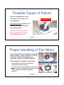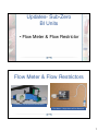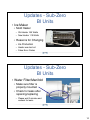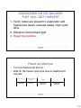
1
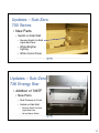
2010 Service Training
• Updates – Sub-Zero & Wolf
• New Products – Wolf & Sub-Zero
Liability Claims
• Important we receive part(s) back related to any potential liability claim
with damage to a customer’s home or if you think there is a possibility
for damages
•
Leaking water, food loss, wine loss, injury, etc…
• Even if you are unsure the customer will file a claim, or if customer
doesn’t mention anything but you notice there is damage, we need the
part(s) returned
• Contact Michelle Disch at [email protected], or via
Customer Service Line at 800-222-7820 x 7871, or via fax at 608-2046303 for a return label.
1
Liability Claims
• When you return part(s), please be sure you label properly
•
Tape label onto part(s) to include
•
Name of customer
•
Model and serial number
•
Date of the loss or service
•
Include copy of service invoice / NARD
• EXEPTION TO THE RULE:
If customer insists on keeping part(s) in their possession, be sure to have them
sign the service invoice stating they have retained the part(s) and keep that
signed copy on file. It is very important to have this clear record to show there is
no doubt the part(s) was/were left with customer.
Sub-Zero Updates
• LokRing
• BI Units
• Service Control Boards
• Crisper Fan Motors
• Flow Meter & Restrictor
• Dispenser Connection
2
Sub-Zero Updates
• BI Units Cont’d
• Air Flow
• Ice Maker
• Water Filter
• 700 Series – Integrated Units
• 736 Energy Star Units
• SKU Reductions
Updates- Sub-Zero
LokRing
• The use of LokRing is an acceptable alternative for
sealed system repairs.
• Contact LokRing direct to find suppliers of their products
@ www.lokringusa.com or 863-733-9013.
• We are not distributing any of the tools, accessories or
supplies.
• Please contact your Regional Service Manager with
questions.
• Contact LokRing for Refrigerant Recovery Bags
3
Updates - Sub-Zero
BI Units
• Service Control Boards
BI Units - Service Control Boards
• Model Configuration no longer uses the model codes when configuring
the service control boards.
• You will now toggle through code numbers.
Note: Production units still use model codes.
4
Updates - Sub-Zero
BI Units
• Crisper Drawer Fan Motors
Damaged Observed on Impeller
Rub mark on inner
wall of casing
• Shaft was loose from the
base of impeller yoke.
• 3 of 4 welding joints were
found broken on the yoke.
Cracks
The broken welding joints causes
the shaft to move and makes the
impeller wobble during rotation.
5
Possible Cause of Failure
• Believed damaged was due to
handling and installation of fan
into application.
Do not handle the
fan motor this way.
• 1kg force pressure applied on the
impeller can cause damage to
shaft welding joints.
• Please do not touch impeller
during unpacking of fan and
during assembly process.
Proper Handling of Fan Motor
• The Crisper Service Fan Motor is provided
w/the housing. There should be no need
to remove it from the housing by a
technician unless to carefully inspect it.
• If the customer complaint is noisy fans
•
Isolate which fans are noisy by Manual
Component Activation Mode
•
“If” the crisper fans are the source of the noise,
carefully inspect the Impeller Assembly for weld
cracks, replace Fan/Motor Assembly if
defective
Handle impeller from sides for inspection
6
Updates- Sub-Zero
BI Units
• Flow Meter & Flow Restrictor
Flow Meter & Flow Restrictors
Flow Meter – Dual Valve w/Flow Restrictor
Flow Meter – Single Valve w/Flow Restrictor
7
Flow Meter & Flow Restrictors
• Single Water Valve
• Flow Meter
• Water Valve
• Located behind
bracket
• Flow Restrictor
Updates- Sub-Zero
BI Units
• Dispenser Connections
8
Dispenser Connections
• Dispenser Control
Panel not functioning
• Make sure connection on
ribbon cable to Control
Panel is plugged in all the
way.
Updates – Sub-Zero
BI Units
• Air Flow
• Reverse Air Flow
• Evaporator Location
• Elimination of Crisper Fans
• Baffle
• Evaporator Cover
• Diverter
•
Must be in place to prevent
freezing in crispers
9
Updates - Sub-Zero
BI Units
• Ice Maker
• Mold Heater
• Old Heater 165 Watts
• New Heater 110 Watts
• Reasons for Changing
• Ice Production
• Heater was too hot
• False Error Codes
Updates - Sub-Zero
BI Units
• Water Filter/Manifold
• Make sure filter is
properly mounted
• Check for leaks after
repairing/replacing
• Please wait 2 minutes and
recheck for leaks
10
Updates – Sub-Zero
700 Series
• New Parts
• Switch on Side Wall
• Sensing Switch for Both
Lights and Fans
• Whiter/Brighter
Lighting
• White Control Panel
Updates – Sub-Zero
736 Energy Star
• Addition of 736TF
• New Parts
• Dual Closures in Front
• Switch on Side Wall
•
Sensing Switch for Both
Lights and Fans
•
No Ice Maker Switch
11
Updates – Sub-Zero & Wolf
SKU Reductions
•
All Sub-Zero framed built-in models, but framed accessories will be made available
to convert overlay models to framed models.
•
All Sub-Zero/Wolf curved handled models and related sales accessories
•
All Sub-Zero/Wolf carbon and platinum models and related sales accessories
•
All Sub-Zero integrated tall non-ice maker models
•
All Sub-Zero solid door wine storage models and related sales accessories
•
All Sub-Zero free-standing 424 wine storage models except for 424FS/TH-RH
•
All 427 and 427R sales accessory panels with locks except for 80” panels with
tubular handles and a 4” toekick
•
All Wolf ventilation models with rails
•
Two LP and Natural gas rangetops with Frenchtop
Wolf Updates
• Broiler Pan & Full Extension Oven
Rack
• E-Series Oven Tubular Handle
• 18” Broiler Pan
• Baking Sheet
• Control Board Logic
12
Wolf Updates
• Pro Series
• Burner Flame Quality
• Surface Igniters
• Integrated Module – IM15/S
• Intermittent Flames
Wolf Updates
• Broiler Pan
• Old
• New
• Standard in all units
• Full Extension Oven Rack
(DF & WO)
• One standard in all units
• DF s/n: 17184981
• WO s/n: 16104403
13
Wall Oven Updates
• E-Series Wall Oven
• Tubular Handle
Wolf Updates
• New 18” Broiler Pan
• Baking Sheet used
in 30” Oven
14
Dual Fuel Temperature Selection Change
• Changes made to programming of
Dual Fuel Control
•
Once cooking mode selected “- -” will appear in
selector knob
•
Customer then rotates knob to right or left
•
Display will then show predetermined temperature for
mode
•
Customer chooses predetermined temperature or
selects desired temperature
•
This allows for two step on feature
Tone will sound to signify cooking mode has begun
•
Dual Fuel Temperature Selection Change
• Changes made to programming of Dual Fuel Control
Serial number breaks for this change:
•
•
DF30 - 17159076
•
DF36 – 17159778
•
DF48 – 17159800
•
DF60 – 17159878
This change will also occur when new control boards are replaced on units with serial
numbers above 16000000. The boards with the new programming are:
•
•
DF30 – 807048
•
DF36 – 807049
•
DF48 – 807050
•
DF60 – 807051
15
Wolf Updates
• Range
• Burner Flame Quality
• Purpose: Instructions explain the
procedure for installing air diverters
and new burner rings on a Wolf Pro
Series Gas Range to improve flame
quality.
Wolf Updates
• Surface Igniters
• Black Ring Location
• Inconsistency during ignition
and missed spark on surface
burners
• Use pliers or flat bladed
screwdriver to push black ring
down
• Do Not push down to far as this
could cause further spark
issues
16
Wolf Updates
• Integrated Module
Replacement #75
• IM15/S (Natural Gas Only)
• Symptom: Intermittent flames
at ports of inner burner ring
when at lowest setting
• Solution: Install new valve
orifice bypass screw stamped
#75
Current Bypass
New Products - Wolf
• Cooktop Hoods
• Low-Profile Wall
• Low-Profile Island
• Drawer Microwaves
• MWD24 & MWD30
• Outdoor Grills
• OG
17
New Products - Wolf
Cooktop Low-Profile Wall Hood
• Recommended for
use with Wolf…
• Induction Cooktops
• Electric Cooktops
• Gas Cooktops
New Products - Wolf
Cooktop Low-Profile Island Hood
• Recommended for
use with Wolf…
• Induction Cooktops
• Electric Cooktops
• Gas Cooktops
18
Cooktop Low-Profile Hoods
• Classic stainless steel with black
glass front panel
• Multi-speed blowers
• Wall hood only
• Available in three widths
• Wall hood only
Cooktop Low-Profile Wall Hood
• Wall Hood Models
• CTEWH30I
• CTEWH36
• CTEWH36I
• CTEWH45
• CTEWH45I
19
Cooktop Low-Profile Island Hood
• Island Hood Model
• CTEIH42
Cooktop Low-Profile Hoods
• Wall Hood Blower Options
• 500 CFM internal blower
• Included with CTEWH30I,
CTEWH36I and CTEWH45I
• 600 or 1100 CFM in-line blower
for CTEWH36 or CTEWH45
• 600, 900, 1200 or 1500 CFM
remote blower for CTEWH36 or
CTEWH45
20
Cooktop Low-Profile Hoods
• Island Hood Blower
• 500 CFM internal blower
Cooktop Low-Profile Wall Hood
• Accessories – Wall Hood
• 30” high classic stainless steel
wall shield in 30” and 36”
widths
• Recirculation kit for non-ducted
installations
• Replacement charcoal filters
21
Cooktop Low-Profile Island Hood
• Accessories – Island Hood
• Recirculation kit for non-ducted
installations
• Replacement charcoal filters
Cooktop Low-Profile Hoods
• Features
• Heavy-duty stainless steel with
classic stainless finish
• Telescopic flue fits 8’ to 9’ ceilings
• Front-mounted electronic controls
• Sealed halogen lighting with three
settings
• Internal, in-line and remote blower
options for wall hoods
22
Cooktop Low-Profile Hoods
• Features cont’d
• Internal blowers – Island Hood
includes internal blower
• Used in a non-ducted application using
an accessory charcoal filter
• Heat Sentry
• Automatically turns unit on when heat is
sensed
• Automatically adjusts blower speed
Cooktop Low-Profile Hoods
• Features cont’d
• Delay-off mode
• Automatically turns unit off
• Stainless steel filter cover with dishwasher
safe aluminum mesh filter
• Filter clean indicator
• Indicates when filter needs cleaning
• Transition with backdraft damper included
23
Cooktop Low-Profile Hoods
• Filter and Blower
Access
New Products - Wolf
Drawer Microwave Oven
MWD24-2U/S
MWD30-2F/S
MWD30-2U/S
24
Drawer Microwave Oven - Features
•
•
•
•
•
•
Classic stainless steel finish
Trim style matches E-Series Oven
Can be installed standard or flush
950 Watts
1 cubic ft. interior space
Accommodate 9” x 13” pan
Drawer Microwave Oven - Features
• 11 programmable power levels
• Sensor cooking
• Warm feature to keep food warm
for 30 minutes
• Interactive display
• Window in drawer to view inside
• One touch key pad to open and
close drawer
• Control panel can be deactivated
or locked
25
Drawer Microwave Oven – Drawer Gear Removal
(This procedure requires a 14" or greater phillips
screwdriver)
1. Disengage any power going to the unit.
2. Open the drawer and keep it open.
3. Remove the top cover and right side cabinet.
4. Disconnect wiring to Auto Drawer Gear.
5. Remove bottom screw below Auto Drawer Gear
6. Remove the (4) screws holding the auto drawer gear to
the bottom cavity angle.
7. Disengage (pull) Auto Drawer Gear from rack gear and
slide to the right (toward the rear), then turn motor 90°
and slip out along rear of drawer.
8. Then tilt Auto Gear Motor 20°to extract the assembly
out. The Auto Drawer Gear is now free.
New Products - Wolf
Outdoor Grills
26
Outdoor Grill
LIMITED LIFETIME WARRANTY
• For the life of the product, Wolf Appliance will repair
or replace any outdoor gas grill body or hood that
rusts through due to defective material or
workmanship.
• Labor to remove and replace defective parts is not
covered.
• Wolf Appliance recommends that a Wolf Authorized
Service Center is used to perform such service.
Outdoor Grill
• OG30 & OG30-LP
• Rotisserie
• Natural or LP gas
• OG36 & OG36-LP
• Rotisserie & Sear burner
• Natural or LP gas
27
Outdoor Grill
• OG42 & OG42-LP
• Rotisserie & Sear burner
• Natural or LP gas
• OG54 & OG54-LP
• Rotisserie & Sear burner
• Natural or LP gas
•
Built-In Only
• OG Units can be converted
but expensive
• Outsourced from Twin
Eagles
Outdoor Grill
• Key Features
• Halogen lighting
• Briquette system for even
heating
• Hot surface ignition
• Illuminated controls
• Warming shelf
• Spring assisted hood
• Thermometer
28
• Key features
Outdoor Grill
Sear section
•
25,000 BTU’s
•
Rotisserie
•
Multiple position
•
14,000 BTU’s OG30& OG36
•
Two 14,000 BTU End to End OG54
•
•
16,0000 BTU’s OG42
•
Stainless steel grates
•
Stainless steel
U-Tube burners
•
25,000 BTU’s
Outdoor Grill
• Electric Requirements
•
Plug the power cord from the
transformer into a properly grounded
GFCI 120 V AC outlet. The outlet must
be located within 6' (1.8 m) of the
transformer.
•
The rotisserie motor requires a GFCI
120 V AC electrical supply. The 9' (2.7
m) power cord on the motor is
equipped with a 3-prong grounded
plug for protection against shock
hazard.
29
Outdoor Grill
• Carts
• 30”, 36” & 42” shipped
as separate units
Cart & Accessories Options
30
Outdoor Grill
Accessories
• Side Burner
• Shipped as Separate Unit
• Comes with Cover
Outdoor Grill
Accessories
Stand Alone Option
• Burner Module (BM)
• Easy Access for Side Mount
or Stand Alone
31
Outdoor Grill
New Product – Sub-Zero
• Undercounter Ice Maker
• UC-15I
• UC-15IP
• UC-15IO
• UC-15IPO
32
Undercounter Icemaker
• Outsourced from Manitowoc
• Improved performance and
features
• Same integrated panel size
and door hinge as 315I
•
Door opening can be reversed
• 2 to 3 times higher ice
production – lbs. per day
• Time to fill bin reduced by 50%
Undercounter Icemaker
• Features
• Water filter
• Bin light
• Electronic control
•
Power button
•
Delay start 2/4/8 hours
•
“Clean” button
•
Replace filter light
33
Undercounter Icemaker
• Integrated polycarbonate ice
scoop on door
• Anti-microbial plastic
• Stainless steel wraper
• Side panels not removable
• New improved ice shape
• Improved serviceability
Undercounter Icemaker
• 16 cube evaporator vs.
8 cube evaporator
• Approximately 2 times
more production in 24Hr
period
34
Undercounter Icemaker
• Tin Coated Evaporator Plate
• New Cleaner P/N 7013400
and Sanitizer P/N 7013401
• Made by Manitowoc
• Recommend cleaning
every 6 months
• DO NOT use Scotsman
cleaner P/N 19034306
•
Cleaner will eat through tin coating on
evaporator
Undercounter Icemaker
Damage to the ice machine evaporator
caused by incorrect chemical usage is not
covered by the warranty.
Use ONLY Sub-Zero approved ice
machine cleaner (7013400) and sanitizer
(7013401).
35
Undercounter Icemaker
• New Thermostat
Mounting
• Accessible by removing
kick plate
Undercounter Icemaker - Rear View
Refrigeration Line Set
Water Pump
Drain Pump
Water Inlet Supply
Vent Tube for Drain
Pump
Compressor
36
UC15I - Objectives
•
Installation
•
Door Swing Reversal
•
Removal of parts for Cleaning and Sanitation
•
Top 8 Operational Checks
•
Sequence of operation
•
Electrical troubleshooting
•
Refrigeration
•
Diagnosing an ice machine that will not run
•
Diagnosing an ice machine that will not freeze
•
Diagnosing an ice machine that will not harvest
Model/Serial Number Location
Model Serial Tag
inside and back of unit.
37
Installation
Installation
• Water Filter is shipped in the bin
and requires it to be manually
installed in the front of the ice
machine.
• The ice machine can operate with
or without the water filter installed,
because the filter head has a built
in bypass.
38
Installation
• The location must be free of airborne and other contaminants.
• Do Not place unit within 18” of a trash compactor or trash/recycling container.
• The air temperature must be at least 50°F, but must not exceed 100°F for
models UC15I & UC15IP.
• The air temperature must be at least 50°F, but must not exceed 110°F for
models UC15IO & UC15IPO.
• The location must not be near heat-generating equipment.
• The location must not obstruct air flow through the condenser (airflow is in and
out the front of the ice machine).
• The location must allow enough clearance for water, drain and electrical
connections at the rear of the ice machine.
Installation
• Do not connect the ice machine to a
hot water supply.
• If water pressure exceeds the
maximum recommended pressure
(80 psi), obtain a water pressure
regulator from your local plumbing
contractor.
39
Door Swing Reversal
1. Remove four screws that
secure door hinges to ice
machine
•
Note: Make sure to remove shim
located between cabinet and
bottom hinge and transfer to
other side
2. & 3. Remove hinges from
door
Door Swing Reversal
4. Transfer hinges and reattach. Upper hinge will
need to become lower hinge
and visa versa.
5. Remove the top of ice
machine cover by removing
screws along back of unit.
40
Door Swing Reversal
6.
Remove four screws from the
front top rail.
7.
Pivot top rail end for end to
expose the two left hand top
hinge screw holes and expose
left hand hinge mounting holes.
8.
Remove two screws from bottom
trim plate and slide to cover right
hand hinge holes.
9.
Install door
Cleaning/Sanitizing
41
Undercounter Icemaker
• New Cleaner P/N 7013400
and Sanitizer P/N 7013401
• Made by Manitowoc
• Recommend cleaning
every 6 months
• DO NOT use Scotsman
cleaner P/N 19034306
•
Cleaner will eat through tin coating on
evaporator
Water shutters
• Top Cover will need to be removed
• Grasp one end of the water shutter
and lift up.
• Pivot water shutter and disengage
remaining end.
• To re-install into ice machine, grasp
one end of the water shutters, install
one end, pivot the opposite end and
pull down into position.
• Make sure tabs are secure in
grooves
42
Ice chute
• Grab protruding spray hole on
one end and lift up and
remove.
• To re-install ice chute, grasp
protruding spray hole and
position over Water
Distribution Assembly. Make
sure rear supports are over
spray bar, and front edge is
inside of water trough.
Spray Bar
•
Grasp one end of the spray bar, lift up and
remove from seat formed in evaporator
bucket.
•
Remove clamp on water inlet tubing by
grasping both ears on clip and separating.
•
Apply food grade lubricant to ease reassembly of spray bar components when
necessary.
•
To re-install spray bar, position water inlet
tubing on inlet ports, and squeeze clips until
tight.
•
Reposition assembly on water trough seat.
43
Sump Drain Overflow Tube
• Remove clamp.
• Pull down to remove overflow
tube and tubing as an
assembly. The sump trough
water will drain into the bin.
• Remove overflow tube from
vinyl tubing by pulling.
Water Trough and Pump
•
Depress tabs on right and left side of the
water trough.
•
Allow front of water trough to drop as you
pull forward to disengage the rear pins.
•
Grasp pump and pull straight down until
water pump disengages and electrical
connector is visible.
•
Disconnect the electrical connector
•
Remove the water pump from ice
machine.
•
Remove clamp from hose to remove from
pump.
44
Undercounter Icemaker
Damage to the ice machine evaporator
caused by incorrect chemical usage is not
covered by the warranty.
Use ONLY Sub-Zero approved ice
machine cleaner (7013400) and sanitizer
(7013401).
Undercounter Icemaker
• Interior Components
• Inside of unit is food storage (ice
being food)
• Wear clean rubber gloves to
protect from spreading
contamination
45
Top 8 Operational Checks
1. Water Inlet Valve
Water Inlet Valve
• The water inlet valve
energizes in the harvest
cycle.
• The water level will rise and
flow out the overflow tube
and down the drain. Verify
the overflow tube is in place
in the water trough.
• The water level is not
adjustable
46
Top 8 Operational Checks
1. Water Inlet Valve
2. Bin Thermostat Adjustment
Bin Thermostat Adjustment
• The bin thermostat stops the ice machine when the bin is full.
• Turn the thermostat to the left to decrease the level of ice in
bin or to the right to increase the level of ice in bin.
• Factory Setting = fully counter-clockwise and one click
clockwise.
47
Top 8 Operational Checks
1. Water Inlet Valve
2. Bin Thermostat Adjustment
3. Power Button (Green)
Power Button (Green)
SUB-ZERO Control Panel
• Pressing the “Power” button once will energize the ice
machine and green Power light. Pressing the “Power” button
a second time will de-energize the ice machine.
48
Top 8 Operational Checks
1.
2.
3.
4.
Water Inlet Valve
Bin Thermostat Adjustment
Power Button (Green)
Automatic Ice Making Light (Blue)
Automatic Ice Making Light (Blue)
SUB-ZERO Control Panel
• This light is (on) energized when the ice machine is the ice making
position.
• The light is off when the ice machine is in the clean
SM50 Control Panel
49
Top 8 Operational Checks
1.
2.
3.
4.
5.
Water Inlet Valve
Bin Thermostat Adjustment
Power Button (Green)
Automatic Ice Making Light (Blue)
Delay Start
Delay Start
Pressing the “Delay Start” button will initiate a delay cycle. The ice machine will not run
until the delay time expires.
•
Pressing the button once will energize the 2 hour light and initiate a two hour delay period.
•
Pressing the button a second time will energize the 4 hour light and initiate a four hour delay
period.
•
Pressing the button a third time will energize the 8 hour light and initiate an eight hour delay
period.
•
Pressing the button a fourth time will cancel the delay cycle.
50
Top 8 Operational Checks
1.
2.
3.
4.
5.
6.
Water Inlet Valve
Bin Thermostat Adjustment
Power Button (Green)
Automatic Ice Making Light (Blue)
Delay Start
Clean (Green)
Clean (Green)
•
Pressing the “Clean” button will initiate a clean cycle and de-activate the “Ice”
light.
•
The water system will enter a fill/flush mode for approximately (90) seconds.
•
After which the clean light will flash to indicate time to add ice machine cleaner or
sanitizer.
SM50 Control Panel
51
Undercounter Icemaker
Damage to the ice machine evaporator
caused by incorrect chemical usage is not
covered by the warranty.
Use ONLY Sub-Zero approved ice
machine cleaner (7013400) and sanitizer
(7013401).
Top 8 Operational Checks
1. Water Inlet Valve
2. Bin Thermostat Adjustment
3. Power Button (Green)
4. Automatic Ice Making Light (Blue)
5. Delay Start
6. Clean (Green)
7. Replace Filter (Red)
52
Replace Filter (Red)
SUB-ZERO Control Panel
• When the ice machine completes 8000 freeze/harvest cycles the light
will energize to indicate the filter needs replacement.
• Depressing the “Clean” button for 6 seconds will reset the counter
and de-energize the light.
Top 8 Operational Checks
1. Water Inlet Valve
2. Bin Thermostat Adjustment
3. Power Button (Green)
4. Automatic Ice Making Light (Blue)
5. Delay Start
6. Clean (Green)
7. Replace Filter (Red)
8. Safety Timers
53
Safety Timers
The control board has the following
non-adjustable safety timers:
•
Initial cycle is 5 minutes longer than subsequent cycles.
•
The ice machine is locked into the freeze cycle for 10 minutes (15 minutes initial cycle)
before a harvest cycle can be initiated.
•
The maximum freeze time is 120 minutes at which time the control board automatically
initiates a harvest cycle (step 4 of sequence of operation).
•
The maximum harvest time is 5 minutes at which time the control board automatically
starts a freeze cycle.
Sequence of Operation
54
Sequence of Operation
Initial Start Pushing Power Button
55
Initial Start Up
#1
Initial Start
up
175
Seconds
Energized Parts
•Water Pump
•Water Inlet Valve
•Harvest Solenoid
Energized Parts
•Water Pump
•Water Inlet Valve
•Harvest Solenoid
56
Refrigeration System Start Up
#2
Initial Start
up
Refrigeration
System Start Up
175
Seconds
5 Seconds
Energized Parts
•Water Pump
•Water Inlet Valve
•Hot Gas Solenoid
•Compressor
•Fan Motor
Energized Parts
•Water Pump
•Water Inlet Valve
•Hot Gas Solenoid
•Compressor
•Fan Motor
57
Freeze
#3
Initial Start
up
175
Seconds
Refrigeration
System Start Up
5 Seconds
Freeze
Automatically
determined*
Energized Parts
•Water Pump
•Compressor
•Fan Motor
The maximum freeze time
is 120 minutes at which
time the control board
automatically initiates a
harvest cycle
*Liquid line thermistor determines the length of the freeze and
harvest cycles. Liquid line temperature also determines fan motor
operation during the harvest cycle.
Energized Parts
•Water Pump
•Compressor
•Fan Motor
58
Refrigeration Tubing (Freeze)
DRIER
Harvest
Energized Parts
#4
Initial Start
up
175
Seconds
Refrigeration
System Start Up
5 Seconds
Freeze
Harvest
Automatically
determined*
Automatically
determined*
•Compressor
•Hot Gas Solenoid
•Water Inlet Valve
•Fan Motor
During the last minute of the freeze cycle the control board took another set of temperature
readings and calculated how long it should take to harvest 16 cubes of ice.
59
Energized Parts
•Compressor
•Hot Gas Solenoid
•Water Inlet Valve
•Fan Motor
Refrigeration Tubing (Harvest)
DRIER
60
Sequence of Operation
#1
Initial Start
up
175
Seconds
#2
#3
#4
Freeze
Harvest
Automatically
determined*
Automatically
determined*
Refrigeration
System Start Up
5 Seconds
Bin Level
Thermostat
Closed
Bin Level Thermostat Closed
•Return to Freeze Cycle
**No ice touching Bin Level Probe.
Sequence of Operation
#1
Initial Start
up
175
Seconds
#2
#3
#4
Freeze
Harvest
Automatically
determined*
Automatically
determined*
Refrigeration
System Start Up
5 Seconds
Bin Level
Thermostat
Open
(Full Bin)
Bin Level Thermostat
Open/Full Bin
•Automatic Shut Off
**Ice touching Bin Level Probe.
61
Sequence of Operation
#2
#1
Initial Start
up
175
Seconds
Refrigeration
System Start Up
5 Seconds
#3
#4
Freeze
Harvest
Automatically
determined*
Automatically
determined*
Bin Level
Thermostat
Open
(Recloses)
Bin Level Thermostat
Recloses
•Initial Start Up
**No Ice touching Bin Level Probe.
Refrigeration Operation Pressures
•
•
•
•
Critically charged refrigeration system
5.6 oz
R-134A / CAP TUBE
Use short stubby gauge hoses
62
DIAGNOSING AN ICE MACHINE
THAT WILL NOT RUN
1. Verify primary voltage is supplied to ice
machine.
DIAGNOSING AN ICE MACHINE
THAT WILL NOT RUN
• Verify primary voltage
is supplied to ice
machine.
63
DIAGNOSING AN ICE MACHINE
THAT WILL NOT RUN
1. Verify primary voltage is supplied to ice
machine.
2. Verify control board fuse is OK.
Verify control board fuse is OK.
64
DIAGNOSING AN ICE MACHINE
THAT WILL NOT RUN
1. Verify primary voltage is supplied to ice
machine.
2. Verify control board fuse is OK.
3. Verify the transformer is supplying power to the
control board.
Verify the transformer is supplying power to
the control board.
•
If the interior light functions or the red control board light is energized the transformer is
OK.
•
If the transformer is supplying power to the control board and the red control board light
will not energize, replace the control board.
65
DIAGNOSING AN ICE MACHINE
THAT WILL NOT RUN
1. Verify primary voltage is supplied to ice
machine.
2. Verify control board fuse is OK.
3. Verify the transformer is supplying power to the
control board.
4. Verify the “Power” botton functions properly.
Verify the “Power” button functions properly.
•
If the red control board light is energized and depressing the “Power” button (on
the user display) does not energize the green “Power” light,
•
check the interconnecting wire for proper connection and 17VDC – 15VDC,
•
if correct voltage present, then replace the interface board.
66
DIAGNOSING AN ICE MACHINE
THAT WILL NOT RUN
1. Verify primary voltage is supplied to ice
machine.
2. Verify control board fuse is OK.
3. Verify the transformer is supplying power to the
control board.
4. Verify the “Power” button functions properly.
5. Verify the bin thermostat functions properly.
Verify the bin thermostat functions properly
• Bin Thermostat is functioning
correctly if –
• When three ice cubes are placed
on the thermostat tube for 5
minutes, the ice machine stops.
• The ice machine should restart 5
minutes after the ice cubes are
removed.
• If the ice machine stops before the bin is
full or runs after the bin is full, ambient
temperatures are probably high or low
and the bin thermostat can be adjusted.
67
DIAGNOSING AN ICE MACHINE
THAT WILL NOT RUN
1. Verify primary voltage is supplied to ice machine.
2. Verify control board fuse is OK.
3. Verify the transformer is supplying power to the control
board.
4. Verify the “Power” button functions properly.
5. Verify the bin thermostat functions properly.
6. Check control board light to see if ice machine shutdown on
over temperature limit (control board light will flash rapidly).
Observe control board light:
•
Steady light indicates thermistor operation is normal.
•
Slow flash indicates a thermistor problem (open or disconnected). Verify liquid line
thermistor is connected to control board and is securely attached to liquid line and insulated.
Refer to Resistance chart and Ohm thermistor.
•
Rapid flash indicates liquid line temperature exceeded 170°F (refer to “Discharge Pressure
High Checklist”).
•
If unable to determine cause, refer to Resistance chart and Ohm thermistor.
68
Thermister Diagnostics
Verify that the thermistor resistance is
accurate and corresponds to the high
and low temperature ranges.
1. Disconnect the thermistor at the control
board. Connect the ohmmeter to the isolated
thermistor wire leads.
2. Using a temperature meter capable of
taking readings on curved copper lines,
attach the temperature probe to the liquid line
next to the thermistor aluminum block.
Discharge Pressure High Checklist
•
Improper Installation
• Refer to "Installation and Visual
Inspection Checklist”
•
Restricted Condenser Air Flow
• High inlet air temperature
• Condenser discharge air re-circulation
• Dirty condenser fins
• Defective fan motor
• Improper Refrigerant Charge
• Overcharged
• Non-condensable in system
• Wrong type of refrigerant
•
Other
•
Non-Sub-Zero components in
system
•
High side refrigerant
lines/component restricted (before
mid-condenser)
69
DIAGNOSING AN ICE MACHINE
THAT WILL NOT RUN
1.
Verify primary voltage is supplied to ice machine.
2.
Verify control board fuse is OK.
3.
Verify the transformer is supplying power to the control board.
4.
Verify the “Power” button functions properly.
5.
Verify the bin thermostat functions properly.
6.
Check control board light to see if ice machine shutdown on over temperature limit
(control board light will flash rapidly).
7.
Replace the control board.
• Be sure Steps 1-6 were followed thoroughly. Intermittent problems are not usually
related to the control board.
ICE MACHINE RUNS AND
NO ICE IS PRODUCED
1.
No Water to ice machine
•
2.
Correct water supply (Cold water only?)
Incorrect incoming water pressure
•
3.
Water pressure must be 20-80 psi (Clogged water filter?)
Spray nozzle is blocked with mineral buildup
•
4.
Clean and sanitize the ice machine
Ambient temperature is too high or low
•
5.
Ambient temperature must be between 50°- 110°F. (Dirty Condenser?)
Thermistor Disconnected or Open
•
Refer to Thermistor Diagnostics
70
Thermistor Diagnostics
Verify that the thermistor resistance is
accurate and corresponds to the high
and low temperature ranges.
1. Disconnect the thermistor at the control
board. Connect the ohmmeter to the isolated
thermistor wire leads.
2. Using a temperature meter capable of
taking readings on curved copper lines,
attach the temperature probe to the liquid line
next to the thermistor aluminum block.
DIAGNOSING AN ICE MACHINE
THAT WILL NOT HARVEST
1. Verify cubes are present in evaporator and
freeze time doesn’t exceed freeze chart cycle
time.
71
Verify cubes and freeze time doesn’t exceed
freeze chart cycle time.
• Initial freeze cycle after
resetting “Power” button
will be 5 minutes longer
than chart time (refer to
“Sequence of Operation”)
• Verify control board is not
set for additional freeze
time to fill out the ice
cubes, see “Cube
Weight Adjustment”
Cube Weight Adjustment
The cube weight can be increased from the factory
setting by adjusting the finish time.
Adjust in 1-minute increments and allow the ice machine to run several freeze/harvest cycles, and then inspect
the ice cubes. If a heavier cube weight is desired add another minute of freeze time and repeat the process.
1.
2.
Press and hold the power button.
Press and release the clean button once for each additional minute of freeze cycle time desired. Five minutes
is the maximum additional freeze time that can be added. Pressing the clean button 6 times will reset the
finishing time to zero additional minutes.
72
DIAGNOSING AN ICE MACHINE
THAT WILL NOT HARVEST
1. Verify cubes are present in evaporator and
freeze time doesn’t exceed freeze chart cycle
time.
2. Observe control board light
Observe control board light:
•
Steady light indicates thermistor operation is normal.
•
Slow flash indicates a thermistor problem (open or disconnected). Verify liquid
line thermistor is connected to control board, securely attached to liquid line and
insulated. Refer to Resistance chart and Ohm thermistor.
•
Rapid flash indicates liquid line temperature exceeded 170°F (refer to
“Discharge Pressure High Checklist”). If unable to determine cause, refer to
Resistance chart and Ohm thermistor.
73
DIAGNOSING AN ICE MACHINE
THAT WILL NOT HARVEST
1. Verify cubes are present in evaporator and
freeze time doesn’t exceed freeze chart cycle
time.
2. Observe control board light
3. Reset ice machine.
Reset Ice Machine
• Turn ice machine off and on.
• Wait for the freeze cycle time plus an additional 5
minutes.
Initial Start up
175 Seconds
Refrigeration System
Start Up
5 Seconds
Freeze
Automatically
determined*
Harvest
Automatically
determined*
74
DIAGNOSING AN ICE MACHINE
THAT WILL NOT HARVEST
1. Verify cubes are present in evaporator and
freeze time doesn’t exceed freeze chart cycle
time.
2. Observe control board light
3. Reset ice machine.
4. Verify the water inlet valve is energized during
the entire harvest cycle and water flow is
normal.
Water inlet Valve
• Although the hot gas valve is
energized, the ice machine will
not consistently harvest if the
water inlet valve does not
energize or has low water flow.
75
DIAGNOSING AN ICE MACHINE
THAT WILL NOT HARVEST
1. Verify cubes are present in evaporator and freeze
time doesn’t exceed freeze chart cycle time.
2. Observe control board light
3. Reset ice machine.
4. Verify the water inlet valve is energized during the
entire harvest cycle and water flow is normal.
5. Check for power at the hot gas solenoid
Check for power at
the hot gas valve
• Power is present – replace
coil/valve.
• No power at hot gas valve –
check for power at circuit board
connector, replace control board
if no power is present
76
New Product – Sub-Zero
• Column Units
• Existing features/
minor upgrades
• Energy Star
New Product – Sub-Zero
• Models
• IC-27R
Integrated Column
27” All Refrigerator
• IC-27F
Integrated Column
27” All Freezer
77
New Product – Sub-Zero
• Both over 16 cu ft of storage
• Bright interior lighting
• Soft-Close storage drawers
with dedicated lighting
• Crisper drawer
• User reference card (like BI Units)
• Dual install w/ any other
integrated product
• Note: Columns Units are 81” tall vs.
80” tall for all other tall integrated
products
New Product – Sub-Zero
• Control Panel
• Top of compartment
78
New Product – Sub-Zero
• Interior Features
• Similar to Built-In Units
New Product – Sub-Zero
• Interior Features
• New Door Shelves
• Top & Lower non-interchangeable
• Bottom Door Shelve
79
New Product – Sub-Zero
• Door Hinges
New Product – Sub-Zero
• Serial Tag
• Located on Handle
side of unit under top
rail
80
New Product – Sub-Zero
• Interior IC-27R
• Evaporator Fan
• Control Board
• Evaporator Access
• Cabinet Thermistor
• Foam Block must be in
place for proper sensing
New Product – Sub-Zero
• Interior IC-27F
• Access
• Ice maker
• Evaporator Fan
• Evaporator Assembly
81
New Product – Sub-Zero
• Unit Tray Assembly
• Remove 4 screws from
condenser
• Remove top trim piece
• Remove two screws
securing unit tray and
carefully pull out
New Product – Sub-Zero
• Unit Tray Assembly
• Condenser Fan/Motor
82
Kits 813806 (4 Burner) & 813807 (2 Burner)
Burner Flame Quality Kit
Purpose: These instructions explain the procedure for installing air diverters and new burner rings
on a Wolf Pro Series Gas Range to improve flame quality.
BOTH GAS AND ELECTRICAL SUPPLY MUST BE TURNED OFF TO THE UNIT BEFORE ATTEMPTING THIS
PROCEDURE.
BE CAREFUL WHEN HANDLING SHEET METAL PARTS. THERE MAY BE SHARP EDGES.
Kit Contents:
Kit #
813806 813807
Part Description
Qty
Qty
Air - Burner Diverter
4
2
Burner - Flame Quality Cap
4
2
Directions:
NOTE: Before installing kit, verify gas pressure is at the
recommended level (See chart below). Low pressure can
cause flame issues that will not be remedied by this kit.
Picture 1 Burner Screws
Gas Type
Pressure
Required
Natural
LP
Maximum 14” WC Maximum 14” WC
Minimum 7” WC Minimum 11” WC
Supply
Static Manifold
(No burners on)
Approximately
Supply Pressure
Approximately
Supply Pressure
Dynamic Manifold
(At least one burner on)
5” WC
± .5” WC
10” WC
± .5” WC
Picture 2 Diverter
1. Remove grates and black pressed steel tops from the
range.
2. Remove burner rings and caps from the burners.
3. Remove screws holding down the burners. (Picture 1)
4. Install the air diverters on each burner and reinstall
screws. (Picture 3)
Picture 3 Diverter Installed
5. Install burner rings and new burner caps. (Picture 4)
NEW
ORIGINAL
6. Install the press steel tops and grates.
7. Turn electricity and gas supplies back on and check the
unit for functionality.
EXTRA
HOLES
Picture 4 Burner Cap
Wolf Appliance, Inc.
800.332.9513
P.O. Box 44848
Madison, WI 53744
www.wolfappliance.com
813808 - Rev. A - 12 /23 / 2008
SERVICE BULLETIN
Black Ring Location on Wolf Pro-Series Surface Igniters
Purpose: We have received reports from the field of spark inconsistency during ignition and
missed spark on Pro-Series surface burners. It has been determined that black ring location can be
the determining factor. Please see the directions and diagram below showing the recommended
location for the black ring.
Ring Location:
Use a pliers or flat blade screwdriver to push the ring down on the igniter. (See Figure 1 for ring
position.)
NOTE: Do NOT push black ring down far enough to touch the simmer base; this will cause further
spark issues!
Black Ring
Simmer Base
~ 5/32” (4 mm)
Figure 1. Black Ring Location
15 June, 2009
Page 1 of 1
S E RV I C E B U L L E T I N
IM15/S and ICBIM15/S - Intermittent Flames at Low Setting (Natural Gas Only)
SYMPTOM:
Intermittent flames at ports of multi-function inner burner ring on models IM15/S and ICBIM15/S (natural gas only), when
unit is at lowest setting.
SOLUTION:
Change the natural gas multi-function valve orifice bypass screw to a longer bypass screw stamped “75” (See Figure 1).
NOTE: To acquire this orifice bypass screw you must contact Wolf Technical Assistance by phoning (800) 919 - 8324, or
(608) 271 - 2233, and referencing this memo.
Replacement Bypass Screw
Stamped “75”
Current Bypass Screw
Figure 1. Valve Bypass Screw Comparison
PROCEDURE:
1. Remove control knob.
2. Insert a small blade flat head screwdriver through opening in glass to extract and replace valve bypass screw. If
needed, use a needle nose pliers to grab and lift existing bypass screw after unthreading it with the screwdriver, and
to insert new bypass screw before tightening with screwdriver (See Figure 2 or 2A).
Glass Opening
OFF
Valve Bypass
Screw
Glass Opening
Valve Bypass
Screw
LOW
HIGH
MED
Figure 2. Valve Bypass Screw (Domestic)
10 / 14 / 2009
Figure 2A. Valve Bypass Screw (International)
Page 1 of 1