1
University of Pretoria etd – Combrinck, M (2006)
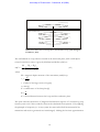
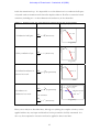
•
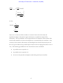
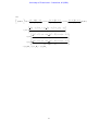
Thin, conductive sheet (S-layer)
•
Finite conductor in a resistive host rock (half space)
•
Finite conductor in a conductive host rock (half space).
2.3.1
TDEM central-loop response over a conductive half space
The quasi-static approximation of EM-field propagation in a half space can be described as
a diffusion process (Nabighian, 1979). When doing a TDEM survey the current in the
transmitter loop is switched off very abruptly, causing a sudden change in the associated
magnetic field (large ∂B/∂t). Following from Maxwell’s third equation the electric field (E)
associated with this sudden change in magnetic field will cause a current to flow in the
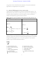
conductive half space ( j = σE ). This current will mimic the primary transmitter loop
geometry but will only exist in that form for a fraction of a second as it is not confined to a
specific path or circuit and has no source (battery) to maintain current flow. The induced
current will therefore immediately start to dissipate, generating a new magnetic field that
changes with time and consequently induce new currents in the half space. This behaviour
was discussed extensively by Nabighian (1979), leading to the smoke-ring concept of EM
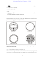
propagation in a homogeneous half space. In short, a number of EM induced currents
exist in the half space after the primary field is terminated and the maximum current
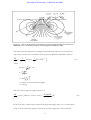
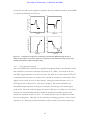
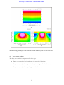
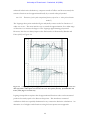
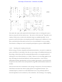
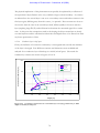
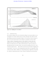
density retains a transmitter loop-like shape expanding with time. Contouring the electric
field at different points in time clearly show the maxima of the electric field (most
dominant currents) migrating outward and downward into the half space at an angle of
approximately 30°. Nabighian (1979) also introduced the mathematical alternative of a
single equivalent current filament that will produce, with a high degree of accuracy, the
same EM fields measured on the surface of the earth, as would the whole system of real
currents. This equivalent current filament moves outward and downward at an angle of
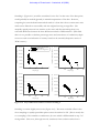
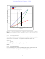
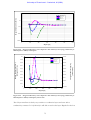
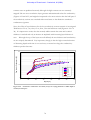
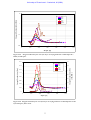
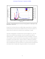
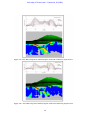
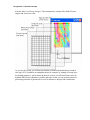
approximately 47°. A comparison of these two approaches is shown in figure 2.1. The
advantage of using the single equivalent current filament is the dramatic simplification in
mathematical description that allows the calculation of parameters such as velocity and
depth with time as well as relationships of these to half space conductivity.
7