1
User's Manual
xi
SENTOSAxi
LINE QUADRUPLER
LANCIAxi
xi
LINE DOUBLER
Safety Instructions • English
This symbol is intended to alert the user of important operating and maintenance
(servicing) instructions in the literature provided with the equipment.
This symbol is intended to alert the user of the presence of uninsulated
"dangerous voltage" within the product's enclosure that may present a risk of
electric shock.
Caution: To prevent the risk of shock, do not remove the cover (or
open the enclosure). There are no user-serviceable parts inside.
Refer servicing to qualified service personnel.
Caution
Read Instructions • Read and understand all safety and operating instructions
before using the equipment.
Retain Instructions • The Safety Instructions should be kept for future reference.
Follow Warnings • Follow all warnings and instructions marked on the equipment or
in the user information.
Avoid Attachments • Do not use (tools or) attachments that are not recommended
by the equipment manufacturer because they may be hazardous.
Warning
Power Sources • This equipment should be operated only from the power source
indicated on the product. This equipment is intended to be used with a main
power system with a grounded (neutral) conductor. The third (grounding) pin is
a safety feature, do not attempt to bypass or disable it.
Power Disconnection • To remove power from the equipment safely, remove all
power cords from the rear of the equipment, or the desktop power module (if
detachable), or from the power source receptacle (wall plug).
Power Cord Protection • Power cords should be routed so that they are not likely to
be stepped on or pinched by items placed upon or against them.
Servicing • Refer all servicing to qualified service personnel. Do not attempt to
service this equipment yourself because opening or removing covers may
expose you to dangerous voltage or other hazards.
Slots and Openings • If the equipment has slots or holes in the enclosure, these are
provided to prevent overheating of sensitive components inside. These
openings must never be blocked by other objects.
Lithium Battery • Danger of explosion if battery is incorrectly replaced. Replace
only with the same or equivalent type recommended by the manufacturer.
Dispose of used batteries according to the manufacturer's instructions.
Sicherheitsanleitungen • Deutsch
Dieses Symbol soll den Benutzer auf wichtige Anleitungen zur Bedienung und
Wartung (Instandhaltung) in der Dokumentation hinweisen, die im
Lieferumfang dieses Gerätes enthalten ist.
Dieses Symbol soll den Benutzer darauf aufmerksam machen, daß im Inneren
des Gehäuses dieses Produktes gefährliche Spannungen, die nicht isoliert
sind und die einen elektrischen Schock verursachen können, herrschen.
Achtung: Zur Vermeidung eines elektrischen Schocks bitte nicht
die Abdeckung entfernen (oder das Gehäuse öffnen). Im Inneren
des Gerätes sind keine Teile enthalten, die vom Benutzer
gewartet werden können. Eine Wartung sollte nur durch einen
qualifizierten technischen Service durchgeführt werden.
Achtung
Lesen der Anleitungen • Bevor Sie das Gerät zum ersten Mal verwenden, sollten
Sie alle Sicherheits-und Bedienungsanleitungen genau durchlesen und
verstehen.
Aufbewahren der Anleitungen • Die Sicherheitsanleitungen sollten aufbewahrt
werden, damit Sie später darauf zurückgreifen können.
Befolgen der Warnhinweise • Befolgen Sie alle Warnhinweise und Anleitungen
auf dem Gerät oder in der Benutzerdokumentation.
Keine Zusatzgeräte • Verwenden Sie keine (Werkzeuge oder) Zusatzgeräte, die
nicht ausdrücklich vom Hersteller empfohlen wurden, da diese eine
Gefahrenquelle darstellen können.
Vorsicht
Stromquellen • Dieses Gerät sollte nur über die auf dem Produkt angegebene
Stromquelle betrieben werden. Dieses Gerät wurde für eine Verwendung mit
einer Hauptstromleitung mit einem geerdeten (neutralen) Leiter konzipiert. Der
dritte Stift oder Kontakt ist für einen Erdschluß, und stellt eine
Sicherheitsfunktion dar und sollte nicht umgangen oder außer Betrieb gesetzt
werden.
Stromunterbrechung • Um das Gerät auf sichere Weise vom Netz zu trennen,
sollten Sie alle Netzkabeln aus der Rückseite des Gerätes oder aus dem
Desktop-Strommodul (falls dies möglich ist) oder aus der Wandsteckdose
ziehen.
Schutz des Netzkabels • Netzkabel sollten stets so verlegt werden, daß sie nicht
im Weg liegen und niemand darauf treten kann oder Objekte darauf- oder
unmittelbar dagegengestellt werden können.
Wartung • Alle Wartungsmaßnahmen sollten nur von qualifiziertem
Servicepersonal durchgeführt werden. Versuchen Sie in keinem Fall, dieses
Gerät selbst zu warten, da beim Öffnen oder Entfernen der Abdeckungen die
Gefahr eines elektrischen Schlags oder andere Gefahren bestehen.
Schlitze und Öffnungen • Wenn das Gerät Schlitze oder Löcher im Gehäuse
aufweist, dienen diese zur Vermeidung einer Überhitzung der empfindlichen
Teile im Inneren. Diese Öffnungen dürfen niemals von anderen Objekten
blockiert werden.
Litium-Batterie • Explosionsgefahr, falls die Batterie nicht richtig ersetzt wird.
Ersetzen Sie nur durch diegleiche oder einen vergleichbaren Batterietyp, der
auch vom Hersteller empfohlen wird. Entsorgung der verbrauchten Batterien
bitte gemäß den Herstelleranweisungen.
Consignes de Sécurité • FRANÇAIS
Ce symbole sert à avertir l’utilisateur que la documentation fournie avec le matériel
contient des instructions importantes concernant l’exploitation et la
maintenance (réparation).
Ce symbole sert à avertir l’utilisateur de la présence dans le boîtier de l’appareil de
« tensions dangereuses » non isolées posant des risques d’électrocution.
Attention : Afin d’éviter tout danger d’électrocution, ne pas enlever le
couvercle (ni ouvrir le boîtier). Aucun des éléments internes ne peut
être réparé par l’utilisateur. S’adresser à un technicien de
maintenance qualifié.
Attention
Lire les instructions• Prendre connaissance de toutes les consignes de sécurité et
d’exploitation avant d’utiliser le matériel.
Conserver les instructions• Ranger les consignes de sécurité afin de pouvoir les
consulter à l’avenir.
Respecter les avertissements • Observer tous les avertissements et consignes
marqués sur le matériel ou présentés dans la documentation utilisateur.
Eviter les pièces de fixation • Ne pas utiliser de pièces de fixation (ni d’outils) non
recommandés par le fabricant du matériel car cela risquerait de poser certains
dangers.
Avertissement
Alimentations• Ne faire fonctionner ce matériel qu’avec la source d’alimentation
indiquée sur l’appareil. Ce matériel doit être utilisé avec une alimentation
principale comportant un fil de terre (neutre). Le troisième contact (de mise à la
terre) constitue un dispositif de sécurité : n’essayez pas de la contourner ni de la
désactiver.
Déconnexion de l’alimentation• Pour mettre le matériel hors tension sans danger,
déconnectez tous les cordons d’alimentation de l’arrière de l’appareil ou du
module d’alimentation de bureau (s’il est amovible) ou encore de la prise secteur.
Protection du cordon d’alimentation • Acheminer les cordons d’alimentation de
manière à ce que personne ne risque de marcher dessus et à ce qu’ils ne soient
pas écrasés ou pincés par des objets.
Réparation-maintenance • Faire exécuter toutes les interventions de réparationmaintenance par un technicien qualifié. L’utilisateur ne doit pas essayer de
procéder lui-même à ces opérations car l’ouverture ou le retrait des couvercles
risquent de l’exposer à de hautes tensions et autres dangers.
Fentes et orifices • Si le boîtier de l’appareil comporte des fentes ou des orifices,
ceux-ci servent à empêcher les composants internes sensibles de surchauffer.
Ces ouvertures ne doivent jamais être bloquées par des objets.
Lithium Batterie • Il a danger d'explosion s'il y a remplacment incorrect de la batterie.
Remplacer uniquement avec une batterie du même type ou d'untype équivalent
recommandé par le constructeur. Disposer les batteries usagées conformément
aux instructions du fabricant.
Instrucciones de seguridad • Español
Este símbolo se utiliza para advertir al usuario sobre instrucciones importantes
de operación y mantenimiento (o cambio de partes) que se desean destacar
en el contenido de la documentación suministrada con los equipos.
Este símbolo se utiliza para advertir al usuario sobre la presencia de elementos
con "voltaje peligroso" sin protección aislante, que puedan encontrarse
dentro de la caja o alojamiento del producto, y que puedan representar
riesgo de electrocución.
Precaución: Para evitar riesgo de electrocución, no extraer la tapa
(ni abrir la caja). En el interior no hay partes a las que el usuario
deba acceder. Solicitar el servicio de personal técnico calificado.
Precaucion
Leer las instrucciones • leer y analizar todas las instrucciones de operación y
seguridad, antes de usar el equipo.
Conservar las instrucciones • conservar las Instrucciones de Seguridad para
futura consulta.
Obedecer las advertencias • todas las advertencias e instrucciones marcadas en
el equipo o en la documentación del usuario, deben ser obedecidas.
Evitar el uso de accesorios • no usar herramientas o accesorios que no sean
especificamente recomendados por el fabricante, ya que podrian implicar
riesgos.
Advertencia
Alimentación eléctrica • este equipo debe conectarse únicamente a la fuente/tipo
de alimentación eléctrica indicada en el mismo. La alimentación eléctrica de
este equipo debe provenir de un sistema de distribución general con conductor
neutro a tierra. La tercera pata (puesta a tierra) es una medida de seguridad,
no puentearia ni eliminaria.
Desconexión de alimentación eléctrica • para desconectar con seguridad la
acometida de alimentación eléctrica al equipo, desenchufar todos los cables
de alimentación en el panel trasero del equipo, o desenchufar el módulo de
alimentación (si fuera independiente), o desenchufar el cable del receptáculo
de la pared.
Protección del cables de alimentación • los cables de alimentación eléctrica se
deben instalar en lugares donde no sean pisados ni apretados por objetos que
se puedan apoyar sobre ellos.
Reparaciones/mantenimiento • solicitar siempre los servicios técnicos de personal
calificado. No intentar personalmente la reparación/mantenimiento de
esteequipo, ya que al abrir o extraer las tapas puede quedar expuesto a
voltajes peligrosos u otros riesgos.
Ranuras y aberturas • si el equipo posee ranuras u orificios en su caja/
alojamiento, es para evitar el sobrecalentamiento de componentes internos
sensibles. Esta aberturas nunca se deben obstruir con otros objetos.
Batería de litio • existe riesgo de explosión si esta batería se coloca en la posición
incorrecta. Cambiar esta batería únicamente con el mismo tipo (o su
equivalente) recomendado por el fabricante. Desachar las baterías usadas
siguiendo las instrucciones del fabricante.
Extron's Warranty
Extron Electronics warrants the product against defects in
materials for a period of two years and defect in workmanship for
a period of two years from the date of purchase. In the event of
malfunction during the warranty period attributable directly to
faulty workmanship and/or materials, Extron Electronics will, at
its option, repair or replace said products or components, to
whatever extent it shall deem necessary to restore said product
to proper operating condition, provided that it is returned within
the warranty period, with proof of purchase and description of
malfunction to:
Extron Electronics
1230 South Lewis Street
Anaheim, CA 92805, U.S.A.
This Limited Warranty does not apply if the fault has been
caused by misuse, improper handling care, electrical or
mechanical abuse, abnormal operating conditions, or any
modification to the product not authorized by Extron Electronics.
Before calling Extron, get the serial number of the unit in
question, a description of the problem and the name of the
person to contact in case there are any questions. This will
speed up the process. With this information in hand, call an
Extron Applications Engineer at (714) 491-1500 and ask for a
Return Authorization number (RA#).
Returned units must be insured, with shipping charges prepaid.
If not insured, you assume the risk of loss or damage during
shipment. Extron Electronics make no further warranties either
expressed or implied with respect to the product and its quality,
performance, merchantability, or fitness for any particular use. In
no event will Extron Electronics be liable for direct, indirect, or
consequential damages resulting from any defect in this product
even if Extron Electronics has been advised of such damage.
Please note that laws vary from state to state, and that some
provisions of this warranty may not apply to you.
Extron Electronics
1230 South Lewis Street
Anaheim, CA 92805
(714) 491-1500 FAX (714) 491-1517
U.S.A.
Extron Electronics, Europe
Beeldschermweg 6C
3821 AH Amersfoort
+31-33-453-4040 FAX +31-33-453-4050
The Netherlands
Extron Electronics, Asia
41B Kreta Ayer Road
Singapore 089003
+65-226-0015 FAX +65-226-0019
Singapore
Contents
xi LQ & Lanciaxi
xi LD ...................................... Chapter 1
Introduction to Sentosaxi
Introduction .......................................................................................... 1-1
About this Manual ......................................................................... 1-1
Features ....................................................................................... 1-2
Specifications ............................................................................... 1-3
Installation and Operation ................................................................... Chapter 2
Installing the Sentosaxi/Lanciaxi ......................................................................... 2-1
Rack Mounting ............................................................................. 2-1
Cabling ......................................................................................... 2-1
Connecting the Input and Output Cables .............................. 2-1
Connecting the RS-232 Cable .............................................. 2-2
Switch Settings ............................................................................. 2-3
DIP Switch Module ....................................................................... 2-4
Front and Rear Panels ................................................................. 2-5
Front Panel ............................................................................ 2-5
Rear Panel ............................................................................ 2-6
Operation ............................................................................................. 2-7
Application Diagrams ........................................................................... 2-7
Video Loop Back Application ............................................................... 2-9
RS-232/REMOTE Control ..................................................................... Chapter 3
RS-232 Control .................................................................................... 3-1
Host/Sentosaxi/Lanciaxi Communications .................................... 3-1
Using the Command/Response Table ......................................... 3-1
Command/Response Table .......................................................... 3-2
Error Responses .......................................................................... 3-3
Sentosaxi/Lanciaxi-Initiated Responses ....................................... 3-3
Sentosaxi/Lanciaxi Control Software ................................................... 3-3
Installing the Software .................................................................. 3-3
Using the Software ....................................................................... 3-4
Remote Contact Closure Operation .................................................... 3-5
Other Reference Material .................................................................. Appendix A
Accessories/Part Numbers ................................................................. A-1
Safety Instructions ...................................................... Inside Front Cover
Limited Warranty ......................................................... Inside Back Cover
Written and Printed in the USA
Sentosaxi Line Quadrupler
Lanciaxi Line Doubler
User’s Manual
68-254-01
Rev. C
89-05
Page i
Legend of Icons
The following icons may be used in this manual:
___ Important information – for example, an action or a step that must
be done before proceeding.
___ A Warning – possible damage could occur.
_ A Note, a Hint, or a Tip that may be helpful.
__ Possible Electrostatic Discharge (ESD) damage could result from
touching electronic components.
__ Additional information may be referenced in another section, or in
another document.
Page ii
Extron • SENTOSAxi LQ & LANCIAxi LD • User’s Manual
Extron’s SENTOSAxi & LANCIAxi
User’s Manual
1
Chapter One
xi & Lanciaxi
xi
Introduction to Sentosaxi
Introduction
Features
Specifications
Extron • SENTOSAxi LQ & LANCIAxi LD • User’s Manual
Introduction to the SENTOSAxi LQ & LANCIAxi LD
Introduction
About This Manual
This manual contains operation/configuration information for the
Sentosaxi Line Quadrupler (LQ) and Lanciaxi Line Doubler (LD).
xi LD Facts and Features
Sentosaxi
xi LQ and Lanciaxi
Extron’s Sentosaxi LQ and Lanciaxi LD are high resolution, digital
video devices which convert interlaced video into non-interlaced
video. The Sentosaxi LQ and Lanciaxi LD convert the two field
frame into a single non-interlaced frame consisting of 1,050 lines
(LQ) and 525 lines (LD) producing a brighter, higher resolution
picture. The additional lines provide more light output and make
the overall image brighter.
The Sentosaxi and Lanciaxi each have a high quality three-line
adaptive comb filter that eliminates most of the chroma noise
found in standard composite video signals. In addition, an internal
TBC (Time Base Corrector) actually cleans-up low quality videotape signal noise (common to VHS tape players) for a more stable
and sharper image. Motion mode compensation virtually
eliminates the “jaggies” commonly found on video line quadruplers
and line doublers so that the image is smoother.
The Sentosaxi LQ and Lanciaxi LD include an internal two input
switcher - one S-Video and one composite video input are front
panel selectable, remote selectable as well as auto-switchable.
With the use of a high quality quad-standard decoder the
Sentosaxi LQ and Lanciaxi LD are compatible with all international
video formats including NTSC 3.58, NTSC 4.43, PAL and SECAM.
Features
•
•
Page 1-1
xi LQ include the following.
Features unique to the Sentosaxi
Line quadrupler - Quadruples the resolution of standard video
from 525 lines at 15 kHz to 1050 non-interlaced lines at 63 kHz for
a clearer brighter output.
Demo-mode - Built-in “demo mode” allows a triple-split screen of
video, line doubled and line quadrupled video side by side.
Extron • SENTOSAxi LQ & LANCIAxi LD • User’s Manual
Introduction to the SENTOSAxi LQ & LANCIAxi LD
•
•
•
•
•
•
•
•
•
•
•
xi LD include the following.
Features unique to the Lanciaxi
Line doubler - Doubles the resolution of standard video from 525
interlaced lines at 15 kHz to 525 non-interlaced lines at 31.5 kHz for
a clearer, brighter output.
Demo-mode - Built-in “demo mode” allows split screen of video
and line doubled video side by side.
VGA mode - Conveniently converts video signals to 480 lines of
non-interlaced VGA. This VGA output allows you to plug directly
into digital display devices for RGBHV signal transmission.
Features of Sentosaxi and Lanciaxi include the following.
Quad-standard decoder - Sentosaxi and Lanciaxi are compatible
with all international video formats including NTSC 3.58, NTSC
4.43, PAL and SECAM.
Motion mode compensation - With motion mode compensation,
the Sentosaxi and Lanciaxi virtually eliminate the “jaggies” found in
line quadrupled or line doubled video.
Picture controls - Picture controls include color, hue (tint),
horizontal shift and contrast for each input. The Sentosaxi and
Lanciaxi will save picture controls for each of the two inputs.
RS-232 control - A rear panel RS-232 serial port provides access
for a third-party remote control system.
Input sync detection - In auto-switch mode the input with a signal
present is automatically selected, perfect for the video loop-back
feature of the System 8 and 10 PLUS switchers.
Universal compatibility - Outputs either RGsB, RGBS or RGBHV
signals at 31.5 kHz for the Lanciaxi and 63 kHz for the Sentosaxi.
Output sync polarity - Sync polarity can be adjusted through rear
panel DIP switches (positive or negative H&V) to allow for any
projector to recognize the Sentosaxi or Lanciaxi input versus a
standard VGA input and save different convergence, brightness
and contrast settings.
Rack mountable - The Sentosaxi and Lanciaxi fit into a 1U high,
1/2 rack width metal enclosure.
Extron • SENTOSAxi LQ & LANCIAxi LD • User’s Manual
Page 1-2
Introduction to the SENTOSAxi LQ & LANCIAxi LD
xi LD Specifications
Sentosaxi
xi LQ & Lanciaxi
Inputs
Video level .. 0.7 – 1 volt p-p
S-Video level (Y/C) .. Y = 0.7 volts p-p
.. C = 0.3 volts p-p (burst)
Connectors .. Video - female BNC
.. S-Video - female 4-pin mini-DIN
Impedance .. 75 ohms
Outputs
Video level .. 0.7 volts p-p
Sync level .. 4-5 volts p-p (TTL)
Sync polarity .. Composite – Negative
.. H&V – Positive or Negative
.. (DIP switch selectable)
Sync output frequency .. Lanciaxi
NTSC 3.58/4.43 .. 31.5 kHz horizontal
.. 60 Hz vertical
PAL/SECAM .. 31.25 kHz horizontal
.. 50 Hz vertical
NOTE: When Lanciaxi VGA mode is active, vertical frequency is
forced to 60 Hz with any video input.
Sync output frequency .. Sentosaxi
NTSC 3.58/4.43 .. 63 kHz horizontal
.. 60 Hz vertical
PAL/SECAM .. 62.5 kHz horizontal
.. 50 Hz vertical
DC offset .. 0.1 volt (max)
Connectors .. 5 female BNCs
Impedance .. 75 Ohms
General
Page 1-3
Remote control .. RS-232 and contact closure
Bandwidth .. 50 MHz (-3 dB)
MTBF .. 30,000 hours (demonstrated)
Storage temp .. -40 C to 70 C (-32 to 158 F)
Operating temp .. 0 C to +50 C (-32 to 122 F)
Humidity .. 10% to 90% non condensing
Vibration .. NSTA 1A in carton
Dimensions .. 1.75” H x 8.75” W x 9.5” D
.. 4.45 x 22.22 x 24.13 cm
Rack mountable .. Yes, 1U shelf (Part # 60-190-01)
Weight .. 5.0 lbs
.. 2.3 kg
Approvals .. UL, CE mark
Power supply .. 100-240 VAC, 50/60 Hz
.. Internal auto-switchable
Warranty .. Two Years, parts & Labor
Extron • SENTOSAxi LQ & LANCIAxi LD • User’s Manual
Extron’s SENTOSAxi LQ and LANCIAxi LD
User’s Manual
2
Chapter Two
Installation and Operation
Rack Mounting
Cabling
Switch Settings
DIP Switch Module
Front and Rear Panels
Operation
Applications
Extron • SENTOSAxi LQ & LANCIAxi LD • User’s Manual
Installation and Operation
xi
xi
Installing the Sentosaxi
xi/Lanciaxi
If rack mounting is required it should be done before cabling,
otherwise, skip to “Cabling” below.
Rack Mounting
The Sentosaxi/Lanciaxi can be rack mounted using one side of an
optional 19” 1U Universal Rack Shelf (Extron PN# 60-190-01).
To rack mount the Sentosaxi/Lanciaxi, do the following:
1. If feet were previously installed on the bottom of the case,
remove them.
2. Mount the Sentosaxi/Lanciaxi on the rack shelf as shown
below using two 4-40 x 1/8 screws in opposite (diagonal)
corners to secure the case to the shelf.
3. Upon completion of the rack mounting procedure, go to
“Cabling” below.
Cabling
The Sentosaxi/Lanciaxi is capable of switching between two
inputs, one composite and one S-Video. Therefore, one of each
video input type may be connected.
Connecting the Input/Output Cables
1. Connect the input devices to the Sentosaxi/Lanciaxi using the
appropriate cables as described below. Use the diagram on the
next page as a general guide.
A. If the input device to be connected has an S-Video output,
an S-Video cable will be used to connect it to the S-Video
input connector of the Sentosaxi/Lanciaxi.
B. If the input device to be connected has a composite video
output, a BNC cable will be used to connect it to the BNC
input of the Sentosaxi/Lanciaxi. The composite video output
from a VCR or Laser Disc Player will most likely require an
RCA to BNC adapter. An adapter of this type can generally
be purchased at a local electronics store.
Page 2-1
Extron • SENTOSAxi LQ & LANCIAxi LD • User’s Manual
Installation and Operation
2. The BNC output connectors of the Sentosaxi/Lanciaxi should
be connected to the display device using high resolution
coaxial cable such as Extron’s BNC-4 or BNC-5.
Connecting the RS-232 Cable
To connect the Sentosaxi/Lanciaxi to a computer, refer to the
picture below and connect the user supplied RS-232 cable from
the Host system/device serial port to the Sentosaxi/Lanciaxi
connector labeled RS-232.
___ When connecting to the RS-232 port, connect only pins 2, 3 and 5.
Pins 1, 4 and 6 - 9 must be left unconnected as they are reserved
for “Remote Contact Closure Operation” – see page 3-5.
PC
Computer
Extron • SENTOSAxi LQ & LANCIAxi LD • User’s Manual
Page 2-2
Installation and Operation
Switch Settings
The switches on the DIP switch module used in the
Sentosaxi/Lanciaxi are the “rocker” type (see end view
drawing, below-right). The primary difference between
the rocker type and the “slide” type (which could also
be used) is the action required to change the position
of the switch. To change the position of the rocker type
switch, press down against the desired end (enable or
disable) with a pointed object. To change the position
of the slide switch, a small screwdriver is used to push
(slide) the switch to the desired position (enable/on or
disable/off).
Set the DIP Switches, located on the rear panel of the
Sentosaxi/Lanciaxi, as required. The right side of the
switch module is the enable position. (See DIP switch
descriptions beginning at the bottom of this page.)
Sentosaxi Rear Panel
Lanciaxi Rear Panel
Select the desired sync type using the H/HV/SOG toggle switch
(located between the H/HV and V BNC connectors – see rear
panel drawings above). Switch positions are:
Top (H) = Horizontal sync on H/HV BNC, Vertical sync on V BNC
Center (HV) = Composite HV sync on H/HV BNC
Bottom (SOG) = Sync on Green BNC
xi and Lanciaxi
xi
DIP Switch Module (Sentosaxi
xi)
The function of each DIP switch follows. The switches on the DIP
Switch module are numbered 1 – 8 from top to bottom.
#1 – AUTO SW (Auto Switch Mode)
Disabled – Input selection is a manual operation through the
front panel input selection switch or through the
RS-232/Contact REMOTE connector.
Enabled – The input with video present will be selected
automatically. Input 2 has priority (If video is
present on both connectors, Input 2 will be
selected.)
Page 2-3
Extron • SENTOSAxi LQ & LANCIAxi LD • User’s Manual
Installation and Operation
#2 – SERR REM (Serration Pulse Removal)
Disabled – Serration pulses are passed along with the
vertical sync pulse.
Enabled – Serration pulses are removed from the output
vertical sync pulse.
#3 – SPLIT SCR (Sentosaxi = Tri-screen, Lanciaxi = split screen)
Disabled – Split screen is disabled.
Enabled – Split screen (Demo Mode) displays the selected
input interlaced video on the left side of the
screen. The remainder of the screen depends on
the model.
• Sentosaxi displays line quadrupled video in the
center of the screen and line doubled video on
the right side of the screen.
• Lanciaxi displays line doubled video on the
right half of the screen.
#4 – STILL (STILL Mode)
Disabled – Motion Compensation Mode – optimizes motion
video such as from VCRs, DVDs, Tuners, etc.
Enabled – Motionless video, such as text, will have
enhanced resolution for easier reading.
#5 – VGA (VGA Mode) Lanciaxi only, SPARE on Sentosaxi
Disabled – The output will have twice the number of input
horizontal lines per screen scan. For NTSC, the
number of horizontal lines per screen scan,
normally 262.5, will double to 525. For the PAL
system, the number of horizontal lines per screen
scan, normally 312.5, will double to 625 lines.
(This description assumes that SW#3, Split
Screen, is disabled).
Enabled – Active vertical resolution becomes 480 noninterlaced horizontal lines, regardless of the input.
#6 – H+ (Horizontal Sync Polarity Positive)
Disabled – The horizontal sync polarity will be negative.
Enabled – The horizontal sync polarity will be positive.
#7 – V+ (Vertical Sync Polarity Positive)
Disabled – The vertical sync polarity will be negative.
Enabled – The vertical sync polarity will be positive.
#8 – X MODE (Executive Mode)
Disabled – All front panel operations are enabled.
Enabled – Front panel picture controls (Color, Tint, Contrast
and H Shift) are locked out. MIN and MAX LEDs
are on together to indicate that Executive Mode is
enabled.
Extron • SENTOSAxi LQ & LANCIAxi LD • User’s Manual
Page 2-4
Installation and Operation
xi and Lanciaxi
xi
Front and Rear Panels (Sentosaxi
xi)
Front and rear panel component descriptions follow.
Front Panel
A
B
C
D
E
F
The letters next to the following descriptions match circled letters
in the drawing below. Descriptions apply to Sentosaxi & Lanciaxi.
Power LED – If the LED is on, power is on. If AC voltage is
available to the device, power will be on. When power is initially
applied, all front panel LEDs flash to indicate power up OK.
Input Selection Push Button Switch – Select Input 1 (composite
video) or Input 2 (S-Video).
Input 1 LED – Composite video is selected if this LED is on.
Input 2 LED – S-Video is selected if this LED is on.
Freeze Push Button Switch – Selects Freeze Frame or Motion
mode (toggles between the two).
Freeze LED – Freeze Frame Mode is active if this LED is on. While
in this mode, the output will be a single frame of video until the
Freeze button is pressed.
_ The Color, Tint, Contrast and H Shift Controls described below are
the continuous turning type – they have no mechanical limits. When
the minimum or maximum limit is reached, the MIN or MAX LED will
blink*. MIN and MAX LEDs both blink once when the control passes
through the default value. Rotation of a control will increase or
decrease a decimal value which is stored in a nonvolatile memory.
The memory stores two sets of decimal values, one set for each
input. Each set includes the current values for the four controls.
G Color – Color intensity adjustment control.
H Tint** – Tint (Hue) adjustment control.
I
Contrast – Contrast and Brightness control.
J
H Shift – Screen image horizontal centering control.
_ To reset the Color, Tint, Contrast and Horizontal Shift values press
and hold the Freeze button during power-up. Values for the current
input will reset to the factory default settings.
K MIN LED* – Minimum limit reached if blinking and MAX LED OFF.
L MAX LED* – Maximum limit reached if blinking and MIN LED OFF.
* – MIN or MAX LEDs blink when rotation of a control continues after
its value has reached a limit. There is no indication of a value at a
limit unless its control is rotated. MIN and MAX LEDs ON together
indicate X Mode and the controls are locked out (see #8, page 2-4).
** If a control does not apply to the video type in use, the MIN and
MAX LEDs both blink continuously while the control is being rotated
(for example, rotating the Tint control with PAL video input).
1
Page 2-5
2
Extron • SENTOSAxi LQ & LANCIAxi LD • User’s Manual
Installation and Operation
Rear Panel
M
N
O
P
Q
R
S
T
U
V
W
The following descriptions are keyed* to the rear panel drawing
below. Sentosaxi panel is pictured but also applies to Lanciaxi.
AC Power connector
Standard IEC AC power connector (100 - 240 VAC 50/60 Hz)
1 = Input connector #1
BNC connector for composite input video.
2 = Input connector #2
4 Pin mini-DIN connector for S-Video input.
Switch Module
8 DIP switches described on pages 2-3 & 2-4.
R = Red output BNC connector
For Red video output
G = Green output BNC connector
For Green video output (plus HV sync if H/HV/SOG switch = SOG)
B = Blue output BNC connector
For Blue video output
H/HV sync output BNC connector
The output from this connector is dependent on the setting of the
three position switch described in “U” below.
H/HV/SOG 3-position switch
The position of this switch determines horizontal and vertical sync
output location.
Switch = top (H) position, H sync on H/HV BNC, V sync on V BNC
Switch = center (HV) position, Composite HV sync on H/HV BNC
Switch = bottom (SOG) position, Sync on Green BNC
V = Vertical Sync Output BNC Connector
The output from this connector is dependent on the setting of the
three position switch described in “U” above.
RS-232/Contact REMOTE 9 pin connector
When connected to a serial port on a Host computer/device,
remote (manual or program) control of the Sentosaxi or Lanciaxi is
possible. A third party remote contact closure device may be
connected to this connector (see Page 3-5, “Remote Contact
Closure Operation”, for details).
* – Letters next to the descriptions above are keyed to the circled
letters in the drawing below.
100-240VAC 50/60Hz
OUTPUT
INPUTS
RS-232
H
H/V
100 mA MAX
R
G
B
Extron • SENTOSAxi LQ & LANCIAxi LD • User’s Manual
H/HV
SOG
V
REMOTE
Page 2-6
Installation and Operation
Operation
xi
Sentosaxi
The Sentosaxi LQ converts interlaced video to non-interlaced
video with four times the original number of horizontal scan lines.
For NTSC 3.58/NTSC 4.43 video, each field of 262.5 lines is
quadrupled to create a 1050 line non-interlaced screen scan. The
same process applies to PAL/SECAM video, except the field
consists of 312.5 horizontal lines which, when quadrupled,
becomes 1250 horizontal lines/screen. The Sentosaxi output
horizontal scan frequency is 63 kHZ NTSC 3.58/NTSC 4.43 and
62.5 kHZ PAL/SECAM while vertical scan remains 60 HZ for
NTSC 3.58/NTSC 4.43 and 50 HZ for PAL/SECAM.
Lanciaxi
xi
The Lanciaxi LD converts interlaced video to non-interlaced video
with double the original number of horizontal lines. For NTSC
3.58/NTSC 4.43 video, each field of 262.5 lines is doubled to
create a 525 line non-interlaced screen scan. The same process
applies to PAL/SECAM video, except the field consists of 312.5
horizontal lines which, when doubled, becomes 625 horizontal
lines/screen scan. The Lanciaxi output horizontal scan frequency
is 31.5 kHZ NTSC 3.58/NTSC 4.43 and 31.25 kHZ PAL/SECAM
while vertical scan remains 60 HZ for NTSC 3.58/NTSC 4.43 and
50 HZ for PAL/SECAM.
_ One exception to the above Lanciaxi description occurs when the
VGA DIP switch on the Lanciaxi rear panel is in the enable position.
This results in a 480, non-interlaced, horizontal line screen scan
regardless of the input type.
Application with inputs to the Sentosaxi or Lanciaxi provided by a
VCR and a camcorder.
Page 2-7
Extron • SENTOSAxi LQ & LANCIAxi LD • User’s Manual
Installation and Operation
Application with one input to the Sentosaxi or Lanciaxi provided by
an SW 6 AV MX switcher.
Application with one input to the Sentosaxi or Lanciaxi provided by
a MAV 62 switcher.
Application with one input to the Sentosaxi or Lanciaxi provided by
a YCS SW6 MX switcher.
Extron • SENTOSAxi LQ & LANCIAxi LD • User’s Manual
Page 2-8
Installation and Operation
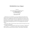
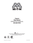
Video Loop-Back Application
Pictured below is an application using the Video Loop Back output
from a System 8/10 PLUS Switcher as the input to a Sentosaxi LQ
or a Lanciaxi LD. The output of the Sentosaxi/Lanciaxi is
connected back to the last input (input 8 or 10) of the System 8/10
PLUS Switcher. This technique enables Line Doubling/Line
Quadrupling for all inputs to the System 8/10 PLUS.
Sentosa or Lancia
Page 2-9
Extron • SENTOSAxi LQ & LANCIAxi LD • User’s Manual
Extron’s SENTOSAxi LQ & LANCIAxi LD
User’s Manual
3
Chapter Three
RS-232/REMOTE Control
RS-232 Control
Windows Compatible Software
Extron • SENTOSAxi LQ & LANCIAxi LD • User’s Manual
RS-232/REMOTE Control
RS-232/REMOTE Control
The Sentosaxi/Lanciaxi include an RS-232 communications
interface which allows it to be controlled from a Host device/
system. RS-232 connector pin assignments and protocol are
shown below.
To
Serial
Port
When RS-232 data is received by the Sentosaxi/Lanciaxi, the front
panel MIN LED will blink once then the MAX LED will blink once to
indicate that RS-232 data is being received. In EXEC mode the
MIN and MAX LEDs are solid ON (see Page 2-5), they don’t blink.
A contact closure device may also be used on the RS-232
connector, See “Remote Contact Closure Operation” – Page 3-5.
xi Communications
Host/Sentosaxi
xi/Lanciaxi
xi
The Sentosaxi/Lanciaxi treats any character that it receives on the
RS-232 port as a possible command but accepts only a limited
number as legal commands. There are no codes required to say
that a command is coming, or that a command has ended. A
simple command may be a single character typed on a keyboard
and does not require any special characters before or after. (i.e. It
is not necessary to press “enter” from the keyboard.) Simple
commands could be from a terminal, or any other Host device.
When the Sentosaxi/Lanciaxi receives a command and determines
that it is valid, it will execute the command and send a response
back to the controlling (Host) device. If the Sentosaxi/Lanciaxi
determines that the command is invalid, an error response will be
returned to the Host. All responses from the Sentosaxi/Lanciaxi to
the Host end with a carriage return and a line feed (CR/LF)
signaling the end of the Response character string (string = one or
more characters).
Using the Command/Response Table
The table on the following page lists those commands which the
Sentosaxi/Lanciaxi recognizes as valid and the responses that will
be returned to the Host. The Description column defines the
Command, the results of executing the Command, or a definition
of the response. An example of each command is shown to the
right of the Command Description column. The error response
format is shown at the bottom of the table. Possible error types
and causes are shown on page 3-3 followed by Sentosaxi/Lanciaxi
initiated messages.
A dot (·) when used in the table represents a space. It is not
displayed.
Page 3-1
Extron • SENTOSAxi LQ & LANCIAxi LD • User’s Manual
= 1 – 127
= 0 or 1, 0 = OFF, 1 = ON
= Software version x.xx
= 1 – 63
Example Commands and Responses
Response
Action/Explanation
Page 3-2
C2
Select Input channel #2
Frz1
Freeze (Frame) Video
Frz0
Release Freeze Mode
C2·T1·Col65·Tin70·Con100·Hph39·Frz0
C2·T1·Col65·Tin70·Con100·Hph39·Frz0
N60-213-01
60-213-01 = Lancia
N60-229-01
60-229-01 = Sentosa
QVER·1.23
(1.23 is example only)
QVER·1.23
Software version 1.23
Col25
Color value to 25
Col26
Color value + 1
Col25
Color value – 1
Tin32
Tint value to 32
Tin33
Tint value + 1
Tin32
Tint value – 1
Con99
Contrast value to 99
Con100
Contrast value + 1
Con99
Contrast value – 1
Hph39
Set H. Phase Value to 39
Hph40
Horiz. Phase Value + 1
Hph39
Horiz. Phase Value – 1
see “Error Responses” – next page
RS-232/REMOTE Control
Extron • SENTOSAxi LQ & LANCIAxi LD • User’s Manual
COMMAND/RESPONSE TABLE
Definitions and Abbreviations:
= CR/LF
· = space
= 1 or 2 (Input #)
= Input type (T), 0 = no input, 1 = NTSC 3.58, 2 = PAL, 3 = NTSC 4.43, 4 = SECAM
COMMAND
RESPONSE
ASCII HEX
to Host
Command Description
Command
!
21h C
Select input channel (C)
2!
h
F
7Ch
Frz1
Freeze ON (ASCII F or | accepted)
F
f
7Eh
Frz0
Freeze OFF (ASCII f or ~ accepted)
f
i
69h
(Same as I below)
Information request
i
I
49h
C ·T ·Col ·Tin ·Con ·Hph ·Frz
I
n
6Eh
(Same as N below)
Request for part number
n
N
4Eh
N60-213-01
Request for part number
N
q
71h
(Same as Q below) Query software version
q
Q
51h
QVER·
Query software version
Q
C
43h Col
Set color value (Col) to
25C
h
{C 7Bh43h Col
Increment color value
{C
}C 7Dh43h Col
Decrement color value
}C
T
54
Tin
Set
tint
value
(Tin)
to
32T
h
h
{T
7Bh54h Tin
Increment tint value
{T
}T 7Dh54h Tin
Decrement tint value
}T
^
5E
Con
Set
contrast
value
(Con)to
99^
h
h
{^
7Bh5Eh Con
Increment contrast value
{^
}^ 7Dh5Eh Con
Decrement contrast value
}^
H
48
Hph
Set
horizontal
phase
value
(Hph)
to
39H
h
h
{H 7Bh48h Hph
Increment Hph value
{H
}H 7Dh48h Hph
Decrement Hph value
}H
Exx
Error Response
RS-232/REMOTE Control
Time-out
Pauses 10 seconds or longer between command sequence ASCII
characters will result in a Time-out. The command operation is
aborted with no other indication that a Time-out has occurred.
Error Responses
•
•
•
•
When a command is received from the Host, if the Sentosaxi/
Lanciaxi detects an error, it will return an error response. Possible
error responses with a brief description follow:
E01 Invalid input channel number (out of range)
E06 Auto-switch mode active (rear panel DIP switch #1 =enable)
E10 Invalid command (Command received is invalid)
E13 Invalid value (out of range)
xi
Sentosaxi
xi/Lanciaxi
xi-Initiated Messages
xi
When a local event takes place, such as a front panel operation or
an error condition, the Sentosaxi/Lanciaxi responds by sending a
message to the Host. No response from the Host is expected.
These Sentosaxi/Lanciaxi-initiated messages are listed below
(underlined to identify actual message).
(C) Copyright 1998, Extron Electronics (Model), V x.xx
This message is initiated by the Sentosaxi/Lanciaxi when it is first
powered on. (Model = Sentosaxi or Lanciaxi), (x.xx is the software
version number)
Reconfig
This message is initiated by the Sentosaxi/Lanciaxi
when there is a change in the selected input or any
picture control setting.
RS-232 - Overrun
These Sentosaxi/Lanciaxi-initiated messages
indicate an RS-232 communication error.
Possible causes are RS-232 connection
problem, Baud rate, etc.
RS-232 - Noise
RS-232 - Framing
RS-232 - Overflow
RAM Test Failed
ROM Checksum Failed
Serial EEPROM Checksum Failed
6811 EEPROM Checksum Failed
New 6811 Installed
Call Extron Technical Support if
any of these Sentosaxi/Lanciaxiinitiated messages are reported.
New Serial EEPROM Installed
Invalid Jumpers - Unknown - xxxx
Factory Defaults Reset on Channel #1
Factory Defaults Reset on Channel #2
Page 3-3
Call Extron Technical Support.
Reported if Freeze button is
depressed during power-up.
Extron • SENTOSAxi LQ & LANCIAxi LD • User’s Manual
RS-232/REMOTE Control
Lancia/Sentosa Control Software
The Lancia/Sentosa Control Program is Windows® compatible
and provides remote control of the following functions:
•
•
•
Input selection
Video adjustments
Freeze frame control
Installing the Software
The program is contained on a single 3.5” diskette and will run
from the floppy drive. However, it will be more convenient to load
and run it from the hard drive. It can be installed on the user’s
hard-drive as follows:
1.
2.
Insert the Extron software diskette into the floppy drive.
From the Windows Program Manager File menu, click on
Run.
3. Specify the disk drive and type “setup”. For example, type
A:\SETUP if the diskette is in drive A.
The program will occupy approximately 1 MB of hard drive space.
The Windows installation will create (by default) a C:\LANCIA
directory and will place 2 icons (LANCIA/SENTOSA Control
Program and LANCIA/SENTOSA Help) into a group titled “Extron
Electronics”.
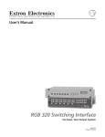
Using the Software
1.
For information about program features, double click on the
LANCIA/SENTOSA Help ICON in the Extron Electronics
group. [Help can be accessed from its Icon (stand-alone) or
from within the program by the Menu on the Main screen or
by pressing F1 from any point within the program.]
2.
To run the software, double click on the LANCIA/SENTOSA
Control Program ICON in the Extron Electronics group.
3.
A Comm menu will be displayed on the screen. Click on the
Comm Port that is connected to the Lanciaxi/Sentosaxi
RS-232 connector.
4.
The Extron LANCIA/SENTOSA Control Program window
displays current input selection and control values (see Figure
3-4 below).
Figure 3-4
Extron • SENTOSAxi LQ & LANCIAxi LD • User’s Manual
Page 3-4
RS-232/REMOTE Control
Remote Contact Closure Operation
The RS-232 connector provides a way to control the Sentosaxi/
Lanciaxi using a remote contact closure device. This is made
possible through the use of pins that are not normally used by the
RS-232 interface. The contact closure pin assignments are shown
below
Pin #
5
6
7
8
9
RS-232
Function
Ground
Input #1
Input #2
Tally #1
Tally #2
H
H/V
SOG
REMOTE
V
To select a different input
number through the RS-232
connector, momentarily short
the pin for the desired input
number (#) to logic ground (pin
5). To force one of the two inputs
to be selected continuously, leave the short to logic ground in
place, this will override front panel input selection.
The Tally pins can be used for remote indication of the selected
input. Tally #1 or Tally #2 (pins 8 and 9) will indicate the selected
input # with a logic low (0 volts), the Tally pins are normally at
logic high (5 volts).
The schematics shown below may be used as a guide to design
and build indicator circuits for the Tally pins. Since there is no
voltage source on the RS-232 connector, an external voltage
source will be required.
LED Indicator Circuit
Incandescent Lamp Circuits
RECOMMENDED RELAYS
EXTERNAL POWER
EXTERNAL
+5V+5VDC
(PIN 13)
Using an
Opto-isolator
& External Power
MANUFACTURER
GENERAL
Aromat
ITT/Panasonic
Omron
DS2
R-Z-5C
G5Y
RESISTOR VALUE
DEPENDS ON CURRENT
REQUIREMENT OF LAMP
LOW CURRENT
TQ
A5W
G6H
EXTERNAL
+5V
(PIN 13)
+5VDC
330 Ohm
LED
EXTERNAL
+5VDC
+5V (PIN 13)
TALLY PIN
N/C
Using a Relay
& External
Power
1N916
330 Ohm
TALLY PIN
Page 3-5
TALLY PIN
EXTERNAL POWER
Extron • SENTOSAxi LQ & LANCIAxi LD • User’s Manual
Extron’s SENTOSAxi LQ & LANCIAxi LD
User’s Manual
A
Appendix A
Other Reference Material
Remote Contact Closure Operation
Accessories and Part Numbers
Limited Warranty
Extron • SENTOSAxi LQ & LANCIAxi LD • User’s Manual
Other Reference Material
Accessories/Part Numbers
BNC-4 HR Cable
BNC-4-3’HR (3 feet/0.9 meters) ........................................................... 26-210-01
BNC-4-6’HR (6 feet/1.8 meters) ........................................................... 26-210-02
BNC-4-12’HR (12 feet/3.6 meters) ....................................................... 26-210-03
BNC-4-25’HR (25 feet/7.5 meters) ....................................................... 26-210-04
BNC-4-50’HR (50 feet/15.0 meters) ..................................................... 26-210-05
BNC-4-75’HR (75 feet23.0 meters) ...................................................... 26-210-06
BNC-4-100’HR (100 feet/30.0 meters) ................................................. 26-210-07
BNC-4-150’HR (150 feet/45.0 meters) ................................................. 26-210-08
BNC-4-200’HR (200 feet/60.0 meters) ................................................. 26-210-09
BNC-4-250’HR (250 feet/75.0 meters) ................................................. 26-210-54
BNC-4-300’HR (300 feet/90.0 meters) ................................................. 26-210-53
BNC-4 Mini-HR Bulk (300’/90m up to 5000’/1500m) ........................... 22-073-01
BNC-5 HR Cable
BNC-5-3’HR (3 feet) ............................................................................. 26-260-15
BNC-5-6’HR (6 feet/1.8 meters) ........................................................... 26-260-01
BNC-5-12’HR (12 feet/3.6 meters) ....................................................... 26-260-02
BNC-5-25’HR (25 feet/7.5 meters) ....................................................... 26-260-03
BNC-5-50’HR (50 feet/15.0 meters) ..................................................... 26-260-04
BNC-5-75’HR (75 feet23.0 meters) ...................................................... 26-260-16
BNC-5-100’HR (100 feet/30.0 meters) ................................................. 26-260-05
BNC-5-150’HR (150 feet/45.0 meters) ................................................. 26-260-12
BNC-5-200’HR (200 feet/60.0 meters) ................................................. 26-260-06
BNC-5-250’HR (250 feet/75.0 meters) ................................................. 26-260-18
BNC-5-300’HR (300 feet/90.0 meters) ................................................. 26-260-14
BNC-5 Mini-HR Bulk (300 feet up to 5000 feet) ................................... 22-008-01
Lanciaxi Line Doubler ........................................................................... 60-213-02
Sentosaxi Line Quadrupler ................................................................... 60-229-02
Sentosaxi/Lanciaxi Label ...................................................................... 33-244-01
Sentosaxi/Lanciaxi User’s Manual ........................................................ 68-254-01
19” 1U Universal Rack Shelf ................................................................ 60-190-01
RCA-6’ - RCA Male to Male, 6 feet/1.8 meters .................................... 26-345-01
SVHS (S-Video) Extension Cables
SVHS-6’ - Male to Male S-Video Cable, 6 feet/1.8 meters .................. 26-316-02
SVHS-12’ - Male to Male S-Video Cable, 12 feet/3.6 meters .............. 26-316-03
SVHS-20’ - Male to Male S-Video Cable, 20 feet/6 meters ................. 26-316-01
SVHS-30’ - Male to Male S-Video Cable, 30 feet/9.1 meters .............. 26-316-04
SVHS-50’ - Male to Male S-Video Cable, 50 feet/15 meters ............... 26-316-05
SVHS-75’ - Male to Male S-Video Cable, 75 feet/23 meters ............... 26-316-06
SVHS-100’ - Male to Male S-Video Cable, 100 feet/30 meters ........... 26-316-07
Page A-1
Extron • SENTOSAxi LQ & LANCIAxi LD • User’s Manual