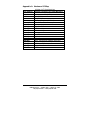
1
Not Recommended for New Installations. Please contact Technical Support for more information. Stable Real Time Clock for PCs Model PCRTC Documentation Number PCRTC2095 This product Designed and Manufactured In Ottawa, Illinois USA of domestic and imported parts by B&B Electronics Mfg. Co. Inc. 707 Dayton Road -- P.O. Box 1040 -- Ottawa, IL 61350 PH (815) 433-5100 -- FAX (815) 433-5105 Internet: http://www.bb-elec.com [email protected] [email protected] B&B Electronics March 1995 Documentation Number PCRTC2095 Manual Cover Page B&B Electronics -- PO Box 1040 -- Ottawa, IL 61350 PH (815) 433-5100 -- FAX (815) 433-5105 Table of Contents CHAPTER 1. GENERAL INFORMATION ....................................1 INTRODUCTION ........................................................................................1 PACKING LIST ..........................................................................................1 SPECIFICATIONS .......................................................................................1 CHAPTER 2. SETUP ..........................................................................2 HARDWARE SETUP...................................................................................2 TABLE 1. ADDRESS SWITCH SETTINGS ...................................................2 HARDWARE INSTALLATION .....................................................................3 SOFTWARE SETUP ....................................................................................3 CHAPTER 3. OPERATION...............................................................4 OVERVIEW ...............................................................................................4 USING THE DEVICE DRIVER .....................................................................4 COMMAND LINE OPTIONS........................................................................5 SETTING THE PCRTC TIME AND DATE ...................................................5 REPLACING THE BATTERY .......................................................................6 PROGRAMMING WITH THE PCRTC ..........................................................6 QUICKBASIC PROGRAMMING EXAMPLE ..............................................10 PASCAL PROGRAMMING EXAMPLE ........................................................10 C PROGRAMMING EXAMPLE ..................................................................11 CHAPTER 4. CALCULATING ERROR........................................12 PPM TERMINOLOGY ..............................................................................12 OSCILLATOR ERROR ..............................................................................12 APPENDIX A. HARDWARE I/O MAP..........................................14 Documentation Number PCRTC2095 Manual Table of Contents B&B Electronics -- PO Box 1040 -- Ottawa, IL 61350 PH (815) 433-5100 -- FAX (815) 433-5105 i Chapter 1. General Information Introduction The PCRTC is real time clock for PCs based on a highly stable oscillator circuit. Using the software driver provided, the PCRTC will update the DOS clock every minute, ensuring that all applications have access to accurate time information. With a simple function call, the PCRTC also reports battery status and the time of the last power loss or computer reset. Packing List Examine the shipping carton and contents for physical damage. The following items should be in the shipping carton: 1. PCRTC unit 2. One PCRTC 3.5” disk 3. This instruction manual If any of these items are damaged or missing contact B&B Electronics immediately. Specifications Setup Address: Programmable with four position DIP switch Interrupt: None required Oscillator Temperature Stability: < 5 ppm 0 - 50 °C Calibration: < 1 ppm @ 23 °C (room temperature) Aging: < 1 ppm Power Requirements 35 mA @ 5VDC Battery Requires lithium AA battery 3-4V Battery Life: approximately 10K hr. without host computer powered. Replacement batteries are available from B&B Electronics, order as part number 3345. Dimensions: 4.8” l x 3.0” h Documentation Number PCRTC2095 Manual B&B Electronics -- PO Box 1040 -- Ottawa, IL 61350 PH (815) 433-5100 -- FAX (815) 433-5105 1 Chapter 2. Setup Hardware Setup The address switch on the PCRTC must be set to an address which doesn’t conflict with other devices in the host computer. The address settings are listed in Table 1, and are also printed on the PCRTC card. The PCRTC is shipped from the factory set for 200h. If you need to change this address, select one from the table which will not conflict with another device in the host computer. If the PCRTC does not operate properly, select a new address. Remember to edit the file CONFIG.SYS to match the device driver address to that used by the hardware. Appendix A contains a hardware I/O address map for AT class PCs. Table 1. Address Switch Settings Hex Switch Settings Address 1234 200 0000 220 1000 240 0100 260 1100 280 0010 2A0 1010 2C0 0110 2E0 1110 300 0001 320 1001 340 0101 360 1101 380 0011 3A0 1011 3C0 0111 3E0 1111 2 Documentation Number PCRTC2095 Manual B&B Electronics -- PO Box 1040 -- Ottawa, IL 61350 PH (815) 433-5100 -- FAX (815) 433-5105 Hardware Installation 1. 2. 3. 4. Shut the host computer power off. Remove the computer cover. Remove the expansion slot cover of an unused slot. Handle the PCRTC only by its edges. Avoid touching any conductors on the PCRTC. Install the PCRTC into the slot. Be certain that the card is inserted completely into the slot. 5. Secure the card with the mounting screw from the slot cover. The PCRTC is shipped with the oscillator halted to extend battery life. To start the PCRTC, the card must be initialized. This can be done using the command line option PCRTC /I found in Chapter 3 of this manual or by the device driver. If you are using the device driver, it will automatically initialize the PCRTC when it loads. Upon initialization, a warning will appear stating that the oscillator was halted and date and time information may be corrupt. Software Setup Place the 3.5” floppy disk in your “A” drive. Run the installation program by typing “INSTALL” <Enter>. The files installed to your hard drive include the PCRTC device driver, the shareware program Timeset and three example files written in C, Pascal, and QuickBASIC. These files demonstrate how to make function calls to the PCRTC from within a program and are listed in Chapter 3. The device driver will also be automatically installed in your CONFIG.SYS file and set for address 200. If you require a different address, remember to edit the CONFIG.SYS file to set the address to match PCRTC hardware. Documentation Number PCRTC2095 Manual B&B Electronics -- PO Box 1040 -- Ottawa, IL 61350 PH (815) 433-5100 -- FAX (815) 433-5105 3 Chapter 3. Operation Overview The most common application of the PCRTC is to simply maintain the correct time on the host computer. Loading the device driver in the CONFIG.SYS file will accomplish this function by setting the DOS clock to the PCRTC clock time once every minute. This allows the user and all applications access to the correct time without any special commands or function calls. The PCRTC has two additional features which may either be incorporated using the provided “include file” and making function calls within your program, or from the command line using the PCRTC.EXE file. The first of these functions is battery status. By checking the battery status you can take action on a low battery before the time is corrupted. The second function is the time of last power loss or reset. By checking this function, the time of the last host computer power loss or system reset can be determined. Using the Device Driver In order for the PCRTC to automatically update the DOS clock, the device driver PCRTCDD.SYS must be loaded from CONFIG.SYS. This is done automatically by the installation program. The following line will be added to the CONFIG.SYS file: DEVICE = {path}PCRTCDD.SYS /A:{hex PCRTC address} For example, if the file PCRTCDD.SYS is in the directory C:\PCRTC, and the card address is set to 200h, use the following line. DEVICE = C:\PCRTC\PCRTCDD.SYS /A:200 If the address 200 is not compatible with your hardware, the address parameter must be changed to match the address that was selected for the hardware. After modifying the CONFIG.SYS file, reboot the host computer. If the hardware and driver are installed correctly, you should see the following message during bootup. 4 Documentation Number PCRTC2095 Manual B&B Electronics -- PO Box 1040 -- Ottawa, IL 61350 PH (815) 433-5100 -- FAX (815) 433-5105 PCRTC v1.00, (c) Copyright 1995, B&B Electronics Mfg. Co. PCRTC address: 200h Battery Status: Good If this message appears, the driver has been installed and is running. The DOS clock will be updated every minute using the time from the PCRTC. The driver will report any errors found upon installation. Command Line Options All of the PCRTC features can be accessed and controlled from the command line as well. The program PCRTC.EXE has the following command line options. PCRTC /t [address] PCRTC /d [address] PCRTC /i [address] PCRTC /s [address] PCRTC /p [address] PCRTC /c [address] PCRTC /u [address] PCRTC /n [address] PCRTC /h+ [address] PCRTC /h- [address] PCRTC /PCRTC /+ Set PCRTC time Set PCRTC date Initialize PCRTC (after battery change) Display date, time and battery status Display time/date of last power down Display PCRTC and DOS clock Set PCRTC date/time to DOS date/time Set DOS date/time to PCRTC date/time Increment hours +1 for Daylight Savings Decrement hours -1 for Daylight Savings Disable PCRTCDD.SYS Enable PCRTCDD.SYS It is necessary to insert the PCRTC address [address] only if the device driver is not loaded. Note that the last two options are only available if the driver is loaded. These options may be displayed at the DOS prompt by typing PCRTC {enter}. Setting the PCRTC Time and Date There are several methods of setting the time and date of the PCRTC. To manually set the time and date, use the DOS TIME and DATE commands to first set the DOS clock, then use the /u command line option to set the PCRTC time and date to be equal to the DOS time and date. The time and date can also be set manually using the command PCRTC /t and PCRTC /d. This sets the PCRTC time and date without affecting the DOS time and date. Documentation Number PCRTC2095 Manual B&B Electronics -- PO Box 1040 -- Ottawa, IL 61350 PH (815) 433-5100 -- FAX (815) 433-5105 5 The best method of updating the PCRTC time is to use the shareware program Timeset. Note that although this program is included on the PCRTC diskette, it is shareware and should be registered with its author. Timeset uses your modem to obtain the precise time from one of five atomic clocks in two continents, then sets your DOS time. The batch file RTCSET.BAT included in the Timeset directory should be used in conjunction with Timeset. Running the batch file will execute the following operations. Note that the device driver PCRTCDD.SYS must be installed to run the batch file. Before running Timeset or the batch file, you will need to configure Timeset for your modem and preferences. Documentation files are included in the Timeset directory. 1. 2. 3. 4. 5. Update the DOS time to the PCRTC time Disable the device driver Run Timeset Update the PCRTC to the corrected DOS time Enable the device driver Using Timeset allows the PCRTC time to be updated to within ≤ 0.1 seconds of the atomic clock selected. The small discrepancy in time is dependent on the speed of the host computer and background activities on the host computer. Replacing the battery The PCRTC uses a lithium AA 3.6V battery to maintain its clock while the host computer is off. Replacement batteries must be rated between 3 and 4 volts. Batteries can be ordered through B&B as part number 3345. After replacing the battery, the PCRTC needs to be reinitialized. If the device driver loads in your config.sys file, the card will automatically be initialized, otherwise, the command line option PCRTC {address} /I can be used. After replacing the battery, the time and date must be reset. Programming with the PCRTC If you are writing your own application, you may wish to access the status features of the PCRTC in addition to accurate timekeeping. An “include” file for C, Pascal, and QuickBASIC is provided to allow simple function calls to check battery status and the time of last power down or reset. Sample programs demonstrating how to make these calls are provided in each of the three languages. The device driver keeps the DOS clock updated to the correct time, so accurate time can be obtained using the standard DOS calls. 6 Documentation Number PCRTC2095 Manual B&B Electronics -- PO Box 1040 -- Ottawa, IL 61350 PH (815) 433-5100 -- FAX (815) 433-5105 Start_RTC_API Purpose: Initializes API, must be the first PCRTC function called in the program. C: int Start_RTC_API(unsigned int address); Pascal: FUNCTION Start_RTC_API(address: WORD): WORD; BASIC: FUNCTION StartRTCAPI% (BYVAL address AS INTEGER) Remarks: Start_RTC_API takes the address at which the PCRTC is installed at. The device driver must be installed. Returns: 0 = device driver is not installed. non zero = address of PCRTC. Example: See below. Battery_RTC Purpose: Check battery status of PCRTC C: int Battery_RTC(void); Pascal: FUNCTION Battery_RTC: WORD; BASIC: FUNCTION BatteryRTC% Returns: 1 if battery is good 0 if battery is low Example: See below. Documentation Number PCRTC2095 Manual B&B Electronics -- PO Box 1040 -- Ottawa, IL 61350 PH (815) 433-5100 -- FAX (815) 433-5105 7 Get_RTC_Time Purpose : Returns the RTC time within a structure. C: struct GetTime_T { unsigned int hours; unsigned int min; unsigned int seconds; unsigned int h_seconds; }; int Get_RTC_Time(GetTime_T far *gt); Pascal : TYPE GetTime_T = RECORD hours: WORD; min: WORD; seconds: WORD; h_seconds: WORD; END; TYPE GetTime_Ptr = ^GetTime_T; FUNCTION Get_RTC_Time(time: GetTime_Ptr): WORD; BASIC: TYPE GetTimeT hours AS INTEGER min AS INTEGER seconds AS INTEGER hseconds AS INTEGER END TYPE FUNCTION GetRTCTime%(BYVAL Offs AS INTEGER, BYVAL Segm AS INTEGER) Remarks: Get_RTC_Time requires a far pointer to the GetTime_T structure to be past as the argument. Returns: The GetTime_T structure with the appropriate values. Example: See below. 8 Documentation Number PCRTC2095 Manual B&B Electronics -- PO Box 1040 -- Ottawa, IL 61350 PH (815) 433-5100 -- FAX (815) 433-5105 Last_Power_Down_RTC Purpose: Returns date and time of last power down within a structure. C: struct TimeSave_T { unsigned int month; unsigned int day; unsigned int hour; unsigned int minute; unsigned int second; }; int Last_Power_Down_RTC(TimeSave_T far *ts); Pascal: TYPE TimeSave_T = RECORD month: WORD; day: WORD; hour: WORD; minute: WORD; second: WORD; END; TYPE TimeSave_Ptr = ^TimeSave_T; FUNCTION Last_Power_Down_RTC(timeSave: TimeSave_Ptr): WORD; BASIC: TYPE TimeSaveT month AS INTEGER day AS INTEGER hour AS INTEGER minute AS INTEGER second AS INTEGER END TYPE FUNCTION LastPowerDownRTC% (BYVAL Offs AS INTEGER, BYVAL Segm AS INTEGER) Remarks: Last_Power_Down requires a far pointer to the TimeSave_T structure to be past as the argument. Returns: The TimeSave_T structure with the appropriate values. Example: See below. Documentation Number PCRTC2095 Manual B&B Electronics -- PO Box 1040 -- Ottawa, IL 61350 PH (815) 433-5100 -- FAX (815) 433-5105 9 QuickBASIC Example: '$INCLUDE: 'RTC_API.BI' ‘Must be first executed statement in your program DIM timeS AS TimeSaveT DIM time AS GetTimeT ‘Define Variable Structure address% = StartRTCAPI(0) ‘Initialize API IF (address% <> 0) THEN ‘Check that it initialized OK IF (GetRTCTime(VARSEG(time), VARPTR(time)) <> 0) THEN PRINT “RTC time: “; time.hours; “:”; time.min; “:”; time.seconds; “.”; PRINT time.hseconds END IF IF (LastPowerDownRTC(VARSEG(timeS), VARPTR(timeS)) <> 0) THEN PRINT "Last Power Down (Reset): "; timeS.month; "/"; timeS.day; PRINT "at"; timeS.hour; ":"; timeS.minute; ":"; timeS.second END IF IF (BatteryRTC) THEN ‘Check Battery Status PRINT "Battery Status: GOOD" ELSE PRINT "Battery Status: LOW" END IF ELSE PRINT "Device Driver (PCRTCDD.SYS) must be loaded." END IF END Pascal Programming Example USES RTC_API; VAR ts: TimeSave_Ptr; time: GetTime_Ptr; address: WORD; battery: WORD; BEGIN New(ts); New(time); address := Start_RTC_API(0); IF (address <> 0) THEN BEGIN IF (Get_RTC_Time(time) <> 0) THEN writeln(‘RTC time: ‘, time^.hours, ‘:’, time^.min, ‘:’, time^.second, ‘.’, time^.hseconds); IF (Last_Power_Down_RTC(ts) <> 0) THEN writeln('Last Power Down (Reset): ', ts^.month, '/', ts^.day, ' at ', ts^.hour, ':', ts^.minute, ':', ts^.second); IF (Battery_RTC <> 0) THEN writeln('Battery Status: Good') ELSE writeln('Battery Status: Low'); END ELSE writeln('Device Driver (PCRTCDD.SYS) must be installed.'); Dispose(ts); Dispose(time); END. 10 Documentation Number PCRTC2095 Manual B&B Electronics -- PO Box 1040 -- Ottawa, IL 61350 PH (815) 433-5100 -- FAX (815) 433-5105 C Programming Example #include <conio.h> #include "rtc_api.h" void main() { TimeSave_T *ts = (TimeSave_T *) malloc(sizeof(TimeSave_T)); GetTime_T *time = (GetTime_T *) malloc(sizeof(GetTime_T)); unsigned int battery; unsigned int address; cprintf("Demo (PCRTC-c) v1.00, (c) Copyright 1994, B&B Electronics Mfg. Co.\r\n\r\n"); address = Start_RTC_API(0); if (address) { if (Get_RTC_Time(time)) cprintf(“RTC time: %u:%u:%u.%u\r\n”, time->hours, time->min, time>seconds, time->h_seconds); if (Last_Power_Down_RTC(ts)) cprintf("Last Power Down (Reset): %.2u/%.2u at %u:%.2u:%.2u\r\n", ts->month, ts->day, ts->hour, ts->minute, ts->second); if (Battery_RTC()) cprintf("Battery Status: Good\r\n"); else cprintf("Battery Status: Low\r\n"); } else cprintf("Device Driver (PCRTCDD.SYS) must be installed.\r\n"); free(ts); free(time); } Documentation Number PCRTC2095 Manual B&B Electronics -- PO Box 1040 -- Ottawa, IL 61350 PH (815) 433-5100 -- FAX (815) 433-5105 11 Chapter 4. Calculating Error PPM Terminology The unit ppm (parts per million) provides a number similar to error expressed with percentages, but reduces the number of decimal places required. For example, 0.001% converts to 0.00001 which is equivalent to 10 ppm. Using the ppm notation makes it easier to deal with very small deviations. The ppm terminology is also useful for calculating PCRTC error in terms of seconds per month. Since an average month has approximately 2.63 million seconds, if the PCRTC error was 2 ppm total error for the month would be 2 x 2.63 = 5.26 seconds. Oscillator Error The precision of the PCRTC is entirely dependent on the quality of the oscillator circuit. There are three sources of error in the oscillator, and understanding them will allow you to estimate the precision of the PCRTC in your application. Calibration error The PCRTC oscillator is calibrated at the factory to within 1 ppm (part per million) of its specified frequency at room temperature (23 °C). Temperature Stability The frequency of oscillation of crystal oscillators is highly dependent on temperature. The oscillator used in the PCRTC has an extremely low temperature dependency of 5 ppm from 0 °C to 50 °C. Since the oscillator is calibrated to 1 ppm at room temperature (23 °C), it will only exhibit 1 ppm error if its environment is held to this temperature. The worst case condition is if the temperature of the PCRTC is held at one of the extremes, 0 or 50 °C. At these points, there will be an error of 5 ppm. If the temperature variation covers a smaller span, less error will be exhibited. 12 Documentation Number PCRTC2095 Manual B&B Electronics -- PO Box 1040 -- Ottawa, IL 61350 PH (815) 433-5100 -- FAX (815) 433-5105 Aging All crystal oscillators have an aging characteristic. The crystal used in the PCRTC uses the coldweld manufacturing technique, which exhibits the lowest aging characteristic of 1 ppm/year. In practice, this aging rate improves significantly with time, but for practical purposes the value of 1 ppm is adequate. To estimate the error in your application, sum the error from the three sources above. This estimate can be used to determine how frequently the time should be updated using Timeset or another method. Documentation Number PCRTC2095 Manual B&B Electronics -- PO Box 1040 -- Ottawa, IL 61350 PH (815) 433-5100 -- FAX (815) 433-5105 13 Appendix A. Hardware I/O Map Hex Address 000-00F 020-021 040-043 060-063 080-083 0A0-0AF 200-20F 210-217 2E8-2EF 2F8-2FF 300-31F 320-32F 378-37F 380-38F 3B0-3BF 3D0-3D7 3E8-3EF 3F0-3F7 3F8-3FF 14 I/O Map of XT Class Machines Address Function in XT Class Machines DMA controller (8237A) interrupt controller (8259A) timer (8253) PPI(8255A) DMA page register (74LS612) NMI - non maskable interrupt game port joystick controller expansion unit COM4 serial port COM2 serial port prototype card hard disk parallel print SDLC MDA - monochrome adapter and printer CGA - color graphics adapter COM3 serial port floppy diskette controller COM1 serial port Documentation Number PCRTC2095 Manual B&B Electronics -- PO Box 1040 -- Ottawa, IL 61350 PH (815) 433-5100 -- FAX (815) 433-5105 Hardware I/O Map of AT Class Machines Hex Address Address Function in AT Class Machines 000-01F DMA controller #1 (8237A-5) 020-03F interrupt controller #1 (8259A) 040-05F timer (8254) 060-06F keyboard (8042) 070-07F NMI - non maskable interrupt & CMOS RAM 080-09F DMA page register (74LS612) 0A0-0BF interrupt controller #2 (8259A) 0C0-0DF DMA controller #2 (8237A) 0F0-0FF 80287 math coprocessor 1F0-1F8 hard disk 200-20F game port joystick controller 258-25F Intel Above Board 278-27F parallel printer port 2 2E8-2EF COM4 serial port 2F8-2FF COM2 serial port 300-31F prototype card 378-37F parallel printer 1 380-38F SDLC or bisynch com 2 3A0-3AF bisynch com 1 3B0-3BF MDA - monochrome adapter 3BC-3BE parallel printer on monochrome adapter 3C0-3CF EGA - reserved 3D0-3D7 CGA - color graphics adapter 3E8-3EF COM 3 serial port 3F0-3F7 floppy diskette controller 3F8-3FF COM1 serial port Any eight byte space not listed above and not used by any other equipment in your system may be used for the serial port. Documentation Number PCRTC2095 Manual B&B Electronics -- PO Box 1040 -- Ottawa, IL 61350 PH (815) 433-5100 -- FAX (815) 433-5105 15