1
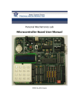
Personal Mechatronics Lab www.PML4all.org Matlab/Simulink Support Package ©2013 M.R. Emami Contents 1. Introduction .............................................................................................................................................. 2 1.1 Overview ............................................................................................................................................. 2 1.2 Features .............................................................................................................................................. 2 2. Operation .................................................................................................................................................. 2 2.1 Installation .......................................................................................................................................... 2 2.2 Step by Step Tutorial ........................................................................................................................... 3 2.2 While loop Tutorial ............................................................................................................................. 5 2.3 Subsystem Enable Tutorial .................................................................................................................. 8 3. Support for individual blocks .................................................................................................................. 11 3.1 MCU Peripherals Library ................................................................................................................... 11 3.1.1 Digital I/O ................................................................................................................................... 11 3.1.2 ADCInit ....................................................................................................................................... 12 3.1.3 ADCConvert ................................................................................................................................ 12 3.1.4 EEPROMInitialize ........................................................................................................................ 12 3.1.5 EEPROMWrite ............................................................................................................................ 12 3.1.6 EEPROMRead ............................................................................................................................. 13 3.1.7 External Interrupt....................................................................................................................... 13 3.1.8 Keypad........................................................................................................................................ 13 3.1.9 LCD Display ................................................................................................................................. 13 3.1.10 RS232 Custom Code ................................................................................................................. 13 3.1.11 PWM ........................................................................................................................................ 13 3.1.12 Capture..................................................................................................................................... 13 3.1.13 Compare ................................................................................................................................... 14 3.1.14 RTCInit ...................................................................................................................................... 14 3.1.15 RTCRead ................................................................................................................................... 14 3.1.16 RTCSet ...................................................................................................................................... 14 3.1.17 Custom Code Library ................................................................................................................ 14 3.2 Driver Board Library .......................................................................................................................... 15 3.3 Sensor Board Library ......................................................................................................................... 18 3.4 Utility Board Library .......................................................................................................................... 20 1 1. Introduction 1.1 Overview The Simulink PML (short for personal mechatronics laboratory) block set was designed as an interface between Simulink and the following 5 PML boards: Microcontroller board, Driver board, Sensor board, Utility board, and FPGA board. The use of this block set requires a basic working knowledge of Simulink. The main usage of this block set is to drag a few of the blocks into a new model, connect the blocks together, and then double click the generate code block. The Simulink coder will then generate a C code compatible with the selected PIC, and compile and burn the hex code directly onto the PIC if said options are selected. Also, this block set can be utilized to monitor the sensors on a sensor board, or control the motors on the driver board. 1.2 Features Open source, modular design with easy to understand parameters for beginners Supports code generation for the PIC16f877, PIC16f887, and PIC16f1937 Includes virtual input and output options for block ordering Code Section parameter to give users added flexibility Custom code blocks to enable users to embed their own C code MCU Peripherals library to interface with Microcontroller board Driver Board Library to monitor and control motors Sensor Board Library with analog and digital inputs Utility Board Library complete with oscilloscope External Applications Library to access important standalone applications Automatic code generation block Automatic code report open option Automatic hex code generation and hex code burning 2. Operation 2.1 Installation To install the Simulink PML block set, the folder SimulinkPML must be set to the MATLAB working directory. This folder is automatically installed when any of the PML applications are installed. Note, the folder SimulinkPML may need to be copied to a writable directory first. Next, the slblocks.m script must be ran. This script puts the Simulink PML library into the Simulink browser, under the name Simulink PML block set. The user must also ensure 2 that the Microchip xc8 compiler is installed correctly, and that the application xc8.exe is on the current MATLAB path. This can be confirmed by typing !xc8.exe in the MATLAB command window. 2.2 Step by Step Tutorial Open a new Matlab window. 3 Open the Simulink library browser. Click file -> new model. Under Simulink PML block set, drag a Pic Master block to your new model Add an LCD initialization block, LCD Display block and generate code block to your model and save it. 4 Link them together as such using the block ordering dialog parameter of each block. The parameters box is accessed by double clicking the block. To link blocks together, hold control and click the first block followed by the second block. Next choose the appropriate pic from the choose a pic dialog parameter in the Pic Master block. Double click generate code, then open PICusb and burn the hex file onto your desired PIC. Alternatively, you can also select the 'Burn Hex Code Automatically' parameter in the extra features tab of the Pic Master block. 2.2 While loop Tutorial Open a new Simulink model and name it WhileLoopTutorial. Drag a Pic Master block and Generate code block from the Simulink PML block set to the new model. This example will use the Pic16f877, and so it will be selected from the Pic Master block. 5 Next, drag a while subsystem block from the Ports and subsystems library under Simulink in the Simulink browser to your new model. Then add an LCD Init block and MCU Digital Input read block, and set the blocks as shown below. 6 Double click the While Iterator Subsystem block, and drag an LCD Display block and MCU Digital Input Read block inside the subsystem. Set up the subsystem as shown below. 7 Turn on the Create Hex Code automatically and Burn Hex Code Automatically options under the Extra Features tab in the Pic Master block as shown below. Then, connect your microcontroller board, ensure it is in program mode, and then double click the generate code block. This example will continually write the message, "You are pressing a key!" to the lcd while RB1 is high. The complete model can be found in the model WhileloopExample.mdl under the Samples folder. 2.3 Subsystem Enable Tutorial Open a new model and set it up as shown below. MCU Digital Input Read is found under the Digital I/O library of Simulink PML blockset. The Enabled subsystem blocks can be found under the Ports and Subsystems sublibrary under the Simulink library in the Simulink browser. The Compare to Zero block can be found under the logic library. Do not worry if there are currently input and output ports attached to the enable subsystem blocks. 8 Double click on each enabled subsytem block and set it up as shown below. The removal of the input and output blocks automatically get rid of the ports on the corresponding blocks. The mask of each LCD display block should appear as below, with the custom text being whatever you desire. It is important to note that the code section must be output. Likewise, the delay can be set to any arbitrary number, but for this example 500ms was selected. 9 This example displays Key Pressed on the LCD when a key is pressed, and Key not pressed when a key is not pressed. The complete model can be found in the model EnableSubsystemExample.mdl under the Samples folder. 10 3. Support for individual blocks 3.1 MCU Peripherals Library Figure 1- The Microcontroller Board Every block in the MCU peripherals library corresponds and controls a module on the Microcontroller board pictured above. For more information on each of the modules, refer to the sections below or to the microcontroller board user manual. 3.1.1 Digital I/O Every microcontroller that is inserted into the MCU board will have a number of pins which can be set to input or output. Traditionally, to set a pin to input, the user would set the associated TRIS bit in the program memory. For example, to set the pin RC7 to input, one would write the line bsf TRISC,7 in assembly syntax or TRISC7 = 1 in C syntax. 11 Conversely, to set the pin RC7 to output, one would write bcf TRISC,7 in assembly syntax or TRISC7 = 0 in C syntax. The digital I/O blocks are used to configure the I/O pins and clear or set the output pins, as well as to read the input pins. Before using any of the write or read blocks, the I/O configuration block must be implemented with the appropriate array of pins for each port being selected. A Matlab array takes the form "[1 2 3 4]". This block will essentially set or clear the aforementioned Tris bits in the program memory. The MCU Digital Output Write block accepts any Simulink block as input(s) and will set the pin of the pic associated with the input port to whatever state the input port is in. This input should be a boolean value. Note, this block only operates in the outputs function, any initialization of pins must be done using a custom code block. The MCU Digital Input Read block will output the state of the selected pins via its output ports at each simulation time step. The extended I/O blocks work in a similar fashion to the aforementioned blocks, however the I2C Setup block must be used before setting the I/O configurations. Also, the MCU must be in RUN mode for extended I/O to function. The MCU Digital Output Read block is a very different block intended for advanced users only. The main premise of the block is to create a link between Matlab and the register watcher standalone program. The use of the register watcher program requires a specific firmware. 3.1.2 ADCInit This block takes in a clock select and either right or left justified as parameters. The clock select determines what frequency the conversion will take place at. If left justified is selected then the 8MSB of the 10 bit conversion result will be placed in ADRESH, while the 2LSB will be placed in ADRESL. If right justified is selected, the opposite is true. 3.1.3 ADCConvert This block simply converts and analog to digital signal and outputs it as a 10 digit number. The user is able to select which channel he/she wants to be converted, and ADRESH and ADRESL will output from the top and bottom outputs respectively. This block only functions when its input is true. ADCInit must be placed in the model with this block, and it is strongly advised to set the analog pins to input with an I/O configuration block. 3.1.4 EEPROMInitialize EEPROMInitialize allows the user to set the first 8 values of EEPROM memory by entering a matrix of length 8. 3.1.5 EEPROMWrite This block functions in two modes, Input or custom values mode. The input mode accepts two inputs, the first one being the value to be written, and the second one being the 12 address to be written to. In custom value mode, the user inputs pairs of the form [address value] to be written to EEPROM. 3.1.6 EEPROMRead This block allows the user to read any EEPROM value by selecting how many addresses they wish to read, and inputted those addresses. The outputs correspond to EEPROM values of the entered addresses. 3.1.7 External Interrupt When the external interrupt block is double clicked a subsystem featuring a model source and model start block are shown. The model start block simply sets up the interrupt and the actual Interrupt service routine can be modified under the inter() function in model source. It is assumed that external interrupts occur on RB0. 3.1.8 Keypad The keypad block takes in an input purely for block ordering purposes. It can be placed in either the start or terminate code locations. The block will wait for the user to press a key and output the result as an unsigned char from 0-15. 3.1.9 LCD Display LCD Display operates in one of 2 modes, either input or custom text. In the input mode, the block accepts integer inputs and writes them to the lcd screen. In the custom text mode the user enters the custom text desired for each line of the lcd screen. The user has the option of selected either one or two lines, to clear the lcd before writing, and to go to a specific lcd location before writing in any of the two modes. The use of this block requires the LCDInit block to have been placed before it. 3.1.10 RS232 Custom Code The RS232 Custom Code block illustrates how to use blocks from the custom code library. The user may change any of the code within the block to suit the needs of what should be outputted via the RS232. The use of this block requires the RS232Init block to be placed before it. 3.1.11 PWM This block allows the user to create a pulse wave modulation using either the CCP1 or CCP2 modules. The use of this block requires RC1 and RC2 to be set as outputs, and the period and CCPRxL values can be entered. The CCPRxL value determines the duty cycle. The prescalar for timer2 can also be set from the mask dialog. 3.1.12 Capture This block sets either the CCP1 or CCP2 modules to capture mode. The user can select when they want the capture of timer1 contents to occur. The options are either every falling edge, rising 13 edge, 4th rising edge, and 16th rising edge of RC2. The block ordering is purely for the initialization setup of timer 1. This block outputs CCPR1L and CCPR1H which will contain the contents of the last capture of timer1. 3.1.13 Compare This block sets either the CCP1 or CCP2 modules to compare mode. The user can select what value they want to compare TMR1 to be setting the CCPRxH and CCPRxL parameters. TMR1 is a 16 bit timer, so CCPRxH and CCPRxL should both be 8 bit numbers. Next, the mode can be selected from the drop down menu. Low to high mode, changes pin CCPx pin(RC2 or RC1) from low to high when the compare values match up. High to low mode does the exact opposite. IRQ mode requests an interrupt service routine, while special event trigger causes analog to digital conversion to run. 3.1.14 RTCInit This block is used as the initialization for RTC. RTCInit block requires I2C Setup block. All RTC blocks rely on a DS1307 IC with lithium ion battery, the appropriate I2C firmware, and having jumpers on both JP6 and JP7. 3.1.15 RTCRead This mask requires four parameters, value, digit, block ordering, and code location. Value is chosen from a popup menu, and allows the user to select from either Year, Month, Date, Day, Hours, Minutes, or Seconds. Digit allows the user to select either the tens digit or the ones digit of the aforementioned value. RTCInit block must be implemented to use this block. 3.1.16 RTCSet This mask requires allows the user to reset all, or set the date, time, time format, AM/PM, and day of the week. Reset all sets all values to 0. RTCInit block must be implemented to use this block. 3.1.17 Custom Code Library The Custom Code library is very similar to the Simulink Coder library, and includes some similar blocks. Basically, The System Start, Outputs, Terminate and Initialize blocks allow you to place any pic compliant C code into any of these four main sections of code. The VersatileCustomCode block allows the user to select virtual inputs and outputs for block ordering as well as the specific code section. Model Header, and Model Source allow for custom code to be added to the model header or model source respectively. EmbeddedCustomInitCode takes the name of a file in the current working directory, and embeds the contents within the start function. CustomInit Function takes the name of a C code, puts that C code into a function, creates a header for the function, and then calls the function in the specified function of the main code. 14 3.2 Driver Board Library Figure 2 - An overview of the driver board The Driver Board V 3.0 has been designed with the user in mind. It is an educational printed circuit board that offers a complete method to test and understand motor drivers. The Driver Board is capable of running 2 DC motors, 1 unipolar stepper motor, 1 bipolar stepper motor, 1 servo motor and 1 brushless DC motor and it provides the user the option of running the motors either manually, using an external microcontroller or using the computer application software. Figure 2 shows an overview of the complete driver board split into separate modules. Table 1 on the following page provides a brief description of each of the modules. 15 Table 1 - Description of driver board modules 16 Open UnipolarMotorExample in the Samples folder. The model should appear as shown below. To monitor and control any motor in the Driver Board library, involves three simple steps. First, the block must be double clicked to open the control GUI as shown below. Next, the scope should be opened and the simulation should be started. Finally, the user must click the play button on the control GUI to see the results display on the scope. Note, the Pic master block is only included to set the appropriate solver parameters. The Driver board library was expanded to add a motor controller block. This motor controller block takes the type of motor as a parameter. Depending on the type of motor, different options such as duty cycle, direction, and enable are provided as inputs to the block. Putting the first input as a 1 turns on the motor, whereas 0 turns it off. Putting the second input as 1 makes the motor move forward whereas 0 makes it go reverse. Duty cycle values 17 range from 0-4. All other motors can be controlled and monitored in a similar manner as shown by the unipolar motor above. 3.3 Sensor Board Library Figure 3 - Picture of the Sensor board The main purpose of the sensor board library is to monitor the signals of the sensros attached to the sensor board pictured above in Figure 3. An example of how to use the Input Monitor block in the sensor library is shown below. Open SensorBoardInputMonitorExample in the Samples folder. 18 To monitor and control any input sensor, double click the Input Monitor block and select a sensor after connecting the sensor board. Open the scope block and press simulate. Setting the simulation time depends how long the simulation will run for. The scope block is shown below. The top graph will display the signal, while the middle and bottom graphs display the max and min respectively. 19 3.4 Utility Board Library Figure 4 - Overview of utility board 20 The utility board library is used to monitor either channel A, B, A+B or the signal generated by the utility board pictured in figure 4. Below is a tutorial on how to use the Channel A block in the utility board library. Open UtilityBoardChannelAExample in the Samples folder. It should appear as shown below. Double click the channel A block. The GUI below should appear. Press the play button after connecting the Utility board. Signals should appear on the gui. 21 Next, open the scope and run the simulation. The voltage of channel A and average of channel A will appear on the scope. The other blocks in this library work in a similar fashion to the channel A block shown above. 22