1
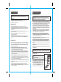
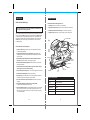
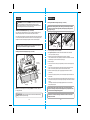
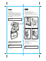
Operator’s Manual
1/3 Sheet
Pad Sander
Model No. 172.117020
Double Insulated
CAUTION: Read, understand and follow
all Safety Rules and Operating Instructions
in this manual before using this product.
Sears Brands Management Corporation,
Hoffman Estates, IL 60179 U.S.A.
www.sears.com
3025736
• WARRANTY
• SAFETY
• UNPACKING
• DESCRIPTION
• ASSEMBLY
• OPERATION
• MAINTENANCE
6/4/12
TABLE OF CONTENTS
SAFETY SYMBOLS
Warranty……………………………...................................……………...Page
Safety Symbols……………………………...................................……... Page
Safety Instructions…………………………...................................……..Pages
Unpacking.………………………………..................................……........Page
Description............................................................................................Pages
Assembly...............................................................................................Pages
Operation..............................................................................................Pages
Maintenance......................................................................................... Page
Accessories...........................................................................................Page
Parts List...............................................................................................Pages
2
3
4- 9
9
10-11
12-16
17- 20
21
22
23-24
CRAFTSMAN ONE YEAR LIMITED WARRANTY
FOR ONE YEAR from the date of purchase, this product is warranted against
any defects in material or workmanship. With proof of purchase, a defective
product will be replaced free of charge.
For warranty coverage details to obtain free replacement, visit the web site:
www.craftsman.com
This warranty does not cover the sanding sheets, which are expendable parts
that can wear out from normal use within the warranty period.
This warranty is void if this product is ever used while providing commercial services
or if rented to another person.
This warranty gives you specific legal rights, and you may also have other rights
which vary from state to state.
Sears Brands Management Corporation, Hoffman Estates, IL 60179
The purpose of safety symbols is to attract your attention to possible dangers. The
safety symbols and the explanations with them deserve your careful attention and
understanding. The symbol warnings do not, by themselves, eliminate any danger.
The instructions and warnings they give are no substitutes for proper accident
prevention measures.
WARNING: Be sure to read and understand all safety instructions in this
manual, including all safety alert symbols such as “DANGER,” “WARNING,” and
“CAUTION” before using this pad sander. Failure to follow all instructions listed in
this manual may result in electric shock, fire and/or serious personal injury.
SYMBOL SIGNAL MEANING
SAFETY ALERT SYMBOL: Indicates DANGER, WARNING, OR CAUTION.
May be used in conjunction with other symbols or pictographs.
DANGER: Indicates a hazardous situation which, if not avoided, will result
in death or serious injury. This signal word is to be limited to the most extreme
situations. Always follow the safety precautions to reduce the risk of fire, electric
shock, and personal injury.
WARNING: Indicates a hazardous situation which, if not avoided, could result
in death or serious injury. Always follow the safety precautions to reduce the risk
of fire, electric shock, and personal injury.
CAUTION: Indicates a hazardous situation which, if not avoided, could
result in minor or moderate injury.
Damage Prevention and Information Messages
These inform the user of important information and/or instructions that could lead
to equipment or other property damage if they are not followed. Each message is
preceded by the word “NOTE,” as in the example below:
NOTE: Equipment and/or property damage may result if these instructions are not
followed.
WARNING: To ensure safety and reliability, all repairs
should be performed by a qualified service technician.
SAVE THESE INSTRUCTIONS!
READ ALL INSTRUCTIONS!
! WARNING: Some dust created by using power tools contains chemicals
known to the State of California to cause cancer and birth defects or other
reproductive harm.
2
WARNING: The operation of any power tools can result in
foreign objects being thrown into your eyes, which can result in
severe eye damage. Before beginning power tool operation,
always wear safety goggles or safety glasses with side shield
and a full face shield when needed. We recommend a Wide
Vision Safety Mask for use over eyeglasses or standard safety glasses with side
shields. Always use eye protection which is marked to comply with ANSI Z87.1
shields.
3
SAFETY INSTRUCTIONS cont.
SAFETY INSTRUCTIONS
!
WARNING: Read all safety warnings and instructions. Failure to follow
the warnings and instructions may result in electric shock, fire and/or
serious injury.
Save all warnings and instructions for future reference.
The term power tool in the warnings refers to your electric (corded) power tool or
battery-operated (cordless) power tool.
WORK AREA SAFETY
1. Keep work area clean and well lit. Cluttered or dark areas invite accidents.
2. Do not operate power tools in explosive atmospheres, such as in the presence of
flammable liquids, gases or dust. Power tools create sparks which may ignite the
dust or fumes.
3. Keep children and bystanders away while operating a power tool. Distractions can
cause you to lose control.
4. Make your workshop childproof with padlocks and master switches. Lock
tools away when not in use.
5. MAKE SURE the work area has ample lighting so you can see the work and that
there are no obstructions that will interfere with safe operation BEFORE using your
power tool.
PERSONAL SAFETY
1. Stay alert, watch what you are doing and use common sense when operating a
power tool. Do not use a power tool while you are tired or under the influence of
drugs, alcohol or medication. A moment of inattention while operating power tools
may result in serious personal injury.
2. Use personal protective equipment. Always wear eye protection. Protective
equipment such as dust mask, non-skid safety shoes, hard hat, or hearing protection
used for appropriate conditions will reduce personal injuries.
3. Prevent unintentional starting. Ensure the switch is in the off-position before
connecting to power source and/or battery pack, picking up or carrying the tool.
Carrying power tools with your finger on the switch or energizing power tools that have
the switch on invites accidents.
4. Remove any adjusting key or wrench before turning the power tool on. A wrench
or a key left attached to a rotating part of the power tool may result in personal injury.
5. Do not overreach. Keep proper footing and balance at all times. This enables better
control of the power tool in unexpected situations.
6. Dress properly. Do not wear loose clothing or jewelry. Keep your hair, clothing and
gloves away from moving parts. Loose clothes, jewelry or long hair can be caught in
moving parts.
7. If devices are provided for the connection of dust extraction and collection
facilities, ensure these are connected and properly used. Use of dust collection can
reduce dust-related hazards.
4
TOOL USE AND CARE SAFETY
! WARNING: BE SURE to read and understand all instructions before
operating this power tool. Failure to follow all instructions listed below may
result in electric shock, fire and/or serious personal injury.
1. Do not force the power tool. Use the correct power tool for your application. The
correct power tool will do the job better and safer at the rate for which it was designed.
2. Do not use the power tool if the switch does not turn it on and off. Any power tool
that cannot be controlled with the switch is dangerous and must be repaired.
3. Disconnect the plug from the power source and/or the battery pack from the
power tool before making any adjustments, changing accessories, or storing
power tools. Such preventive safety measures reduce the risk of starting the power
tool accidentally.
4. Store idle power tools out of the reach of children and do not allow persons
unfamiliar with the power tool or these instructions to operate the power tool.
Power tools are dangerous in the hands of untrained users.
5. Maintain power tools. Check for misalignment or binding of moving parts,
breakage of parts and any other condition that may affect the power tools
operation. If damaged, have the power tool repaired before use. Many accidents
are caused by poorly maintained power tools.
6. Keep cutting tools sharp and clean. Properly maintained cutting tools with sharp
cutting edges are less likely to bind and are easier to control.
7. Use the power tool, accessories and tool bits etc., in accordance with these
instructions and in the manner intended for the particular type of power tool,
taking into account the working conditions and the work to be performed. Use of
the power tool for operations different from those intended could result in a hazardous
situation.
8. Use clamps or another practical way to secure and support the workpiece to a
stable platform.
9. Holding the work by hand or against your body leaves it unstable and may lead
to loss of control.
! WARNING: Empty dust bag before storage to help prevent possible fire
hazard, especially when resin coating or linseed oil finishes have been sanded.
ELECTRICAL SAFETY
! WARNING: Do not permit fingers to touch
the terminals of plug when installing or removing
the plug from the outlet.
1. Double insulated tools are equipped with a polarized
plug (one blade is wider than the other). This plug
will fit in a polarized outlet only one way. If the plug
does not fit fully in the outlet, reverse the plug. If it still
does not fit, contact a qualified electrician to install a
polarized outlet. Do not change the plug in any way.
5
Cover of
Grounded
Outlet Box
SAFETY INSTRUCTIONS cont.
SAFETY INSTRUCTIONS cont.
ELECTRICAL SAFETY
! WARNING: Do not permit fingers to touch the terminals of plug when
installing or removing the plug from the outlet.
2. Power tool plugs must match the outlet. Never modify the plug in any way. Do not
use any adapter plugs with grounded power tools. Unmodified plugs and matching
outlets will reduce risk of electric shock.
! WARNING: Double insulation DOES NOT take the place of normal safety
precautions when operating this tool.
3. Avoid body contact with grounded surfaces such as pipes, radiators, ranges and
refrigerators. There is an increased risk of electric shock if your body is grounded.
4. Do not expose power tools to rain or wet conditions. Water entering a power tool
will increase the risk of electric shock.
5. Do not abuse the cord. Never use the cord for carrying, pulling or unplugging the
power tool. Keep cord away from heat, oil, sharp edges or moving parts. Damaged
or entangled cords increase the risk of electric shock.
6. When operating a power tool outdoors, use an extension cord suitable for outdoor
use marked “W-A” or “W”. Use of a cord suitable for outdoor use reduces the risk of
electric shock.
7. If operating a power tool in a damp location is unavoidable, use a Ground Fault
Circuit Interupter (GFCI) protected supply. Use of a GFCI reduces the risk of
electric shock.
EXTENSION CORDS
USE PROPER EXTENSION CORD. Make sure your extension cord is in good condition.
When using an extension cord, be sure to use one heavy enough to carry the current your
product will draw. An undersized cord will cause a drop in line voltage resulting in loss of
power and overheating. Table 1 shows the correct size to use depending on cord length and
nameplate ampere rating. If in doubt, use the next heavier gage. The smaller the gage
number, the heavier the cord.
Table 1: Minimum Gage for Cord
Rating
Volts
! WARNING: Check extension cords before each use. If damaged replace
immediately. Never use tool with a damaged cord since touching the damaged
area could cause electrical shock, resulting in serious injury.
SAFETY SYMBOLS FOR YOUR TOOL
The label on your tool may include the following symbols.
V.......................................................................Volts
A...................................................................... Amps
Hz.................................................................... Hertz
W..................................................................... Watts
min..................................................................Minutes
....................................................................Alternating current
...............................................................Direct current
no ....................................................................No-load speed
....................................................................Class II construction, Double Insulated
.../min.............................................................. Revolutions or Strokes per minute
OPM.................................................................Orbits Per Minute
! ....................................................................Indicates danger, warning or caution.
It means attention! Your safety is involved.
SERVICE SAFETY
1. If any part of this tool is missing or should break, bend, or fail in any way;
or should any electrical component fail to perform properly: SHUT OFF the
power switch and remove the tool’s plug from the power source and have the
missing, damaged or failed parts replaced BEFORE resuming operation.
2. Have your power tool serviced by a qualified repair person using only identical
replacement parts. This will ensure that the safety of the power tool is maintained.
3. If the replacement of the supply cord is necessary, this has to be done by the
manufacturer or his agent in order to avoid a safety hazard.
SAFETY RULES FOR POWER SANDERS
Total cord length (in feet)
! CAUTION: Keep the extension cord clear of the working area. Position the
cord so that it will not get caught on lumber, tools or other obstructions while
you are working with a power tool.
1. HOLD TOOL by insulated gripping surfaces when sanding where tool may contact
hidden wiring, such as walls, floors, or its own power cord. Contact with a “live” wire will
make exposed metals parts of the tool “live” and shock the operator.
2. INSPECT FOR AND REMOVE all nails, screws, staples or any embedded pieces
of metal from surface to be sanded. These protrusions could damage the sandpaper,
the cushion of the sander and cause loss of control. Following this rule will reduce the
risk of serious personal injury and damage to the sander.
3. NEVER use this or any power sander for wet sanding or liquid polishing.
Failure to follow this rule will increase the risk of electric shock.
4. ALWAYS clamp the workpiece securely so it will not move under the sander.
Unsecured work could be thrown towards the operator, causing injury.
5. DO NOT force the sander. The weight of the sander supplies adequate
pressure. Let the sander and the grit on the sandpaper do the work.
6. DO NOT sand in any one place for too long. The sander’s rapid action may
remove too much material and make the surface uneven.
6
7
120V
Ampere
More Than
0
6
10
12
Not More
Than
25
50
100
150
AWG
6
10
12
18
18
16
16
16
16
16
14
12
16
14
14
14
12
12
Not recommended
SAFETY INSTRUCTIONS cont.
! WARNING: Some dust created by using power tools contains chemicals
known to the State of California to cause cancer and birth defects or other
reproductive harm. Some examples of these chemicals are:
• Lead from lead-based paints.
• Crystalline silica from bricks and cement and other masonry products.
• Arsenic and chromium, from chemically treated lumber.
Your risk from these exposures varies, depending upon how often you do
this type of work. To reduce your exposure to these chemicals:
• Work in a well-ventilated area.
• Work with approved safety equipment, such as those dust masks that
are specially designed to filter out microscopic particles.
Avoid prolonged contact with dust from power sanding, sawing, grinding,
drilling and other construction activities. Wear protective clothing and wash
exposed areas with soap and water. Allowing dust to get into your mouth,
eyes, or lay on the skin may promote absorption of harmful chemicals.
! WARNING: Use of this tool can generate and/or disburse dust, which may
cause serious and permanent respiratory or other injury. Always use
NIOSH/OSHA approved respiratory protection appropriate for the dust exposure.
Direct particles away from face and body.
ADDITIONAL RULES FOR SAFE OPERATION
! WARNING: BE SURE to read and understand all instructions.
Failure to follow all instructions listed below may result in electric shock, fire
and/or serious personal injury.
1. Harmful/toxic dusts will arise from sanding e.g. lead painted surfaces, woods and metals.
Contact with or inhalation of these dusts can endanger the health of operator and
bystanders. Always use eye glasses and dust mask.
2. Hearing protection should be worn when using the sander.
3. Always wear safety glasses or eye shields when using the sander. Everyday eyeglasses have only impact-resistant lenses; they are not safety glasses. Following
this rule will reduce the risk of serious personal injury.
4. Remove the plug from the socket before carrying out any adjustment, servicing or
maintenance.
5. Fully unwind cable drum extensions to avoid potential overheating.
6. When an extension cable is required you must ensure it has the correct ampere rating for
your power tool and is in a safe electrical condition.
7. Ensure your mains supply voltage is same as indicated on the rating plate.
8. Your tool is double insulated for additional protection against a possible electrical
insulation failure within the tool.
9. Always check walls, floors and ceilings to avoid hidden power cables and pipes.
10. After long working periods external metal parts and accessories could be hot.
11. If possible, ensure the work-piece is firmly clamped to prevent movement.
12. Your sander is a hand held tool, do not clamp your sander.
13. Before sanding, check the area is free of nails, screws, etc.
14. Never stop the sander by applying a force to the base plate.
15. Only use paper in good condition. Do not use torn or worn paper.
16. Do not sand material containing asbestos due to a health risk.
8
SAFETY INSTRUCTIONS cont.
ADDITIONAL RULES FOR SAFE OPERATION cont.
17.
18.
19.
20.
21.
22.
23.
24.
Do not sand lead based paint due to the risk of lead poisoning.
Do not eat or drink in the working area of the sander.
Do not allow people to enter the working area without wearing a dust mask.
Where possible, seal off the working area to contain the dust for later removal.
Your tool is designed for dry sanding only, not wet sanding.
Your tool is designed for general purpose light polishing of wood and metals.
Do not sand magnesium material due to the risk of fire.
SAVE THESE INSTRUCTIONS. Refer to them frequently and use them to instruct
others who may use this tool. If someone borrows this tool, make sure they have
these instructions also.
UNPACKING
! WARNING: This power tool should NEVER be connected to the power
source when you are assembling parts, making adjustments, installing or
removing sandpaper, cleaning or when it is not in use. Disconnecting the sander
will prevent accidental starting, which could cause serious personal injury.
1. Remove the sander from the carton and inspect it carefully to make sure that no
breakage or damage has occurred during shipping.
2. Do not discard any of the packing materials until all parts are accounted for.
3. Included with your sander is a dust bag assembly.
4. 3 sheets of sandpaper are included; one 80 grit, one 100 grit, and one 120 grit.
5. Also included is a paper punch template, and a vac adapter for hook-up to a wet /dry
vac, sold separately.
6. If any of the parts are damaged or missing (refer to PARTS LIST below), return the
sander to your nearest Sears store or Craftsman outlet to have the sander replaced.
! WARNING: If any parts are missing, DO NOT operate this power tool until
the missing parts are replaced. Failure to do so could result in possible serious
personal injury.
PARTS LIST (Fig. 1)
1. Sander
2. Dust Bag Assembly
(comes attached to sander)
3. Vac Adapter
4. Three Sanding Sheets
6. Storage/
Carrying Case
7. Operator’s
Manual
5. Paper Punch Template
9
DESCRIPTION
DESCRIPTION cont.
KNOW YOUR PAD SANDER (Fig. 2)
This Pad Sander has the following features cont.:
12. Vac adapter allows hook-up to wet/dry vac (sold separately)
NOTE: Before attempting to use your sander, familiarize yourself with all of the
operating features and safety requirements.
Your 1/3-sheet pad sander has a precision-built electric motor and it should be connected
to a 120-volt, 60-Hz AC ONLY power supply (normal household current). DO NOT operate
on direct current (DC). The large voltage drop will cause a loss of power and the motor
will overheat. If the sander does not operate when plugged into correct 120-volt, 60-Hz
AC ONLY outlet, check the power supply. This sander has a 8-ft., 2-wire power cord
(no adapter needed).
13. High impact-resistant housing helps protect tool from damage and reduces weight
14. Permanently lubricated 100% ball bearings for smooth operation and long life.
15. Storage /Carrying Case for easy carrying and storage of sander and accessories.
On / Off Slide Switch
Fig 2
This Pad Sander has the following features:
1. Powerful 2.0 amp motor provides the torque, power and durability for a variety of
continuous sanding applications.
2. 12,000 orbits per minute with 1/16-in. orbit diameter matched with the correct
sandpaper grit for the surface being sanded provides fast material removal and/or a
fine, smooth finish.
3. Ergonomically designed rear handle and front assist handle with molded-in
comfort grip for maximum balance, control and gripping comfort.
Rear Handle
Front
Assist
Handle
Live Tool
Indicator
green LED
light
Paper Clamp
Dust Bag
Assembly
4. Precision-tuned counterbalanced system reduces vibration for smooth operation
and less operator fatigue.
Platen
5. On/Off slide switch is conveniently located for easy control. Sealed to keep out
dust for long life. Lock-on for continuous sanding.
6. Live Tool Indicator green LED light comes on when sander is plugged into a power outlet.
Platen
Slot
Sandpaper
7. Die-cast aluminum sanding base stands up to heavy-duty use.
8. Two paper clamps, one located at the front of the sander and the other at the back,
provide secure paper retention and simple, fast paper changes.
9. The cushion located on the bottom of the sander accepts standard non-adhesive
sandpaper.
10. Uses 1/3-sheet sandpaper to provide a 25-sq. in. sanding surface.
3 sandpaper sheets included (80, 100 and 120 grit).
11. Built-in dust collection system with removable dust bag assembly. This system collects
dust from work surface through the 10 holes located in the platen and cushion on the
bottom of the sander. A paper punch template is included for accurately punching holes
in the 1/3-sheet sandpaper.
10
Paper
Clamp Lever
PRODUCT SPECIFICATIONS
No-load Speed
12,000 OPM (Orbits Per Minute)
Rating
120 Volts, 60 Hz AC
Input
2.0 Amps
Orbit Diameter
1/16 in.
Paper Size
1/3 Sheet
Paper Type
Non-Adhesive Sandpaper
11
Cushion
ASSEMBLY cont.
ASSEMBLY
! WARNING: Your sander should NEVER be connected to the power source
when you are assembling parts, making adjustments, installing or removing
sandpaper, cleaning or when it is not in use. Disconnecting the sander will prevent
accidental starting, that could cause serious personal injury.
INSTALLING THE SANDPAPER (See Figs. 3, 3a, 3b and 4)
This sander has a cushion that allows you to use non-adhesive sandpaper. The nonadhesive sandpaper clamps to the front and back of the platen and cushion.
Installing Non-Adhesive Sandpaper (See Figs. 3 , 3a and 3b)
NOTE: Remove dust bag assembly when installing non-adhesive paper. ALWAYS
remember to reattach the dust bag assembly before beginning sanding operation
(see pages 16, Fig. 6).
Fig 3b
Fig 3a
This sander has a dust collection system that collects dust from the worksurface through
10 holes located in the platen and cushion on the bottom of the sander. A paper punch
template is included for accurately punching holes into the 1/3-sheet sandpaper.
NOTE: Holes must be punched into the paper for the dust collection system to
work properly. See instructions on page 14 to punch holes.
Clamp
Move lever
down to
raise clamp
Paper Goes
Under Clamp
Raise lever
up to clamp
paper
2. If replacing sandpaper, remove old sandpaper.
Installing Non-Adhesive Sandpaper (See Figs. 3, 3a and 3b)
3. Two paper clamp levers are located on each side of the sander and are locked into
a slot on top of the platen (see Fig. 3).
Fig 3
4. Raise these two levers “UP” and disengage them from the slots in the platen.
This will release the tension on the paper clamps located at the front and back of the sander
that hold the paper in position on the cushion (see Fig. 3a).
Paper
Clamp
Paper Goes
Under Clamp
Paper
Clamp
Paper
Goes
Under
Clamp
Cushion
Platen
Non-Adhesive
Sandpaper
Platen
Slot
Paper
Clamp
Lever
ALWAYS inspect the sandpaper before installing. DO NOT use if broken or defective.
1. Unplug the sander.
! WARNING: Failure to unplug the sander could result in accidental starting
causing possible serious personal injury.
12
5. Remove old paper.
6. Insert front end of a new sheet of paper approximately 1/2-inch under the front paper clamp
(see Fig. 3b).
7. Lift up on the lever that controls the front paper clamp and lock it back into the slot on the
platen. This will securely clamp the paper to the front of the sander’s cushion.
8. Smooth out the sheet of paper by pressing it tightly against the bottom of the cushion
(front to back).
9. Insert back end of paper approximately 1/2-inch under the paper clamp located at the back
of the sander.
10. Lift up on the lever that controls the paper clamp located at the back of the sander and lock it
back into the slot on the platen. This will securely clamp the paper to the back of the sander’s
cushion.
The sandpaper should now be positioned tightly against the cushion from front to back,
securely clamped in place.
NOTE: ALWAYS be sure that both paper clamp levers are in the locked position on
the platen and both paper clamps have the sandpaper securely clamped to the bottom
of the cushion before starting sanding operation.
NOTE: Never use the sander without paper attached to the cushion. This will cause
damage to the cushion.
13
ASSEMBLY cont.
ASSEMBLY cont.
PAPER PUNCH (See Figure 4)
A paper punch template is included with sander so you can punch properly aligned holes
into the sandpaper. This is done after the paper is installed onto the sander.
To punch holes, line up the front and side of the sander over the paper punch template as
shown in Fig. 4, then lower the sander onto the template while applying pressure. Make
sure the holes are punched all the way through the paper and clear the holes in the
sander’s cushion and platen.
NOTE: Punching holes properly is a necessary step for the dust collection
system to operate properly.
TO REMOVE AND EMPTY DUST BAG cont. (See Fig. 5)
3. Remove the dust bag / wire adapter from the dust bag assembly by sliding it down
and out of the slots in the assembly (see Fig. 5a).
4. Remove the bag from the wire frame and shake aggressively to completely empty the bag.
(see Fig. 5b)
Fig 5
Dust Bag
Assembly
Fig 4
Dust
Exhaust Hole
Adapter
Dust Bag
Fig 5b
Fig 5a
Orient Paper Punch
as shown
TO REMOVE AND EMPTY DUST BAG (See Fig. 5, page 15)
1. Unplug the sander.
! WARNING: Failure to unplug the sander could result in accidental starting
causing possible serious personal injury.
2. Remove dust bag assembly from the sander by pulling it straight back and out of the
sander (see Fig. 5, page 15).
14
5. When the bag is empty attach bag back onto the wire frame adapter (see Fig. 5b).
Make sure the bag is fastened up to, and tightly around, the adapter.
6. Slide dust bag / wire adapter up into the slots on the dust bag assembly (see Fig. 5a)
until they snap into position.
7. Attach dust bag assembly back into the sander.
8. Your sander is now ready to use.
NOTE: Empty dust bag frequently when sanding so dust collection system
works properly
15
ASSEMBLY cont.
!
OPERATION
WARNING: Empty dust bag before storage to help prevent possible fire
hazard, especially when resin coating or linseed oil finishes have been sanded.
NOTE: For more efficient operation, we recommend that you empty the dust bag when
it is no more than half full. This will allow the air to flow through the bag better. ALWAYS
empty and clean the dust bag thoroughly when you've finished sanding and before you
store the sander.
ATTACHING THE VAC HOSE ADAPTER (See Fig. 6)
Your sander includes a vac hose adapter that easily attaches to the sander.
The adapter allows you to hook your sander up to your wet/dry vac (sold separately).
1. Unplug the sander.
! WARNING: Failure to unplug the sander could result in accidental starting
causing possible serious personal injury.
2. Remove dust bag assembly from the sander by firmly holding the dust bag assembly
and pulling it straight out.
3. Insert vac hose adapter into the dust exhaust hole.
4. Push in adapter until the raised edges on the top and bottom of the adapter snap
into the grooves in the dust exhaust hole.
5. Firmly attach the vac hose adapter to your vac hose.
6. Attach vac hose to your wet/dry vac.
Before attempting to use any tool, be sure to familiarize yourself with all the
operating features and safety instructions.
! WARNING: IF ANY PARTS ARE MISSING, DO NOT OPERATE YOUR
SANDER UNTIL THE MISSING PARTS ARE REPLACED. FAILURE TO FOLLOW
THIS RULE COULD RESULT IN SERIOUS PERSONAL INJURY.
! WARNING: DO NOT let familiarity with your sander make you careless.
Remember that a careless fraction of a second is sufficient to cause severe injury.
ON/OFF SLIDE SWITCH
This switch is conveniently located on the top, front of the rear handle.
Start the sander by sliding the switch forward to the On position and letting the
motor build to its maximum speed before starting sanding operation.
APPLICATIONS
Only use your sander for the applications listed below.
• Sanding wood surfaces with various grits of sandpaper.
• Removing rust from steel surfaces with special sandpaper.
! CAUTION: ALWAYS be careful not to let your hand cover the air vents.
! WARNING: Unsecured work could be thrown towards the operator causing injury.
Fig 7
Fig 6
Dust Exhaust Hole
Vac
Hose Adapter
16
17
OPERATION cont.
OPERATION cont.
USING YOUR SANDER (See Fig. 7)
1.
2.
3.
4.
5.
ALWAYS clamp and secure the workpiece to prevent it from moving under sander.
ALWAYS hold your sander in front and away from you, keeping it clear of the workpiece.
Start the sander and let the motor build to its maximum speed.
Gradually lower the sander onto the workpiece with a slight forward movement.
Move the sander slowly, guiding it in a forward and backward motion.
SANDING TIPS
1. DO NOT force the sander. The weight of the sander supplies adequate pressure on
the workpiece. Let the sander and the sandpaper’s grit do the work.
• Applying additional pressure will only slow down the motor, wear the sandpaper
out faster and reduce the sander’s orbital speed.
• Excessive pressure will overload the motor and cause possible damage to the
sander from the motor overheating.
• Excessive pressure will also result in a poor quality finish.
2. Any existing finish or resin on wood may soften from the heat of the friction and cause
the sandpaper to load-up faster.
3. Inspect sandpaper frequently and change paper when grit is worn and not able to
perform properly.
4. DO NOT sand in one spot for too long a time because the sander’s rapid action may
remove too much material and make the surface uneven.
NOTE: ALWAYS continue sanding with each grit until the surface is uniform.
NOTE: DO NOT use the sander without sandpaper. This will damage the cushion.
! WARNING:DO NOT wear loose clothing or jewelry when operating sander.
They could get caught in moving parts, causing serious injury. Keep head away from
sander and sanding area. Hair could be drawn into sander, causing serious injury.
! WARNING:Empty dust bag before storage to help prevent possible fire
hazard, especially when resin coating or linseed oil finishes have been sanded.
NOTE: Empty dust bag frequently when sanding so dust collection system
works properly.
ORBITAL MOTION (See Fig. 8)
As shown in Figure 8, the orbit of the sander is 1/16-inch in diameter so the sandpaper
moves in tiny circles at high speed.
SELECTING THE RIGHT SANDPAPER
Selecting the correct grit and type of sandpaper is an extremely important decision that
will allow you to achieve the best quality sanding finish.
1. Aluminum oxide, silicon carbide and other synthetic abrasives are best for power
sanding.
2. Natural abrasives such as flint and garnet are too soft for economical use in power
sanding.
3. Coarse grit will remove the most material and finer grit will give you the best finish in all
sanding operations.
4. The condition of the surface to be sanded will determine which grit will do the job.
5. If the surface is rough:
A. Start with a coarse grit and sand until the surface is uniform.
B. Then use medium to remove any scratches left by the coarse grit.
C. Then use a finer grit for finishing the surface.
This orbital action duplicates a “hand sanding” motion for more aggressive sanding as you
push the sander forward. This powerful orbital action is ideal for heavy-duty sanding
applications, such as:
1. Removing old finishes
2. Smoothing rough wood
3. Sanding stock down to
required dimensions
4. Finishing surfaces that
are to be painted
Fig 8
1/16-in Orbital
Diameter
18
19
24
MODEL NUMBER 172.117020
1/3 Sheet Pad Sander
1
2
3
4
5
6
7
8
9
10
11
12
13
14
15
16
17
18
19
20
21
Item No.
PFS220BU-1
PFS220BU-2
PFS220BU-3
PFS220BU-4
PFS220BU-5
PFS220BU-6
PFS220BU-7
PFS220BU-8
PFS220BU-9
PFS220BU-10
PFS220BU-11
PFS220BU-12
PFS220BU-13
PFS220BU-14
PFS220BU-15
PFS220BU-16
PFS220BU-17
PFS220BU-18
PFS220BU-19
PFS220BU-20
PFS220BU-21
Parts No.
Power plug and cord
Cord protector
Cable clamp
Connection pole
Switch
Slider switch pole
Carbon brush
Bearing
Pin
Screw
Led
Inner wire
Insert
Insert sleeve
Inner wire
Rotor
Bearing
Stator
Aluminium fan
Bearing
Flitter support
Part Description
1
1
1
1
1
1
2
1
4
2
1
1
2
2
1
1
1
1
1
1
2
Qty.
22
23
24
25
26
27
28
29
30
31
32
33
34
35
36
37
38
39
40
41
42
Item No.
Part Description
Screw
Washer
Paper clamp
Base plate
Aluminium plate
Sponge plate
Washer
Spring washer
Screw
Right housing
Screw
Screw
Dust bag support
Steel wire support
Steel wire support
Dust bag cover
Screw
Dust bag
Left housing
Screw
felt ring
Parts No.
PFS220BU-22
PFS220BU-23
PFS220BU-24
PFS220BU-25
PFS220BU-26
PFS220BU-27
PFS220BU-28
PFS220BU-29
PFS220BU-30
PFS220BU-31
PFS220BU-32
PFS220BU-33
PFS220BU-34
PFS220BU-35
PFS220BU-36
PFS220BU-37
PFS220BU-38
PFS220BU-39
PFS220BU-40
PFS220BU-41
PFS220BU-42
The model number will be found on the nameplate of the pad sander.
Always mention the model number in all correspondence regarding your tool.
PARTS LIST cont.
2
2
2
1
1
1
1
1
1
1
15
1
1
1
1
1
4
1
1
10
1
Qty.