1
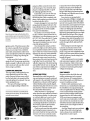
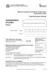
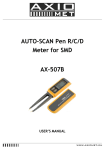
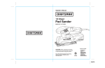
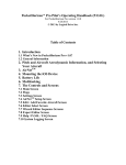
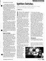
System Maintenance
(Continued from previous page)
Combine that with a shimmy that
induces a rapid back-and-forth vibration and the bearing blocks gall with the
added stress. The same can be said for
steering collars, rod end hardware, and
steering tube dampeners.
The cumulative clearances and the
extra wear rates result in a dynamic oscillation that starts as a slight lateral shimmy
of the nose wheel and ends with a violent
shaking of the entire airplane. It's as if
everything has come loose in the fuselage
and only good living and the blessings
of the Almighty are enough to hold the
crumbling bird together. It's at times like
these that just getting back to the ramp
with all the pieces intact is considered a
job well done.
Some steering collars can be shimmed
to reduce the vertical and lateral play on
the strut, and rod ends can be replaced
with new parts. Be certain to check the
steering rod attach points and the rudder
pedal torque tubes for loose bolts, worn
linkages, and egg-shaped bearing blocks.
If a nose wheel shimmy has been allowed
to continue, you can be assured that these
components have been adversely affected
by the strain.
SHIMMY IN THE EXTREME
Extreme nose wheel shimmy conditions
can cause collateral damage to cowling mount supports, tube steel engine
mounts, instrument panel supports, and
primary flight instruments. It also makes
landing operations much more difficult,
even for the experienced pilot.
Heavy braking tends to intensify the
problem by loading the nose wheel. The
natural reaction is to pull back on the
elevator, which will lessen the severity
of the shimmy but makes directional
control more difficult.
The NTSB has a file dedicated solely
to those aircraft that have departed the
runway for this very reason. It is in your
best interest to determine the cause of any
shimmy problem and make the necessary
repairs to the nose wheel and steering system as soon as possible.
As always, if in doubt about hardware
location, or if you are unsure about how
loose or tight an assembly should be,
consult your mechanic and the aircraft
maintenance and service manual.
www.lightplane-maintenance.com
Ignition Switches
The key start ignition switch has evolved into a many
functioned and complicated piece ofgear.
BY
LPM STAFF
t will leave you with a nagging doubt
until the duties of the take-off roll
pry your attention away from that
damn loose ignition switch. The
magnetos checked fine on run-up
but the mag switch tumblers are completely worn out.
The key can be removed at any time,
regardless of position, and the switch
detent has long since relieved itself from
the original deSign. That dark brood of
a thought only comes back for a brief
instant as the elevator takes hold and you
ease the nose off the ground-knowing
full well that any loss in power at this
point would put you somewhere between
the trees and the dirt.
It has long been known that the key
style locks and ignition switches used in
aviation applications years ago were not
assembled from materials and design
criteria that included the idea that you
would be flying this bird 40 years later.
Weighing only seven ounces, the average
key-type ignition switch is a compromise in weight, material, function and
purpose; and yet, the little twist-to-start
switch will outlast virtually any accessory
or component attached to the airframe.
It's an enigma to be sure, but in large part,
it works, and works well, conSidering
that the average ignition switch will cycle
some 5,300 times over the course of an
engine's life.
In the early 1940s magneto switches
were made by Mil Spec suppliers who
built large, heavy, rotating switches, which
were used to alternately
ground and open the
magneto primary leads.
Bendix took up the
lucrative line in April of
1947 when they introduced a low profile,
lightweight switch,
which performed the
same grounding function as their predecessors
I
at a better price to the makers.
In its Simplest form, the Bendix ignition switch provides individual operation
of either magneto while providing other
detents for both and off. The operation of
this switch and all variations of the unit
is made up of functions that selectively
ground the magneto P-Iead (or primary
lead) on the magneto you don't want
operating and opening the lead to the
magneto you want on line.
Ifboth mags are to be on line, then
«Both" is selected and the left and right pleads are opened. If«Off" is selected, then
both magnetos are grounded through
the switch to an airframe ground point
and all ignition function is removed. This
design criteria has been in place since the
dawn of time and is born of the assumption that a wire will break open before it
grounds out, thus providing ignition to
the engine in a system-fail mode. (Never
mind that the magneto P-Iead is encased
in a steel shield braid intended to limit
noise while offering a prime path for
ground with only a little bit of chafing.)
TWIST AND START
In 1960, Bendix produced the new generation of magneto Switches, which were
The Bendix "Ground Magneto" switch (GM) is an
ignition switch in its simplest form. Note the
remote starter button located to the left of the
mag switch.
APRIl2011 . .
Removing the ignition switch from the panel
can be an involved procedure in some aircraft.
Once free from its mounting, note the proper
location of all wiring.
designed with the same basic function as
earlier designs but now included options
for starter motor functions and "Shower
of Sparks" ignition sequencing. The
line continues today with four different
Bendix ignition switch configurations
offered, all of which are available for use
with a key or lever for rotation.
The old standard used in the 1940's
was the off-right-left-both switch (or
Ground Magneto style switch), which
required the application of hand-propping or use of some remote, push-type
starter switch. Used extensively for many
years, this simple design and limited
function switch was the mainstay of the
aviation business. Its sole function was to
alternately open and ground the selected
magneto, as required.
As systems became more complex and
The back plate of this Gerdes (ACS) switch shows
the many terminal connections used in the
typical Twist-to-Start switch.
. . APRIL 2011
BINDING AND ELECTRICAL FAILURE
Ignition switch problems are generally described as electrical faults or may
involve some mechanical failure. Occasionally, one problem leads to the other,
especially when the switch carries a start
feature with the magneto grounding
circuit.
The most common complaints heard
about the mag switch are that the internal
workings of the tumblers are too loose or
that the detent action isn't well defined.
Normal wear and tear contributes to this
kind of problem, requiring the replacement of the key action at a minimum
and often times requiring whole switch
replacement if the detent spring is broken.
The reverse of this situation is found
when the switch is so tight that no positive detent is felt during the mag check,
leaving you with the uncertain task of
finding some null spot where both mags
are on line at the same time. Generally,
a tight switch is the result of improper
lubrication, binding of the tumblers in
the case or a mechanical interference due
to a broken detent spring in the housing.
While the magnetos' grounding function
will usually work fine when the switch
has become damaged, the lack of positive
selection will always leave you with some
maintenance facilities have a difficult
time keeping track ofkeys.
Often enough, mechanics are asked
to open doors and start aircraft with tool
box keys, security gate devices and an assortment of pins, pliers and instruments
of the pointed variety. This takes its toll
on the mag switch and eventually switch
repair or replacement will be necessary.
Electrical failure of the ignition switch
is a direct result of coupling the starter
motor circuit to the magneto primary
lead circuit. This is accomplished inside
the magneto switch by tying a series
of contacts together using one or more
contact cups. These pie-shaped pieces of
metal are spring loaded against the switch
contacts and ride over the plate as the
switch is rotated.
When the switch is turned to the start
function, battery current is passed to the
starter contactor, which closes the relay
and energizes the starter. At the same
time, the switch will open the P-lead to
the left magneto and ground the lead to
the right.
This is commonly done to engines
equipped with a left mag impulse coupling, "Shower of Sparks" ignition system
or those supplied with a retard set of
breaker points. The right magneto is disabled because it will try to kick the engine
back during the start sequence if it has no
provisions to retard the spark.
Some magnetos are equipped with
dual impulse couplings, which would
then remove the isolation function of the
mag switch during start, allowing both
mags to assist in the start sequence. (It
should be noted that the wisdom or the
need for two impulse couplings has been
discussed at length and many of these
installations have been changed back to
the Single coupling arrangement.)
This start feature within the switch
has posed some contact problems due to
normal arcing that occurs during switch
actuation. Burned points, loss of point
anxiety, especially when you absolutely
material and high resistance plague not
must have both magnetos firing at their
maximum potential.
While the mag switch can be damaged
by misuse and outright abuse, the most
common cause for mechanical failure
is repeated use of the switch function.
Normal wear and tear is expected and
the Bendix switch can take years and
years of such use. However, it has long
been known that aircraft partners and
only the start function but can affect
the reliability of magneto grounding
and other peripheral circuits controlled
by the switch. While the old GM style
switch needed no special attention due to
the little current carried by the magneto
P-Iead circuit, the new Ground Battery
Magneto (GBM) switches found regular
maintenance to be a necessity.
Disassembly, cleaning and proper
panel space made a premium, the
standard ignition switch evolved
into a tightly bundled mass of
wires, contacts and circuits. We
now have twist-to-start, push-toprime, push-to-start and a couple
of individual variations of the lot.
With the use of starting vibrators,
fuel boost pumps, starting relays
and hot wire overrides, the simple
on-off ignition switch has become
a thing of the past, replaced by a
multi-function, hot-wired, impulse-signaling monster wrapped
up in coat of pot metal with a
plastic end cap attached.
LIGHT PLANE MAINTENANCE
lubrication are required from time to
time, particularly for aircraft operating in
corrosive environments or with electrical systems where proper grounding is a
problem. Bendix recommends cleaning
and repair as conditions warrant or when
the switch is made accessible.
In the case of the Cessna Cardinal
RG, access to the switch requires about 3
hours worth oflabor. Ifyou're in the area,
pull the switch and clean it rather than
waiting for a failure to occur.
MAINTENANCE PROCEDURES
All electrical contacts will, over time,
create residue and debris as a result of
arcing between point sets. This debris
will reduce the load-carrying ability of
the contact to the point where circuit
performance and component actuation
becomes hampered. This happens in any
switch that carries current, and the more
current the greater the arcing.
Combine this with the potential for
contaminating the P-lead portion of the
magneto switch and the importance
of switch maintenance becomes all the
more clear. It's one thing to find that your
starter won't crank the engine, but if the
magneto primary circuit is grounding
through a dirty switch, mag performance
will suffer due to the slow bleed of primary current through the ground fault.
This allows for an erratic collapse of
the primary field around the secondary
coil in the mag. Poor collapse translates
into poor spark output. No spark, no run.
No run, no fly.
While cleaning the magneto switch
is a simple matter, removing the device
from the panel can be a labor-intensive
act of pure frustration. In the easiest of
installations, the magneto switch is held
in the panel by an external "acorn" style
nut. We remind you that this procedure
does not fall under the owner preventive
maintenance umbrella so A&P supervision is required for certified aircraft.
Simply grab the switch from behind
the panel and loosen the nut with a suitable pair of pliers. Beneath the nut will be
a placard depicting switch position and
both placard and switch will be "keyed"
to show which way is up. On more complicated installations, the switch will be
recessed behind fascia panels and buried
within miles of radio and instrument
panel wire bundles.
However, most light aircraft magneto
www.lightplane-maintenance.com
switches will be readily accessible without
much grumbling and gnashing of teeth.
In all cases, remove the negative battery
cable from the battery before removing
the switch and place a "hot prop" sign
on the spinner. This will protect you and
anyone within a three-block radius from
being the evening news.
Once the switch is removed from
the panel and hanging by its wires, get
a flashlight with a very bright bulb and
identify the location of the wires screwed
to the back plate on the switch. Magneto
P-Iead wires will be attached to the Rand
L lugs on the switch.
There will also be a BAT wire, an S
wire and several GND wires. Label all
wires and make sure identification is
correct. There's no point in cleaning the
mag switch if reassembly is a function of
guesswork and luck.
After all wires are removed, the switch
will fall free from the panel. Since you
were probably lying on your back beneath
the instrument panel, take a few minutes
before extricating yourself and look to
make sure that the controls are not fouled
by loose wires, radio rack hardware or
any other odds and ends. It's a good habit
any time you're under the panel.
GERDES AND BENDIX BRANDS
With the switch removed and in your
hand, check the manufacturers model
and serial number for applicability to AD
76-07-12 for Bendix switches and AD 9305-06 for ACS products (formally Gerdes)
which calls for 2000 hour inspections.
The Bendix AD lists the affected
switches by type and sin and requires a
recurring check every 100 hours by the
pilot/owner to check for switch malfunction. It can be done follOwing a regular
run-up and a normal mag check. With
the engine at normal idle, rotate the
switch key or lever through the "OFF"
detent to the extreme limit of its travel in
the "OFF" direction. If the engine stops
the switch is considered airworthy.
If the engine continues to run, the
switch is malfunctioning. It must be
repaired per Bendix bulletin No. 583. The
AD check can be done by the pilot every
100 hours and entered in the aircraft log.
The Gerdes switch, taken over by ACS
Products Co. in 1985, is subject to inspection and repair due to a lack oflubrication
during assembly and problems related
to arcing for those equipped with a start
This Gerdes switch is subject to AD 93-05-06
function. ACS Service Bulletin #92-01
and Cessna SEB #91-5, Rev. 1 list a large
percentage of Single engine Cessnas affected by this Airworthiness Directive as
are various models of Schweizer aircraft.
The lone Piper model falling into this
category is the PA-38-U2. Aside from the
wear associated with a lack oflubrication,
the Gerdes switch found a significant
amount of erosion and contamination on
the start function contacts due to arcing.
The fix involved the installation of a diode
across the starter contactor coil, which relieved the opening contacts from damage
caused by arcing. This arcing peaked well
over 450 volts during the start sequence,
vaporizing bits of brass and silver from
the contact surface.
While the Gerdes switch was affected
by mandate, all ignition switches have
the same problem with unprotected
starter contactors, or any other electrically operated device controlled by the
A lack of lubrication and arcing of the contacts
will contaminate all functions ofthe ignition
switch.
APRIL2011 . .
Clean the (ontact (Ups and back plate with a
good oxidation agent or isopropyl alcohol and
lubri<ate with Luberex or Dow Corning 4 before
assembly.
ignition switch. What this means is that
for contacts, especially those operating
relays, you can expect wear, oxidation
and switch contamination unless some
means is employed to protect the opening
points from a voltage surge during the
interruption.
In the case of the Gerdes switch, a
simple 50 volt, 30 amp surge-protecting
diode is enough. It will also work on any
other circuit and with any other switch
when arcing is a problem.
CLEANING AND LUBRICATION
The mag switch is held together by two
screws attached from the rear of the
switch. Removal of these screws will allow the back plate to be opened and the
cups and springs to be exposed. Use care
when opening the case.
The cups are floating on springs
and any rough handling will allow the
Screw starters will aid in reassembly of the
switch and aircraft wiring. The need for this
tool will become obvious.
CIt
APRIL 2011
contacts to flitter across the room never
to be found again. Once removed, clean
all parts in isopropyl alcohol or a good
de-oxidizing agent like De-Oxit.
Scotch Brite can be used to clean any
burned residue from the contacts and
the backing plate. Flush completely with
plenty of non residue type contact cleaner
or alcohol and allow to dry.
Contacts damaged or worn away from
arcing should be replaced with new. The
typical Bendix Twist-to-Start switch will
use repair kit PIN 10-357510 available
from any TCM distributor.
The Gerdes or ACS switch will take
the PIN A-3650-2 repair kit found at Aircraft Spruce, www.aircraftspruce.com.ph
(877) 477-7823. They sell it for $17. Cessna
also has it under part number A 3770.
The repair kit includes three new contact
cups and spring assemblies.
Once cleaned, the contacts are lubricated with a light coat of Luberex grease
or an equivalent material. Dow Corning
DC-4 works very well as a lubricant and a
dielectric for most any contact assembly.
While the back of the switch is apart,
remove the center screw from the tumbler portion of the switch and remove the
cup holder from the switch body. This
will allow inspection of the detent spring
and tumbler body for wear or damage. If
any of these components have failed, plan
to purchase a new switch as a complete
unit.
ASSEMBLY AND TESTING
Reassemble the switch being sure the
cups and springs are properly positioned
with respect to the cup holder. Don't force
the plate down. All parts will fit together
without binding when properly aligned.
Attach the back plate with the two screws
and check the switch for smooth operation and positive detent action.
Make sure there is a "spring back"
action from the start position and there is
no drag between detents. An ohm meter
or continuity light can be used to check
proper electrical action of the switch.
With the switch in the off position, the
Land R lugs should show continuity to
the GND lug. With the Both position
selected, L and R should be open.
Check to make sure that each position
is activating the proper response to an
ohm meter check for the type switch that
you have. (Do not use continity mode.)
Once the switch is found satisfactory,
re-attach the wires to their proper lug
positions. Because you're standing on
your head, in the dark, and with more
things to hold than your hands and feet
can manage, you'll find the use of a screw
starter to be invaluable.
Screw starters are spring-loaded
devices that grip a Phillips or straight-slot
screw head internally, allowing for alignment of wire, lug and switch with relative
ease. Remember, any dropped screw must
be retrieved from underneath the panel.
A lost screw falling into any electrical
switch or buss bar will only do so while in
flight and is guaranteed to give you a light
show that'll put St.Elmo's Fire to shame.
After connecting the ground cable to
the battery (first clear the propeller), turn
the master switch on and rotate the mag
switch through off, left, right and both
positions.
Don't attempt to start the engine yet.
Listen for any electrical noise or note
any problems with the circuit breaker
panel. If any wires were misplaced on the
switch, you'll hear some electrical sizzling
and find a plume of smoke rising from
beneath the panel.
If all is well, ground run your engine
and note proper magneto switch operation and response. Make certain mag
drops are consistent and that the electrical system is functioning at the proper
voltage and amperage.
FINAL THOUGHTS
Magneto switches don't fail often and
routine maintenance isn't an annual
event. However, ACS requires lubrication of their switch every 2000 hours, or
sooner, if conditions warrant.
Bendix switch maintenance is performed on an as-needed basis but because
the installation of a surge protecting diode is not applicable to the Bendix switch,
it can be assumed that routine maintenance for these switches would be more
frequent than the old Gerdes model.
While servicing your magneto switch
won't make you a better pilot, it will allow
you more time to concentrate on a takeoff roll that doesn't include doubts about
whether you're Left or Right or Both of
the centerline.
And don't forget to get your mechanic
to sign off the work in your log book.
And, as always, draw and label everything before you take it apart.
LIGHT PLANE MAINTENANCE