1
MegaPlus ES 1020 User’s Manual
PRECAUTIONS
WARNING!
LIFE SUPPORT APPLICATIONS POLICY
MegaPlus cameras are not authorized for and should not be used within life support systems without the
specific written consent of Redlake MASD, Inc.
NON-CRITICAL MEDICAL APPLICATIONS
MegaPlus cameras must be grounded to building earth ground while operating. This camera has passed
IEC 601 class B standards.
The voltage drop on the camera’s power return line must be less than 0.5 Volts DC. Use a heavier gauge
power cable to reduce the voltage drop below 0.5 Volts DC. For medical applications, any power supply
connected to the camera must meet IEC 601 specifications.
Absolute Maximum Ratings
Input Voltage: 10 to 16V DC
Storage Temperature: -55°C to +70°C.
Recommended Maximum Ratings
Input Voltage: 11 to 14V DC
Internal Operating Temperature: -0°C to +85°C.
Recommended Operating Conditions
Input Voltage: 12V DC ± 0.5V
Internal Operating Temperature: -0°C to +65°C.
ESD
The camera contains class I static sensitive parts. Appropriate precautions should be taken when
handling or connecting or disconnecting cables.
FCC DECLARATION
This device complies with part 15 of the FCC Rules. Operation is subject to the following two
conditions: (1) This device may not cause harmful interference, and (2) this device must accept any
interference received, including interference that may cause undesired operation.
Redlake MASD, Inc.
Page 2
91000134-001 Rev. A
MegaPlus ES 1020 User’s Manual
Table of Contents
PRECAUTIONS .........................................................................................................................................................2
1.
INTRODUCTION .................................................................................................................................................. 4
Overview ............................................................................................................................................................... 4
Camera Features ................................................................................................................................................... 4
2.
SETUP GUIDE....................................................................................................................................................... 5
BEFORE YOU BEGIN.......................................................................................................................................................5
Minimum Package Contents ................................................................................................................................. 5
Optional/Addition Items........................................................................................................................................ 5
Minimum/Recommended System Requirements................................................................................................... 5
Operating System Requirements ........................................................................................................................... 5
SOFTWARE INSTALLATION ..............................................................................................................................................6
HARDWARE SETUP .......................................................................................................................................................7
3.
CAMERA CONTROL SOFTWARE USER’S GUIDE............................................................................................... 8
Launch Camera Control Software......................................................................................................................... 8
Configure Camera Operating Mode Settings ........................................................................................................ 8
4.
ES 1020 CAMERA OPERATIONS MANUAL ..................................................................................................... 11
CAMERA...................................................................................................................................................................11
LED’s.................................................................................................................................................................... 11
Cables and Mating Connectors............................................................................................................................ 11
5
CAMERA OPERATION........................................................................................................................................ 12
Command Descriptions ....................................................................................................................................... 13
Camera Mode Descriptions.................................................................................................................................. 16
Trigger Exposure Modes....................................................................................................................................... 17
Internal Trigger timing......................................................................................................................................... 18
6.
MAINTENANCE, TECHNICAL SUPPORT AND WARRANTY ........................................................................... 19
ROUTINE MAINTENANCE ..............................................................................................................................................19
TECHNICAL SUPPORT ..................................................................................................................................................19
WARRANTY ...............................................................................................................................................................20
APPENDIX A
CASE DRAWINGS ...................................................................................................................... 21
APPENDIX B
STROBE/TRIGGER/POWER CABLE........................................................................................... 22
APPENDIX C
ADVANCED FUNCTIONS .......................................................................................................... 23
Timing Generator Control Register 1.................................................................................................................... 23
Exposure and Control Register 2 .......................................................................................................................... 24
APPENDIX D
CAMERA TIMING ....................................................................................................................... 27
Redlake MASD, Inc.
Page 3
91000134-001 Rev. A
MegaPlus ES 1020 User’s Manual
1. Introduction
Overview
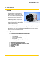
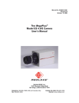
The MegaPlus ES 1020 is a high-resolution CCD
camera provides real time digital imaging and is
capable of capturing up to 48 frames per second
with a spatial resolution over one million pixels. The
ES 1020 version of Redlake’s ES Series is lighter and
more compact than its predecessors and uses the
latest technology including Camera Link (CL).
The MegaPlus ES 1020 uses an interline transfer
CCD with progressive scan readout and
microlenses, which provides good sensitivity
without sacrificing speed. The camera outputs 8- or
10-bit digital images with up to 1024 levels of gray
resulting in high contrast detail.
The camera also features a built-in electronic shutter with exposure times as short as 35 microseconds
for maximum flexibility and performance when capturing images of fast moving objects. The triggered
double-exposure mode captures two images just microseconds apart.
With outstanding speed and resolution, the MegaPlus ES 1020 is ideal for machine vision, PIV, semiconductor and electronic inspection, microscopy, and other applications requiring cost-effective, realtime image capture in a compact efficient package.
Camera Features
•
Kodak interline transfer CCD sensor – Monochrome or Color
o
o
o
o
o
o
o
o
•
•
•
•
•
Front Illuminated Interline Architecture
KAI-1020: 1004(H) x 1004(V) Photosensitive Pixels
7.4 Square Pixel Size
Progressive Scan (Non Interlace)
Electronic Shutter
Dual Output Shift Registers (Left/Right or Odd/Even))
Anti-blooming Protection
Low Smear (0.01% with micro lens)
Camera Link (CL) interface base configuration
Trigger is controlled through the CC1 Camera Link channel
Single 12V Power supply
Low Power ( < 4.2 Watts )
Compact size
Redlake MASD, Inc.
Page 4
91000134-001 Rev. A
MegaPlus ES 1020 User’s Manual
2. Setup Guide
Before you Begin
Before you begin to setup your MegaPlus® ES-1020, please verify that the package you received
contains all the components listed on your packing slip.
Minimum Package Contents
(1) ES-1020 Camera
(1) Mounting Bracket
(1) CD with Camera Control Software & User’s Manual
Optional/Addition Items
(1) Camera Link Cable with MDS-26 connectors
Camera Link cable must be purchased separately.
(1) Strobe/Trigger/Power
Also available for purchase separately is a Strobe/Trigger/Power Accessory cable.
(1) Power Adapter
The ES 1020 requires the use of a Power Adapter with 110/220V Cords which must be purchased
separately through Redlake MASD, Inc.
Lens(es)
Because every application is different with varying focusing and field of vision requirements,
the ES 1020 is not shipped with lenses. They must be purchased separately.
Minimum/Recommended System Requirements
Minimum
• Pentium II, 233 MHz Processor
• At least 32 MB of Ram, 64 MB Recommended
• Frame Grabber Board with Camera Link Adapter (base configuration)
• 20 MB of Hard drive disk space available
Operating System Requirements
Once you have selected your PC, ensuring that it meets the minimum configuration for your
application, make sure that it is running a Microsoft Windows™ operating system, Windows XP,
Windows 2000 Pro (service pack 2) or Windows NT 4.0 or later.
Redlake MASD, Inc.
Page 5
91000134-001 Rev. A
MegaPlus ES 1020 User’s Manual
Software Installation
The ES 1020 Camera Control Software provides all camera control functions, and is designed to be run
concurrently with the image acquisition software that is provided with the Camera Link frame grabber
board installed on the host PC.
A few basic steps are necessary to install the software needed to control both the frame grabber board
and the camera.
CameraLink Frame Grabber Board Image Acquisition Software
The ES 1020 is designed to work with frame grabber boards adhering to Camera Link standards. Before
setting up the camera, ensure that the frame grabber board and software have been installed. Please
follow the instructions outlined in the frame grabber manufacturer’s documentation.
NOTE: Frame Grabber Boards currently certified to operate with the ES 1020 Control Software at the time of this
printing include:
• Coreco Imaging PC-CamLink
• Matrox Meteor II Camera Link
Launch the Frame Grabber Image Acquisition software and ensure that it is configured properly to
communicate with the ES 1020.
ES 1020 Camera Control Software
1.
Insert the Redlake MegaPlus ES 1020 software CD. The software install process should begin
automatically. If it does not, browse the CD and double-click Setup.exe. The install wizard with
guide you through the rest of the setup process.
Redlake MASD, Inc.
Page 6
91000134-001 Rev. A
MegaPlus ES 1020 User’s Manual
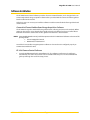
Hardware Setup
Connect Camera Link Cable
1.
Connect one end of the Camera Link cable to the ES 1020, and the other
end to the Frame Grabber board installed in the PC.
Connect Power Cable
1.
First, connect the Power Cable (male end) to the Power Adapter.
2.
Connect the Power Cable to the camera’s Power connector. Connect
the power adapter to a standard wall outlet using one of the power
cables provided.
NOTE: Line up the “red dots” ( ) to ensure proper alignment of the cable
and connector.
Connect Optional Strobe/Trigger/Power Cable
1.
First, connect the Power Cable (male end) to the LEMO connector on the Power Adapter.
2.
Then, connect to the female end of the Power Cable to the camera’s Power connector.
3.
Finally, connect the power adapter to a standard wall outlet using one of the power cables provided.
4.
When the camera is receiving power, the GREEN Power LED will be on. When the YELLOW Activity LED is
blinking, it indicates the micro processor is ready to receive a command.
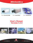
NOTE: The camera is
designed with mounting
holes on all four outside
planes of the camera body,
for attaching the mounting
bracket. To ensure proper
camera orientation when
attaching the mounting
bracket, pay special
attention to the small arrow
and the word “up” located
on the serial number plate
on the rear of the camera.
Redlake MASD, Inc.
Page 7
91000134-001 Rev. A
MegaPlus ES 1020 User’s Manual
3. Camera Control Software User’s Guide
The ES 1020 Camera Control Software is
designed to run concurrently with image
acquisition software. Both programs must
be installed separately. (See Software
Installation.)
Launch Camera
Control Software
To launch the ES 1020 Camera
Control Software:
1.
Double-click on the Redlake icon on
your desktop, or click on the ES 1020
Camera Control link located in your
start menu.
2.
Select the correct “Camera Link DLL”
from the drop down when prompted.
This is the DLL that corresponds to the
Camera Link Frame Grabber board
installed.
NOTE: Launch the Camera Control Software and
select the correct Camera Link DLL
BEFORE launching the Frame Grabber
Board Image Acquisition software.
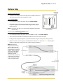
Configure Camera Operating
Mode Settings
The Graphical User Interface offers access to all the programmable camera functions. The various
regions of the GUI are outlined below.
REFRESH Button
This button is for updating the GUI to reflect what the camera is set to. It is used whenever the camera
and the software lose synchronization. The following is an example of how the GUI can lose
synchronization:
1.
2.
3.
4.
Camera powered on
Software started
Camera settings changed in the software
Camera powered off, then on again
At this point, since the camera’s settings have not been saved to EEPROM, the software reflects the
settings the camera was set to prior to being powered off. Press REFRESH to update the GUI to reflect
the camera’s actual settings.
If the camera looses communication with the frame grabber board, clicking the REFRESH button with
cause the Select Camera Link DLL dialogue box to re-open prompting the user to re-establish
communications.
Redlake MASD, Inc.
Page 8
91000134-001 Rev. A
MegaPlus ES 1020 User’s Manual
Menu Options
File Menu contains the “Exit”
Tools Menu
• Save Current State to EEPROM saves current settings to the cameras firmware.
• Restore to Last Saved State restores all Operating Modes to the most recently saved settings.
• Select Camera Link DLL opens a pop-up dialogue window to allow the user to select or
change the Camera Link DLL.
NOTE: As with any firmware update, the update process must be allowed to finish completely without
interruption to avoid firmware corruption. Therefore it is recommended that the user wait a minimum of
10 seconds after the selecting the Save Current State to EEPROM command.
View Menu allows the user to enable or disable the Always On Top option, enabled indicated with a
check () mark.
About Menu displays software application release date and build information.
Operating Modes
Trigger Modes
• Free Run The camera continuously takes images at its mode dependent frame rate. See Free
Run Mode.
• Digital Test Pattern appears as a gray ramp with a white grid overlaid on it. The test pattern is
very useful in hunting down problems with cables and captures cards.
• Crosshair on may be enabled when the camera is in Single Tap Mode; when enabled, white
vertical and horizontal lines are overlaid on the video image converging at the center.
• Triggered Prog Exposure (TPE) Is used when a predetermined triggered exposure is required.
Exposure time (sec) is set by “sliding” pointer along the slider bar. Setting ranges from 0.000 to
0.1216 (sec).
• Triggered Manual Exposure (TME) works exactly as the TPE mode with the following
exception; the exposure may be extended by keeping the external trigger line asserted.
• Triggered Double Exposure works exactly as the TPD mode with the following exception; an
additional frame is read out from the sensor.
• Trigger: Programmed Exposure (sec) Slider Setting ranges from 0.000 to 0.1216 (sec). The
numbers shown in the yellow<alt> text indicate a value for that position on the slider within an
arbitrary scale.
• Trigger Polarity includes radio buttons to select either Positive or Negative.
Camera Temperature
• Non-editable text field displaying the current camera temperature.
NOTE: Camera should be shielded from external heat sources, and should not be allowed to exceed 65°C.
Data Formatting
• Data Width includes radio buttons to allow the user to select 8 Bit or 10 Bit Mode
• Output includes radio buttons to allow the user to select Single Tap or Dual Tap Mode.
• Horizontal Tap Flip includes radio buttons to allow the user to select Normal or Flip Mode
• Bit Flip includes radio buttons to allow the user to select Normal or Flip Mode
Gain & Exposure
• Free Run Exposure allows the user to set Single Tap and Dual Tap Exposure using individual
sliders with ranges from 0.393 t0 1023. The number shown in the yellow<alt> text indicates a
value for that position within an arbitrary scale.
• Gains includes 4 radio buttons allowing the user to select Gain values of: 1, 2, 4 and 8.
Redlake MASD, Inc.
Page 9
91000134-001 Rev. A
MegaPlus ES 1020 User’s Manual
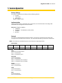
Scan Control
• Partial Scan includes Radio buttons to Enable or Disable Partial Scan, a Start Line Slider, and a
Stop line Slider with text displays of numeric setting.
Scan Control: example of Partial Scan
Binning is a special readout mode where the camera 'bins' or combines pixel data. The effect of
binning is that the image will have lower resolution but higher SNR, and by using vertical binning the
image readout speed is improved. The ES 1020 cameras implement horizontal and vertical binning as
separate controls.
•
Vertical includes 5 radio buttons to allow the user to select Vertical Binning modes including:
V Bin x 1, V Bin x 2, V bin x 4, V Bin x 8, V Bin x 16.
•
Horizontal includes 3 radio buttons to allow the user to select Horizontal Binning modes
including: H Bin x 1, H Bin x 2, H Bin x 4.
Redlake MASD, Inc.
Page 10
91000134-001 Rev. A
MegaPlus ES 1020 User’s Manual
4. ES 1020 Camera Operations Manual
The following section describes in detail the function of the cable connectors and LEDs located on the
rear panel of the ES 1020.
Camera
LED’s
There are two LED's on the back of the ES 1020
Camera.
A solid GREEN Power LED indicates that the
camera is receiving 12V DC.
A blinking YELLOW Activity LED indicates the
microprocessor is ready to receive a command.
Cables and Mating Connectors
Camera Link
Located in the center of the rear panel of the camera is the CameraLink connector. A similar connector
is located on the frame grabber board, and should be accessible on the back of the PC. The CameraLink
cable has (2) MDR-26 connectors. Both ends of the cable are the same.
Power
The ES 1020 receives power through the Power Connection also located
on the rear panel. This is a 4 pin LEMO™ connector.
PIN 1 = GND
PIN 2 = +12V DC at 400mA*
PIN 3 = Strobe out (Open Collector)
PIN 4 = Trigger echo output (3.3V through 1K resistor)
Redlake MASD, Inc.
Page 11
91000134-001 Rev. A
MegaPlus ES 1020 User’s Manual
5. Camera Operation
Factory Settings
The camera is configured at the factory with the following defaults:
• Free Run
• 2 Tap output
• 10 bit output
Negative Trigger Polarity
Implementation
Camera communication is accomplished via asynchronous serial communication according to EIA
Standard RS 232 C through the Camera Link cable.
Data rate: Full Duplex, 9800 bps.
• 1 START bit
• 8 DATA bits – The LSB (D0) is transferred first
• 1 STOP bit
• No parity
Protocol
The camera is controlled through command packets. The camera is considered a slave device and
never generates data without a read request. The data packet formatting is described in detail below.
NOTE: The checksum is calculated only on the 4 ascii characters comprising the Data.
Data Packets
1 ascii
character
2 ascii
characters
2 ascii
characters
2 ascii
characters
4 ascii
characters
2 ascii
characters
1 ascii
character
1 ascii
character
Start
Command
Target
Index
Data
Check
End
Ack/Nack
Start
Indicates the Start of the frame
Size = 1 ascii character
Value = 123 Decimal (ascii { )
Command
Command descriptor
Size = 1 ascii character
Value = 114 Decimal (ascii r ) for Read
Value = 119 Decimal (ascii w ) for Write
Target
Command descriptor
Size = 2 ascii characters
Index
Command descriptor
Size = 2 ascii characters
Data
The data transferred
Size = 4 ascii characters
Redlake MASD, Inc.
Page 12
91000134-001 Rev. A
MegaPlus ES 1020 User’s Manual
Check
Data Checksum - calculated on DATA Only
Size = 2 ascii characters - Intel-Standard - two’s compliment of sum.
Example1: Data = 2002, checksum = lower byte of (0x100 – (0x20 + 0x02)) = 0xde
Example2: Data = 0000, checksum = lower byte of (0x100 – (0x00 + 0x00)) = 0x00
Example3: Data = fef0, checksum = lower byte of (0x100 – (0xfe + 0xf0)) = 0x12
End
Indicates the End of the frame
Size = 1 ascii character
Value = 125 Decimal (ascii } )
Ack/Nack
Positive acknowledge - Negative acknowledge
Size = 1 ascii character
Ack Value = 33 Decimal (ascii ! )
Nack Value = 63 Decimal (ascii ? )
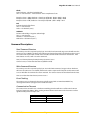
Command Descriptions
Read Command Structure
The camera parses the sequence byte by byte. An invalid read command, target or index will cause the
camera to issue an NACK. The Host (You) will generate dummy data with a valid checksum then an end.
The camera will respond with an ACK and re send the command with valid data and checksum. If the
Host detects an error, it will re issue the command.
Host {r tt ii dummy dummy dummy dummy cc} camera issues !
Camera issues {r tt ii data data data data cc} (NOTE no ACK)
Write Command Structure
The camera parses the sequence byte by byte. An invalid write command, target, index or checksum
will cause the camera to issue a NACK, otherwise the write sequence will complete and the camera will
issue an ACK after the command has been executed. The camera receives the checksum from the Host.
Host {w tt ii data data data data cc} camera issues !
Error Checking
The camera parser is character by character and will respond with an immediate NACK if any
unrecognised command, target, index or checksum occurs.
Communication Timeouts
The camera micro controller uses a hardware watchdog timer that will time out if the time between
bytes are longer than 200ms. When sending command frames to the camera the host must not have
significant delays between bytes sent.
Normal
Power up BIT
Initiated BIT
Power up
Redlake MASD, Inc.
< 50ms
< 4s
< 2s
< 6s
Page 13
91000134-001 Rev. A
MegaPlus ES 1020 User’s Manual
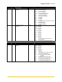
Camera Mode Command Table 1.1
NOTE: It is recommended to issue a soft reset command after writing to 0400 – 0405. The soft reset command is
{w030b000000}. This will ensure that the internal state machine is reset for the new mode.
Target
Index
Description
Operation
Modes
04
00
Camera Control
Single Tap Enable
Write
04
01
Tap Flip
Write
04
02
Bit Flip
Write
04
03
Trigger Mode
Write
04
04
Test Pattern
Write
04
05
Binning
Write
04
06
Gain Select
Write
0x0000 = Dual Tap
0x0001 = Single Tap
0x0000 = Normal
0x0001 = Flip
0x0000 = Normal
0x0001 = Flip
0x0000 = Free Run
0x0001 = Trigger Prog Exposure
0x0002 = Trigger Manual Exposure
0x0003 = TDE
0x0000 = Normal Video
0x0001 = Test Pattern
0x0000 = Disable all binning
0x0001 = H bin x 2
0x0002 = V bin x 2
0x0003 = H & V bin x 2
0x0004 = H bin x 4
0x0005 = H bin x 1
0x0006 = V bin x 1
0x0008 = V bin x 4
0x000c = H & V bin x 4
0x0001 = 1
0x0002 = 2
0x0004 = 4
0x0008 = 8
04
04
07
08
Camera Temperature
Camera actual exposure
10 bit number
Read
Read/Write
low speed
version
ES 1020
Read/Write
Low speed
version
ES 1020
Write
04
09
Partial Scan Enable
04
04
04
0a
0b
0c
04
0d
Partial Scan Start Line
Partial Scan Stop Line
Micro IBIT initiate – IBIT resets
the timing generator, tests ADC
read / writes and EEPROM read
/ writes and reloads camera
configuration and sets modes.
Clear bit status register prior to
execution and check mode
registers 1 and 2 and bit status
register 1 after executing
Bit Width
Write
04
0e
Trigger Polarity
Write
04
0f
Crosshair Enable
Write
04
10
2x pixel clock Enable
(OEM mode)
Write
Redlake MASD, Inc.
Read/Write
Read/Write
Write
Page 14
0x0000 =110µsec
0x03ff = 76.32msec (single tap mode)
0x0000 =83µsec
0x03ff = 43.9msec (dual tap mode)
0x0000 = Disable
0x0001 = Enable
0x0010 to 1200
Start line + 1 to 1200
0x0000 = Clear Bit Status Register
0x0001 = IBIT
0x0000 = 10 bit mode
0x0001 = 8 bit mode
0x0000 = negative trigger pulse
0x0001 = positive trigger pulse
0x0000 = disable crosshair
0x0001 = enable crosshair
0x0000 = disable 2x pixel clock
0x0001 = enable 2x pixel clock
91000134-001 Rev. A
MegaPlus ES 1020 User’s Manual
Camera Mode
05
00
Camera mode status
Register 1
Read
05
01
Camera mode status
Register 2
Read
06
00
Camera BIT Status
Register 1
Bit 15
Bit 14
Bit 13
Bit 12
Bit 11
Bit 10
Bit 9
Bit 8
Bit 7
Bit 6
Bit 5
Bit 4
Bit 3
Bit 2
Bit 1
Bit 0
Bit 15
Bit 14
Bit 13
Bit 12
Bit 11
Bit 10
Bit 9
Bit 8
Bit 7
Bit 6
Bit 5
Bit 4
Bit 3
Bit 2
Bit 1
Bit 0
1 = v bin x 4 enabled
1 = h bin x 4 enabled
1 = v bin x 2 enabled
1 = h bin x 2 enabled
1 = Positive trigger polarity
1 = Test Pattern Enabled
1 = Partial Scan Enabled
1 = ten bit mode enabled
1 = 8 x Gain
1 = 4 x Gain
1 = 2 x Gain
1 = 1 x Gain
1 = Trigger programmed exposure enabled
1 = Bit flip enabled
1 = Tap flip Enabled
1 = Single Tap Enabled
not used
not used
not used
not used
not used
not used
not used
not used
not used
not used
not used
not used
not used
1 = Trigger double exposure enabled
1 = IBIT complete
1 = Trigger manual exposure enabled
Bit 15
Bit 14
Bit 13
Bit 12
Bit 11
Bit 10
Bit 9
Bit 8
Bit 7
Bit 6
Bit 5
not used
not used
not used
not used
not used
not used
1 = CBIT fail
1 = IBIT fail
1 = Timing generator failed to configure
1 = Watchdog timer timeout
1 = Camera loaded from EEPROM
(0 = ROM)
1 = EEPROM failed read/write test
1 = Temp sensor failed read/write test
1 = B A to D failed read/write test
1 = A A to D failed read/write test
1 = Timing Generator failed read/write test
Camera BIT status
Read
Bit 4
Bit 3
Bit 2
Bit 1
Bit 0
Redlake MASD, Inc.
Page 15
91000134-001 Rev. A
MegaPlus ES 1020 User’s Manual
Camera Mode Descriptions
The Camera operates in one of four modes; free run, trigger programmed exposure, trigger manual
exposure and trigger double exposure. The mode is selected by writing the appropriate command
from the table above.
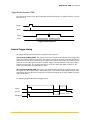
Free Run Mode
The camera continuously takes images at its mode dependent frame rate. See Tables Appendix E. The
camera generates all synchronous timing including FVAL, LVAL, DVAL and pixel data and clocks.
In free run mode (FRM) the camera exposure is calculated in horizontal line times. Thus exposure steps
are equal to the camera horizontal line time plus a small overhead for the image transfer into the
internal vertical storage CCD.
Trigger
Strobe
FVAL
LVAL
Data
Free Run Mode
Redlake MASD, Inc.
Page 16
91000134-001 Rev. A
MegaPlus ES 1020 User’s Manual
Trigger Exposure Modes
The ES 1020 triggered exposure modes (TEM) work differently from the free run mode in that the TEM is
based on the pixel clock (divided by 64) as opposed to the line timing. There are separate exposure
registers for the TEM and FRM.
NOTE: Externally triggering the camera may only be done via the Camera Link interface. The Strobe
and Trigger cables provide OUTPUT signals only.
Trigger Programmed Exposure (TPE)
The TPE mode is used when a predetermined triggered exposure is required. The exposure time is
programmed into the TPD (Transfer Pulse Delay) register and the TPE mode is set. In this mode, the
camera enters a continuous flush mode (CFM) while waiting for the external trigger line to be activated.
The external trigger line is sampled and if active, the camera begins an exposure as set by the TPD
register. After the exposure period is complete, the image is clocked out. As the exposure is started, the
external strobe signal is asserted. The external strobe signal can be used to activate a strobe light.
Trigger*
Strobe
Programmed Exposure (PE)
FVAL
Data
Trigger Programmed Exposure Mode
Trigger Manual Exposure (TME)
This mode works exactly as the TPE mode with the following exception; The exposure may be extended
by keeping the external trigger line asserted. Once the external trigger is de-asserted the ES 1020
completes the programmed exposure (PE) as defined by the TPD register value. To control the exposure
in this mode it is recommended that the TPD register be set as small as possible (0x006) so that the
camera executes only a very short-programmed exposure after the de-assertion of the external trigger.
Trigger*
Manual Exposure
Strobe
(PE)
FVAL
Data
Manual Shutter Mode
•
Note that the trigger polarity can be set via command
Redlake MASD, Inc.
Page 17
91000134-001 Rev. A
MegaPlus ES 1020 User’s Manual
Trigger Double Exposure (TDE)
This mode works exactly as the TPD mode with the following exception; an additional frame is read out
from the sensor.
Trigger
Strobe
FVAL
Data
Triggered Double Exposure
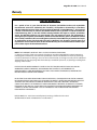
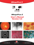
Internal Trigger timing
The trigger timing is based upon three user programmable registers.
(a) Transfer Pulse Delay (TPD): This register sets the time delay from the detection of the trigger pulse
to the start of the transfer pulse sequence. The register is used to set the delay in increments of 2112ns.
Note that the transfer pulse sequence requires a front pedestal, then the transfer pulse and then a back
pedestal. Thus the TPD register cannot be used flash trigger sequences below the pedestal size (40us)
without external timing. The range that TPD can be set to is 6 to 65535 dec. (0001 to FFFF hex). This
results in a usable delay range from 30us to 138ms.
(b) Transfer Pulse Width (TPW): This register sets the width of the photodiode to VCCD transfer pulse.
The register is used to set the width in increments of 33ns. This results in a pulse width of 33ns to 20us.
Note that the drive circuitry of the transfer pulse is limited to minimum pulse of about 800ns (A register
setting of 0010 hex).
The following diagram illustrates the trigger timing:
Trigger
Transfer
Pedestal = 31us
SUB (Erase)
Redlake MASD, Inc.
Page 18
91000134-001 Rev. A
MegaPlus ES 1020 User’s Manual
6. Maintenance, Technical Support and Warranty
Routine Maintenance
There are no user serviceable parts inside the camera. The camera must be returned to the factory for
repair if a malfunction occurs.
The lens and the sensor cover glass should only be cleaned using dust-free compressed air.
Clean the exterior of the camera with a soft, dry, lint-free cloth. For stubborn dirt, the cloth may be
dampened with a mild soap solution.
Technical Support
Telephone: 1-800-854-7006 (USA and Canada only)
Outside the USA: (858) 481-8182
Fax: (858) 350-9380
Internet: www.redlake.com
Mailing Address:
Redlake MASD, Inc., 11633 Sorrento Valley Road, San Diego, California 92121-1010
For international customers, please contact your authorized Redlake MASD, Inc. Distributor for
information. You may also contact one of the below listed service centers:
Roper Scientific BV (Europe, Middle East and Africa):
Telephone: (31) 347 32 4989
Fax: (31) 347 32 4979
Internet: [email protected]
Mailing Address:
Roper Scientific BV, Ir. D.S. Tuijnmanweg 10, 4131 PN Vianen, Nederland
Nippon Roper KK, Japan: (For Japan Only)
Telephone: 011-(81) -3-5639 -2770
Fax: 011-(81) -–3 -–5639 -2775
Internet: [email protected]
Mailing Address:
Nippon Roper KK, 6F Sakurai Building, 2 8 19 Fukagawa Koto Ku, Tokyo, 135-0033, Japan
Redlake MASD, Inc.
Page 19
91000134-001 Rev. A
MegaPlus ES 1020 User’s Manual
Warranty
LIMITED WARRANTY
For a period of one (1) year from the date of shipment, the Redlake Product and any Redlake
manufactured accessories (collectively the “Product”), shall perform substantially in accordance
with the material provisions of the user manual for the Product (“Limited Warranty”). If, because of
a defect in workmanship or material, the Redlake Product fails to perform in accordance with the
Limited Warranty, then, as the sole available remedy, Redlake shall repair or replace, at Redlake’s
option, the Redlake Product or any part thereof. The sole remedy of repair and replacement is
contingent upon shipment of the Product, within the Limited Warranty period, to Redlake’s United
States facility. Redlake shall have no obligation under this Limited Warranty to provide local repair
or replacement services for the Product, but will, at Redlake’s sole discretion, provide repair and
replacement service under the terms of the Limited Warranty at its non-United States facilities upon
prior written request of the Product Purchaser.
NOTE: THIS WARRANTY DOES NOT APPLY TO THE FOLLOWING CONDITIONS:
(1) damage caused by a failure to operate the Product in accordance with Redlake’s written instructions,
including, but not limited to, environmental specifications listed in the Redlake user manual; (2) damage
caused by accidental user damage, misuse or abuse of the Product; (3) damage caused by the unauthorized
attempted repair of or tampering with the Product by non-Redlake personnel; or (4) damage resulting from
shipping of the Product.
EXCEPT FOR THE LIMITED WARRANTY STATED IN THIS SECTION, REDLAKE DISCLAIMS ANY AND ALL
WARRANTIES, EXPRESS OR IMPLIED, INCLUDING BUT NOT LIMITED TO, ANY WARRANTY OF
MERCHANTABILITY, NON-INFRINGEMENT, OR FITNESS FOR A PARTICULAR PURPOSE, REGARDING THE
REDLAKE PRODUCT OR ANY PART THEREOF.
IN NO EVENT SHALL REDLAKE BE LIABLE FOR ANY INCIDENTAL, CONSEQUENTIAL OR SPECIAL DAMAGES,
INCLUDING WITHOUT LIMITATION LOSS OF BUSINESS OR PROFITS, EVEN IF REDLAKE RECEIVES NOTICE IN
ADVANCE THAT THESE KINDS OF DAMAGES MIGHT RESULT, NOR SHALL REDLAKE’S AGGREGATE
CUMULATIVE LIABILITY TO THE PRODUCT PURCHASER, PRODUCT RECIPIENT, OR PRODUCT CUSTOMER,
PURSUANT TO ANY AND ALL CLAIMS AND LEGAL THEORIES (INCLUDING NEGLIGENCE AND BREACH OF
CONTRACT), EXCEED THE ORIGINAL COST OF THE PRODUCT PAID TO REDLAKE BY THE ORIGINAL
PURCHASER OF THE PRODUCT.
Redlake MASD, Inc. 11633 Sorrento Valley Road, San Diego, California 92121-1010
(Redlake MotionCentral and MotionXtra are trademarks.)
Redlake MASD, Inc.
Page 20
91000134-001 Rev. A
MegaPlus ES 1020 User’s Manual
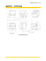
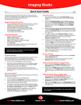
Appendix A Case Drawings
*units in inches
ES 1020 Camera Dimensions
\
Redlake MASD, Inc.
Page 21
91000134-001 Rev. A
MegaPlus ES 1020 User’s Manual
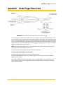
Appendix B Strobe/Trigger/Power Cable
WARNING: Always check the pin out of a custom cable before using it!
The strobe/trigger accessory cable enables access to the camera's output signals located on pins 2 and
3 on the camera power connector. These two outputs provide TTL level trigger pulses. The output signal
on pin 3 is generated from with in the camera and used for firing a strobe light. The output signal on pin
2 is used to monitor the trigger signal that arrives to the camera from the Camera Link cable. The trigger
output signal on pin 2 is pass-through of the incoming trigger. If no trigger signal is sent from the frame
grabber, no signal will be present on pin 2.
NOTE: Externally triggering the camera may only be done via the Camera Link interface. The Strobe
and Trigger cables provide OUTPUT signals only.
Terminate unattached female BNC connectors with 50Ω terminators.
To connect the strobe/trigger accessory cable:
Unplug the power connector from the camera if already attached.
Insert the MALE LEMO® connector on the strobe/trigger accessory cable into the camera's FEMALE
LEMO® power connector.
Attached the FEMALE end of the strobe/trigger cable to the MALE LEMO® connector located on the
power adapter. At this point, the Trigger Out and Strobe Out BNC cables are routing their respective
signals out of the camera.
Redlake MASD, Inc.
Page 22
91000134-001 Rev. A
MegaPlus ES 1020 User’s Manual
Appendix C
Advanced Functions
Timing Generator Control Register 1
15
14
13
12
11
10
9
8
TRIGGER
POL
PARTIALSC
AN EN
FLIP BITS
SINGLE TAP
TRIGGER
ENABLE
TME
ENABLE
TDE
ENABLE
RESERVED
7
6
5
4
3
2
1
0
TEST
PATTERN
ENABLE
TG SOFT
RESET
8 Bit CL
output
TAP FLIP
VBIN
4/2
VBIN
ENABLE
HBIN
4/2
HBIN
ENBLE
• TRIGGER POL(ARITY)
Set to 0 for negative trigger pulse
Set to 1 for positive trigger pulse
• PARTIAL SCAN ENABLE: Single tap output mode for testing
Set to 1 to enable operation
• FLIP BITS: Flips data bits from msb to lsb
Set to 0 to enable msb in bit 0
Set to 1 to enable lsb on bit 0
• SINGLE TAP: Single/Dual tap readout selection
Set to 1 to enable single tap operation
Set to 0 to enable dual tap operation
• TRIGGER ENABLE: Select Trigger mode of operation
Setting this bit to 1 will cause the TG to enter the external trigger mode
• MANUAL EXPOSURE: Manual trigger mode selection
Set to 1 to enable single tap operation
Set to 0 to enable dual tap operation
• TDE ENABLE: Trigger Double Exposure Enable
Set to 1 to enable TDE mode
Set to 0 to disable TDE mode
• TEST PATTERN ENABLE:
Setting this bit to 1 will cause the TG to output a fixed gray pattern with grid overlay.
Set to 0 to disable the test pattern
• TG SOFT RESET: Timing Generator State Machine Reset
Set to 1 to re-initialize TG state machine
Set to 0 to resume normal operation
• 8 Bit CL Output (SINGLE TAP ONLY)
Setting this bit re maps the camera link output to 8 bits per tap.
The 8 most significant bits of the ADC are used.
• TAP FLIP
Setting this bit to 1 will cause the TG to flip taps.
Redlake MASD, Inc.
Page 23
91000134-001 Rev. A
MegaPlus ES 1020 User’s Manual
• VBIN 4/2: Vertical bin x 2 or x 4
Set to 1 to enable VBIN x 4
Set to 0 to enable VBIN x 2
• VBIN ENABLE
Set to 0 to enable normal operation
Set to 1 to enable vertical binning
• HBIN 4/2: Horizontal bin x 2 or x 4
Set to 1 to enable HBIN x 4
Set to 0 to enable HBIN x 2
• HBIN ENBLE
Set to 0 to enable normal operation
Set to 1 to enable horizontal binning
Exposure and Control Register 2
15
14
13
12
11
10
9
8
CR2_3
CROSS
HAIR
ENABLE
LONG_VBI
N
LVDS
CLOCK x 2
EXP BIT 11
EXP BIT 10
EXP BIT 9
EXP BIT 8
7
6
5
4
3
2
1
0
EXP BIT 7
EXP BIT 6
EXP BIT 5
EXP BIT 4
EXP BIT 3
EXP BIT 2
EXP BIT 1
EXP BIT 0
•
EXP BIT 0 - 11
Manual Exposure
•
LVDS CLOCK x 2 (note: set to 0 for normal operation, set to 1 for 2x LVDS clock)
Set to 0 to
Set to 1 to
•
LONG V BIN
Set to 0 to disable V bin x 8 and 16
Set to 1 to enable V bin x 8 and 16 (Choose via VBIN x 4/2)
•
CROSS HAIR ENABLE (note: use single tap mode for cross hair alignment)
Set to 0 to disable cross hair overlay
Set to 1 to enable cross hair overlay
•
CR2_3
Redlake MASD, Inc.
Page 24
91000134-001 Rev. A
MegaPlus ES 1020 User’s Manual
02
02
02
02
02
02
02
02
02
02
02
00
01
02
03
04
05
06
07
08
09
0a
Timing Generator
TG Timing
TG Control
TG Partial Scan Start
TG Partial Scan Stop
Transfer Pulse Delay
Transfer Pulse Width
TG Firmware Revision
TG Invert Signals
Reserved
Reserved
TG Exposure
Memory Management
Save Camera State to User
EEPROM
Read/Write
Read/Write
Read/Write
Read/Write
Read/Write
Read/Write
Read
Read/Write
0x3b54
0x0000
300
900
Read/Write
1150
Write
(dummy
data, correct
checksum)
Read (end
and ack only)
Write
(dummy
data, correct
checksum)
Read (end
and ack only)
Read (end
and ack only)
Read
Write
NA
Write
0x0000 = Save Gain =1 to user and
factory
0x0001= Save Gain = 2 to user and
factory
0x0002=Save Gain = 4 to user and
factory
0x0003 = Save Gain = 8 to user and
factory
0x0000 = Save un binned timing to
factory and user EEPROM
0x0001 = Save hbinx2 tuning to
factory and user
0x0002 = save hbinx4 tuning to
factory and user
03
00
03
01
03
02
03
03
03
04
03
03
05
06
03
07
03
09
Save tuning data to Factory
and User EEPROM
Write
03
03
0a
0b
INIT camera no Xilinx reload
Soft INIT Xilinx
Write
Write
Load User EEPROM to Camera
State
Save Camera State to Factory
EEPROM
Load Camera State from
Factory EEPROM
Load Current Camera State
from ROM
Read EEPROM Location
Reload Xilinx and restart
camera
Save Tap Matching Array to
Fact and User EEPROM
Redlake MASD, Inc.
Page 25
0x0000
NA
NA
NA
NA
0x0000 = Normal operation
0x0001 = Init state machines
91000134-001 Rev. A
MegaPlus ES 1020 User’s Manual
05
05
00
01
Camera Mode
Camera mode status register 1
Camera mode status register 2
06
06
00
01
Camera BIT status
Camera BIT Status Register 1
Camera BIT Status Register 2
07
07
07
07
07
00
01
02
03
04
07
07
05
06
Camera Configuration
Camera Model
Camera Revision
Camera Serial Number
Micro firmware version
Timing Generator firmware
version
Overall Software Version
Clear EE Init flag
Redlake MASD, Inc.
Read
Read
Read
Read
Read/Write
Read/Write
Read/Write
Read
Read/Write
Read/Write
Write
Page 26
91000134-001 Rev. A
MegaPlus ES 1020 User’s Manual
Appendix D Camera Timing
ES 1020 Timing Specifications
Free Run Electronic Exposure
Master Clock
Frames/Sec
One Tap
34.4Mhz - 29ns period
28.37
Two Tap
34.4Mhz - 29ns period
48.83
H Active Pixels
H Count
H Active Time
H Sync Time
H Line Time
1004
1194
29.24us
5.561us
34.9us
502 x 2 Taps
692
14.65us
5.561us
20.21us
V Active Lines
V Count
V Active Time
V Sync Time
V Frame Time
1004
1010
34.98ms
269.3us
35.24ms
1004
1010
20.31ms
167.1us
20.48ms
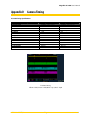
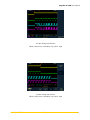
Free Run Timing
Yellow = FVAL, Green = LVAL, Blue = Tap L, Red - Tap R
Redlake MASD, Inc.
Page 27
91000134-001 Rev. A
MegaPlus ES 1020 User’s Manual
Free Run Timing: Start of Frame
Yellow = FVAL, Green = LVAL, Blue = Tap L, Red - Tap R
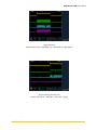
Free Run Timing: End of Frame
Yellow = FVAL, Green = LVAL, Blue = Tap L, Red - Tap R
Redlake MASD, Inc.
Page 28
91000134-001 Rev. A
MegaPlus ES 1020 User’s Manual
Triggered Timing
Yellow = FVAL, Green = LVAL, Blue = Tap L data bit, Red - Tap R data bit
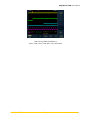
Triggered Timing: Start of Frame
Yellow = FVAL, Green = LVAL, Blue = Tap L, Red - Trigger
Redlake MASD, Inc.
Page 29
91000134-001 Rev. A
MegaPlus ES 1020 User’s Manual
DVAL Timing: Binning off
Yellow = FVAL, Green = LVAL, Blue = Tap L, Red - DVAL
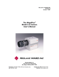
DVAL Timing: 2X Horizontal Binning
Yellow = FVAL, Green = LVAL, Blue = Tap L, Red - DVAL
Redlake MASD, Inc.
Page 30
91000134-001 Rev. A
MegaPlus ES 1020 User’s Manual
DVAL Timing: 4X Horizontal Binning
Yellow = FVAL, Green = LVAL, Blue = Tap L, Red - DVAL.
Redlake MASD, Inc.
Page 31
91000134-001 Rev. A