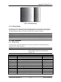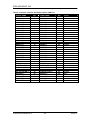
1
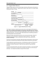
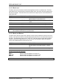
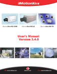
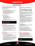
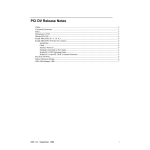
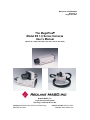
Manual No. 91000064-004
Revision A
August 29, 2001
The MegaPlusâ
Model ES 1.0 Series Cameras
User’s Manual
(Models ES 1.0,ES 1.0/PIV, ES 1.0/SC, ES 1.0/10 Bit, ES 1.0/TH)
Redlake MASD, Inc.
11633 Sorrento Valley Road
San Diego, California 92121-1097
Telephone: 800-854-7006 (USA and Canada only)
Fax: 858-481-6254.
Outside the USA: 858 481-8182
Internet: www.redlake.com
REDLAKE MASD, INC.
List of Manual Revisions
User’s Manual – Model ES 1.0 Series, Part Number 91000064-002
Revision
Date
A
08-29-01
EO No.
Notes
Reissued to reflect Redlake MASD, Inc. change, new
flexible cable for tethered head, new format, and general
cleanup.
RELATED DOCUMENTS
MegaPlus Model ES 1.0 Remote Control Panel User’s Manual, Part #91000074-001
FCC DECLARATION OF CONFORMITY
This equipment has been tested and found to comply with the limits for a Class A digital device,
pursuant to Subpart B of Part 15 of the FCC rules. These limits are designed to provide
reasonable protection against harmful interference in a residential installation. This equipment
generates, uses and can radiate radio frequency energy, and if not installed and used in
accordance with the instructions, may cause harmful interference to radio communications.
However, there is no guarantee that interference will not occur in a particular installation. If this
equipment does cause harmful interference to radio or television reception, which can be
determined by turning the equipment off and on, the user is encouraged to try to correct the
interference by one or more of the following measures:
· Reorient or relocate the receiving antenna.
· Increase the separation between the equipment and receiver.
· Connect the equipment into an outlet on a circuit different from that to which the receiver
is connected.
· Consult the dealer or an experienced radio/TV technician for help.
This equipment has been certified to comply with the limits for a Class A computing device,
pursuant to FCC rules. In order to maintain compliance with FCC regulations, shielded cables
must be used with this equipment. Operation with non-approved equipment or unshielded cables
is likely to result in interference to radio and TV reception. The user is cautioned that changes
and modifications made to the equipment without the approval of the manufacturer could void the
user’s authority to operate this equipment.
Copyright ã 2001 Redlake MASD, Inc.
The information in this manual is for information purposes only and is subject to change without
notice. Redlake MASD, Inc. makes no warranty of any kind with regards to the information
contained in this manual, including but not limited to implied warranties of merchantability and
fitness for a particular purpose. Redlake MASD, Inc. shall not be liable for errors contained
herein nor for incidental or consequential damages from the furnishing of this information. No
part of this manual may be copied, reproduced, recorded, transmitted or translated without the
express written permission of the Redlake MASD, Inc.
91000064-004 Revision A
ii
8/29/01
MegaPlus® Model ES 1.0
PRECAUTIONS
CAUTION: A laser beam focused on the sensor, either directly or by reflection, can cause
permanent damage to the sensor. Any laser powerful enough to produce
localized heating at the surface of the sensor will cause damage, even if the
camera power is off. A sensor damaged by laser light is NOT covered by the
warranty.
NOTE: The ES 1.0 Series Cameras require a minimum of 10 minutes warm up time prior to
operation. Images taken before the camera has warmed up sufficiently may show
artifacts. Waiting until the camera has warmed up will ensure that the camera
performs within specified parameters.
OPERATING TEMPERATURE
The MegaPlus camera is designed to operate satisfactorily in an environment where the ambient
temperature is between 0° and 40°C (32° and 104°F), with no water condensation present.
STORAGE TEMPERATURE
Do not store the equipment in an area where the temperature will drop below –25°C (-13°F) or
exceed 80°C (176°F). Do not allow moisture to condense on the system.
SHIPPING
When shipping, use a carton that protects the camera from shock and moisture, similar to the
carton in which the unit was originally delivered. Do not ship the equipment in a cargo area
where the temperature will drop below -25°C (-13°F) or exceed 80°C (176°F). Do not allow
moisture to condense on the system.
91000064-004 Revision A
iii
USER’S MANUAL
REDLAKE MASD, INC.
TABLE OF CONTENTS
1.
INTRODUCTION ............................................................................................................... 1-1
Introduction..................................................................................................................... 1-1
How to Use This Manual ................................................................................................ 1-1
2.
CONTROLS AND CONNECTORS ................................................................................... 2-1
2.1
Camera........................................................................................................................... 2-1
2.1.1
Mounting the Camera ............................................................................................. 2-1
2.1.2
Attaching the Lens .................................................................................................. 2-1
2.2
Camera Rear Panel ....................................................................................................... 2-2
2.2.1
AIA Interface ........................................................................................................... 2-2
2.2.2
Trigger..................................................................................................................... 2-2
2.2.3
Strobe ..................................................................................................................... 2-2
2.2.4
DC Power Input....................................................................................................... 2-2
2.3
Cables ............................................................................................................................ 2-3
2.4
Hardware Setup ............................................................................................................. 2-4
2.5
Routine Maintenance ..................................................................................................... 2-5
3.
CAMERA OPERATION ..................................................................................................... 3-1
3.1
Introduction..................................................................................................................... 3-1
3.2
Serial Communications Protocol .................................................................................... 3-1
3.3
Error Messages .............................................................................................................. 3-2
3.4
Control Commands ........................................................................................................ 3-2
3.4.1
Readout .................................................................................................................. 3-2
3.4.2
Mode Control .......................................................................................................... 3-2
3.4.3
Continuous .............................................................................................................. 3-3
3.4.4
Controlled................................................................................................................ 3-3
3.4.5
Trigger..................................................................................................................... 3-3
3.4.6
Triggered Double Exposure .................................................................................... 3-4
3.4.7
Mode ....................................................................................................................... 3-5
3.4.8
Exposure ................................................................................................................. 3-5
3.4.9
Trigger..................................................................................................................... 3-6
3.4.10 Transfer Pulse Delay .............................................................................................. 3-7
3.4.11 Transfer Pulse Width .............................................................................................. 3-7
3.4.12 Black Level.............................................................................................................. 3-8
3.4.13 Black Level Balance................................................................................................ 3-8
3.4.14 Digital Gain ............................................................................................................. 3-9
3.4.15 Gain Balance .......................................................................................................... 3-9
3.4.16 Restore Factory Settings ........................................................................................ 3-9
3.4.17 Strobe Polarity ...................................................................................................... 3-10
3.4.18 Defect Conceal ..................................................................................................... 3-10
3.4.19 Save ...................................................................................................................... 3-10
3.4.20 Reset..................................................................................................................... 3-10
3.4.21 Display Wedge...................................................................................................... 3-11
3.5
Query Commands ........................................................................................................ 3-11
3.5.1
Status Query ......................................................................................................... 3-11
3.5.2
Identification Query ............................................................................................... 3-12
4.
INTERFACE SPECIFICATIONS ....................................................................................... 4-1
4.1
Introduction..................................................................................................................... 4-1
4.2
AIA Interface Connector................................................................................................. 4-1
4.3
Digital Video Outputs ..................................................................................................... 4-1
4.4
Timing Outputs ............................................................................................................... 4-1
4.5
Control Inputs ................................................................................................................. 4-1
4.6
Cable Descriptions ......................................................................................................... 4-3
4.7
Timing Waveforms ......................................................................................................... 4-8
4.8
Specifications ............................................................................................................... 4-10
1.1
1.2
91000064-004 Revision A
iv
8/29/01
MegaPlus® Model ES 1.0
4.8.1
4.8.2
4.8.3
4.8.4
Video Performance ............................................................................................... 4-10
Camera Mechanical .............................................................................................. 4-10
Temperature ......................................................................................................... 4-10
Humidity ................................................................................................................ 4-10
LIST OF FIGURES
Figure 2-1. Camera Body Bottom and Tethered Head Mounting Holes ....................................... 2-1
Figure 2-2. ES 1.0 Rear Panel ..................................................................................................... 2-2
Figure 2-3. ES 1.0 Cable Types ................................................................................................... 2-3
Figure 2-4. Component Connection Diagram............................................................................... 2-4
Figure 3-1. Triggered Double Exposure Timing........................................................................... 3-4
Figure 3-2. Wedge Display ..........................................................................................................3-11
Figure 4-1. AIA Interface Connector ............................................................................................. 4-2
Figure 4-2 AIA Interface Cable ..................................................................................................... 4-3
Figure 4-3. Interface Cable
Figure 4-4. Interface Cable Connector...................................... 4-5
Figure 4-5. COM Port 9-Pin Cable Connector............................................................................. 4-5
Figure 4-6. 37-Pin Connector (ES 1.0/SC Only) ......................................................................... 4-6
Figure 4-7. COM Port 9-Pin Connector (ES 1.0/SC Only) ........................................................... 4-6
Figure 4-8. 37-Pin Interface Cable with 9-Pin COM Port Cable (ES 1.0/SC Only) ..................... 4-7
Figure 4-9. Continuous Mode – Variable Exposure Timing .......................................................... 4-8
Figure 4-10. Controlled Mode Timing ........................................................................................... 4-8
Figure 4-11. Triggered Mode Timing............................................................................................. 4-8
Figure 4-12. Triggered Double Exposure Mode Timing ............................................................... 4-9
Figure 4-13. Line Timing............................................................................................................... 4-9
Figure 4-14. Pixel Timing.............................................................................................................. 4-9
LIST OF TABLES
Table 4-1. AIA Interface Connector Pin Out (on rear of camera).................................................. 4-2
Table 4-2. Interface Cable Pin Out, Mates with PC COM Port..................................................... 4-4
Table 4-3. 9-Pin Connector Pin Out............................................................................................. 4-5
Table 4-4. 37-Pin Interface Cable Pin Out (ES 1.0/SC Model Only) ........................................... 4-6
Table 4-5. COM Port 9-Pin Cable Pin Out (ES 1.0/SC Only) ...................................................... 4-6
91000064-004 Revision A
v
USER’S MANUAL
REDLAKE MASD, INC.
THIS PAGE INTENTIONALLY LEFT BLANK
91000064-004 Revision A
vi
8/29/01
MegaPlus® Model ES 1.0
1. INTRODUCTION
1.1 Introduction
With spatial resolution of one million pixels, 30 frames per second (fps), and dual channel
progressive scan readout, the Redlake MASD, Inc. MegaPlus Camera, Model ES 1.0, is well
suited for scientific and industrial imaging applications. The compact camera package operates
through an AIA connection to a host computer. The AIA interface connector, located on the
camera’s rear panel, sends eight-bit digital output video to the computer and receives control
commands from the computer.
Featuring an interline Charge Coupled Device (CCD) sensor array, the camera has
1,008 (H) x 1,018 (V) light sensitive elements (pixels). These pixels have a center-to-center
spacing of 9 microns with a 60% fill ratio. The Model ES 1.0/PIV camera has been modified for
use in particle image velocimetry. This model has an active pixel area of 900 (H) x 900 (V).
The camera operates continuously or in a triggered mode. Minimum exposure times of 0.127
milliseconds are possible with the camera’s electronic shutter. The frame rate is unaffected by the
exposure time. The camera has an output channel data rate of 20 MHz, which gives a maximum
frame rate of 30 fps. The camera requires only eight watts of power and can be connected to
many commercially available frame grabber boards capable of handling eight or ten bits of video
data. The ES 1.0 camera’s triggered double exposure mode facilitates Particle Image
Velocimetry (PIV).
In dual channel mode, the camera outputs two lines of the image simultaneously. The camera is
limited to single channel operation and 15 fps when ordered as a Redlake MASD, Inc. MegaPlus
Camera, Model ES 1.0/SC.
1.2 How to Use This Manual
WARNINGS, CAUTIONS and NOTES
As you read this manual, you will notice that some of the information is presented as a
WARNING, CAUTION or NOTE. It is important that you understand the significance of these
terms.
A WARNING is important to the safety of anyone operating the Camera and should not be
disregarded under any circumstances.
A CAUTION is intended to alert you to an operation or condition that may cause loss of data or
harm to your Camera.
A NOTE contains information that is important to the operation of your Camera.
Chapter 1 contains an explanation of this manual and a warranty statement.
Chapter 2 explains the function of the controls and connectors of the MegaPlus Camera.
Chapter 3 contains the commands used to operate the camera. The camera is remotely
operated by entering commands into a computer connected to the camera.
Chapter 4 details the signals carried by the AIA interface connector, including timing waveforms.
91000064-004 Revision A
1-1
USER’S MANUAL
REDLAKE MASD, INC.
NEW EQUIPMENT WARRANTY
REDLAKE MASD, INC. MEGAPLUS CAMERA
REDLAKE MASD, INC. (HEREAFTER REFERRED TO AS REDLAKE) WARRANTS THIS
CAMERA, AND ACCESSORIES MANUFACTURED BY REDLAKE, TO FUNCTION PROPERLY
FOR ONE YEAR FROM THE DATE OF SHIPMENT.
Redlake agrees to perform the following equipment warranty services in the United States.
1. Repair service: if shipped to us, repairs will be made at no charge.
2. Parts replacement: replacement parts installed under warranty will be provided at no charge.
THIS WARRANTY DOES NOT APPLY TO THE FOLLOWING CONDITIONS:
• Failure to operate the MegaPlus Camera, in accordance with Redlake’s written instructions,
including environmental specifications listed in the User’s Manual.
• Evidence of the Camera being subjected to accidental damage, misuse or abuse.
• The Camera, having been repaired or tampered with by persons other than Redlake personnel,
customer personnel trained by Redlake or without permission of Redlake.
• Shipping damage is not covered by this warranty. The purchaser has the responsibility to place
a claim of damage in shipment with the carrier.
REDLAKE MASD, INC. MAKES NO OTHER WARRANTIES, EXPRESSED, IMPLIED, OR OF
MERCHANTABILITY FOR THIS EQUIPMENT. IF THIS CAMERA DOES NOT FUNCTION
PROPERLY DURING THE WARRANTY PERIOD, REDLAKE WILL REPAIR IT WITHOUT
CHARGE ACCORDING TO THE TERMS STATED ABOVE. REPAIR WITHOUT CHARGE IS
REDLAKE’S ONLY OBLIGATION UNDER THIS WARRANTY. REDLAKE WILL NOT BE
RESPONSIBLE FOR ANY CONSEQUENTIAL OR INCIDENTAL DAMAGES RESULTING FROM
THE SALE, USE OR IMPROPER FUNCTIONING OF THIS EQUIPMENT EVEN IF LOSS OR
DAMAGE IS CAUSED BY THE NEGLIGENCE OR OTHER FAULT OF REDLAKE.
REDLAKE and MEGAPLUS are trademarks.
ã Redlake MASD, Inc. 2001
91000064-004 Revision A
1-2
8/29/01
MegaPlus® Model ES 1.0
2. CONTROLS AND CONNECTORS
2.1 Camera
NOTE: A lens cap is installed on each camera to keep dust from getting on the optical sensor or
components when it is shipped. Remove the lens cap and install your lens in a dust free
environment.
2.1.1 Mounting the Camera
The MegaPlus camera has a ¼-20 threaded screw hole for mounting purposes on the bottom of
the camera body (see Figure 2-1). There is a second hole, 0.228 inches in diameter, to
accommodate a locating pin. The tethered head mounting holes, two on each of the four sides,
are also shown in Figure 2-1.
Figure 2-1. Camera Body Bottom and Tethered Head Mounting Holes
2.1.2 Attaching the Lens
The camera uses a C-mount lens. Screw the lens clockwise into the lens mount until you are no
longer able to turn the lens with light pressure.
91000064-004 Revision A
2-1
USER’S MANUAL
REDLAKE MASD, INC.
Figure 2-2. ES 1.0 Rear Panel
2.2 Camera Rear Panel
2.2.1 AIA Interface
The AIA Interface is a 68-pin, high density, dual row, D type connector that connects the camera
to a frame grabber board and a serial communication interface for camera control. The frame
grabber board processes and displays video from the camera. A complete technical description
of the connector and the signals that it carries is contained in Chapter 4 of this manual.
2.2.2 Trigger
The TRIGGER coaxial SMA type input connector on the rear panel of the camera accepts CMOS
TTL signals with a threshold of approximately 2.5 volts. The trigger pulse should have a duration
of at least 300 nanoseconds and should be transmitted to the camera using a coaxial cable
terminated at the camera. The camera synchronizes to an external event using this input. The
operator can set the camera to respond to a positive or negative going trigger signal. See the
timing waveforms in Chapter 4 of this manual.
2.2.3 Strobe
The STROBE coaxial SMA type connector on the rear panel of the camera outputs a signal that
is TTL compatible and can drive a 50-ohm load. The strobe output pulse should be transmitted
through a coaxial cable with a terminating resistor at the receiving end. The leading edge of this
output signal can be used to fire a strobe light. The output signal polarity is user-definable. See
the timing waveforms in Chapter 4 of this manual.
2.2.4 DC Power Input
The DC power input is a two-pin connector. The power supply voltage should be between 12 and
28 volts DC measured at the camera’s power connector. The current draw is a maximum of
0.8 amps at the lowest input supply voltage and 0.3 amps at the highest input supply voltage.
WARNING!
Reversing the polarity of the DC voltage input, or voltage levels in excess of 30 volts, may
permanently damage the camera
91000064-004 Revision A
2-2
8/29/01
MegaPlus® Model ES 1.0
2.3 Cables
There are three different cables available to connect the MegaPlus Camera to your computer, as
shown in Figure 2-3 below.
Figure 2-3. ES 1.0 Cable Types
91000064-004 Revision A
2-3
USER’S MANUAL
REDLAKE MASD, INC.
2.4 Hardware Setup
Follow the instructions supplied by the frame grabber manufacturer when you are using their
cables to install your camera. If using Redlake supplied cables, connect the camera as shown in
Figure 2-4 below.
Figure 2-4. Component Connection Diagram
91000064-004 Revision A
2-4
8/29/01
MegaPlus® Model ES 1.0
2.5 Routine Maintenance
There are no user serviceable parts inside the camera. The camera must be returned to the
factory for repair if a malfunction occurs.
The lens and the sensor cover glass should be cleaned according to good photographic
practices.
The camera can be ordered from the factory with an infrared filter installed in the lens mount. If
an infrared filter was not ordered originally, a piece of clear glass will be installed in place of the
filter. The filter or its glass replacement keep the sensor sealed from dust and must be removed
in a clean room environment. A single speck of dust on the sensor is very noticeable because of
the high resolution of the camera.
Clean the exterior of the camera with a soft, dry, lint-free cloth. For stubborn dirt, the cloth may
be dampened with a mild soap solution.
91000064-004 Revision A
2-5
USER’S MANUAL
REDLAKE MASD, INC.
THIS PAGE INTENTIONALLY LEFT BLANK
91000064-004 Revision A
2-6
8/29/01
MegaPlus® Model ES 1.0
3. CAMERA OPERATION
3.1 Introduction
The MegaPlus camera, Model ES 1.0, does not have any manual controls on the camera itself.
Camera operation is accomplished by commands sent to the camera through a serial data link
from a personal computer (PC). The camera serial data link may be ordered from the factory as
either RS232 or RS422. In either case, the command syntax is the same.
A list of the camera functions, commands and appropriate page numbers follows:
NOTE:
The commands can be entered in either upper or lower case.
FUNCTION
Readout Channels
Mode Command
Exposure
Trigger
Transfer Pulse Delay
Transfer Pulse Width
Black Level
Black Level Balance
Digital Gain
Gain Balance
Restore Factory Settings
Strobe Polarity
Defect Conceal
Save
Reset
Display Wedge
Status Query
Identification Query
COMMAND
RDM
MDE
EXE
TRS, TRM, TRE
TPD
TPW
BKE
BKB
DGN
GAB
RFS
STP
DEF
SAV
RST
WDG
STS
IDN
PAGE
3.2
3.5
3.5
3.6
3.7
3.7
3.8
3.8
3.9
3.9
3.9
3.10
3.10
3.10
3.10
3.11
3.11
3.11
3.2 Serial Communications Protocol
The camera uses a full duplex UART type asynchronous system, using standard nonreturn-tozero (NRZ) format (one start bit, eight data bits, one stop bit, no parity). The baud rate is fixed at
9600. The character code is based on the ASCII standard.
The character flow control protocol is XON/XOFF. XON is assigned DC1 (control-Q) and XOFF
is assigned DC3 (control-S). The receiver sends the XOFF character when it wants the sender to
pause in sending data and an XON character when it wants the sender to resume.
The camera will recognize a command as three command characters, followed by a space
character, followed by an argument that consists of one or more characters, ended by the
carriage return and line feed characters. The camera responds to a valid command with a
carriage return and line feed (CR-LF).
The camera will recognize a query as three command characters, followed by the question mark
character, then ended by the carriage return character.
The camera responds to a query with three command characters, followed by a space bar
character, followed by an argument that consists of one or more characters, then ended by a
carriage return and line feed (CR-LF).
91000064-004 Revision A
3-1
USER’S MANUAL
REDLAKE MASD, INC.
3.3 Error Messages
The camera can respond to an erroneous command or query in one of four possible ways.
MESSAGE FROM CAMERA
ERROR-SYNTAX
ERROR-ARG OUT OF RANGE
ERROR-XMIT
ERROR-HARDWARE ERROR
EXPLANATION
The camera cannot make sense of the
command
The command is recognized, but the
argument is out of range or indecipherable
The receiver detected a transmission error
such as buffer overflow, parity, or framing
An internal hardware error was detected
3.4 Control Commands
NOTE: This section of the manual contains the commands and arguments in bold type. The
carriage return and line feed at the end of each command are not shown, as they are
required in every instance.
3.4.1 Readout
The camera has two readout options: dual channel and single channel. This command is used to
switch between the two readout options. This command can only select dual channel readout if
you purchased a camera with dual channel capability (All models except ES 1.0/SC).
TYPE IN:
RDM 1
RDM 2
RESPONSE
CR-LF
CR-LF
RDM?
EXPLANATION
Sets the camera to single channel readout
Sets the camera to dual channel readout
Queries the camera’s current readout
RDM x
Means the readout is set as indicated
3.4.2 Mode Control
The MegaPlus camera operates in one of four modes: continuous, controlled, trigger, or triggered
double exposure. The mode of operation is selected by the MODE command. The timing
waveforms in Chapter Four may help you understand the different modes of operation.
91000064-004 Revision A
3-2
8/29/01
MegaPlus® Model ES 1.0
3.4.3 Continuous
The camera will take pictures at 30 fps in dual channel mode and 15 fps in single channel mode.
The frame rate is fixed and is not varied by the exposure setting. The camera can be
synchronized to an external trigger source through the TRIGGER input on the rear panel of the
camera or the EXPOSE input of the AIA interface connector. The trigger input frequency must be
between 29.5 and 30.5 Hz. If the camera is not externally triggered, its frame rate will be 29.5
fps. When multiple cameras are driven from the same trigger source, they will be synchronized to
each other within ± 100 nanoseconds. The digital video output is paused for one line time at the
time the exposure starts for the next frame. See continuous mode timing diagram in Chapter 4
for details.
The exposure time range is between 125 microseconds and 33 milliseconds in dual channel
operation. Maximum exposure time increases to 66 milliseconds in single channel mode.
3.4.4 Controlled
The start and exposure time of each image is controlled directly by the user. Control is
accomplished by the EXPOSE input pins in the AIA interface connector or the Trigger input on
the rear panel of the camera. The exposure time is equal to the time the EXPOSE input signal is
true. The frame rate is inversely proportional to the exposure plus readout time. The exposure
time is unlimited, but at room temperatures, dark field non-uniformities become noticeable with
exposure times greater than 100 milliseconds.
3.4.5 Trigger
Each exposure is started by a signal connected to the EXPOSE input pins of the AIA interface
connector or the Trigger input on the rear panel of the camera. The exposure command sets the
exposure time. An exposure starts 20 microseconds (± 100 nanoseconds) after the active edge
of the trigger pulse and ends at the exposure time selected by the EXE command. The active
edge of the trigger pulse is selected using the TRM command.
The EXPOSE input sets the start time for each frame of video. The camera will ignore additional
EXPOSE signals until it completes the current exposure. The trigger mode of operation is used
to capture a single image or a sequence of images.
91000064-004 Revision A
3-3
USER’S MANUAL
REDLAKE MASD, INC.
3.4.6 Triggered Double Exposure
Triggered double exposure is used in Particle Image Velocimetry (PIV) because of the short time
between successive exposures. A triggered double exposure starts with the user-supplied trigger
as illustrated in Figure 3-1 below.
Figure 3-1. Triggered Double Exposure Timing
Two images are captured in rapid succession by the camera in the triggered double exposure
mode. This is accomplished by capturing the first image in the photo diode array, transferring this
image to the CCD array, and then capturing a second image in the photo diode array. The first
image is transferred from the CCD to the frame grabber while the second image is being captured
by the photo diode array. The second image is then transferred into the CCD array and then on
to the frame grabber’s second image buffer.
Strobes have a light output delay that can be from zero to several microseconds. Obtain this
information from the manufacturer or determine the delay by experiment. This time plus
allowance for light duration must be programmed into the camera via the command TPD
(Transfer Pulse Delay).
The user must use the strobe output pulse, delayed through a pulse generator, to fire the second
strobe within 33 milliseconds (66 milliseconds in single channel mode) after the transfer pulse.
The first image has an exposure period from 1 to 33 milliseconds, as set by the TPD command
and that the second image has a fixed exposure period of 33 milliseconds. It is therefore
necessary to conduct the experiment in a dark environment where the strobe illumination
dominates.
The transfer pulse width internal to the camera is normally 5 microseconds. As the time between
exposures is reduced below 5 microseconds, the transfer pulse width must be reduced by the
same factor. The Transfer Pulse Width is set by the TPW command.
91000064-004 Revision A
3-4
8/29/01
MegaPlus® Model ES 1.0
3.4.7 Mode
Use this command to set the camera mode of operation.
TYPE IN:
MDE CS
RESPONSE
CR-LF
EXPLANATION
Sets the mode to continuous.
MDE CD
CR-LF
Sets the mode to controlled.
MDE TR
CR-LF
Sets the mode to trigger.
MDE DE
CR-LF
Sets the mode to triggered double exposure.
MDE?
Queries the current mode setting.
MDE xx
Means the mode is set as indicated.
NOTE: The FRS command sets the maximum frame rate limit in controlled and continuous
modes. FRS must be set to 15 in double exposure mode.
3.4.8 Exposure
This command sets the camera exposure time in increments of 0.0636 milliseconds. The
argument for this command must be an integer value from 2 to 510 in dual channel mode, or 2 to
1020 in single channel mode. The corrected exposure time in milliseconds to three decimal
places is returned in response to a query. The exposure time setting is valid for the continuous
and trigger modes only. If the TPD command was executed with a value of 0, the time set by the
EXE command becomes the transfer pulse delay.
TYPE IN:
EXE xxxx
RESPONSE
CR-LF
EXPLANATION
Sets the exposure in integer increments of 0.0636
milliseconds. The argument range is from 2 to 510 (30
fps) or 2 to 1020 (15 fps).
EXE?
Queries the current exposure setting. The value
returned will be in milliseconds and equal to 0.0636
times the integer value entered with the last EXE
command.
BNS?
Queries the current binning selection.
EXE xxxx
Means the exposure is set as indicated, expressed in
milliseconds.
Sample Commands with Arguments:
EXE 2
EXE 8
EXE 16
EXE 158
EXE 510
EXE 1020
Sets the exposure or transfer pulse delay to 0.127 millisecond.
Sets the exposure or transfer pulse delay to 0.508 millisecond.
Sets the exposure or transfer pulse delay to 1.017 milliseconds.
Sets the exposure or transfer pulse delay to 10.048 milliseconds.
Sets the exposure or transfer pulse delay to 32.436 milliseconds.
Sets the exposure or transfer pulse delay to 64.872 milliseconds
(15 fps only).
91000064-004 Revision A
3-5
USER’S MANUAL
REDLAKE MASD, INC.
3.4.9 Trigger
This command selects the trigger source and polarity. There are two trigger inputs: the SMA
connector on the rear panel of the camera (labeled TRIGGER), and the EXPOSE input carried by
the AIA interface connector.
TYPE IN:
TRS AIA
RESPONSE
CR-LF
EXPLANATION
Selects the AIA interface connector EXPOSE signal
as the trigger source.
TRS EXT
CR-LF
Selects the TRIGGER connector on the rear panel
as the trigger source.
TRS?
Queries the trigger source.
TRM P
CR-LF
A positive going edge at the AIA EXPOSE input
trigger connector will start an exposure. This
command automatically enables the EXPOSE input
if it was disabled when this command is issued.
TRM N
CR-LF
A negative going edge at the AIA EXPOSE input or
the trigger connector will start an exposure. This
command automatically enables the EXPOSE input
if it was disabled when this command is issued.
TRM?
Queries the current EXPOSE polarity
TRM P
Means a positive going edge at the EXPOSE input
triggers the camera.
TRM N
Means a negative going edge at the EXPOSE input
triggers the camera.
TRM O
Means EXPOSE input port has been disabled. This
can only occur if TRE 0 or TRE 1 has been
executed.
TRE 0
CR-LF
Starts an exposure and disables the EXPOSE
input. Use the TRM command to enable the
EXPOSE input.
TRE 1
CR-LF
Stops an exposure and disables the EXPOSE
input. Use the TRM command to enable the
EXPOSE input.
TRE?
Queries current state of trigger command.
TRE 0
Means an exposure is taking place.
TRE 1
Means the camera is in the transfer frame and then
idle state.
91000064-004 Revision A
3-6
8/29/01
MegaPlus® Model ES 1.0
3.4.10 Transfer Pulse Delay
This command sets the time between the initial edge of the strobe pulse to the initial edge of the
transfer pulse in the triggered double exposure mode only.
TYPE IN:
TPD xxx
RESPONSE
CR-LF
TPD?
EXPLANATION
Sets the delay in increments of 1 microsecond. The
argument range is from 1 to 999 microseconds. If
TPD is set to zero, the EXE value controls the first
image exposure time permitting equal exposure
time for both images.
Queries the current transfer pulse delay time
setting.
TPD xxx
Means the time is set as indicated.
Sample Commands with Arguments:
TPD 0
TPD 1
TPD 999
The time set by the EXE command becomes the transfer pulse delay.
Sets the delay time to 1 microsecond.
Sets the delay time to 999 microseconds.
3.4.11 Transfer Pulse Width
This command sets the time of the transfer pulse in the triggered double expose mode only.
TYPE IN:
TPW x
RESPONSE
CR-LF
TPW?
EXPLANATION
Sets the delay in increments of one microsecond.
The argument range is from .2 to 5 microseconds.
Queries the current transfer pulse width setting.
TPW x
Means the time is set as indicated.
Sample Commands with Arguments:
TPW .2
TPW 5
Sets the delay time to .2 microseconds.
Sets the delay time to 5 microseconds.
91000064-004 Revision A
3-7
USER’S MANUAL
REDLAKE MASD, INC.
3.4.12 Black Level
The black level control functions much like the brightness control on a television set. The fixed
video black level is set at the factory so that the output video is just above the black clipping level
with the lens capped. The black level can be varied over a range of plus or minus 50 percent of
peak white video.
TYPE IN:
BKF
RESPONSE
CR-LF
BKE xxxx
CR-LF
BKE?
EXPLANATION
Sets the black level to an internal fixed value of
approximately 10 counts above zero.
Sets the black level with xxxx ranging from 1365 to
–2730.
Queries the current black level setting.
BKF
Means the black level is at the factory preset level.
BKE xxxx
Means the black level is set to the value indicated.
NOTE: The video will be clipped to zero counts until it overcomes a negative offset. The video
will be shifted towards white by a positive offset.
3.4.13 Black Level Balance
The black level of the two output video channels must be closely matched to minimize line-to-line
shading. The black level balance command adjusts the black level of one channel with respect to
the other. The adjustment range is from –128 to 127. With the camera in dual channel readout
operation and the lens capped observe the video monitor and change the black level balance
until you are satisfied with the pictures that you see.
TYPE IN:
BKB xxxx
RESPONSE
CR-LF
BKB?
EXPLANATION
Sets the black level of one channel with respect to
the other where xxxx ranges between –128 and
127.
Queries the current black level balance setting.
Sample Commands with Arguments:
BKB 0
BKB -100
BKB 30
Sets the black level balance to a value of 0.
Sets the black level balance to a value of -100.
Sets the black level balance to a value of 30.
NOTE: This command is not applicable for single channel model, MegaPlus Model 1.0/SC.
91000064-004 Revision A
3-8
8/29/01
MegaPlus® Model ES 1.0
3.4.14 Digital Gain
Sets the camera gain to a factor 1, 2 or 4.
TYPE IN:
DGN 1
RESPONSE
CR-LF
EXPLANATION
Sets the camera gain to unity.
DGN 2
CR-LF
Sets the camera gain to times two.
(Disabled for 10 bit operation)
DGN 4
CR-LF
Sets the camera gain to times four.
(Disabled for 10 bit operation)
DGN?
Queries the current gain setting.
DGN x
Indicates that the gain is set to the factor value
given.
3.4.15 Gain Balance
The gain of the two output video channels must be matched to minimize line-to-line shading. The
gain balance command adjusts the gain of one channel with respect to the other. The adjustment
range is from -128 to 127. With the camera in dual channel readout mode observe a uniform
white field with a video amplitude of 70% on the video monitor. Change the gain balance until the
best possible image is obtained.
TYPE IN:
GAB xxxx
RESPONSE
CR-LF
GAB?
EXPLANATION
Sets the gain of one channel with respect to the
other where xxxx ranges between –128 and 127.
Queries the current gain setting.
Sample Commands with Arguments:
GAB 0
GAB -100
GAB 30
Sets the gain balance to a value of 0.
Sets the gain balance to a value of -100.
Sets the gain balance to a value of 30.
NOTE: This command is not applicable for single channel model, MegaPlus Model 1.0/SC.
3.4.16 Restore Factory Settings
Use this command to return the camera black level balance and gain balance settings to the
original values set by the factory.
TYPE IN:
RFS
RESPONSE
CR-LF
91000064-004 Revision A
EXPLANATION
Restores the factory settings for black level balance
and gain balance.
3-9
USER’S MANUAL
REDLAKE MASD, INC.
3.4.17 Strobe Polarity
The strobe output on the rear panel of the camera provides a trigger pulse for the user. The
polarity of the strobe signal is set by this command. The strobe output can drive a 50-ohm load
and has a pulse width of 600 nanoseconds in older cameras. Cameras with software version 3.21
or higher have a strobe pulse width of 5µseconds; however the strobe pulse width is 600
nanoseconds in trigger double exposure mode.
TYPE IN:
STP P
RESPONSE
CR-LF
EXPLANATION
Sets the polarity of the strobe output pulse to
positive.
CR-LF
Sets the polarity of the strobe output pulse to
negative.
STP N
STP?
Queries the strobe output polarity.
3.4.18 Defect Conceal
Sensors are not perfect and have some areas that react differently to light. These imperfect
pixels are seen as a column that is different in intensity from its neighbors. The sensor is
characterized to locate defective columns. The defective column locations are then programmed
into the camera at the factory. When defect concealment is turned on, the camera replaces the
defective areas with information derived from nearby pixels making the defects disappear. This
image enhancement circuitry maximizes image uniformity.
TYPE IN:
DEF ON
RESPONSE
CR-LF
EXPLANATION
Enables defect concealment.
DEF OF
CR-LF
Disables defect concealment.
DEF?
Queries the state of defect concealment.
3.4.19 Save
TYPE IN:
SAV
RESPONSE
CR-LF
EXPLANATION
Saves the current camera settings to EEPROM;
these settings will be recalled by performing a reset
or turning the camera power on.
RESPONSE
CR-LF
EXPLANATION
Resets the camera to the settings as last saved.
Removing and then restoring power to the camera
also performs a reset.
3.4.20 Reset
TYPE IN:
RST
91000064-004 Revision A
3-10
8/29/01
MegaPlus® Model ES 1.0
Figure 3-2. Wedge Display
3.4.21 Display Wedge
The wedge command displays linearly increasing gray scales in each quadrant of the image as
shown in Figure 3-2. This function is useful for aligning the camera image to a frame grabber.
The display wedge defaults to OFF when the power to the camera is turned off.
TYPE IN:
WDG ON
RESPONSE
CR-LF
WDG OF
CR-LF
WDG?
EXPLANATION
Means the wedge is being displayed.
Means the camera is imaging.
Queries the state of the wedge display.
3.5 Query Commands
3.5.1 Status Query
The status query command enables the user to get all of the camera’s operating parameter
information with a single command.
TYPE IN:
STS?
RESPONSE
DEF xx
GAB xxxx
BKB xxxx
BKE xxxx
MDE xx
EXE xx
STP x
TRM x
TRS xxx
TRE x
RDM x
TPD xxx
TPW x
DGN x
RESPONSE
EXPLANATION
Gives complete camera status with one query.
Each parameter listed below is followed by a
carriage return.
DEFINITION
Shows defect conceal status.
Shows the gain balance setting.
Shows the black level balance setting.
Shows black level setting.
Shows the operating mode.
Shows the exposure time.
Shows the polarity of the strobe pulse.
Shows the trigger logic polarity.
Shows the trigger source setting.
Shows the exposure state.
Shows the readout mode.
Shows the transfer pulse delay.
Shows the transfer pulse width.
Shows the digital gain setting.
91000064-004 Revision A
3-11
EXAMPLE
DEF ON
GAB 36
BKB –17
BKE 58
MDE CS
EXE 58
STP N
TRM P
TRS AIA
TRE 1
RDM 2
TPD 150
TPW 5
DGN 1
USER’S MANUAL
REDLAKE MASD, INC.
3.5.2 Identification Query
This command queries the camera for its model number and software version.
TYPE IN:
IDN?
RESPONSE
EXPLANATION
Queries the camera for model number and software
version.
MEGAPLUS Model
ES 1.0, Vx.xx
91000064-004 Revision A
3-12
8/29/01
MegaPlus® Model ES 1.0
4. INTERFACE SPECIFICATIONS
4.1 Introduction
Chapter 4 gives you the information needed to interface the MegaPlus Camera, Model ES 1.0, to
a frame grabber device. The MegaPlus camera is a megaresolution black and white camera with
dual eight or ten bit digital video output. Each frame has 1,008 columns and 1,018 rows of pixels
(picture elements) containing valid video data.
4.2 AIA Interface Connector
All of the signals referred to in this section are present at the AIA interface connector on the rear
panel of the camera. Table 1 lists each signal and its pin number. The connector for this port is a
68-pin, high density, dual row, D type connector. This connector is the same as that used for the
“SCSI-2 B cable” interface. The connector has 0.050 inch (0.127 cm) pin spacing and a D-type
shell that is 2.5 inches (6.35 cm) long.
4.3 Digital Video Outputs
The camera has two digital video output channels, A and B, each with eight or ten bits labeled
MSB through MSB-7 or MSB-9. The MSB is the Most Significant Bit and MSB-7 or MSB-9 is the
LSB (Least Significant Bit) in your camera configuration. These signals are output as differential
pairs with signal levels conforming to the EIA-644 (LVDS) specification. The noninverting part of
the differential pair is present on the output labeled (+), while the inverting part of the differential
pair is present on the output labeled (-).
4.4 Timing Outputs
There are three timing outputs presented on the AIA interface connector. They are FRME ENA
(frame enable), LINE ENA (line enable) and PIX DATA STRB (pixel data strobe). These signals
are output as differential pairs with signal levels conforming to the EIA-644 specification. The
noninverting part of the differential pair is present on the (+) output, while the inverting part of the
differential pair is present on the (-) output. A signal is true when the (+) line is more positive than
the (-) line.
4.5 Control Inputs
The control input EXPOSE is provided as a means of externally synchronizing the camera. This
input is designed to accept RS-422 differential, or single ended TTL. To drive this input
differentially connect both the (+) and (-) inputs to an RS-422 driver. Connect one input to a TTL
driver and leave the other input floating to drive the EXPOSE input from a single ended signal
source.
91000064-004 Revision A
4-1
USER’S MANUAL
REDLAKE MASD, INC.
Table 4-1. AIA Interface Connector Pin Out (on rear of camera)
SIGNAL NAME
GROUND
AMSB (+)
AMSB-1 (+)
AMSB-2 (+)
AMSB-3 (+)
AMSB-4 (+)
AMSB-5 (+)
AMSB-6 (+)
AMSB-7 (+)
BMSB (+)
BMSB-1 (+)
GROUND
BMSB-2 (+)
BMSB-3 (+)
BMSB-4 (+)
BMSB-5 (+)
RESERVED
RESERVED
BMSB-6 (+)
BMSB-7 (+)
AMSB-8 (+)
SER CNTRL OUT (+)
SER CNTRL IN (+)
Not used
FRME ENA (+)
LINE ENA (+)
Not used
Not used
PIX DATA STRB (+)
EXPOSE (+)
AMSB-9 (+)
BMSB-8 (+)
BMSB-9 (+)
GROUND
PIN
1
2
3
4
5
6
7
8
9
10
11
12
13
14
15
16
17
18
19
20
21
22
23
24
25
26
27
28
29
30
31
32
33
34
SIGNAL NAME
GROUND
AMSB (-)
AMSB-1 (-)
AMSB-2 (-)
AMSB-3 (-)
AMSB-4 (-)
AMSB-5 (-)
AMSB-6 (-)
AMSB-7 (-)
BMSB (-)
BMSB-1 (-)
GROUND
BMSB-2 (-)
BMSB-3 (-)
BMSB-4 (-)
BMSB-5 (-)
RESERVED
RESERVED
BMSB-6 (-)
BMSB-7 (-)
AMSB-8 (-)
SER CNTRL OUT (-)
SER CNTRL IN (-)
Not used
FRME ENA (-)
LINE ENA (-)
Not used
Not used
PIX DATA STRB (-)
EXPOSE (-)
AMSB-9 (-)
BMSB-8 (-)
BMSB-9 (-)
GROUND
PIN
35
36
37
38
39
40
41
42
43
44
45
46
47
48
49
50
51
52
53
54
55
56
57
58
59
60
61
62
63
64
65
66
67
68
SOURCE
Both
Camera
Camera
Camera
Camera
Camera
Camera
Camera
Camera
Camera
Camera
Both
Camera
Camera
Camera
Camera
Camera
Camera
Camera
Camera
User
Camera
Camera
Camera
User
Camera
Camera
Camera
Both
Figure 4-1. AIA Interface Connector
91000064-004 Revision A
4-2
8/29/01
MegaPlus® Model ES 1.0
4.6 Cable Descriptions
Refer to Table 4-1 for cable pin out.
Figure 4-2 AIA Interface Cable
91000064-004 Revision A
4-3
USER’S MANUAL
REDLAKE MASD, INC.
Table 4-2. Interface Cable Pin Out, Mates with PC COM Port
SIGNAL NAME
GROUND
AMSB (+)
AMSB-1 (+)
AMSB-2 (+)
AMSB-3 (+)
AMSB-4 (+)
AMSB-5 (+)
AMSB-6 (+)
AMSB-7 (+)
BMSB (+)
BMSB-1 (+)
GROUND
BMSB-2 (+)
BMSB-3 (+)
BMSB-4 (+)
BMSB-5 (+)
RESERVED
RESERVED
BMSB-6 (+)
BMSB-7 (+)
AMSB-8 (+)
RESERVED
RESERVED
Not used
FRME ENA (+)
LINE ENA (+)
Not used
Not used
PIX DATA STRB (+)
EXPOSE (+)
AMSB-9 (+)
BMSM-8 (+)
BMSM-9 (+)
GROUND
91000064-004 Revision A
PIN
1
2
3
4
5
6
7
8
9
10
11
12
13
14
15
16
17
18
19
20
21
22
23
24
25
26
27
28
29
30
31
32
33
34
SIGNAL NAME
GROUND
AMSB (-)
AMSB-1 (-)
AMSB-2 (-)
AMSB-3 (-)
AMSB-4 (-)
AMSB-5 (-)
AMSB-6 (-)
AMSB-7 (-)
BMSB (-)
BMSB-1 (-)
GROUND
BMSB-2 (-)
BMSB-3 (-)
BMSB-4 (-)
BMSB-5 (-)
RESERVED
RESERVED
BMSB-6 (-)
BMSB-7 (-)
AMSB-8 (-)
RESERVED
RESERVED
Not used
FRME ENA (-)
LINE ENA (-)
Not used
Not used
PIX DATA STRB (-)
EXPOSE (-)
AMSB-9 (-)
BMSM-8 (-)
BMSM-9 (-)
GROUND
4-4
PIN
35
36
37
38
39
40
41
42
43
44
45
46
47
48
49
50
51
52
53
54
55
56
57
58
59
60
61
62
63
64
65
66
67
68
Source
Both
Camera
Camera
Camera
Camera
Camera
Camera
Camera
Camera
Camera
Camera
Both
Camera
Camera
Camera
Camera
Camera
Camera
Camera
Camera
Camera
Camera
User
Camera
Camera
Camera
Both
8/29/01
MegaPlus® Model ES 1.0
Table 4-3. 9-Pin Connector Pin Out
SIGNAL NAME
Open
Transmit (TX) from Camera
Receive (RX) from User
Open
Ground
Figure 4-3. Interface Cable
PIN
1
2
3
4
5
SIGNAL NAME
Open
Connected to pin 8
Connected to pin 7
Open
PIN
6
7
8
9
Figure 4-4. Interface Cable Connector
Figure 4-5. COM Port 9-Pin Cable Connector
91000064-004 Revision A
4-5
USER’S MANUAL
REDLAKE MASD, INC.
Table 4-4. 37-Pin Interface Cable Pin Out (ES 1.0/SC Model Only)
SIGNAL NAME
PIX DATA STRB (+)
LINE ENA (+)
FRME ENA (+)
GROUND
Not Used
Reserved
Reserved
MSB-7 (+)
MSB-6 (+)
MSB-5 (+)
MSB-4 (+)
MSB-3 (+)
MSB-2 (+)
MSB-1 (+)
MSB (+)
GROUND
EXPOSE (-)
Not Used
Not Used
PIN
1
2
3
4
5
6
7
8
9
10
11
12
13
14
15
16
17
18
19
SIGNAL NAME
PIX DATA STRB (-)
LINE ENA (-)
FRME ENA (-)
GROUND
Not Used
Reserved
Reserved
MSB-7 (-)
MSB-6 (-)
MSB-5 (-)
MSB-4 (-)
MSB-3 (-)
MSB-2 (-)
MSB-1 (-)
MSB (-)
GROUND
EXPOSE (+)
Not Used
PIN
20
21
22
23
24
25
26
27
28
29
30
31
32
33
34
35
36
37
Source
Camera
Camera
Camera
Camera
Camera
Camera
Camera
Camera
Camera
Camera
Camera
Camera
Camera
Camera
Figure 4-6. 37-Pin Connector (ES 1.0/SC Only)
Table 4-5. COM Port 9-Pin Cable Pin Out (ES 1.0/SC Only)
SIGNAL NAME
PIX DATA STRB (+)
LINE ENA (+)
FRME ENA (+)
GROUND
Not Used
Reserved
PIN
1
2
3
4
5
6
SIGNAL NAME
PIX DATA STRB (-)
LINE ENA (-)
FRME ENA (-)
GROUND
Not Used
Reserved
PIN
20
21
22
23
24
25
Source
Camera
Camera
Camera
Camera
Figure 4-7. COM Port 9-Pin Connector (ES 1.0/SC Only)
91000064-004 Revision A
4-6
8/29/01
MegaPlus® Model ES 1.0
Figure 4-8. 37-Pin Interface Cable with 9-Pin COM Port Cable (ES 1.0/SC Only)
91000064-004 Revision A
4-7
USER’S MANUAL
REDLAKE MASD, INC.
4.7 Timing Waveforms
Figure 4-9. Continuous Mode – Variable Exposure Timing
Figure 4-10. Controlled Mode Timing
Figure 4-11. Triggered Mode Timing
91000064-004 Revision A
4-8
8/29/01
MegaPlus® Model ES 1.0
Figure 4-12. Triggered Double Exposure Mode Timing
Figure 4-13. Line Timing
Figure 4-14. Pixel Timing
91000064-004 Revision A
4-9
USER’S MANUAL
REDLAKE MASD, INC.
4.8 Specifications
4.8.1 Video Performance
Black Level:
Gamma:
Scanning:
Synchronization:
Dynamic Range:
Antibloom:
Pixel Clock Rate:
Frame Rate:
Clamped to black reference at the start of each frame.
Unity.
Non-interlaced, progressive.
Pixel clock internal.
48 dB 8-bit,
≥58 dB 10-bit.
100 times at 30-millisecond exposure with a gain of 1.
20 MHz.
≈30 fps in dual channel mode,
≈15 fps in single channel mode.
4.8.2 Camera Mechanical
Housing:
Dimensions:
Lens:
Weight:
Mount:
Vibration:
Shock:
Two piece sheet metal steel case.
2.0” H x 2.7” W x 6.0” L (50.8 x 68.6 x 152.4mm).
C-Mount.
Approximately 1.5 pounds (0.68 Kg).
One ¼ -20 threaded hole with locating pin hole.
3G, sinusoidal from 5 to 150 Hz.
20G (non-operating).
4.8.3 Temperature
Operating:
Storage:
0 to 40°C (32 to 104°F), non-condensing
(Image quality will degrade with increasing temperature)
-25 to +80°C (-13 to 176°F), non-condensing.
4.8.4 Humidity
Operating:
Storage:
91000064-004 Revision A
<80% @ 40°C (104°F).
<40% @ 80°C (176°F).
4-10
8/29/01