1
INSTALLATION (continued)
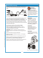
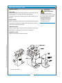
The water line must terminate in a 3/8” MNTP quick-disconnect
fitting, which will connect to the provided flex line. See Figure 2
below.
SHOCK HAZARD
Brewer must be properly
grounded to prevent possible
shock hazard. DO NOT assume
a plumbing line will provide
such a ground. Electrical shock
will cause death or serious
injury.
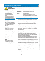
Fig. 2 Water Supply Installation
In some areas, local codes require a backflow preventer (check
valve) to be installed on the inlet water line. If a backflow
preventer is used, you must install a water hammer arrester in the
incoming line, between the backflow preventer and the brewer
inlet, as far away from the brewer as space will allow. This will
relieve the excessive back pressures that can cause faucet leaks
and solenoid malfunctions.
ELECTRICIAN’S INSTALLATION INSTRUCTIONS
REFER TO ELECTRICAL SPECIFICATIONS - Page 1
Check the nameplate to determine correct electrical service
required for the Brewer to be installed.
913 p/n 2M-75937 Owners Manual 8718, 8738 Coffee Brewer
WARNING:
IMPORTANT: Before connecting to electricity, make sure
automatic brewers are connected to the water supply and tank
is filled.
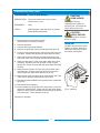
Remove front panel to access terminal block.
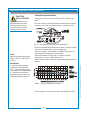
Model 8717 requires a 120/240 volt 3-wire (L1, L2, Neut) plus
Gnd 30 amp circuit.
IMPORTANT:
Supply power must match
nameplate for voltage and
phase. Connecting to the
wrong voltage will damage the
brewer or result in decreased
performance. Such damage is
not covered by warranty.
IMPORTANT:
Do not connect brewer to
electrical power until you are
ready to fill the tank. See
instructions on page 6.
IMPORTANT:
The ground lug of the brewer
must be connected to a suitable
building ground.
Model 8737 requires a 2-wire (L1, L2) plus Gnd 30 amp circuit.
Flexible conduit is recommended for electrical connection to
allow brewer to be moved for cleaning underneath.
Flexible or rigid conduit must be connected to the brewer with a
suitable strain relief (provided by electrical contractor).
Fig. 3 120/240 Volt Terminal Block
5