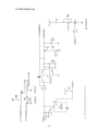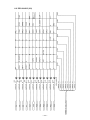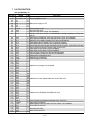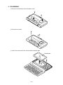
1
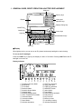
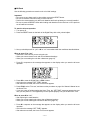
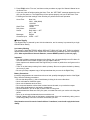
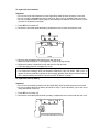
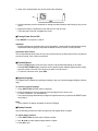
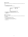
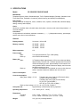
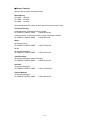
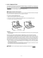
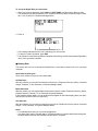
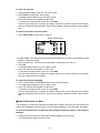
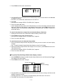
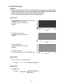
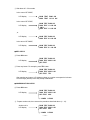
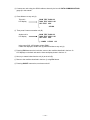
(without price)
SF-5580E/5780E/5980E (ZX-877)
JAN. 1997
R
CONTENTS
1. GENERAL GUIDE, RESET ORERATION & BATTERY REPLACEMENT -------- 1
2. SPECIFICATIONS -------------------------------------------------------------------------------- 7
3. DATA COMMUNICATIONS -------------------------------------------------------------------- 9
4. ERROR MESSAGES --------------------------------------------------------------------------- 13
5. OPERATION CHECK -------------------------------------------------------------------------- 14
6. SCHEMATIC DIAGRAMS
6-1. Z876-1 ASS’Y*5 ~ *7 (1/4) -------------------------------------------------------------- 17
Z876-1 ASS’Y*5 ~ *7 (2/4) -------------------------------------------------------------- 18
Z876-1 ASS’Y*5 ~ *7 (3/4) -------------------------------------------------------------- 19
Z876-1 ASS’Y*5 ~ *7 (4/4) -------------------------------------------------------------- 20
6-2. Z876-2 ASS’Y (1/2) ----------------------------------------------------------------------- 21
Z876-2 ASS’Y (2/2) ----------------------------------------------------------------------- 22
7. LSI PIN FUNCTION ----------------------------------------------------------------------------- 23
8. DISASSEMBLY ---------------------------------------------------------------------------------- 24
9. PARTS LIST -------------------------------------------------------------------------------------- 27
10. EXPLODED VIEW ------------------------------------------------------------------------------ 30
1. GENERAL GUIDE, RESET OPERATION & BATTERY REPLACEMENT
Mode key
Memory keys
Display
10-key pad
Operator keys
Display Change key
ON/OFF key
Mode keys
Cursor keys
Light key
Scroll/Search keys
Function key
ESC key
Alpha keyboard
■ Display
When lighting is dim, you can turn on an EL (electro-luminescent) backlight for easier viewing.
To turn on the EL backlight
Press the LIGHT key to light up the display for about 15 seconds. Pressing LIGHT while the EL
backlight is on turns it off.
Display Indicators
~
B
N
1
1
2
3
4
5
6
7
8
9
0
A
B
2
3
4
5
6
Telephone Directory Mode
Memo Mode
To Do Mode
Reminder Mode
Schedule Keeper Mode
Calendar Mode
Expense Manager Mode
Home Time/World Time Mode
Calculator Mode
Conversion Modes
Game Modes
Indicates data above
—1—
7
C
D
E
F
G
H
I
J
K
L
M
N
8
9 0
A
SHIFT key operation
Upper-case input
CODE key operation
NEW/EDIT screen
Index display
Data display
Snooze feature activated
Daily alarm on
Key sound on
Memory locked
Low battery warning
Indicates data below
■ All-Reset
Use the following procedure to reset the unit to its initial settings.
Important!
• Do not use a very sharp pencil or other object to press the RESET button.
• Be sure to reset the unit before using it for the first time.
• Perform the reset operation only after main batteries and back-up battery are correctly installed.
• Be sure to press the RESET button after loading main batteries for the first time or if the previous
set of batteries went dead.
To start the all-reset operation
1. Turn power off.
2. Press the RESET button on the back of the Digital Diary with a thin, pointed object.
3. Now you should press Y for “yes” or N for “no” in accordance with the conditions described below.
When to press Y for “yes”
• When this is the first time you are using the unit.
• When you want to reset the unit and clear all data and settings.
• When you are resetting the unit after a data error (page 13).
1. Press Y in response to the message that appears on the display when you start the all-reset
operation.
2. Press OK to reset the Digital Diary or ESC to abort.
• At this time the message “SET TIME!” appears.
• After about two seconds, the Home Time screen appears.
3. Press FUNC, select “Time set”, and then use the procedure on page 18 of Owner’s Manual to set
the Home Time.
• If you turn power off without setting the Home Time, the “SET TIME!” message appears the next
time you turn power on. The Digital Diary will not operate properly until you set the Home Time.
When to press N for “no”
• After replacing the main batteries.
• When you are not resetting the unit to clear all data and settings.
• When you are not resetting the unit after a data error (page 13).
1. Press N in response to the message that appears on the display when you start the all-reset
operation.
• At this time the message “SET TIME!” appears.
• After about two seconds, the Home Time screen appears.
—2—
2. Press FUNC, select “Time set”, and then use the procedure on page 18 of Owner’s Manual to set
the Home Time.
• If you turn power off without setting the Home Time, the “SET TIME!” message appears the next
time you turn power on. The Digital Diary will not operate properly until you set the Home Time.
• Following are the initial settings of the unit after you perform the all-reset operation.
Home Time:
World Time:
Daily Alarm:
Sound:
Messages:
Character input:
New York
JAN 1, 1996 (MON)
12:00 AM
12-hour format
London
12:00 AM
Daily alarm — OFF
Key — ON
English
CAPS — OFF
■ Power Supply
Your Digital Diary is powered by two AAA-size batteries, and its memory is protected by a single
CR2032 lithium battery.
Low battery Warning
The message, “MAIN BATTERIES WEAK! REPLACE THEM! UNIT WILL NOT TURN ON AGAIN!”
appears when battery power is low. Replace the main batteries immediately after this message appears. After replacement of the main batteries, execute RESEToperation. (refer to 4 page)
Important!
• After the low battery message appears on the display, the unit automatically turns off in about 10
seconds and will not turn back on again until you replace batteries.
• Never replace main batteries while the Digital Diary is turned on (while there are figures on the
display).
• There is not low battery warning for the back-up battery. Be sure to replace the back-up battery
once every 5 years.
• Be sure you keep a separate copy of all important data that you store in the Digital Diary.
Battery Precautions
Incorrectly using batteries can cause them to burst or leak, possibly damaging the interior of the Digital
Diary. Note the following precautions.
•
•
•
•
•
•
•
Be sure that the positive (+) side of each battery is facing in the correct directions.
Never mix batteries of different types.
Never mix old batteries and new ones.
Do not expose batteries to direct heat, let them become shorted, or try to take them apart.
Never leave dead batteries in the battery compartment.
Remove batteries if you do not play to use the unit for a long time.
Replace batteries at least once every five years, no matter how much you use the unit during that
period.
• Never try to recharge the batteries that come with the unit.
• Should a battery leak, clean out the battery compartment of the unit immediately, taking care to
avoid letting battery fluid come into direct contact with your skin.
Keep batteries out of the reach of small children. If swallowed, consult with a physician immediately.
—3—
To replace the main batteries
Important!
• Do not remove the main batteries from the Digital Diary while the back-up battery is removed.
• Be sure to replace both batteries with two new ones. Do not mix an old battery with a new one.
• Be sure to press the RESET button (page 2) after loading main batteries for the first time or if the
previous set of batteries went dead.
1. Press OFF to turn power off.
2. Remove the screw that holds the battery compartment cover in place and open the cover.
RESET
3. Remove both old batteries and replace them with new ones.
• Make sure that the positive (+) and negative (–) ends are facing correctly.
4. Replace the battery compartment cover and secure it with its screw.
• Take care that you do not overtighten the screw.
5. Press the RESET button.
• This causes the message “ARE YOU USING A NEW UNIT FOR THE FIRST TIME (Y/N)?” to
appear. Be sure to press N in response to this message (pressing Y will delete all data in memory).
Next, continue with the procedures in the section title “All-Reset” on page 2.
To replace the back-up battery
Important!
• Do not remove the back-up battery from the Digital Diary while the main batteries are removed.
• Be sure to replace the back-up battery at least once every 5 years. Otherwise, you run the risk of
losing data stored in memory.
1. Press OFF to turn power off.
2. Remove the screw that holds the back-up battery compartment cover in place and open the cover.
RESET
—4—
3. Insert a thin, pointed object into (A) and remove the old battery.
(A)
4. Load a new battery into the compartment, making sure that its positive side is facing up (so you can
see it).
5. Replace the battery compartment cover and secure it with its screw.
• Take care that you do not overtighten the screw.
■ Turning Power On and Off
Press ON/OFF to turn power on and off.
Important!
• If nothing appears on the display when you turn on power, it means that the main batteries are low.
Replace the batteries (page 4) and press the RESET button to resume normal operation.
Auto Power Off Function
The unit automatically turns power off if you do not press any key for about three minutes. Any alarms
you set still sound, even if power is turned off.
■ Function Menus
•
•
•
•
Pressing FUNC displays a function menu, whose contents differs depending on the mode.
Pressing SHIFT FUNC displays a function menu of general system settings (system function menu).
Input the number of the left of the function you want to use to select it.
To exit from a function menu, press ESC.
■ System Language
Your Digital Diary is capable of producing messages in any one of three languages (English, German,
Italy).
To select the system language
1. Press SHIFT FUNC and then select “Language”.
2. Press the number key that corresponds to the language that you want to use.
• To select “ENGLISH”, you would press 1.
• The system language automatically changes to English whenever you perform the RESET operation (page 2).
Note
• In this manual, all display messages are shown in English.
■ Display Contrast
Use the following procedure to make the figures on the display darker or lighter.
To adjust display contrast
1. Press SHIFT FUNC and then select “Display contrast”.
2. Use O and P to make display images darker or lighter.
3. Press OK to quit.
—5—
■ Key Input Sound
When the key input sound is turned on, your Digital Diary emits a beep each time you press one of its
keys.
To turn key input sound on and off
1. Press SHIFT FUNC and then select “Key tone.”
Currently selected setting
2. Use O and P to turn the key input sound on and off.
• The
indicator is on the display while the key input sound is on.
3. Press OK to quit.
■ Destructive Backspace
When destructive backspace is turned on, the character at the cursor position is deleted when you
press the BS key.
To turn destructive backspace on and off
1. Press SHIFT FUNC and then select “Backspace”.
2. Use O and P to turn destructive backspace on and off.
3. Press OK to quit.
—6—
2. SPECIFICATIONS
Model:
SF-5580E/SF-5780E/SF-5980E
Main Modes:
Telephone Directory, Memo, Schedule Keeper, To Do, Expense Manager, Reminder, Calendar, Home
Time, World Time, Calculator, Conversion (metric/currency) and Game (Poker/Blackjack)
Data storage:
Storage and recall of telephone, memo, schedule, to do, expense, reminder data; calendar display;
editing; memory status display
Clock:
World time; reminder alarm; schedule alarm; daily alarm; accuracy under normal temperatures: ±3
seconds average
Calculation:
12-digit arithmetic calculations; arithmetic constants (+, –, ×, ÷); independent memory; percentages;
square roots; other mixed calculations
General:
Display element:
26-column × 8-line LCD
Memory capacity:
SF-5580E: 128 KB
SF-5780E: 256 KB
SF-5980E: 512 KB
Main component:
LSI
Power supply:
Main:
Back-up:
Two AAA-size batteries (Type: LR03 (AM4))
One CR2032 lithium battery
Battery life:
Main:
Back-up:
Power consumption:
In Telephone Mode, approximately 100 hours continuous display;
approximately 70 hours with 5 minutes operation and 55 minutes
continuous display per hour; approximately 60 hours with 5 minutes operation and 52 minutes continuous display, and 3 minutes
backlight operation per hour
5 years if main batteries are replaced as soon as they become
weak. 6 months if dead main batteries are left in the unit.
0.25 W
Current consumption:
Main (Input voltage = 3.0 V):
Telephone top menu (Light from EL doesn't shine)3.9 mA (TYP.)/4.8 mA (MAX.)
Telephone top menu (Light from EL shines)27 mA (TYP.)/38 mA (MAX.)
OFF- 90 µA (TYP.)/120 µA (MAX.)
Back-up (Input voltage = 3.0 V): 18 µA (TYP.)/40 µA (MAX.)
Auto power off:
Approximately 3 minutes after last key operation
Operating temperature:
0 °C ~ 40 °C (30 °F ~ 104 °F)
Dimensions:
Unfolded:
Folded:
8.8H × 163W × 169D mm (3/8"H × 67/16"W × 65/8"D)
21.5H × 163W × 91.5D mm (7/8"H × 67/16"W × 35/8"D)
Weight:
251 g (8.9 oz) including batteries
—7—
■ Memory Capacity
Memory capacity differs according to model.
Model Memory
SF-5580E: 128 Kbyte
SF-5780E: 256 Kbyte
SF-5980E: 512 Kbyte
The following shows the number of items that can be stored in each model.
Telephone Directory
8-character name, 10-character Phone 1 number
SF-5580E/SF-5780E/SF-5980E:
4,000/9,000/19,000
8-character name, 10-character Phone 1 number, 20-character address
SF-5580E/SF-5780E/SF-5980E:
2,000/4,500/9,500
Memo
20-character memo
SF-5580E/SF-5780E/SF-5980E:
3,400/7,700/16,000
To Do
20-character description
SF-5580E/SF-5780E/SF-5980E:
3,200/7,200/15,200
Schedule Keeper
20-character description, alarm time setting
SF-5580E/SF-5780E/SF-5980E:
2,900/6,500/13,500
Reminder
10-character description
SF-5580E/SF-5780E/SF-5980E:
5,000/11,250/23,800
Expense Manager
10-character description
SF-5580E/SF-5780E/SF-5980E:
3,500/7,900/18,600
—8—
3. DATA COMMUNICATIONS
You can transfer data between two CASIO SF-5580E,SF-5780E, or SF-5980E units, or between your
Digital Diary and a personal computer only. You cannot exchange data with any other CASIO Digital
Diary model. Data communications can be performed while in the Telephone Directory, Memo, Schedule
Keeper, Calender, To Do, Reminder, or Expense Manager Mode.
■ Setting Up for Data Communications
The following describes what you would do to set up for data communications between two Digital
Diary units or between a Digital Diary unit and a personal computer.
To connect to another Digital Diary unit
1. Make sure that the power of both units is turned off.
2. Remove the covers from the data communications jacks on the two Digital Diary units.
3. Connect the two units using the SB-62 cable.
SB-62 cable
Important!
• Be sure to replace the connector covers on the Digital Diary units when you are not perfoming data
communications.
Performing data communications between a Digital Diary unit and a personal computer
You must purchase an optional CASIO Data Communication Package in order to perform data communication between your Digital Diary unit and a personal computer. Please note that there are a
number of different CASIO Data Communication packages to suit various computers and Digital Diary
types. Because of this, you should note the following important points when purchasing a Data Communication Package. If you have any question about which package you need, consult with a expert.
• Make sure the Data Communication Package (FA-127) is designed for you with your particular
model of personal computer.
• For information on how to connect the Digital Diary to a personal computer, see the user’s manual
that comes with the Data Communication Package (FA-127).
■ REMARK: FA-127 is the Personal Computer Link (software and cable unit) for Windows.
—9—
To set up the Digital Diary to receive data
1. While any screen is displayed, press FUNC (or SHIFT FUNC) and then select “Receive data”.
• You can perform the above operation in the Telephone Directory, Memo, Schedule Keeper, Calendar, To Do, Reminder, or Expense Manager Mode.
2. Press Y.
• This message indicates that the unit is standing by to receive data.
• To abort the receive operation, press ESC.
• This procedure is the same regardless of whether data is being received from another Digital Diary
unit or from a personal computer.
■ Sending Data
This section tells you how to operate the Digital Diary to send data to another unit or to a personal
computer.
About data transfer types…
There are a number of ways you can transfer data.
All Data Items
With this method, you can send all data items stored in the Telephone Directory, Memo, Schedule
Keeper, Calendar, To Do, Reminder, or Expense Manager Mode.
Mode Data Items
With this method, you can send all data items stored in specific modes (Telephone Directory, Memo,
Schedule Keeper, Calendar, To Do, Reminder, Expense Manager).
In the Schedule Keeper Mode, you can send items that appear on the index display (which you specified using the function menu’s List type item).
One Data Item
With this method, you can send one data item stored in the Telephone Directory, Memo, Schedule
Keeper, To Do, Reminder, or Expense Manager Mode.
Notes
• For Calendar Mode data, you can send highlight data.
• If an alarm (Daily Alarm, Schedule Alarm, or Reminder Alarm) is reached while data is being sent,
the alarm does not sound until the data send operation is complete.
— 10 —
To send one data item
1. Display the data display of the item you want to send.
2. Press FUNC and then select “Send record”.
• A message appears asking if you are ready to send.
3. Press Y to start the send operation, or N to abort.
• To interrupt the send operation at any time, press ESC.
• After the send operation is complete, the display returns to the screen that was on the display
before you started the send operation. Then you can repeat the above procedure to send another
item.
To send all data items in specific modes
1. Press SHIFT FUNC and then select “Send all”.
Pointer (selected file)
Marker (current setting)
2. Use M and N to move the pointer to the mode whose data items you want to send, and then use O
and P to change the setting.
• Data in modes set to “Yes” will be sent, while data in modes set to “No” will not.
3. Press OK.
• A message appears asking if you are ready to send.
4. Press Y to start the send operation, or N to abort.
• To interrupt the send operation at any time, press ESC.
• After the send operation is complete, the display returns to the screen that was on the display
before you started the send operation.
To send Calender data (highlights)
1. In the Calender Mode, press FUNC and then select “Send (Holidays)”.
• A message appears asking if you are ready to send.
2. Press Y to start the send operation, or N to abort.
• To interrupt the send operation at any time, press ESC.
• After the send operation is complete, the display returns to the screen that was on the display
before you started the send operation. Then you can repeat the above procedure to send another
item.
■ Send All Data Items In a Mode
The procedure you should use depends on whether the file whose data items you are sending has
multiple files (Telephone Directory, Memo, To DO, Expense Manager) or not (Schedule, Reminder).
To send all data items from a multiple file mode (Telephone Directory, Memo, To Do, Expense
Manager)
1. Display the initial screen of the mode that contains the data you want to send.
• You can display the initial screen for any file.
— 11 —
2. Press FUNC and then select “Send all files”.
3. Use M and N to move the pointer to the file whose data you want to send, and then use O and P
to change the setting.
• Files set to “Yes” will be sent, while those set to “No” will not.
4. Press OK.
• At this time the message “READY TO SEND (Y/N)?” appears.
5. Press Y to send or N to abort.
• In the Telephone Directory, Memo, and To Do Modes you can also use another method to send all
data items. While the index display or data display is on the screen, press FUNC and then select
“Send all records”. This causes the message “READY TO SEND (Y/N)?” to appear, so press Y to
send or N to abort.
To send all data items from a single file mode (Schedule Keeper, Reminder)
1. Display the initial screen of the mode that contains the data you want to send.
2. Press FUNC and then select “Send all records”.
• At this time the message “READY TO SEND (Y/N)?” appears.
3. Press Y to send or N to abort.
To send listed records in the Schedule Keeper Mode
1. Enter the Schedule Keeper Mode and specify the items you want to send in the index display
contents.
• See “To specify Schedule Keeper Mode index display contents” on this page.
2. While the Schedule Keeper Mode index display is on the screen, press FUNC and then select
“Send listed records”.
• At this time the message “READY TO SEND (Y/N)?” appears.
3. Press Y to send or N to abort.
■ To specify Schedule Keeper Mode index display contents
1. Press SCHEDULE to display the initial Schedule Keeper Mode screen, and then press M, N, , or
to change to the index display.
2. Press FUNC and then select “List type”.
Pointer (selected type)
Marker
(Current setting)
3. Use M and N to move the pointer next to the schedule type you want to change, and then use O
and P to change the setting.
• Schedule types set to “Yes” appear in the index display, while those set to “No” do not.
4. Press OK to quit and return to the index display.
— 12 —
4. ERROR MESSAGES
Data Error Message
The data error message appears whenever the Digital Diary’s internal check discovers a problem with
data stored in memory.
Appearance of the data error message indicates that you must perform the all-reset procedure to
correct the problem. Start out with the procedure under “To start the all-reset operation” on page 2,
and continue with the procedure under “When to press Y for “Yes” on page 2”.
Important!
• Even though you are not using the unit for the first time, you must press Y (for “Yes”) when the unit
asks “ARE YOU USING A NEW UNIT FOR THE FIRST TIME (Y/N)?” in order to reset the unit
after a data error occurs.
If you still have trouble after trying the RESET operation, you may have a hardware problem. If so,
consult with your nearest CASIO dealer.
■ Message Table
Message
Meaning
Action
NOT FOUND!
PRESS ESC TO QUIT.
Data specified in search operation
does not exist in memory.
Change specification or cancel
search.
MEMORY FULL,
PRESS ANY KEY.
No more room in memory for storage of data.
Delete unnecessary data items
from memory.
ALARM TIME COINCIDENT!
Attempt to set an alarm that is already used for another entry.
Set a different alarm time or
change the existing alarm time.
ALARM TIME ALREADY
PASSED!
Attempt to set an alarm for a time
or data that is already passed.
Set a different alarm time.
DATA COMM. ERROR,
PRESS ANY KEY!
Error during data communications.
Cancel the operation and try
again.
ARE YOU USING A NEW
UNIT FOR THE FIRST TIME
(Y/N)?
The reset procedure has started.
See page 2.
CLEAR MEMORY AND SET
UP UNIT FOR OPERATION?
YES (OK)/NO (ESC)
The reset procedure is in
progress.
See page 2.
DATA ERROR! CHECK
YOUR OWNER’S MANUAL
FOR PROCEDURE!
Data corrupted by strong impact,
electrostatic charge, etc..
See this page.
MAIN BATTERIES WEAK!
REPLACE THEM! UNIT WILL
NOT TURN ON AGAIN!
The main batteries are getting
weak.
Replace main batteries immediately (page 4).
— 13 —
5. OPERATION CHECK
REMARKS:
1. Executing this check, the data stored in this Digital Diary disappear. So if you won’t disappear this important data, you should store its data in another Digital Diary (SF-5580E/5780E/
5980E) referring to the item 3. Data communications in this manual.
2. You can not put out the light from EL while executing this check.
● LCD CHECK
1 Press RESET button on the rear panel while pressing OK button on the front panel.
LCD display appears as shown right.
(figure-1)
figure-1
2 Press OK button four times.
LCD display appears as shown right.
(figure-2)
figure-2
3 Then press OK button.
LCD display appears as shown right.
(figure-3)
4 Press OK button again.
LCD display appears as shown in the figure-1 again.
figure-3
● ROM CHECK
5 Wait 4 ~ 5 seconds, then press OK button.
LCD display
ROM TEST ROM OK
● RAM CHECK
6 Press OK button.
LCD display
ROM TEST ROM OK
RAM TEST
— 14 —
7 Wait about 45 ~ 50 seconds.
In the case of SF-5580E,
LCD display
ROM TEST ROM OK
RAM TEST 1 2 8 K OK
In the case of SF-5780E,
LCD display
ROM TEST ROM OK
RAM TEST 1 2 8 K OK
2N D
RAM TEST 1 2 8 K OK
, or
LCD display
ROM TEST ROM OK
RAM TEST 2 5 6 K OK
In the case of SF-5980E,
LCD display
ROM TEST ROM OK
RAM TEST 5 1 2 K OK
● KEY CHECK
8 Press OK button.
LCD display
ROM TEST ROM OK
RAM TEST XXX K OK
KEY TEST
9 Press any button. For example, press TEL button.
LCD display
ROM TEST ROM OK
RAM TEST XXX K OK
KEY TEST TEL
After pressing any button, LCD displays a letter or a number correspond to its button.
Check all keys (buttons) in this way except to OK button.
● COMMUNICATION CHECK
0 Press OK button.
LCD display
ROM TEST ROM OK
RAM TEST XXX K OK
KEY TEST XXX
1 COMM
2 ECHO
A Prepare another unit, then execute the procedure described above (1 ~ 10).
Another unit’s
LCD display
ROM TEST ROM OK
RAM TEST XXX K OK
KEY TEST XXX
1 COMM
— 15 —
2 ECHO
B Connect two units using the SB-62 cable as shown by the item 3. DATA COMMUNICATIONS
(page 9) in this manual.
C Press 2 button on any unit (A).
This unit’s
LCD display
ROM TEST ROM OK
RAM TEST XXX K OK
KEY TEST XXX
2 ECHO
D Then press 1 button on another unit (B).
Another unit’s
LCD display
ROM TEST ROM OK
RAM TEST XXX K OK
KEY TEST XXX
1 COMM
2 ECHO
OK
In the case of NG, LCD displays a letter “FAIL”.
If “OK” was displayed, another unit (B) transmitted data to any unit (A).
E Pressing ESC buttons on the both units, return to the condition described in the item 12 .
LCD displays on the both units are the same as display shown in the item 11 .
F Next, try to transmit data from the unit (A) to the unit (B).
G Return to the condition described in the item B using ESC button.
H Pressing ON/OFF button twice, turn these units off.
— 16 —
6. SCHEMATIC DIAGRAMS
6-1. Z876-1 ASS’Y*5 ~ *7 (1/4)
— 17 —
6-1. Z876-1 ASS’Y*5 ~ *7 (2/4)
— 18 —
6-1. Z876-1 ASS’Y*5 ~ *7 (3/4)
— 19 —
6-1. Z876-1 ASS’Y*5 ~ *7 (4/4)
— 20 —
6-2. Z876-2 ASS’Y (1/2)
— 21 —
6-2. Z876-2 ASS’Y (2/2)
— 22 —
7. LSI PIN FUNCTION
CPU (LC868016A): U1
Pin No.
Name
I/O
Function
1
VDD
I Power supply for this CPU
2~65
S1~48,C1~16 O Common signals to LCD
66
V1
O
67
V2
O
68
V3
O Bias power supply to LCD
69
V4
O
70
V5
O
71
VLCD
O Power supply to LCD
78
VSS
— Ground for this CPU
80
P41
O Clock for LCD driver LSI(U2, U3:LC868900)
82
P43
O Signal to LCD driver LSI(U2, U3:LC868900)(AC voltage is supplied to LCD by this
signal.)
84
P46
O Read signal to RAM(U42, U62) and LCD driver LSI(U2, U3:LC868900)
85
P47
O Write signal to RAM(U42, U62) and LCD driver LSI(U2, U3:LC868900)
87
P71
I Detection of low battery voltage(=2.5V) from IC(U2:S80725)
90
P10
O Serial data output to another unit or a personal computer
91
P11
I Serial data input from another unit or a personal computer
93
P13
O Control signal to power supply IC(DC/AC inverter IC) for EL (H: EL-OFF/L: EL-ON)
96
P16
O Control signal for buzzer(H: buzzer-ON/L: buzzer-OFF)
98
P57
O Chip select to LCD driver LSI(U3:LC868900)
99
P56
O Chip select to LCD driver LSI(U2:LC868900)
101
P54
O Clock to IC(U8:74HC273) for the keyboard data latch
102
P53
O Control signal to LCD driver LSI(U2, U3:LC868900)
104
P51
O Address bus to RAM(U42, U62)
105
P50
O Address bus to ROM(U5)
106
VDD1
O Power supply for this CPU
107
P30
I
108
P31
I
109
P32
I
110
P33
I Signals for key assign from keyboard
111
P34
I
112
P35
I
113
P36
I
114
P37
I
115
P00
I/O
116
P01
I/O
117
P02
I/O
118
P03
I/O Address bus to the address data latch IC(U7:74HC373)
119
P04
I/O
120
P05
I/O
121
P06
I/O
122
P07
I/O
123
P20
O
124
P21
O
125
P22
O
126
P23
O Address bus to ROM(U5) and RAM(U42, U62)
127
P24
O
128
P25
O
129
P26
O
130
P27
O
131
ADLC
O Control signal to the address data latch IC(U7:74HC373)
132
-EROE
O Chip select to ROM(U5)
133
-RST
I Reset signal for this CPU and LCD driver LSI(U2, U3:LC868900)
134
XT1
I Timer clock for this CPU
135
XT2
O
136
VSS
— Ground for this CPU
137
CF1
I Main clock for this CPU
138
CF2
O
— 23 —
8. DISASSEMBLY
1 Remove two screws then remove the battery cover.
2 Remove three screws.
3 Open the unit and remove two screws behind the display plate.
Display plate
— 24 —
4 Remove Lower cabinet (keyboard).
Lower cabinet
(keyboard)
5 Remove Rubber key and knob.
Rubber key
6 Desolder the wire connected
to the buzzer on the Lower
cabinet (keyboard) from keyboard PCB ass’y.
Knob
7 Remove Lower cabinet (display).
Lower cabinet
(display)
— 25 —
8 Remove screws on PCB shown above then remove PCB ass’y.
Main PCB
(11 screws)
Keyboard PCB
(13 screws)
9 Separate upper cabinets.
REMARK:
Heat seal and wires must be placed inside of the hinge in order for the Lower cabinet (keyboard) to fit
into place.
If heat seal and wires are placed improperly, they are damaged.
Heat seal
Wires (Black/Red)
Hinge
Lower cabinet
— 26 —
9. PARTS LIST
N
Item
Code No.
Parts Name
Specification
Applicable
Q R
Z876-1 ASS'Y
* There are two type of Z876-1 ASS'Ys in SF-5780E--A type & B type.
N
U7
U8
U62
* U42, U62
* U62
U42, U62
XT1
XT2
Q30
D2~D17
L3
2114 5771
2114 5770
2012 5520
2012 5520
2012 5519
2012 5519
2590 2691
2590 2690
2259 2712
2390 3005
6420 1950
TTL-IC
TTL-IC
LSI
LSI
LSI
LSI
Oscillator
Crystal oscillator
Transistor
Diode
Coil
CMO-09-HC373
CMO-09-HC273
CMO-02-128NC-01
CMO-02-128NC-01
CMO-02-256SN-01
CMO-02-256SN-01
RER-01-12
QUA-02-26
TRR-01-M6
DIO-01-LS4148
C01-02-4615
Common
Common
SF-5580E
SF-5780E, A-type
SF-5780E, B-type
SF-5980E
Common
Common
Common
Common
Common
1
1
1
2
1
2
1
1
1
16
1
B
B
B
B
B
B
B
B
C
C
C
The following electronic parts will be not supplied from CASIO.
R7
R15~16
R24
R30
R31
C1~2
C3~4
C7~14, C16~21,
C31, C34
C15
C30
C32
C33
U2
U3
Q2, Q10
D1
D20
L2
L4
1
2
3
Chip resister(1.5KW)
Chip resister(1MW)
Chip resister(100KW)
Chip resister(220W)
Chip resister(10KW)
Chip capacitor(33pF)
Chip capacitor(18pF)
Chip capacitor(0.1mF)
RES-01-1.5K
RES-01-1M
RES-01-100K
RES-01-220
RES-01-10K
CAP-01-33
CAP-01-18
CAP-01-01
Common
Common
Common
Common
Common
Common
Common
Common
1
2
1
1
1
2
2
16
Electrolytic capacitor(10mF)
Chip capacitor(15nF)
Chip capacitor(68pF)
Chip capacitor(1mF)
CAP-02-10-25
CAP-01-0015
CAP-01-68
CAP-02-1-50
Common
Common
Common
Common
1
1
1
1
CMO-14-80715
CMO-10-R1501B
TRR-01-NPNL6
DIO-01-LS4148
DIO-03-BAT43
COI-02-4630
IND-01-120
JCK-01-1169
BAC-01-988+
BAC-01-988-
Common
Common
Common
Common
Common
Common
Common
Common
Common
Common
1
1
2
1
1
1
1
1
1
1
Z876-2 ASS'Y
2114 5768 IC
3065 0708 IC
2259 2713 Transistor
2390 3005 Diode
2390 3004 Schottky diode
6419 6430 Coil
3122 3509 Inductor
3502 2225 Mini jack
6419 6460 Battery plate +
6419 6470 Battery plate -
The following electronic parts will be not supplied from CASIO.
Chip resister(100KW)
R1
Chip resister(1kW)
R8
Chip resister(10KW)
R9
Chip resister(1MW)
R17
Chip resister(100W)
R18, R60
Notes: N – New parts
Q – Quantity used per unit
R – Rank
RES-01-100K
RES-01-1K
RES-01-10K
RES-01-1M
RES-01-100
R–A:
B:
C:
X:
— 27 —
Common
1
Common
1
Common
1
Common
1
Common
2
Essential
Stock recommended
Others
No stock recommended
C
C
C
C
C
C
C
C
C
C
N
Item
R25
R28
C5
C6~7, C35
C24
C36
N
N
N
N
N
N
4
4
4
5
6
7
8
9
10
11
12
12
12
13
13
13
14
15
15
15
16
16
16
17
18
18
18
19
20
21
22
23
24
24
24
25
26
26
26
27
27
27
Notes:
Code No.
Parts Name
Specification
Chip resister(1.8kW)
Chip resister(47KW)
Chip capacitor(0.1mF)
Electrolytic capacitor(100mF)
Chip capacitor(4700pF)
Tantalum capacitor(10mF)
PCB ASSEMBLY
6420 1880 Z876-1 ass'y
6420 1890 Z876-1 ass'y
6420 1900 Z876-1 ass'y
6419 7320 Z876-2 ass'y
5610 9420 Heat seal
5610 9430 Heat seal
5610 9440 Heat seal
3502 2224 Heat seal
3335 6535 LCD
3312 0057 EL
COMPONENTS
6419 6180 Rubber key
6419 6190 Rubber key
6419 6200 Rubber key
6419 6210 Upper cabinet(display)
6419 6220 Upper cabinet(display)
6419 6230 Upper cabinet(display)
6419 6240 Pad
6419 6250 Lower cabinet(keyboard)
6419 6270 Lower cabinet(keyboard)
6419 6290 Lower cabinet(keyboard)
6419 6310 Upper cabinet(keyboard)
6419 6320 Upper cabinet(keyboard)
6419 6330 Upper cabinet(keyboard)
6419 6340 Hinge rubber
6419 6350 Rubber key
6419 6360 Rubber key
6419 6370 Rubber key
6419 6400 Steel nut
6419 6050 Battery spring
6419 6060 Battery spring
6419 6100 Battery spring
6419 6080 Rubber key
6419 6120 Knob
6419 6130 Knob
6419 6140 Knob
3122 3508 Buzzer
3851 2068 Display plate
3851 2069 Display plate
3851 2070 Display plate
6419 5720 Lower cabinet(display)
6419 5730 Lower cabinet(display)
6419 5740 Lower cabinet(display)
N – New parts
Q – Quantity used per unit
R – Rank
— 28 —
Applicable
Q R
RES-01-1.8K
RES-01-47K
CAP-01-01
CAP-02-100-25
CAP-01-4700
CAP-04-10-6.3
Common
Common
Common
Common
Common
Common
1
1
1
3
1
1
C341328A*5
C341328A*6
C341328A*7
C341329*1
HES-03-ZX876A
HES-03-ZX876B
HES-01-161055
HES-01-064065
LCD-03-ZX876
LAM-03-ZX876
SF-5580E
SF-5780E
SF-5980E
Common
Common
Common
Common
Common
Common
Common
1
1
1
1
1
1
1
1
1
1
B
B
B
B
B
B
B
B
B
B
SF-5580E
1
SF-5780E
1
SF-5980E
1
SF-5580E
1
SF-5780E
1
SF-5980E
1
Common
2
SF-5580E
1
SF-5780E
1
SF-5980E
1
SF-5580E
1
SF-5780E
1
SF-5980E
1
Common
1
SF-5580E
1
SF-5780E
1
SF-5980E
1
Common
2
Common
1
Common
1
Common
1
Common
1
SF-5580E
1
SF-5780E
1
SF-5980E
1
Common
1
SF-5580E
1
SF-5780E
1
SF-5980E
1
SF-5580E
1
SF-5780E
1
SF-5980E
1
Essential
Stock recommended
Others
No stock recommended
C
C
C
C
C
C
X
C
C
C
C
C
C
X
C
C
C
X
X
X
X
C
C
C
C
X
B
B
B
C
C
C
KEY-04-ZX876A-1
KEY-04-ZX876A-2
KEY-04-ZX876A-3
HOU-04-ZX876-00
HOU-04-ZX876-01
HOU-04-ZX876-02
CON-05-507327
HOU-02-ZX876-00
HOU-02-ZX876-02
HOU-02-ZX876-04
HOU-01-ZX876-00
HOU-01-ZX876-01
HOU-01-ZX876-02
HIN-01-ZX-876
KEY-04-ZX876B-1
KEY-04-ZX876B-2
KEY-04-ZX876B-3
NUT-02-M1.7
BAC-01-ZX876BAC-01-ZX876+/BAC-01-ZX876+
KEY-03-U100
LOC-01-ZX876-00
LOC-01-ZX876-01
LOC-01-ZX876-02
BUZ-02-27
LEN-01-ZX877-00
LEN-01-ZX877-01
LEN-01-ZX877-02
HOU-03-ZX876-00
HOU-03-ZX876-01
HOU-03-ZX876-02
R–A:
B:
C:
X:
N
Item
Code No.
N
N
N
28
28
28
29
30
31
32
32
32
33
33
33
6420 1920
6420 1930
6420 1940
6419 5820
6419 5830
6419 5850
6419 5890
6419 5900
6419 5910
6419 5920
6419 5930
6419 5940
Notes:
Parts Name
Plate
Plate
Plate
Screw
Screw
Jack cover
Battery cover
Battery cover
Battery cover
Battery cover
Battery cover
Battery cover
N – New parts
Q – Quantity used per unit
R – Rank
Specification
Applicable
INL-01-ZX877-00
INL-01-ZX877-01
INL-01-ZX877-02
SCR-01-1740PMTB
SCR-01-1735PBBK
JCK-02-ZX876
BAD-02-ZX876-00
BAD-02-ZX876-01
BAD-02-ZX876-02
BAD-01-ZX876-00
BAD-01-ZX876-01
BAD-01-ZX876-02
SF-5580E
SF-5780E
SF-5980E
Common
Common
Common
SF-5580E
SF-5780E
SF-5980E
SF-5580E
SF-5780E
SF-5980E
R–A:
B:
C:
X:
— 29 —
Q R
1
1
1
1
1
1
1
1
1
1
1
1
Essential
Stock recommended
Others
No stock recommended
C
C
C
C
C
C
C
C
C
C
C
C
10. EXPLODED VIEW
26
16
17
24
13
18
12
14
31
22
21
1
20
8
9
10
5
— 30 —
11
7
25
23
2
4
3
19
6
15
27
19
33
32
29
28
30
MA0200171A