1
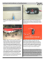
Co-Pilot II™ Infrared Flight Stabilization System Supplemental User Guide for Hard Deck (HD100) Note: Read this user guide carefully before using Hard Deck™. Distributed in the U.S. by FMA Direct 3520 Surgarloaf Parkway, Suite F-03-121 Urbana, MD 21704 Sales: (301) 798-2770 z Technical: (301) 829-5533 www.revolectrix.com Introduction Thank you for purchasing the REVOLECTRIX Hard Deck Module for Co-Pilot II. Hard Deck Module is an accessory to the Co-Pilot II Flight Stabilization System. It incorporates a barometric pressure sensor to determine the altitude of a fixed-wing model aircraft or model helicopter at any given moment. Used in tandem with the supplied static pressure tube (for fixed-wing) or static streamer (for helicopter), the Hard Deck Module can accurately detect the altitude of a model aircraft in any orientation or flight angle. With a user-selectable altitude setting of between 50 and 255 feet, Hard Deck acts like an automatic panic button, enabling Co-Pilot II stabilization at a user-defined altitude. The Hard Deck Module physically connects to the ACCY port of the Co-Pilot II Avionics Computer and draws a small amount of power from the Computer Module’s power buss. During Quick Setup of Co-Pilot II, turn on the Accesory device “Hard Deck Alt.” when prompted. When Hard Deck is detected by the CP II Avionics Computer, the setup screens offer a new 3D Flight Mode called “Level in H.Deck” which is then assigned to a particular position on a remote AUX control on the pilot’s transmitter. Once enabled, Hard Deck Flight Mode creates an invisible, safe flying boundary at the chosen altitude. Fly above the Hard Deck with stabilization completely disabled (default setting, user-adjustable). Practice new maneuvers with confidence knowing that if you become disoriented, Hard Deck will restore your model to level flight in the blink of an eye by automatically enabling CPII Flight Stabilization (with Emergency Recovery) any time the model reaches the Hard Deck altitude. CPII and other Flight Stabilization systems have had “panic button” capability for some time now. But Hard Deck Module is the first device ever offered to enable Level Flight Stabilization based on a pre-defined altitude, without the pilot having to fumble for a switch as he watches his model tumble towards earth out of control. ground temperature difference is > 15 deg F, the hard deck will be enabled whenever the Hard Deck Flight Mode is enabled. The super-bright green LED will remain lit. Conversely, if system errors are detected or the sky-to-ground temperature is < 15 deg F, CPII signals that the hard deck is disabled in the preflight screen and by angle-limiting to 45 degrees in all directions to prevent inverted flight. Angle limiting will also occur above the hard deck to signal a problem and prevent rapid loss of altitude from 3D flying or deep dives. Angle limiting only applies to a helicopter setup. Additionally, the super-bright green LED will turn OFF. User Guide Contents This manual provides complete instructions for installing, setting up and using the Hard Deck Module with an existing (or newlypurchased) Co-Pilot II Flight Stabilization System. The manual contains these sections: • • • • • • • • • • • • • • • Introduction User Guide Contents Package Contents Other Items you may Need Safety Precautions Theory of Operation Getting Ready for the Installation Specifications Prerequisites Recommended Sequence of Events Computer Software and Firmware Updates Installing the Hard Deck Module in a Fixed Wing Airplane Installing the Hard Deck Module in a Helicopter Flying with Hard Deck Module Revolectrix Limited Warranty HELICOPTERS UNDER THE DECK - When flying heli’s below the Hard Deck altitude, pitch and roll angles are limited to about 40 degrees. This new, super-stabilization, makes it impossible to invert the heli below HD altitude, lets the pilot know HD is operational, and prevents the pilot from overcontrolling the model just after a HD recovery has occurred. Additionally, the Stick Priority function is disabled below HD altitude. FIXED-WING UNDER THE DECK - Fixed-wings do not angle limit under HD altitude; however, Level stabilization is turned ON. Emergency Recovery will initiate if the model is inverted while in the deck. ABOVE THE DECK - Stabilization can be reduced or turned completely OFF (the default setting) in User Preferences. HARD DECK DISABLED - As long as there are no system errors related to altitude or emergency recovery, and the sky-to© 2012 FMA, Inc. All rights reserved. Reproduction of this publication is prohibited. Co-Pilot is a trademark of FMA, Inc. U.S. Patent 6,181,989. Foreign and other patents pending. Co-Pilot II™ Supplemental User Guide for Hard Deck (HD100) –2– User Guide Version 1.13 10/15/2012 REVOLECTRIX Package Contents Check the above package contents against what you received. If any parts are missing, contact Revolectrix customer support right away. Look for the correct Customer Support method at the following web page: http://www.revolectrix.com/support_options.htm Familiarize yourself with the various components above or refer back to this page often, as we will refer to these components by name throughout this User’s Guide. Other Items you may Need Fixed-wing Airplane installations will require the brass tubing shown in the photo at left. This tubing should be available from your local hobby shop, sold as K&S Engineering Stock #1268; 3/32 O.D. x .014 (wall thickness) Helicopter installations may require the additional items shown in the photo at left to securely mount the Hard Deck Module to the tail boom of the helicopter. These items come with all CPII Systems and are also sold separately as the CPII Accy Pack at www.store.revolectrix.com and www.usastore.revolectrix.com. Accessory Pack contents: 1) 3 sensor mounts (you may already have a spare from your CPII System) 2) 3 pcs 4” wire ties 3) Double-sided tape All Aircraft type - CA Super Glue (not shown) will also be required REVOLECTRIX –3– Co-Pilot II™ Supplemental User Guide for Hard Deck (HD100) Safety Precautions General Precautions Safety precautions for Co-Pilot II and Hard Deck: Radio controlled models are not toys! Please observe these general safety precautions: Co-Pilot II Flight Stabilization Systems and Accessories are designed for flight stabilization only. They cannot navigate the aircraft. You must control the aircraft’s flight path. Flight Stabilization, even with Hard Deck Module, should never be considered a substitute for proper instruction and training to learn the fundamentals of Model Aircraft Flying. Co-Pilot II and Hard Deck are for recreational use only. Do not install Co-Pilot II Systems in aerial photographic aircraft where there is a possibility of flying over people. Make sure that the Co-Pilot II System components are installed an operated in accordance with the Co-Pilot II Quick Start and Full Reference User Guides and make sure you have read and understand any safety instructions presented in the aforementioned documents. Besides your regular pre-flight check, also check Co-Pilot II operation before each flight. Details are in “Co-Pilot II Full Reference User Guide. Never attempt Hard Deck recoveries over you head or the heads of any spectators. Always make sure you fly away from people, property, or the pits at your local flying field. Be advised, Hard Deck is a tool for assisting a pilot to learn new maneuvers at a safe altitude. During recovery, it will take control away from the pilot for up to 2 seconds in order to force the aircraft into a level flight attitude. If level flight can not be achieved within the 2 second window, it is not likely it can be achieved due to lack of power, mechanical failure, etc. Hard Deck requires that the model remain under power at all times. In the event of engine or motor failure, Hard Deck may not be able to recover the model. In the event of mechanical failure of critical components in your model, Hard Deck may not be able to recover the model. Proper Hard Deck operation is dependent on fully-functional and flight-worthy model aircraft and electronics. Always make sure you verify the super-bright green LED is lit before you attempt Hard Deck recoveries. When properly installed, the LED is visible from the ground even at long range. If you have the Remote switch set to enable Hard Deck Flight Mode, and the green LED is ever OFF while you are flying, land immediately and determine the cause. Never assume the Hard Deck will function if the green LED is not lit. Follow all instructions in this user guide to assure safe operation. If you have not assembled and operated a radio controlled model before, obtain help from an experienced modeler. You will need guidance to successfully assemble, test and operate radio controlled models. One of the best ways to obtain help is to join your local radio control club. Never fly radio controlled aircraft near people, buildings, telephone or power lines, cars, trees or other objects on the ground or in the air. Never allow a helicopter to fly within 20 feet of you or another person. If a helicopter flies toward you or another person, stop the engine/motor immediately to prevent personal injury. Keep your radio controlled models and equipment away from children. Do not allow unauthorized people of any age to operate radio controlled models without proper supervision from an experienced modeler. In some areas of the country, you cannot legally operate radio controlled models except at approved fields. Check with local authorities first. Observe frequency control. Use spread-spectrum radio technology, or if someone else is operating a radio controlled model on the same channel as your transmitter, do not turn on your transmitter—even for a short time. A non-spread spectrum transmitter has a channel number marked somewhere on its case. When a model receives signals from two transmitters on the same channel at the same time, it cannot be controlled and will crash—possibly causing personal injury or property damage. For safety, most RC flying fields have formal frequency control rules. Follow them carefully. Do not operate your radio control transmitter within 3 miles of a flying field. Even at a distance, your transmitter can cause interference. Do not operate radio controlled models and equipment in the rain, or at night. Protect all electronic equipment from exposure to rain, water, high humidity and high temperatures. FMA Direct recommends that you join the AMA. They can help you find a club in your area. Academy of Model Aeronautics 5161 East Memorial Drive Muncie, Indiana 47302 Phone: (800) 435-9262 Web: www.modelaircraft.org Co-Pilot II™ Supplemental User Guide for Hard Deck (HD100) –4– REVOLECTRIX Theory of Operation The Hard Deck Module gives Co-Pilot II the ability to read altitude quickly and accurately with an unbelievable one foot resolution. Believe it or not, the air pressure at your feet is measurably higher than the air pressure at your head. The altitude measurement from this tiny sensor allows the activation of the new Hard Deck Flight Mode on Co-Pilot II. Measuring Pressure There are two types of air pressure at a given altitude. Static Air Pressure is just like it sounds. It is the air pressure measurement when the air is still. Total Air Pressure is the Dynamic Pressure (pressure of moving air), plus the Static Pressure. For example: when riding in a car, if you put your hand out the window, you feel the Total Air Pressure exerted on your hand. Total Air Pressure can cause altitude errors of over 100 feet on a RC model. Obviously, large errors caused by reading Total Air Pressure would make a Hard Deck impossible to achieve. So, to compensate for the pressure exerted by moving air, Static Air Pressure must always be taken from sense holes perpendicular to the air stream. Notice in the illustrations below how the moving air rams into the Pitot tube and causes the pressure to rise. On the other hand, the air on the static tube rushes by without entering the holes. Static pressure is the type of pressure we require for Hard Deck. NOTE: Hard Deck requires the static air pressure measurement to be accurate. NEVER USE A PITOT TUBE. The end of the tube must be CLOSED. For a fixed-wing installation, always use the Static pressure tube provided in the Hard Deck Module Accessory pack. For helicopter installations, always use the static streamer provided. Sensing Static Pressure on a Fixed-Wing Airplane The best place to mount the static pressure tube on a fixed-wing airplane is in front of the wing away from the propeller prop wash. Never sense static pressure above or below a wing. The pressure changes near the wing from lift and angle of attack are rather large. If the aircraft doesn’t have a fuselage, install the static pressure tube an inch in front of the leading edge anywhere on the wing. Stepby-step instructions are provided in the coming sections for installing the pressure tube on a fixed-wing airplane. Sensing Static Pressure on a Helicopter Helicopters have the unique quality of being able to accelerate rapidly in any direction from 0 to 100mph. This can create static pressure errors larger than 100 ft. To compensate for the 3D ability of a helicopter, FMA Engineers have developed a static streamer that forces a static pressure tube to feather into the wind and always sense static pressure accurately at all angles of attack. NOTE: Co-Pilot II Quick Setup asks you whether or not you have the Static Streamer Installed. If you answer “No”, the Hard Deck feature will be blocked. For installation on a helicopter, always install the static streamer as described in the coming sections. Failure to install the static streamer and answer the Quick Setup question honestly will likely result in a failed Hard Deck recovery. REVOLECTRIX –5– Co-Pilot II™ Supplemental User Guide for Hard Deck (HD100) Theory of Operation (continued) Hard Deck Recovery on a Fixed-Wing Airplane Altitude Hold on a Helicopter If the angle of attack is down 20 deg or more, CPII will calculate a bounce angle based on the angle that the airplane “hit” the hard deck. If Emergency Recovery is enabled, it will activate when the aircraft hits the user-defined hard deck altitude. The airplane will appear to bounce off the hard deck. If the airplane is inverted, CPII will snap roll the plane to level, then apply up elevator. In addition to the new Level in H.Deck Flight Mode, there is another new Flight Mode available when using the Hard Deck Module. The new Flight Mode is called “Altitude Hold” and it is only available after selecting Helicopter as the aircraft during Quick Setup. Altitude Hold (AH) works like this: Hard Deck Recovery on a Helicopter • If the helicopter is more than 20 degrees from level in any direction, Emergency Recovery will activate. CPII will automatically control the collective in an Emergency Recovery. The helicopter always goes to level when it “hits” the hard deck. It will apply negative 8 degrees when inverted and positive 8 degrees when non-inverted to recover the helicopter to level. If and auto rotation is required, turn CPII OFF using the auxiliary control to prevent loss of head speed. Always maintain an appropriate throttle setting during recovery to ensure there is enough power available to CPII to successfully complete recovery. • • • • Hard Deck and Emergency Recovery (ER) Hard Deck Recovery requires Emergency Recovery to be set to ON in the CPII Preferences. Emergency Recovery helps the aircraft recover to level quicker. It temporarily doubles the electronic gain of the system and reduces the amount of over-ride control from the transmitter until the aircraft levels out, or 2 seconds has passed. This means that when an aircraft hits the hard deck, CPII will take over and level out no matter where the transmitter control sticks are positioned. ER activates when the aircraft hits the Hard Deck in a non level position. In normal CPII operation when the Hard Deck Module is not installed, ER activates if the Remote ON/OFF is moved to 100% while the aircraft is in a non-level attitude. Emergency Recovery can always be enabled or disabled in the Preferences menu. If you install the Hard Deck Module, and you forget to set ER to ON in the Preferences menu, then the CPII system will not light the green Hard Deck LED, and will alert you to the problem in the Preflight screen. • • • • AH will assist the pilot in maintaining a set altitude by slightly reducing or increasing the collective pitch. AH Flight Mode utilizes Level Stabilization mode at all times. AH does not arm (become functional) until 30' is achieved. In AH Flight Mode, a new altitude set point is programmed each time the pilot switches the remote ON/OFF from OFF to the programmed AH Flight Mode position. The new altitude set point will be the altitude at which the helicopter is currently flying when the switch is flipped. Prior to completing the above procedure, the 'Default' altitude set point for Altitude Hold is 50' which is also the lowest set point the pilot can program. This means if you take off with AH ON, the set point altitude will be 50’. Similarly, if you are flying at 20' when you switch AH ON, the altitude will be set at 50' not 20'. If you are flying at an altitude over 50' then that altitude will be set and remembered until reset. For example, if you are flying at 80' and switch AH ON then CPII will assist in maintaining an 80' altitude. The assist with collective management is slight. It either increases or decreases the collective pitch a degree or two in regard to the Tx stick position. It is always easy to over-ride CPII’s collective management while in Altitude Hold Flight Mode. This means it is possible to fly normally and even land with AH ON. Positioning the Tx stick significantly above or below the hover position will over ride the adjustment made by CPII to the collective. Fast ERs with collective management as provided in the HD and Level Flight mode are NOT supported in the AH mode. Only standard roll and pitch to level without collective management is available. Hard Deck Specifications Operating voltage +3 to +16 volts DC Operating current <7 milliamps (servos may draw more current from rapid movement during recovery) Resolution 3.3 inches (8 cm) Max Altitude 32,767 ft (9,987m) Software limited to 1000 ft above ground level Sample Rate 133 Hz Data Network Delay One sample before CPII gets the data Absolute Accuracy 27 ft (8.5m) Factory calibrated. Zeroed out at startup. Operating Temp Range -4°F (-20°C) to +149°F (+65°C) (fully temperature compensated) Dimensions 1.50” x 0.72” x 0.55” Weight 0.3 oz. (9 gm) Co-Pilot II™ Supplemental User Guide for Hard Deck (HD100) –6– REVOLECTRIX Getting Ready for the Installation • The next 3 sections of the User’s Guide are extremely important. Do not skip over them in your haste to install the Hard Deck Module. The Prerequisites section advises you of the minimum recommended configuration for a helicopter installation when installing the Hard Deck Module; the Sequence of Events section advised you about the proper order for installing Co-Pilot II System components and accessories; the Computer Software and Firmware Updates section advises you of what PC software you will need, and about how important it is to check the firmware level of system components and update them as necessary before installation begins. • Throughout the Installation sections of this User Guide, you will be instructed to use CA to glue either the flexible surgical tubing and the polyethylene tubing to the supplied 1/16” O.D. aluminum tubing. IMPORTANT: Never let harsh CA fumes enter the Hard Deck Module. Disconnect tubing from the Hard Deck Module while gluing and until CA dries. • Never allow any kind of liquid to enter the port of the Hard Deck Module. • Do not mount the Hard Deck Module on top of high current devices such as LiPo batteries or speed controls or on objects that produce extreme levels of vibration. • IMPORTANT: Throughout this User’s Guide, you will be told to make bends in the supplied 1/16” O.D. aluminum tubing. Make sure that you do not bend the tubing to the point of cracking. If the aluminum tubing, the polyethylene tubing and/or the flexible surgical tubing are not air-tight in your installation, the Hard Deck Module may not work properly. The air pressure detected in the tiny holes drilled into the sides of the static pressure tube and static streamer will not be measured properly if there is leakage in any of the tubing elements between the pressure tube and the Hard Deck Module’s port. The Hard Deck will base it’s decisions on faulty altitude data and your model will likely crash. Prerequisites Deciding whether or not to update Co-Pilot II Firmware: Please review the following carefully before you rush to upgrade your CPII firmware. In this section we will attempt to help you decide whether to upgrade your firmware to V2.40, explain a couple things that are new in CPII Avionics Computer firmware V2.40 and newer: 1. In the user guide as well as in the REVOLECTRIX website and the descriptions for the Hard Deck Module and CPII Hard Deck Combos, we have provided the following important note: Please be advised, the Hard Deck Module will only operate with R/C helicopters that are either non-CCPM or 3x120 CCPM . Other variants such as 3x90 CCPM, 3x135 or 3x140 CCPM are not supported unless utilizing a flybarless controller where the mixing occurs after the CPII Computer Module on board the helicopter. Check the following for more details: Fly-Barred Helicopter CCPM Non-CCPM Note: Note: 2. 3. FlyBarLess Helicopter Swash Mixing in TX 120 degree Swash Plate Only Swash Mixing in FBL Unit All Swash Plate Configurations 120 degree Swash Plate Only All Swash Plate Configurations All Swash Plate Configurations Swash Plate Mixing done in TX Swash Plate Mixing Done in FBL Unit example; Align 3G example; Beast X; V Bar The CPII module must be placed between the receiver and the FBL unit on FBL helicopter. As such, CPII will not work with an integrated receiver/FBL unit. Regarding the choice to update firmware, we recommend you adhere to the old adage "if it ain't broke, don't fix it". What this means is that if you are not going to be installing and using the Hard Deck Module, it's probably just as well if you do not update firmware to V2.40 or newer. Without actually owning and installing the Hard Deck Module, there is nothing new to be gained from an update to V2.40. In order to support the Hard Deck Module, V2.40 makes substantial changes to the way the Emergency Recovery (ER) functions. REVOLECTRIX –7– Co-Pilot II™ Supplemental User Guide for Hard Deck (HD100) 4. 5. 6. The reason for the initial statement above is that Hard Deck requires ER, but ER will be disabled if the CPII does not see good 3x120 CCPM data (from the RX via the transmitter). Most notably, once the Hard Deck Module is properly installed (see next bullet point), ER now utilizes collective management, not only in the new “Level in H.Deck” Flight Mode, but also in standard “Level” Flight Mode. Even if you do not use the Hard Deck Module, or you have CPII set to OFF on the remote, V2.40 (and newer) firmware mandates a stricter helicopter setup and will conform to the initial statement above concerning 3x120 CCPM at all times. With regard to the statement in no. 4 above, “proper” installation of the Hard Deck Module is defined as: a) actually installing a working Hard Deck Module into the ACCY port of the CPII Avionics Computer; b) telling the CPII Avionics Computer you have the HD Module installed by calling it up at the question concerning CPII ACCY during Quick Setup; c) properly installing the static streamer; d) answering “yes” to the Quick Setup question asking if you have the Static Streamer installed; and e) properly completing the new Collective Pitch section of Quick Setup. In other words, if you wish to take advantage of the new ER method of collective management, all the above steps a-e must be completed. If you know that your heli setup is something other than 3x120 CCPM, and that your setup is not utilizing a flybarless controller where the mixing occurs after the CPII Computer Module on board the helicopter, under the new V2.40 firmware, you will no longer be able to utilize Emergency Recovery in a CPII installation with or without Hard Deck Module installed. So, what happens? In this case, you may receive the error message like this customer received "bad 3x120". ER will be disabled to prevent a malfunction during ER. Recommendations (what should you do?): 7. 8. First, if you have already updated to V2.40 and you know that your setup utilizes something other than 3x120 CCPM mixing, disable ER to be on the safe side. If you know your setup does utilize 3x120 CCPM (at the transmitter), and you are still seeing an error message like "bad 3x120", try this: reset the mix in your transmitter to factory defaults and start with a fresh 3x120 CCPM TX setup. Then redo Quick Setup on the CPII. If you are certain your transmitter is setup properly for a 3x120 CCPM mix, and you are still having problems, send an email to [email protected] We may need to put you in contact with a technician who will have you provide information from the technical screens in the IRNet programmer. If your setup does not utilize a 3x120 CCPM mix, and you really miss ER (because you can not go back to an older firmware version in the CPII Computer Module), send an email to [email protected] and outline your concerns. Please make certain your helicopter meets or exceeds the following operational parameters identified by our engineers and our beta testers over several years of intense research and development: 1. 2. 3. When installing the Hard Deck Module on a nitro helicopter, we highly recommend that the helicopter be equipped with a governor. In the absence of a governor, the engine will bog down during Hard Deck Emergency Recoveries due to the increased load applied to the engine and no additional throttle input to the carburetor is supplied. Because of high stresses associated with Hard Deck Emergency Recoveries, any helicopter on which you choose to install the Hard Deck must be capable of 3D aerobatic maneuvers. Whether you consider yourself a 3D pilot or not, Hard Deck will assume control of your heli and attempt everything in its power to successfully recover your model from any situation. Therefore, in keeping with the above statement, please understand that boom strikes due to flexing of the frame of your helicopter or other structural components is likely to occur if your helicopter is equipped with any of the following. Try to steer clear of these potential problem areas, make improvements where required, and follow all of the recommendations laid out below: • Plastic/composite main blade grips - we recommend metal blade grips. • Soft or worn feathering shaft dampeners - we recommend firm dampeners in good condition. • Narrrow, limber main blades - we recommend the use of stiff carbon fiber blades. • Decrease the pitch and roll gain on the Co-Pilot II to subdue the aggressive action of Hard Deck Emergency Recovery. On one popular nitro machine during testing, we lowered the gain from default 70% pitch/50% roll to 40% pitch/40% roll. This is the lowest value CPII will allow. This also reduced excessive bobbing/pitching during forward flight and especially in banking turns. • Decrease the maximum travel of the cyclic servos. On the same nitro machine mentioned above, we dropped the travel from 100 down to 70 on a DX7 transmitter to soften the Recovery. • IMPORTANT: during Quick Setup, Co-Pilot II requires a minimum of + or - 10 degrees collective pitch in the pitch curve setting to prevent an error message during the Quick Setup operation. Co-Pilot II™ Supplemental User Guide for Hard Deck (HD100) –8– REVOLECTRIX 2. Recommended Sequence of Events We recommend that you review the entire contents of this Hard Deck User Guide before attempting to install or operate your new device. There are many different aircraft configurations and each one lends itself to different approaches to installation. This user guide is designed to illustrate alternative approaches to installation, but it can not possibly encompass every different configuration or eventuality. Therefore, it is important for you to use the illustrations and recommendations provided herein as tools to develop a strategy for your unique installation. Nevertheless, we also encourage you to follow these general guidelines regarding the correct sequence of events when attempting to install, setup, and use the Co-Pilot II Flight Stabilization System with Hard Deck. 1. 2. 3. Make sure the model has been flown without CPII, that the model is flight-worthy, and that all other electronics are operating properly. Next, install and test CPII (without Hard Deck) in accordance with the Co-Pilot II Quick Reference and/or Full Reference User Guides. Begin the installation process for the Hard Deck Module only after the above steps have been completed. Computer Software and Firmware Updates 4. 4. It might be a good idea to install required or recommended Revolectrix PC software applications, check, and peform any necessary Firmware Updates on various hardware elements before beginning the physical installation of the various components. If you have not yet installed the Co-Pilot II system, for example, it is easier to update firmware in the CPII Avionics Computer before the system components are installed. Everything you need to be successful installing and setting up the CoPilot II Flight Stabilization System and Hard Deck Module are available on the Revolectrix website from the Resources tab for the Co-Pilot II product. To access this page, visit www.revolectrix.com, click on the Flight Stabilization navigation button, click on the image of the Co-Pilot II system, then click the product’s Resources tab. Here’s a check list of what you need to do: 1. 3. 5. 6. Make sure that you have installed the Co-Pilot II Firmware Update Utility to a Windows-based PC. TIP: A note about the PC USB interfaces and the PC drivers. Please note the Co-Pilot II Systems have been sold with 2 different PC USB interfaces over time; the FUIM2 and the FUIM3. While you may use the older FUIM2 to update the firmware on the CPII Avionics Computer and other CPII Accessories, you must use the newer FUIM3 in order to connect to and run the Co-Pilot II Display Software. For either device, you must load the proper driver(s) onto your computer. This can be done from any Revolectrix PC Software Application by clicking the download USB driver link located at the bottom of every program window. This link opens up a web page where you will choose the USB interface you have, and install the proper driver. Remember, regardless of which model you own, always leave the USB interface disconnected from the PC and from the product when you install the PC drivers. REVOLECTRIX –9– 7. 8. 9. Make sure that you have installed the Co-Pilot II Display Software. Although all aspects of programming the CoPilot II system (with or without the Hard Deck Module) can be accomplished using the IRNet programmer, we strongly recommend that you use the latest version of the Co-Pilot II Display Software when installing the Hard Deck Module for the first time. The new version includes Help screens that guide you through every phase of the setup process and address key concepts and questions you may have during setup. There is also a Firmware Update Utility for the Hard Deck Module itself. The install page for that one is also available from the Co-Pilot II Resources page. Alternatively, you can run the installer directly from the Co-Pilot II Firmware Update Utility by clicking on the menu item Updates > HD100 Update. Follow the instructions in the HD100 Firmware Update Utility program window. Pay particular attention to Step 1 and always remove the Hard Deck Module from the CPII Avionics Computer before attempting a firmware update; otherwise, the Hard Deck Module might be rendered inoperable! Use the IRNet programmer or connect to the Co-Pilot II Display Software to check the firmware version of your Co-Pilot II Avionics Computer. The firmware version can be located on the product’s Greeting Screen on the IRNet Programmer or Display Software. The Hard Deck Module requires that your Co-Pilot II Avionics Computer is running firmware version 2.40 or newer. If your CPII Avionics Computer firmware is older than version 2.40, launch the Co-Pilot II Firmware Update Utility and use it to update the CPII Avionics Computer’s firmware. When using the CPII Firmware Update Utility to update your product’s firmware, be aware of the following: • Follow the Instructions at the top of the Firmware Update Utility program window. • If your Avionics Computer’s firmware is older than ver 2.00, you will need to check the box labeled “Update Bootstrap” after highlighting the firmware version to which you will be updating. Then click Update Firmware. Once the bootstrap is updated, (you only do this one time) you will receive additional instructions from the Update Utility. Follow the instructions to highlight the firmware version again, and then click Update Firmware a second time. The new Help Screen feature of the latest version of the Co-Pilot II Display Software is only compatible with CPII Avionics Computer firmware versions 2.00 or newer. Therefore, do not attempt to utilize the Display Software for the purpose of setting up the CPII and Hard Deck until after you have completed step 6 above. Once you have updated the firmware in the CPII Avionics Computer, now you may connect the FUIM3 to the PC and to the IRNet port of the CPII Avionics Computer. You are ready to begin installation and setup at this time. Co-Pilot II™ Supplemental User Guide for Hard Deck (HD100) Installing the Hard Deck Module in a Fixed-Wing Airplane Preparing the Static Pressure Tube (Part 1) Step 1 - Insert the Static Pressure Tube provided for use in Fixed Wing Airplanes into the end of the 3/32” O.D. brass tubing (not provided in the kit), making sure not to cover the tiny holes drilled into the sides of the Pressure Tube with the brass tubing. Apply CA to the union but don’t get CA into the small holes. Allow the assembly to dry thoroughly. WARNING - Do not insert the Static Pressure Tube too far into the brass tubing and be sure not to fill the holes with CA. If the tiny holes drilled into the sides of the Static Pressure Tube are covered by the brass tubing or filled with CA, the Static Pressure Tube will not work, and your model will likely crash because the Hard Deck Module will not be able to measure altitude correctly. Step 3 - De-bur (smooth) the ends of every piece of aluminum tubing you use with a small file (shown above), a hobby knife, or sandpaper. This will prevent the aluminum tubing from damaging the soft silicon or polyethylene tubing that you will slide over the ends. Co-Pilot II™ Supplemental User Guide for Hard Deck (HD100) – 10 – Step 2 - Measure and cut two small (1/2”) sections of the 1/16” O.D. aluminum tubing from the 1 foot section supplied with your kit. De-bur these short pieces according to the next illustration and set them aside for now. Depending on your installation, you may require these to be used as joiners between the supplied polyethylene and flexible silicon surgical tubing as well as between the supplied polyethylene tubing and the brass tubing. But before we use these joiners, we have to decide where to mount the Static Pressure Tube, and take a few measurements. Positioning the Static Pressure Tube Step 4 - We decided to mount the Static Pressure Tube on the leading edge of the left wing panel. In the photo above, we marked the wing root (the point where the wing intersects the fuselage) with a silver paint pen. In the above photo, the wing is upside-down with leading edge facing down. Mark the root of your right or left wing as we have done. REVOLECTRIX Installing the Hard Deck Module in a Fixed-Wing Airplane Step 5 - Mount the Static Pressure Tube on the leading edge outside of the propeller blast so that the prop blast can not affect the static pressure readings. The simplest way to determine the proper positioning of the Static Pressure Tube is to mount the Tube approximately one prop length away from the wing root. Position one tip of your model’s propeller on the wing root mark you made in Step 4. Then mark the leading edge of the wing at or slightly beyond the other propeller tip as shown above. Note, it works best if you center the mark between two rib wings. Step 6 - If you are retrofitting the Static Pressure Tube onto an existing model, it may be necessary to cut out a section of the plane’s covering between the 2 wing ribs where the Static Pressure Tube will be mounted. Then use a 3/32” (same diameter as the brass tubing) drill bit to carefully drill a hole straight through the leading edge of the wing panel you marked in Step 5. The hole should be level (parallel) with the horizontal axis of the model. Preparing the Static Pressure Tube (Part 2) Step 7 - Locate the Static Pressure Tube/brass tubing assembly you glued up in Step 1. Measure back approximately 2” from the tip of the Static Pressure Tube and place a mark on the brass tubing as shown above. You will align this mark to the leading edge in the next step. This assures that the Static Pressure Tube’s tip is mounted 2” away from the leading edge of the wing which is sufficient to be outside of the area at the leading edge where turbulence can affect static pressure readings. You can extend the Static Pressure Tube further out, but then it is easier to break off. REVOLECTRIX – 11 – Step 8 - Position the Static Pressure Assembly such that the first mark you made in Step 7 is in line with the leading edge of the wing directly over the hole you drilled in the leading edge. Make a second mark 1/4” aft of the back-side of the leading edge where the brass tube will exit the wood which forms the leading edge. Co-Pilot II™ Supplemental User Guide for Hard Deck (HD100) Installing the Hard Deck Module in a Fixed-Wing Airplane Step 9 - Use a hobby knife, jig saw or tubing cutter to cut the brass tubing at the second mark you made in Step 8. De-bur the end of the brass tubing just like you did the aluminum tubing in Step 3. Step 10 - Insert one of the 1/2” aluminum “joiners” you prepared in Step 2 half way into the end of the brass tubing away from the Static Pressure Tube and secure the union with CA as shown above. Step 11 - Insert the Static Pressure Tube Assembly through the hole you drilled in the leading edge. Align the first mark you made on the brass tubing with the leading edge. Secure the assembly in position first by applying CA at the leading edge of the wing as shown above. Step 12 - Continue to secure the Static Pressure Assembly in position by applying CA to the aft side of the wood which forms the leading edge. Co-Pilot II™ Supplemental User Guide for Hard Deck (HD100) – 12 – REVOLECTRIX Installing the Hard Deck Module in a Fixed-Wing Airplane Step 13 - Use a hobby knife to cut a 2 inch piece off of the supplied 4” of flexible surgical tubing as shown above. Step 14 - Attach the 2 inch section of flexible surgical tubing you just cut in Step 13 to the HD Module’s pressure port, then arc the tubing up and around, and down through the clips on the end of the HD Module’s case as shown above. Step 15 - Next, decide where you want to locate the Hard Deck Module. Pick a structural surface on the outside of the model so that the super-bright green LED is clearly visible while the plane is flying. The location should also be chosen such that you will not have to continually plug/unplug any tubing between the Static Pressure Tube and the Hard Deck Module’s port. In our installation, we decided to mount the Hard Deck Module to the underside of the same wing panel as the Static Pressure Tube (the left wing panel), just outside of the wing root. We routed flexible tubing between the Static Pressure Tube Assembly and the Hard Deck port to make a “permanent” installation. We routed the 3 pin JR compatible servo lead from the HD module into the wing, through the aileron servo compartment, and into the fuselage where it connects to the CPII Avionics Computer’s ACCY port. Now when we install the wing at the field, all we have to do is connect the Hard Deck Module’s pigtail (same as the aileron servo). Step 16 - Note: the place we decided to mount the Hard Deck Module has plenty of structural balsa wood. Never mount the Hard Deck Module on just covering material. Mark the wing for two holes to be drilled; one for the flexible tubing to route through the wing and out to the Static Pressure Tube Assembly; and the other to route the 3 pin JR compatible servo pigtail through the wing and into the aileron servo compartment. Drill the two holes in the wing now at the chosen locations. REVOLECTRIX – 13 – TIP - When you drill the hole for the red/blk/wht wires, you do not have to make the hole big enough to accommodate the JR compatible plastic shell. You can easily remove the shell by gently lifting the plastic fingers away from the gold contacts as you release the contacts from the shell. Be sure to observe the proper polarity when you do this so that you re-assemble the pigtail properly. Failure to do this could result in short-circuit. Co-Pilot II™ Supplemental User Guide for Hard Deck (HD100) Installing the Hard Deck Module in a Fixed-Wing Airplane Step 17 - Fish the supplied 2 foot polyethylene tubing through the wing between the Static Pressure Tube Assembly and the hole you drilled for the tubing to connect to the Hard Deck Module Port. The wing is positioned with the leading edge down in the above photo. You drilled 2 holes through the wing in Step 16. The hole for the tubing would be the one further from the leading edge in the above photo. Step 19 - Temporarily remove the flexible surgical tubing from the Hard Deck Module port while you use CA to secure the union of the aluminum joiner and the polyethylene tubing (the tubing that is already routed inside the wing). Then re-connect the flexible surgical tubing to the Hard Deck Module port, and gently feed any excess tubing down into the wing. Use double-sided tape to secure the Hard Deck Module to the underside of the wing. Above is a close-up of the final installation. Step 18 - Remove the JR compatible plastic shell from the Hard Deck Module’s servo pigtail, route the wires through the wing and into the aileron servo compartment, then re-install the plastic shell. Depending on the size of your model, you may require a short aileron extension (not supplied) between the Hard Deck’s pigtail and the CPII Avionics Computer mounted inside of the airplane’s fuselage. Cut the polyethylene tubing to an appropriate length but don’t let it slip back into the wing! Congratulations! You have now completed the Fixed-Wing Airplane Installation of the Hard Deck Module. Review the section “Computer Software and Firmware Updates” for information on how to install the CoPilot II Display Software. Although all aspects of programming the CoPilot II System for operation with the Hard Deck Module may be accomplished using the IRNet Programmer, we strongly recommend using the PC Software the first time as it now includes ALL NEW Help Screens that will walk you through each and every setup step and answer many questions you may have along the way. TIP - Now that you have spent so much time and effort installing the Static Pressure Tube on your airplane, consider creating a Styrofoam protective cover for it so that it is not easily broken off during transport to and from the flying field. Co-Pilot II™ Supplemental User Guide for Hard Deck (HD100) – 14 – REVOLECTRIX Installing the Hard Deck Module in a Helicopter Mounting the Hard Deck Module Step 1 - Peel the liner from the double-sided adhesive tape already on the spare sensor mount provided in your Co-Pilot II System Accy Pack, then attach the Hard Deck Module to the sensor mount. Next, attach the sensor mount to the tail boom of your helicopter using a nylon tie as shown above. Be sure the super-bright LED is oriented so that it will be visible from the ground during flight. The actual position of the Module on the tail boom; e.g., fore and aft is not critical. Preparing and Shaping The Aluminum Tubing Step 2 - Measure and cut two small (3/8” to 1/2”) sections of the 1/16” O.D. aluminum tubing from the 1 foot section supplied with your kit. De-bur these short pieces according to the next illustration and set them aside for now. Depending on your installation, you may require these to be used as joiners between the supplied flexible silicon surgical tubing and the supplied polyethylene tubing. REVOLECTRIX – 15 – Step 3 - De-bur (smooth) the ends of every piece of aluminum tubing you use with a small file (shown above), a hobby knife, or sandpaper. This will prevent the aluminum tubing from damaging the soft silicon or polyethylene tubing that you will slide over the ends. Co-Pilot II™ Supplemental User Guide for Hard Deck (HD100) Installing the Hard Deck Module in a Helicopter Beginning with step 5 on the following page, you will start to form the aluminum tubing and mount it between the tail boom supports on your helicopter. In so doing, you will be making 3 bends of approximately 45 degrees and through 2 different “planes”. The objective is to get the static streamer mounted away from the helicopter and down out of the immediate slip stream of the blades. As you move through the steps, formulate a strategy and choose the straight lengths such that the last length of tubing (the piece to which you will actually attach the static streamer) extends at least 2 1/2” below the tail boom support as detailed in the photo in step 7. This will ensure that the static streamer can rotate 360 degrees in “free space” without touching any part of the helicopter. Step 4 - Observe the above photo of a complete installation so you know what you are attempting to do in the steps that follow. In the following step-by-step instructions we will describe how to: 1) shape the aluminum tubing into a “Z-bend” 2) attach the tubing to the helicopter tail boom supports 3) attach flexible tubing between the Hard Deck Module’s pressure port and one end of the aluminum tubing 4) Prepare and attach the static streamer assembly to the other end of the aluminum tubing. 5) Test the static streamer’s anti-kink tubing to make sure it is operational. 6) Test the static streamer for clearance. Co-Pilot II™ Supplemental User Guide for Hard Deck (HD100) – 16 – REVOLECTRIX Installing the Hard Deck Module in a Helicopter Step 5 - Decide where you will locate the aluminum tube in relation to the Hard Deck Module. The tubing should be mounted to one tail boom support close to the Hard Deck module. Exact location will vary from aircraft-to-aircraft. In our installation, we chose to start the tube run just aft of the Hard Deck Module’s port. Bend the tubing at a 45 degree angle about 2 inches away from the chosen mounting start point so that it will form a Z-bend toward the tail boom support on the opposite side of the helicopter. The Z-bend will prevent the static streamer from rotating during flight. Leave the tubing long for now so that it overhangs the opposite tail boom support and secure the first 2 inch straight section to the first tail boom support with clear tape. Step 6 - Bend the aluminum tubing again where it intersects the tail boom support on the opposite side of the heli as in the above illustration, and secure it with more clear tape. Step 7 - Now bend the tubing at a 45 degree angle down and away from the tail boom support as shown above making sure that the final straight section extends at least 2.5” below the tail boom support (as shown above). Step 8 - There are two basic recommended approaches to connect the aluminum tubing to the Hard Deck Module port. The above photo illustrates the first method. If the port is situated such that flexible tubing attached to the port will not interfere with the blades or other moving parts of the heli, then you can simply cut a piece of the supplied 2 foot polyethylene tubing to go between the aluminum tubing and the port on the HD Module (see photo above). Remove the tubing from the HD Module port momentarily while you secure it to the aluminum tubing with a drop of CA. REVOLECTRIX – 17 – Co-Pilot II™ Supplemental User Guide for Hard Deck (HD100) Installing the Hard Deck Module in a Helicopter Step 9 - Alternatively, if you have chosen to mount the HD Module to a flat surface (such as against the frame of the heli) and/or the HD Module is mounted far away from the aluminum tubing, use the alternative instructions (steps 10 through 13) for interconnecting the aluminum tubing to the port on the HD Module. The final result is shown in the photo above. Step 10 - Use a hobby knife to cut a 2 inch piece off of the supplied 4” of flexible surgical tubing as shown above. Step 11 - Attach the 2 inch section of flexible surgical tubing you just cut in Step 10 to the HD Module’s pressure port, then arc the tubing up and around, and down through the clips on the end of the HD Module’s case as shown above. Step 12 - Mount the HD Module to the frame using double-sided tape. Next, insert one of the short joiners you made in Step 2 into the opposite end of the flexible surgical tubing as shown. Co-Pilot II™ Supplemental User Guide for Hard Deck (HD100) – 18 – REVOLECTRIX Installing the Hard Deck Module in a Helicopter Preparing and Installing the Static Streamer Step 13- Finally, insert the other end of the short joiner into a longer section of polyethylene tubing, and connect the other end of the polyethylene tubing to the aluminum tubing on the end opposite the static streamer. Temporarily remove the tubing from the Hard Deck port while you secure all tubing unions with a drop of CA. Step 14- Slide about 1/4” of the flexible surgical tubing included on the static streamer assembly up and over the 2 1/2” section of the aluminum tubing dangling under the tail boom support as shown above. CAUTION: NEVER ATTEMPT TO CONNECT THE POLYETHYLENE TUBING DIRECTLY TO THE PORT OF THE HD MODULE, AND THEN ARC THIS TUBING UP AND AROUND AND DOWN THROUGH THE CLIPS ON THE HD MODULE CASE. THIS TUBING IS GREAT FOR LONG RUNS, BUT IT WILL LIKELY CRIMP IF FORCED INTO SMALL RADIUS AND IT DOES NOT FIT WELL INTO THE CLIPS OF THE HD MODULE CASE. Step 15- Next slide the larger anti-kink tubing up until the top of the anti-kink tubing and the flexible surgical tubing are even. REVOLECTRIX Step 16- Apply a small drop of CA super glue between the top of the anti-kink tubing and the top of the flexible silicon tubing as shown above, so the anti-kink tubing does not slide down during flights. – 19 – Co-Pilot II™ Supplemental User Guide for Hard Deck (HD100) Installing the Hard Deck Module in a Helicopter Step 17- Test the anti-kink tubing function by bending the assembly as shown above and making sure the tubing always maintains a clean radius without kinking. Step 19- Continue to rotate the static streamer and make sure that it does not touch any part of the helicopter. Co-Pilot II™ Supplemental User Guide for Hard Deck (HD100) – 20 – Step 18- Rotate the static streamer 360 degrees around the aluminum tubing and make sure that it does not touch any part of the helicopter. In order to function properly, the static streamer must have free motion in all directions. This assures that the direction of airflow is always parallel to the static pressure tube. Congratulations! You have now completed the Helicopter Installation of the Hard Deck Module. Review the section “Computer Software and Firmware Updates” for information on how to install the Co-Pilot II Display Software. Although all aspects of programming the Co-Pilot II System for operation with the Hard Deck Module may be accomplished using the IRNet Programmer, we strongly recommend using the PC Software the first time as it now includes ALL NEW Help Screens that will walk you through each and every setup step and answer many questions you may have along the way. REVOLECTRIX Important Recommendations before using Hard Deck on a Helicopter for the First Time 1) We hope you have taken a chance to review the user guide, paying particular attention to the bullet points on page 8. Make sure your heli is truly capable of fast 3D flying. 2) When you're at the flying sight, once you confirm the green LED is lit and all system are GO, it'll probably be a good idea to test the HD Module so that you are familiar with how it behaves prior to the first time you actually require it to recover the model for you. Hard Deck recoveries are lightning fast and it's likely to shock you the first time you see it. 3) We also recommend the pilot program the Hard Deck altitude for something like 80 feet initially so you can fly up high the first time you test it. Once you test the waters and get used to how it behaves, then you can reduce the altitude to 70 feet, 60 feet, 50 feet or wherever you want it for the long term. 4) We have always found it works best for the initial tests not to get too crazy. Just roll the model over on it's side and let it fall down into the deck at a comfortable angle. Steep enough to invoke recovery, but not so steep that it scares you. Center the right transmitter control stick. Don't ever try to fight Co-Pilot II during recovery. This is "normal behavior" whenever using Co-Pilot II. 5) As the user guide recommends, when the recovery kicks in, any time during the recovery, make sure you apply a bit of positive collective pitch. This way, when the Co-Pilot II returns full control to you, it ensures the heli will start to rise back up away from terra firma. That's the most important thing you really need to remember to do. 6) Although less important, we wish to recommend to intermediate pilots in particular, that you may find it works best to reduce Stick Priority all the way to "0". This isn't totally necessary, but it will assure that, below Hard Deck set altitude, the CPII has the max control of the heli. What this does is assist the new super-stabilization method to make it even harder for the pilot to put the heli in a bad attitude after recovery; as in on it's side or inverted. After recovery, a newer pilot might be nervous and have the tendency to over-control the model. Setting Stick Priority to zero assure that it is virtually impossible to invert the model after recovery. With this setting, you'll likely actually see some oscillation when you push the sticks to far, and that's a good thing. But setting Stick Priority to zero has absolutely no affect on normal flying above the deck unless you have enabled Level Flight Mode above the Hard Deck altitude. This is not the default mode of operation. By default, stabilization is completely off above the deck. Customer has to make a conscious effort to change this default setting during Quick Setup. REVOLECTRIX – 21 – Co-Pilot II™ Supplemental User Guide for Hard Deck (HD100) Automatic ER for Airplane Flying with Hard Deck Module Hard Deck (HD) Emergency Recoveries, or "ER's" may be initiated two ways: 1) Automatically when the auxiliary control is already in the position for Level in H.Deck Flight Mode (otherwise known as Hard Deck Flight Mode) and the aircraft descends down to the programmed Hard Deck Altitude. 2) Manually at any time when below the set Hard Deck altitude and the pilot flips the auxiliary control from the programmed OFF position to the Hard Deck Flight Mode position. The manual method is often referred to as a "bailout"; however, it is important to note that HD bailout is generally more pronounced and more immediate than a normal CPII bailout with or without ER turned on. In either case (automatic vs manual), the airplane/helicopter uses the same ER processes outlined below. Non-inverted Recovery: When descending to the programmed Hard Deck altitude with the Hard Deck Flight Mode enabled, and the attitude of the airplane is non-inverted but more than 20 degrees from level in the pitch and/or roll orientation: • the airplane descends to the programmed Hard Deck altitude and an HD ER is automatically initiated/triggered. • CPII HD temporarily takes 100% control of the aileron and elevator. • the CPII immediately pitches the airplane up to an angle opposite, but equal to the angle the airplane entered the Hard Deck. For example, the airplane enters the Hard Deck at a 30 degree nose-down angle then pitches to a 30 degree nose-up angle. The end result is the airplane appears to “bounce off” of the Hard Deck. • at the same time Co-Pilot II rolls the wings level • once the wings are level, aileron and elevator control is returned to the pilot Arming Hard Deck Emergency Recovery HD ER's cannot occur until after Hard Deck Flight Mode is Armed. This is generally done near the beginning of the flight. Arming is accomplished by flying the aircraft to an altitude of 30' or more. This is a built in safe guard to prevent an unexpected ER while spooling up a helicopter on the ground. What Happens at Takeoff If a heli pilot enables the Hard Deck Flight Mode before take off or during his initial ascent, then at the 30’ arming altitude, CPII will begin to gradually “pull” the aircraft up to the Hard Deck Altitude to let him know where the Hard Deck altitude is set. What to Expect ER's are blindingly fast. On an airplane, CPII may input max ailerons and elevator momentarily, depending on the situation. On a heli, CPII may input max servo travel on aileron/elevator as well as up to +8 degrees (non-inverted recovery) or -8 degrees (inverted recovery) collective. Visually stunning and aggressive, most ER's occur in 1/2 to 1 second. CPII with HD saves you fast, so be prepared. We recommend you watch the Hard Deck videos at http://www.revolectrix.com/ cp2_video10_tab.htm where you can see what Hard Deck Recoveries look like from various attitudes. From the initial phase of a Hard Deck Recovery, until the moment the aircraft is level, the aileron and elevator channels on an airplane (or the aileron, elevator and pitch channels on a helicopter) are taken over 100% by Co-Pilot II. In so doing, no matter how disoriented the pilot becomes, CPII will give the correct sequence of control inputs to bring the aircraft into an upright, level orientation easily recognizable to the pilot. After the airplane or heli is level (or after 2 seconds has elapsed), control is given back to the pilot. Bottom line, the pilot might be totally disorientated during the ER, give completely incorrect stick inputs at the transmitter, but the Co-Pilot II will override the pilot’s actions with corrective action designed to level the aircraft by the fastest, most efficient means possible. So REMEMBER, be expecting CPII HD to take complete control away from you during HD ER. If recovery to level flight is not possible within 2 seconds, it is likely the aircraft can not be saved. Reasons for this might be that there is insufficient power to facilitate recovery or there is a mechanical failure, etc. Always remember to maintain an adequate throttle setting during Hard Deck ER’s. Co-Pilot II™ Supplemental User Guide for Hard Deck (HD100) – 22 – Once the airplane ascends above the Hard Deck, then, by default, stabilization is automatically turned OFF and the airplane can be flown without ANY corrective measures from CPII; stabilization is turned OFF. (whether or not there is stabilization above the Hard Deck is programmable in the Preferences menu). NOTE: As long as the airplane remains below the Hard Deck, a new “super-stabilization” will be in effect. This new superstabilization (only available in conjunction with the Hard Deck Module) prevents the pilot from looping or rolling the airplane inverted. If the pilot were to apply full aileron and/or elevator input, the airplane would start to roll or pitch until it reaches 45 to 60 degrees, then CPII overrides the pilot’s input and brings the airplane back to level. If the pilot continues to hold the aileron or elevator input, then the whole scenario repeats itself causing the airplane to oscillate in a pitching or rolling motion. In either case the airplane is prevented from entering a dangerous high angle or inverted orientation. This new superstabilization prevents the pilot from over-controlling the model immediately following a Recovery, and it alerts him to the fact that Hard Deck Flight Mode is ON and enabled. Inverted Recovery: If the airplane is inverted when it hits the Hard Deck, everything works as described above, except • CPII first initiates an aileron roll to non-inverted • once the airplane is level and upright, CPII immediately pitches the airplane up to an angle opposite, but equal to the angle the airplane entered the Hard Deck. Manual ER for Airplane As mentioned above, HD ER's may be initiated by the pilot at any time as long as the airplane is below the programmed Hard Deck altitude. The ER response of the airplane will be exactly the same as the automatically initiated/triggered ER's. To use a manually-triggered ER: (often referred to as a bailout) REVOLECTRIX • Fly the airplane with the auxiliary control in the OFF position. • When an HD ER is desired, simply flip the remote to enable Hard Deck Flight Mode. • ER will immediately occur. ous high angle or inverted orientation. This new superstabilization prevents the pilot from over-controlling the model immediately following a Recovery, and it alerts him to the fact that Hard Deck Flight Mode is ON and enabled. If the heli is inverted when it hits the Hard Deck, everything works as described above, except WARNING: be careful when utilizing the manual ER approach. It’s easy to wait too long to flip the remote switch ON, resulting in a crash because the airplane is too close to the ground to perform a successful HD ER. Similarly, in a stressful situation, it’s easy to panic and fail to flip the remote switch ON resulting in a crash. REVOLECTRIX strongly recommends the remote switch be left in the Hard Deck Flight Mode position so the HD ER will occur automatically at the set HD altitude. • the CPII immediately inputs -8 degrees collective pitch • at the same time CPII HD pitches the fore/aft of the helicopter level with the horizon • also at the same time CPII HD gives a cyclic command to roll the helicopter toward non-inverted • as the main blades are in a vertical orientation, CPII applies +8 degrees of collective pitch and the rolling and pitching continues until the heli is level Automatic ER for Helicopter Non-inverted Recovery: Manual ER for Helicopter When descending to the Programmed Hard Deck altitude with the Hard Deck Flight Mode enabled, and the attitude of the heli is non-inverted but more than 20 degrees from a level orientation in the pitch and/or roll orientation: As mentioned above, CPII HD ER's may be initiated by the pilot at any time as long as the heli is below the programmed Hard Deck altitude. The ER response of the heli will be exactly the same as the automatically initiated/triggered ER's. • the helicopter enters the HD and an HD ER is automatically initiated/triggered. To use a manually-triggered ER: (often referred to as a bailout) • CPII HD temporarily takes 100% control of the aileron, elevator and collective pitch. • the CPII immediately inputs +8 degrees collective pitch and applies the appropriate cyclic input to level the helicopter. • after the helicopter is level, or two seconds expire (the max time a HD ER will last), 100% control is returned to the pilot. • at some time during an HD ER, we recommend the pilot apply positive collective pitch. What this does is force the heli up above the Hard Deck altitude after the HD recovery is complete, and control has been returned to the pilot. • once the pilot supplies positive collective pitch, and the heli ascends above the Hard Deck altitude, then, by default, stabilization is automatically turned OFF and the heli can be flown without ANY corrective measures from CPII; stabilization is turned OFF. (whether or not there is stabilization above the Hard Deck is programmable in the Preferences menu). Inverted Recovery: NOTE: As long as the helicopter remains below the Hard Deck, a new “super-stabilization” will be in effect. This new super-stabilization (only available in conjunction with the Hard Deck Module) prevents the pilot from looping or rolling the heli inverted. If the pilot were to apply full aileron and/or elevator input, the heli would start to roll or pitch until it reaches 45 to 60 degrees, then CPII overrides the pilot’s input and brings the airplane back to level. If the pilot continues to hold the aileron or elevator input, then the whole scenario repeats itself causing the heli to oscillate in a pitching or rolling motion. In either case the heli is prevented from entering a dangerREVOLECTRIX – 23 – • Fly the helicopter with the auxiliary control in the OFF position. • Be sure to fly the helicopter above 30' to arm the HD Flight Mode first. We recommend performing at least one manual ER at an altitude above 30' to verify the HD Flight Mode is armed and functioning properly prior to use at altitudes lower than 50'. • When an HD ER is desired, simply flip the auxiliary control to Hard Deck Flight Mode position and apply positive collective pitch. The pilot should apply positive collective pitch immediately after turning the remote switch ON. What this does is force the heli up above the Hard Deck altitude after the HD recovery is complete, and control has been returned to the pilot. • ER will immediately occur. When dropping through the Hard Deck to land, a helicopter IMPORTANT: Particularly when the helicopter is inverted and the auxiliary control is set to enable Hard Deck Flight Mode, the pilot needs to apply positive collective pitch so that when control is given back to the pilot the helicopter will continue to ascend. Leaving negative collective pitch in after the HD ER completes will drive the helicopter down and will most likely cause a crash if the helicopter is very low to the ground. The closer helicopter is to the ground, the more likely this is to happen. WARNING: be careful when utilizing the manual ER approach. It’s easy to wait too long to flip the remote switch ON, resulting in a crash because the airplane is too close to the ground to perform a successful HD ER. Similarly, in a stressful situation, it’s easy to panic and fail to flip the remote switch ON Co-Pilot II™ Supplemental User Guide for Hard Deck (HD100) resulting in a crash. REVOLECTRIX strongly recommends the remote switch be left in the ON position so the HD ER will occur automatically at the set HD altitude. needs to be within 20 degrees of level to prevent unwanted Hard Deck recoveries. If the helicopter is more than 20 degrees from level, then the helicopter will initiate Emergency Recovery which applies +8 degrees positive collective pitch and this may cause the helicopter to pop back up above the Hard Deck. So hold the helicopter near level to drop below the hard deck, or turn Co-Pilot OFF until the helicopter is below the set Hard Deck altitude. Revolectrix limited warranty REVOLECTRIX warrants this product to be free of manufacturing defects for the term of one year from the date of purchase. Should any defects covered by this warranty occur, the product shall be repaired or replaced with a unit of equal performance by REVOLECTRIX or an authorized REVOLECTRIX service station. Unit must be returned to the original place of purchase. Limits and exclusions This warranty may be enforced only by the original purchaser, who uses this product in its original condition as purchased, in strict accordance with the product’s instructions. Units returned for warranty service to a REVOLECTRIX service center will be accepted for service when shipped postpaid, with an assigned Return Merchandise Authorization (RMA) form to the service station designated by REVOLECTRIX. To obtain an RMA, contact REVOLECTRIX. If you purchased the unit directly from REVOLECTRIX, you may also file a case on line at www.usastore.revolectrix (US web store) or www.store.revolectrix.com (International web store) to start the RMA process. If you purchased the product from an authorized distributor or dealer, contact the distributor or dealer for further instructions. This warranty does not apply to: Consequential or incidental losses resulting from the use of this product. Damage resulting from accident, misuse, abuse, neglect, electrical surges, reversed polarity on connectors, lightning or other acts of God. Damage from failure to follow instructions supplied with the product. Damage occurring during shipment of the product either to the customer or from the customer for service (claims must be presented to the carrier). Damage resulting from repair, adjustment, or any alteration of the product by anyone other than an authorized REVOLECTRIX technician. Installation or removal charges, or damage caused by improper installation or removal. Call (301) 829-5533 for more information about service and warranty repairs. Co-Pilot II™ Supplemental User Guide for Hard Deck (HD100) – 24 – REVOLECTRIX