1
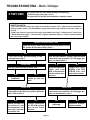
TROUBLESHOOTING:
4.
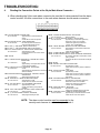
Reading the Connection Points at the 24 pin Main Alarm Connector :
A. When checking the 24 pin main alarm connector, be sure that it is disconnected from the alarm
control module. All other connections to the main alarm harness should remain connected.
1
2
3
4
5
6
7
8
9 10 11 12
13 14 15 16 17 18 19 20 21 22 23 24
24 PIN MAIN ALARM CONNECTOR
( TERMINAL VIEW )
PIN 1 - DOOR TRIGGER - BROWN WIRE
Pin 1 to Ground Approximately 12 Volts with all doors
closed.
0 Volts with LF or RF door opened.
PIN 2 - HOOD PIN SWITCH - DARK GREEN WIRE
Pin 2 to Ground No continuity with hood lid closed.
Continuity with hood lid opened.
PIN 3 - L.E.D. (+) - RED WIRE (Refer to NOTE below)
PIN 4 - L.E.D. (-) - LIGHT BLUE WIRE (Refer to NOTE below)
PIN 5 - ALL DOOR UNLOCK #1 - PINK w/ WHITE STRIPE WIRE
Pin 5 to Ground Approximately 12 Volts.
0 Volt pulse when LF door unlock switch
is activated.
PIN 6 - BLANK
PIN 7 - LF DOOR UNLOCK FROM RELAY - DARK BLUE w/ WHITE
STRIPE WIRE
Pin 7 to Ground 0 Volts.
Approximately 12 Volt pulse when LF door
unlock switch is activated.
PIN 8 - LF DOOR UNLOCK TO SOLENOID - WHITE WIRE
Pin 8 to Ground 0 Volts.
Approximately 12 Volt pulse when LF door lock
switch is activated.
PIN 9 - DRIVER'S DOOR UNLOCK SOURCE - ORANGE w/ WHITE
STRIPE WIRE
Pin 9 to Ground Always approximately 12 Volts.
PIN 10 - HORN RELAY - GREEN w/ RED STRIPE WIRE
Pin 10 to Ground Approximately 12 Volts.
0 Volts when horn switch is activated.
PIN 11 - TAILLIGHT RELAY - YELLOW/GREEN STRIPE WIRE
Pin 11 to Ground Approximately 12 Volts.
0 Volts when Parking Lamp switch is
activated.
PIN 12 - CTSY LIGHT SOURCE - BLACK w/ WHITE STRIPE WIRE
Pin 12 to Ground Always continuity.
PIN 13 - (+) 12 VOLT BATTERY SOURCE - RED WIRE
Pin 13 to Ground Always approximately 12 Volts.
PIN 14 - CHASSIS GROUND SOURCE - BLACK WIRE
Pin 14 to Ground Always continuity.
PIN 15 - (+) 12 VOLT IGNITION SOURCE - YELLOW WIRE
Pin 15 to Ground Approximately 12 Volts when ignition key
switched to " RUN " and " START ".
0 Volts when ignition key switched to
" LOCK " and " ACCESSORY ".
PIN 16 - TRUNK TRIGGER - BROWN w/ WHITE STRIPE WIRE
Pin 16 to Ground Approximately 12 Volts with trunk lid and all
doors closed.
0 Volts with trunk lid opened.
PIN 17 - ALARM CONTROL SWITCH - GREY WIRE
PIN 18 - ALARM CONTROL SWITCH - BLACK w/ ORANGE STRIPE WIRE
Pin 17 to Pin 18 No continuity with alarm control switch in OFF
(OUT ) position.
Continuity with alarm control switch in ON (IN)
position.
PIN 19 - BLANK
PIN 20 - DISARM - PINK w/BLACK STRIPE WIRE
Pin 20 to GroundApproximately 12 Volts.
0 Volts when LF door key switch is rotated to
unlock.
PIN 21 - DOOR LOCK WIRE - PINK WIRE
Pin 21 to Ground Approximately 12 Volts.
0 Volts when LF door lock switch is activated.
0 Volts when LF door key switch is rotated to
lock position.
PIN 22 - STARTER DISABLE RELAY - ORANGE WIRE
Pin 22 to Ground Approximately 12 Volts when ignition key
switched to " RUN " and " START ".
0 Volts when ignition key switched to
" LOCK " and " ACCESSORY ".
PIN 23 - HEADLIGHT RELAY - BLUE WIRE
Pin 23 to Ground Approximately 12 Volts.
0 Volts when Headlight switch is activated.
PIN 24 - COURTESY LIGHT - GREEN w/ WHITE STRIPE WIRE
Pin 24 to Ground Approximately 12 Volts with all doors closed
0 Volts with LF or RF door opened.
NOTE: The alarm control module must be connected to the
security main harness in order to test pins 3 and 4.
Page 12