1
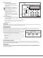
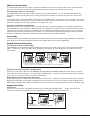
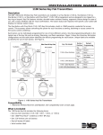
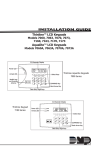
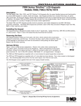
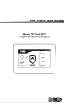
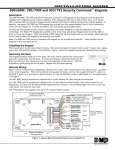
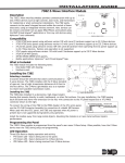
Installation Guide 9000 Series Wireless Keypads Description The DMP 9060 and 9063 are fully functioning supervised wireless keypads. They provide installation flexibility while also offering optional codeless arming and disarming capabilities. Each keypad provides: • Custom 32-character full LCD display • Three 2-button Panic keys • Backlit keyboard with easy-to-read lettering 32-Character Display • Internal speaker • Wall tamper protection • Keyboard backlighting turns Red in alarm conditions The Model 9063 keypad also provides a built-in proximity card reader designed to read DMP/HID proximity credentials for Select Keys codeless arming and disarming. Compatibility All DMP 1100 Series Wireless Receivers and Panels What is Included The 9000 Series Keypad includes the following items: • One wireless keypad mounted in a Thinline two-part housing (base and cover) • One internal rechargeable 3.7V lithium battery • One 12 VDC DC Plug-in Power Supply • Serial number label • Model 9063 also includes a built-in proximity card reader Backlit Logo and Proximity Antenna COMMAND Key Back Arrow Key Data Entry Digit keys Figure 1: 9000 Series Keypad Keypad Serial Number For your convenience, an additional pre-printed serial number label is included. Prior to installing the device, record the serial number or place the pre-printed serial number label on the panel programming sheet. This number is required during programming. Programming the Transmitter in the Panel The keypads can be programmed into the control panel by entering the serial number in Device Setup panel programming, or alternatively using the wireless keypad association operation (see below). A maximum of 4 keypads may be used with the panel. Device Setup Programming Program the keypad as a device in Device Setup during panel programming. At the serial number prompt, enter the eightdigit serial number. Continue to program the device as directed in the panel programming guide. Note: If the keypad serial number is entered manually, the Wireless Keypad Association operation is not required. Wireless Keypad Association Enable Wireless Keypad Association operation on both the keypad and panel. To enable association operation in the keypad, access the Installer Options Menu (3577 (INST)) and select RF Survey. The keypad logo LEDs turn on Red until association is successful. To enable association operation in the XTL panel, press the XTL RESET button 3 times within 12 seconds allowing 3 seconds between each press of the reset button. When in keypad association, the XTL Red and Green logo LEDs turn on steady. RCV J8 To enable association operation in the XR100/XR500, XR150/XR350/XR550 or XT30/XT50 panel, reset the panel 3 times within 12 seconds. Allow the keypad bus Transmit/Receive XMIT Programming LEDs to turn back on between each reset. For 60 seconds the panel listens for wireless keypads that are in the Installer Options Menu (3577 CMD) and have not been programmed, or associated into another panel. Those keypads are assigned to the first open device position automatically based upon the order in which they are detected. The keypad logo turns Green to indicate it has been associated with the panel. Selecting the Proper Location The 9000 Series keypads provide a built-in survey capability in the Installer Options menu to allow one person to confirm keypad communication with the panel. See Accessing Keypad Wireless Survey later in this document. Installing the Keypad Building Wall All DMP keypad housings are designed to easily install on any desk stand, 4” plastic square box, 3‑gang plastic switch box, or a flat surface. Do not install the keypad near any metal objects. 9000 Series Wireless Keypad Remove the Cover The keypad housing is made up of two parts: the cover, which contains the circuit board and keyboard components, and the base. Use the following steps and figures to separate the keypad cover and base. 1. Insert a flat screwdriver into one of the slots on the bottom of the keypad and gently lift the screwdriver handle toward you while pulling the halves apart. Repeat with the other slot. 2. Using your hands, gently separate the cover from the base and set aside. Lift screwdriver handle up toward you to separate keypad cover from base. Mounting the Keypad Secure the keypad to the wall ensuring that the wall tamper switch makes proper contact with the wall. Use the supplied screws in the mounting hole locations as shown in Figure 3. Primary DC Power Supply Black (-) Locate the keypad near a wall outlet to allow connection of the Model 371-500 plug-in DC power supply. In addition to powering the keypad, the power supply also charges the internal back-up battery. The plug-in power supply provides a six foot cord. The cord can be lengthened, but should be located within 100 feet of the keypad using 22 AWG wire. OBSERVE POLARITY WHEN EXTENDING THE POWER SUPPLY CORD. When the power supply connector is plugged into the keypad, the internal battery is automatically connected. The keypad can operate from battery only as long as the power supply connector is plugged into the keypad. Black/White stripe (+) Figure 2: DC Power Supply Connector Standby Battery The keypad rechargeable battery provides 24 hours of backup battery power when primary DC power is not available. It is shipped already installed inside the keypad. The battery is intended for backup power only and not to operate the keypad on a daily basis. If the battery is low, or not plugged into the internal J3 battery connector, a low battery condition is indicated by the panel when the battery falls below 3.62 volts. To restore the keypad from a low battery state, the voltage must be above 3.62. Use the following steps to replace the battery. DMP recommends replacing the battery every 3 years under normal use. Note: If removing the keypad from service, disconnect the power supply connector from the back of the keypad to avoid discharging the battery. Removing the Keypad PCB 1. Disconnect the power supply connector from the back of the keypad. 2. Remove from the base. 3. Loosen the top keypad PCB snaps. 4. Lean the keypad PCB backwards and lift out from the bottom PCB snaps. Top PCB Snaps Surface and Backbox Mounting Holes Keypad Back Black (-) Combined 4-square and 3-gang switch box Mounting Holes Black/White stripe (+) Surface and Backbox Mounting Holes Figure 3: Mounting Holes Digital Monitoring Products 2 4 Position header Wall Tamper PCB Alignment post Bottom PCB Snaps Figure 4: PCB Snaps 9000 Series Installation Guide Battery Replacement Standby battery connector 1. Disconnect the battery lead connector from the keypad J3 battery header. 2. Squeeze the battery straps to remove the standby battery. 3. Properly dispose of the used battery. Caution: Risk of fire, explosion, and burns. Do not disassemble, heat above 212°F (100°C), or incinerate. Red Black 4. Place the new battery (DMP Model 9000BAT) on the keypad PCB and replace the battery straps. 5. Observe polarity and connect the battery lead connector to the keypad J3 battery header. Standby battery straps Installing Keypad PCB 1. Set the keypad PCB into the bottom snaps with the elastomer keyboard already in place. See Figure 4. Figure 5: Battery Replacement 2. Line up the PCB alignment post with the hole in the keypad PCB. 3. Press the PCB into the top PCB snaps to secure in place. 4. Replace the base. Card Reader When a proximity credential is presented to the Model 9063 internal reader, located behind the backlit logo, a beep tone is emitted to provide an audible acknowledgement of the credential read. Panic Key Options 2-Button Panic Keys All keypads offer Panic key function that allows users to send Panic, Emergency, or Fire reports to the central station. Enable the Panic key function in the keypad user menu. See Programming Keypad Options later in this document. Install the supplied icon labels below the top row of Select keys. The user must press and hold the two Select keys for two seconds until a beep from the keypad is heard. At the beep, the panel sends the following zone alarm reports to the central station: Panic (left two Select keys)—Zone 19 with Device Name Note: If using the panic key, do not use Zone 19 in the XTL panel programming. Top Row Select Keys Panic Emergency Fire Emergency—non-medical (center two Select keys)—Zone 29 with Device Name Fire (right two Select keys)—Zone 39 with Device Name Internal Speaker Operation All keypads emit standard tones for key presses, entry delay, and system alerts. The speaker also provides distinct burglary, fire, zone monitor, and prewarn cadences. The keypads provide an alternate prewarn with alarm cadence that occurs when the status list displays a zone alarm. Backlighting The keyboard lights when a key is pressed or the speaker sounds. During an alarm condition, the keyboard lighted area turns Red. When all alarm conditions are cleared from the display, the Red display turns off and the lighted area returns to the user-selected brightness. 9000 Series Installation Guide Digital Monitoring Products 3 Backlit Logo The backlit logo indicates the armed status of the panel and the power and battery status of the keypad. Depending on the status, the LED displays in Red or Green as listed in the table. Color and Activity Green Steady Green Blinking No Light Red Steady Red/Green Alternate Red Blinking Armed Status Panel Disarmed Panel Disarmed Panel Disarmed Panel Armed Panel Armed Panel Armed Keypad Power Status Primary Power OK, Battery OK Primary Power OK, Battery Fault Primary Power Fault, Battery OK Primary Power OK, Battery OK Primary Power OK, Battery Fault Primary Power Fault, Battery OK End-User Options All keypads provide three keypad adjustments the end-user can make through a User Options Menu. The user can also view the keypad model number and serial number. On all keypads press and hold the Back Arrow (<—) and CMD (COMMAND) keys for two seconds to access User Options. The keypad display changes to SET BRIGHTNESS. Use the COMMAND key to display the next Option or press the Back Arrow to exit. Backlighting Brightness Set brightness < > Set the keypad LCD Display brightness level, and the Green keyboard backlighting. Use the left Select key to lower the brightness and the right Select key to raise the brightness. If the brightness level is lowered, it reverts to maximum intensity whenever a key is pressed. If no keys are pressed, and the speaker has not sounded for 10 seconds, the user-selected brightness level restores. Note: During primary power loss, the backlighting turns completely off after the 10 seconds of no activity to conserve the standby battery. < Internal Speaker Tone Set TONE > Set the keypad internal speaker tone. At the SET TONE display, use the left Select key to lower the tone and the right Select key to raise the tone. Internal Volume Level Set VOLUME LEVEL < > Set the keypad internal speaker volume for key presses and entry delay tone conditions. During alarm and trouble conditions, the volume is always at maximum level. Use the left Select key to decrease the volume and the right Select key to increase the volume. Model number 9060 v100 081310 Model Number The LCD displays the keypad model number and firmware version/date. SERIAL#: Serial Number Display The LCD displays the keypad serial number. A Entering Alpha Characters C ( First Letter Third Letter Second Letter Special Character 9 YZ PQ 0 R * -. 8 ST I U L JK ? 4 GH X , 6 F ! 7 DE $ ) O 3 & MN 2 # AB 5 C ( 1 / Each key also has a special, non-alpha character. These characters are not shown on the keypad. Enter a space by pressing 9 then the third Select key. The following nonalpha characters are available: ( ) ! ? / & $ ‚ (space) ’ starting with the left bracket on the 1 digit key to the blank space and apostrophe on the 9 digit key. Use the 0 digit key to enter - . * # (dash, period, asterisk, or number sign). ' Entering Non-Alphanumeric Characters Entering Alpha Characters (s pa ce ) To enter an alpha character, press the key that has the desired letter written below it. The keypad display shows the number on that key. To change the number to a letter, press the top row Select key that corresponds to the letter location under the key. For example, if you press key number 1, the letters for that key are A, B, and C. Press the first Select key for A, the second Select key for B, the third Select key for C, and the fourth Select key for special characters. B VW CMD Keys with Non-Alpha Characters Digital Monitoring Products 4 9000 Series Installation Guide Installer Options Menu All keypads provide Keypad Option and Keypad Diagnostic menus to allow installing and service technicians to configure and test keypad operation. Accessing Installer Options Access the Installer Options Menu through the User Options function. Hold down the Back Arrow and COMMAND keys for two seconds to display SET BRIGHTNESS. Enter the code 3577 (INST) and press COMMAND. The display changes to KPD OPT (keypad options), KPD DIAG (keypad diagnostics), KPD RF (wireless survey), and STOP. The Keypad Options menu allows you to set the default keypad message, enable 2-button Panic keys, and several additional keypad options. Additionally, the keypad must be operating anywhere in the Installer Options menu, 3577 (INST), to be automatically associated by the control panel receiver. To place the keypad into the association operation, first remove the power connector from the back of the keypad. Then reapply power and access the Installer Options menu. See Keypad Wireless Survey for more information. Programming Keypad Options KPD KPD KPD OPT DIAG RF STOP Keypad Options (KPD OPT) To program keypad options, press the left Select key under KPD OPT. DEFAULT KEYPAD MSG: Default Keypad Message Enter a custom message of up to 16 characters to appear on the keypad display top line whenever that line is not used for any other purpose. Press any Select key to clear the current message and enter a new custom display. Arm Panic Keys Use this option to configure the top row Select keys as 2-button Panic keys. To enable or disable a Panic, press the Select key under the appropriate display: PN (Panic), EM (Emergency), and FI (Fire). Once the panic is enabled, an asterisk displays next to the description. Refer to the Panic Key Options section earlier in this document. Number of User Code Digits Set the Number of User Code Digits to match panel operation. The XTL Series panel recognizes four digit user codes. The XR100/XR500 with Version 211 software and XR150/XR350/XR550 panels recognize ten digits (9063 only). Arm panic keys: *PN*em *FI No of user code digits: All?:Noyes Arming/Disarming Wait Time (9063 only) Delay: 2 Select the number of seconds (1-9) the keypad should wait after a credential is presented and an area system displays ALL? NO YES during arming/disarming or a HOME/SLEEP/AWAY system waits during arming only. If NO or YES, or HOME, SLEEP, or AWAY is not manually selected before the delay expires, the keypad automatically selects the YES or the AWAY key. Select zero (0) to disable this feature. Default is 2. Enable Tamper? enable Tamper? NO yes Select YES to enable wall tamper protection. Default is NO. The following options are for programming the internal proximity reader of the Model 9063 only. Card Options CARD OPTIONS Select DMP to indicate the reader sends a 26-bit DMP data string. To save the DMP option, press DMP CUSTOM the left top row Select key under DMP. Default is DMP. Select CUSTOM if using a non-DMP credential. To select CUSTOM press the right top row Select key. Custom Card Definitions WIEGAND CODE LENGTH: 26 Wiegand Code Length When using a custom credential, enter the total number of bits to be received in Wiegand code including parity bits. Press any top row Select key to enter a number between 0-255 to equal the number of bits. Default is 26 bits. Typically, an access card contains data bits for a site code, a user code, and start/stop/parity bits. The starting position location and code length must be determined and programmed into the keypad. 01110101101101010001100111 First Bit Received Position = 0 Site Code Position = 1 Length = 8 User Code Position = 9 Length = 16 Last Bit Received Position = 25 In this example the HID Wiegand Code Length = 26 bits. 9000 Series Installation Guide Digital Monitoring Products 5 Site Code Position Enter the site code start position in the data string. Press any Select key to enter a number between 0-255. Default is 1. SITE CODE Position: 1 SITE CODE Length: 8 Site Code Length Enter the number of characters the site code contains. Press any Select key to enter a number between 1-16. Default is 8. User Code Position User CODE Position: 9 Define the User Code start bit position. Press any Select key to enter a number between 0-255. Default is 9. User CODE Length: 16 User Code Length Define the number of User Code bits. Press the fourth Select key to enter a custom number. Custom numbers can only be a number between 16‑32. Press COMMAND to save the entry. The default is the DMP value of 16. Require Site Code Require site Code: noyes Press the top row Select key under YES to use a site code and press COMMAND to view the site code entry display. Default is NO. Note: A card with a site code greater than three digits cannot be used. Use only cards with three-digit site codes. Site codes 1-4 > > > > Site Codes 1-4 Enter site codes 1-4 (left to right separated by > sign). Press the Select key below the > sign to add, delete, or change the site code and press COMMAND. Site code range is 0-999. Press the COMMAND key to display SITE CODES 5-8. SITE CODES 5-8 > > > > Site Codes 5-8 Enter site codes 5-8 (left to right separated by > sign). Press the Select key below the > sign to add, delete, or change the site code and press COMMAND. Site code range is 0-999. Degraded mode Degraded Mode Note: The Degraded Mode option appears in programming, but does not currently apply to the 9000 Series Keypad. Accessing Keypad Diagnostics If necessary, refer to Accessing Installer Options earlier in this document. Keypad Diagnostics (KPD DIAG) KPD KPD KPD The Keypad Diagnostic option allows you to check the display segments, keyboard backlighting OPT DIAG RF STOP and test individual keys. Press the Select key under KPD DIAG. The keypad lights all display segments and illuminates the keyboard in Red. In approximately one second the keyboard backlighting changes to Green. The keypad alternates between these two states for approximately two minutes. Press COMMAND at any time to begin testing individual keys. Press key to Test Test Individual Keys The display changes to PRESS KEY TO TEST. This option tests each key on the keyboard to ensure it is operating properly. Press and hold each key for about two seconds. The key number being held appears in the display. Verify the correct number displays before testing the next key. Input wiegand Input Wiegand (9063 only) This option tests the internal input from proximity credentials. The display shows OKAY each time a good proximity read is received. Accessing Keypad Wireless Survey Access the Installer Options Menu through the User Options function. Hold down the Back Arrow and COMMAND keys for two seconds to display SET BRIGHTNESS. Enter the code 3577 (INST) and press COMMAND. KPD KPD KPD OPT DIAG RF STOP rf survey Keypad Wireless Survey (KPD RF) Press the Select key under KPD RF to start the RF communication survey test. The keypad logo turns on Red indicating communication has not been established with the panel receiver. When successful communication has been established, the keypad logo turns Green. ote: The keypad RF survey is a good option to use during the keypad association programming N by the control panel. The backlit logo turns Green to indicate that it has been associated by the panel. Exiting the Installer Options When done, press the COMMAND key once to return to the Installer Options screen. Press the Select key under STOP to exit the Installer Options function. Digital Monitoring Products 6 9000 Series Installation Guide Additional Programming The 9063 keypads allow users to present a proximity credential to the built-in proximity reader. Users can also manually enter their user code into the keypad. The keypad verifies the user code and its authority with the panel. Programming Cards into the System This programming feature operates on 9063 keypads only. Access the User Menu in one of two ways. When MENU? NO YES displays, choose YES and present your proximity credential to the reader or manually enter your user code into the keypad. From the User Menu, select USER CODES?. Choose ADD. At the ENTER CODE: - display, present the credential to the reader. The keypad works by reading the user code from the data sent by the proximity reader. For more information, refer to the panel User’s Guide section on adding, deleting, and changing user codes. Proximity Credentials Compatibility DMP Keypads with internal proximity readers are compatible with most standard 125Khz Prox credentials available from HID and all DMP proximity credentials. DMP Keypads are not compatible with iClass or other non-HID credentials. There are custom and non-standard credentials from HID that are not compatible with DMP proximity keypads. If you are using HID cards that have not been purchased directly from DMP, it is recommended to thoroughly test the application fully before installation. DMP does not guarantee compatibility with credentials not purchased from DMP. User’s Guide This User’s Guide covers all 9000 Series keypads and contains different sections: Keypad Arming and Disarming, and Keypad Entry Delay. All of the examples displayed assume that CLOSING CODE is YES in panel programming. Keypad Arming and Disarming Area System Arming and Disarming Press COMMAND, the keypad displays ARM DISARM. Press the Select key under either option. The keypad displays ENTER CODE: -. Present your card to the reader. Once validated by the system, all areas assigned to your code arm or disarm automatically. ABC SECURITY ARM DISARM ABC SECURITY ENTER CODE: – ABC SECURITY ALL? NO YES Select NO to arm or disarm individual areas. Select YES, or simply wait, to automatically arm or disarm all areas for which you are authorized. Figure 6: Area Arming and Disarming All/Perimeter System Arming and Disarming Present your card to the reader or press COMMAND, the keypad displays DISARM? or PERIM ALL (when arming). Press the Select key under the desired option. The keypad displays ENTER CODE: -. Present your card to the reader. Once validated by the system, the selected areas arm or disarm automatically. Home/Away System Arming and Disarming Present your card to the reader. If the system is armed, once the card is validated, all areas are disarmed and the keypad displays ALL SYSTEM OFF. If the system is disarmed when you present your card, once the card is validated, HOME SLEEP AWAY displays. Manually select HOME, SLEEP, AWAY or after a short time-out, all areas automatically arm in the AWAY mode. Keypad Entry Delay All Systems Once the entry delay starts, the keypad sounds an entry tone and displays ENTER CODE: - . Present your card to the reader. Once validated by the system, all areas assigned to your code arm or disarm automatically. ABC SECURITY ENTER CODE: – Entry delay starts. The System disarms the areas to which you are authorized. Figure 7: Entry Delay 9000 Series Installation Guide Digital Monitoring Products 7 FCC Information This device complies with Part 15 of the FCC Rules. Operation is subject to the following two conditions: (1) This device may not cause harmful interference, and (2) this device must accept any interference received, including interference that may cause undesired operation. Changes or modifications made by the user and not expressly approved by the party responsible for compliance could void the user’s authority to operate the equipment. Note: This equipment has been tested and found to comply with the limits for a Class B digital device, pursuant to part 15 of the FCC Rules. These limits are designed to provide reasonable protection against harmful interference in a residential installation. This equipment generates, uses and can radiate radio frequency energy and, if not installed and used in accordance with the instructions, may cause harmful interference to radio communications. However, there is no guarantee that interference will not occur in a particular installation. If this equipment does cause harmful interference to radio or television reception, which can be determined by turning the equipment off and on, the user is encouraged to try to correct the interference by one or more of the following measures: - Reorient or relocate the receiving antenna. - Increase the separation between the equipment and receiver. - Connect the equipment into an outlet on a circuit different from that to which the receiver is connected. - Consult the dealer or an experienced radio/TV technician for help. Compliance Listing Specifications Commercial Burglary Set the Enable Tamper option to YES for all listed commercial burglary applications. Use DMP proximity cards only for listed applications. 12 VDC, 500mA Standby Battery 9000BAT Voltage 3.7 VDC Capacity 800Ah Type Lithium Polymer Rechargeable Standby Time 24 Hours Frequency Range: 903-927 MHz Dimensions: 7” W x 5.25” H x 0.5” D Color: White Housing Material Flame retardant ABS Compatibility 1100D Wireless Receiver 1100DH Wireless High Power Receiver 1100DI Wireless In-line Receiver 1100X Wireless Receiver 1100XH Wireless High Power Receiver XTL/XTLN/XTLN-WiFi Panels with integrated wireless receiver XT30/XT50 Series Panels using version 106 software XR100/XR500 Series Panels using version 207 software XR150/XR350/XR550 Series Panels Accessories 371-500 12 VDC Plug-in Power Supply 9000BAT Replacement Standby Battery 699 Keypad Deskstand 777 Protective Keypad Cover Proximity Credentials 1306P Prox Patch™ 1306PW Prox Patch™ 26-Bit 1326 HID ProxCard II® Card 1386 HID ISOProx II® Card 1346 HID ProxKey II® Access Device Certifications ANSI/SIA CP-01-2010 False Alarm Reduction FCC Part 15 RFID Reader FCC ID: CCKPC0126 Industry Canada: 5251A-PC0126 ANSI/UL 1023 Household Burglar Alarm System Units ANSI/UL 1610 Central Station Burglar Alarm Units ANSI/UL 985 Household Fire Warning System Patents U. S. Patent No. 7,239,236 800-641-4282 INTRUSION • FIRE • ACCESS • NETWORKS www.dmp.com 2500 North Partnership Boulevard Designed, Engineered and Assembled in U.S.A. Springfield, Missouri 65803-8877 15055 Operating Voltage LT-1107 1.04 © 2015 Digital Monitoring Products, Inc. Specifications